Enhanced PID for Air Compressors F7 Drive Software ...
17
Enhanced PID for Air Compressors F7 Drive Software Technical Manual Software Number: VSF11020X, Drive Models: CIMR-F7UXXXXXX-096 Document Number: TM.F7SW.096, Date: 08/01/05, Rev: 05-08
Transcript of Enhanced PID for Air Compressors F7 Drive Software ...

Enhanced PID for Air Compressors
F7 Drive Software Technical Manual
Software Number: VSF11020X, Drive Models: CIMR-F7UXXXXXX-096 Document Number: TM.F7SW.096, Date: 08/01/05, Rev: 05-08

Date: 08/01/05, Rev: 05-08 Page 2 of 17 TM.F7SW.096
This document is intended to provide proper installation and use of the Yaskawa drive with custom software. This document is a supplement to the standard drive technical manual. It describes the effects on the drive parameters and functions with the software installed. Read and understand this document and the standard drive technical manuals before attempting to install, adjust, operate, inspect or maintain the drive. Observe all cautions and warnings in this document and the standard drive technical manuals. Custom software is written to add functionality to a standard AC drive to enhance or enable use in a specific application. The software is loaded to the flash ROM area of the control board, and replaces the standard drive software. Custom software can add new functions, modify standard functions, or even inhibit standard functions. It can be used to modify display text or parameter names. Custom software is usually loaded to the drive before delivery. The control board and drive nameplate are assigned unique part numbers and the software is registered, archived, and retrievable. When seeking support for a drive with custom software, it is imperative to provide the unique part number shown on the drive nameplate. The software has been flashed to the control board memory and the operation of parameters, functions, and monitors are different than the standard drive software, as described herein. 1.0 Overview
The drive’s standard PID algorithm and display has been modified to provide optimum control of non-reciprocating rotary screw air compressors. The PID features are designed to expand the functionality and correct some deficiencies of the drive’s standard PID algorithm. The enhanced PID function utilizes the parameters of the standard software PID function (B5 group) as well as many new P group parameters.

Date: 08/01/05, Rev: 05-08 Page 3 of 17 TM.F7SW.096
1.1 Simplified Block Diagram of Enhanced PID: 2 Input (B5-01 = 1 or 2)
1.2 Simplified Block Diagram of Enhanced PID: 3 Input (B5-01 = 3 or 4) (PID setpoint is independent of frequency reference)
1.3 Simplified Block Diagram of Enhanced PID: 2 Input (B5-01 = 3 or 4) (PID setpoint is same as the frequency reference)
Date: 08/01/05, Rev: 05-08 Page 4 of 17 TM.F7SW.096
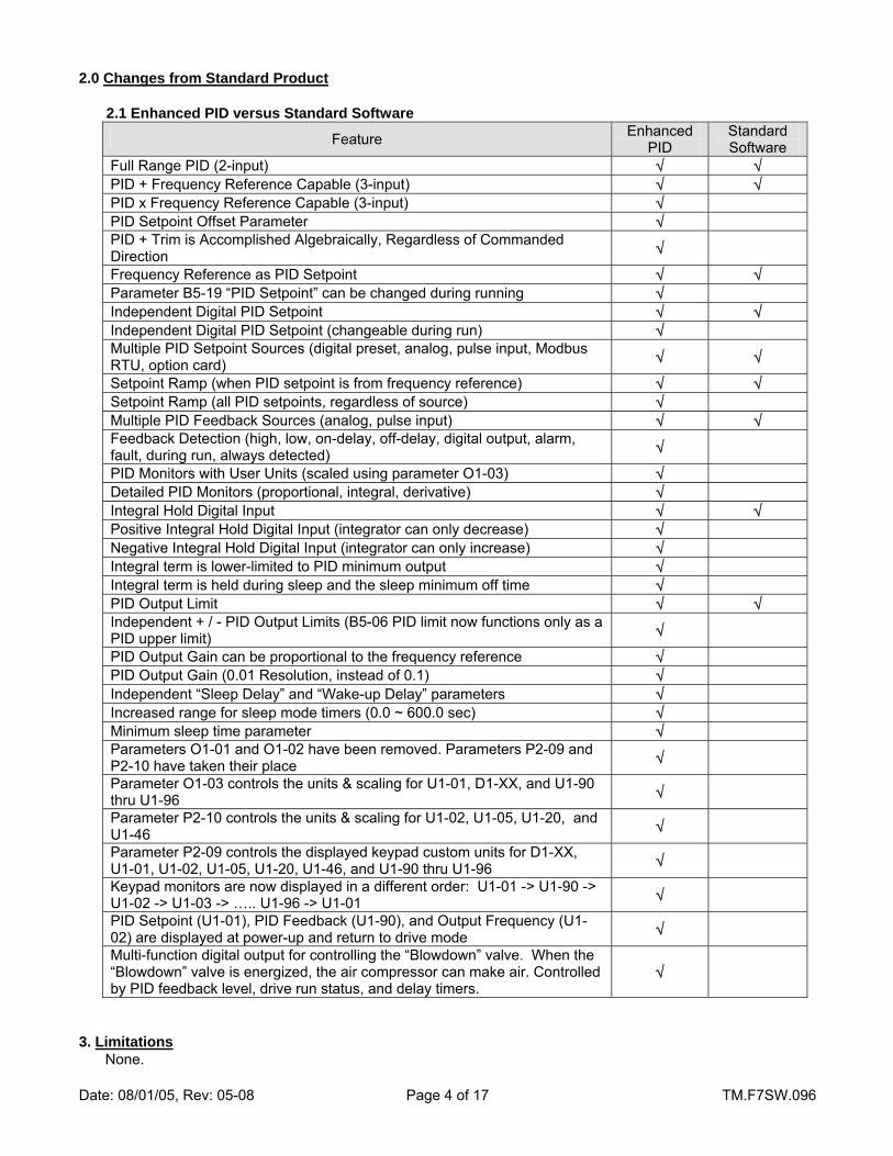
2.0 Changes from Standard Product
2.1 Enhanced PID versus Standard Software
Feature Enhanced PID
Standard Software
Full Range PID (2-input) √ √ PID + Frequency Reference Capable (3-input) √ √ PID x Frequency Reference Capable (3-input) √ PID Setpoint Offset Parameter √ PID + Trim is Accomplished Algebraically, Regardless of Commanded Direction √
Frequency Reference as PID Setpoint √ √ Parameter B5-19 “PID Setpoint” can be changed during running √ Independent Digital PID Setpoint √ √ Independent Digital PID Setpoint (changeable during run) √ Multiple PID Setpoint Sources (digital preset, analog, pulse input, Modbus RTU, option card) √ √
Setpoint Ramp (when PID setpoint is from frequency reference) √ √ Setpoint Ramp (all PID setpoints, regardless of source) √ Multiple PID Feedback Sources (analog, pulse input) √ √ Feedback Detection (high, low, on-delay, off-delay, digital output, alarm, fault, during run, always detected) √
PID Monitors with User Units (scaled using parameter O1-03) √ Detailed PID Monitors (proportional, integral, derivative) √ Integral Hold Digital Input √ √ Positive Integral Hold Digital Input (integrator can only decrease) √ Negative Integral Hold Digital Input (integrator can only increase) √ Integral term is lower-limited to PID minimum output √ Integral term is held during sleep and the sleep minimum off time √ PID Output Limit √ √ Independent + / - PID Output Limits (B5-06 PID limit now functions only as a PID upper limit) √
PID Output Gain can be proportional to the frequency reference √ PID Output Gain (0.01 Resolution, instead of 0.1) √ Independent “Sleep Delay” and “Wake-up Delay” parameters √ Increased range for sleep mode timers (0.0 ~ 600.0 sec) √ Minimum sleep time parameter √ Parameters O1-01 and O1-02 have been removed. Parameters P2-09 and P2-10 have taken their place √
Parameter O1-03 controls the units & scaling for U1-01, D1-XX, and U1-90 thru U1-96 √
Parameter P2-10 controls the units & scaling for U1-02, U1-05, U1-20, and U1-46 √
Parameter P2-09 controls the displayed keypad custom units for D1-XX, U1-01, U1-02, U1-05, U1-20, U1-46, and U1-90 thru U1-96 √
Keypad monitors are now displayed in a different order: U1-01 -> U1-90 -> U1-02 -> U1-03 -> ….. U1-96 -> U1-01 √
PID Setpoint (U1-01), PID Feedback (U1-90), and Output Frequency (U1-02) are displayed at power-up and return to drive mode √
Multi-function digital output for controlling the “Blowdown” valve. When the “Blowdown” valve is energized, the air compressor can make air. Controlled by PID feedback level, drive run status, and delay timers.
√
3. Limitations
None.
Date: 08/01/05, Rev: 05-08 Page 5 of 17 TM.F7SW.096
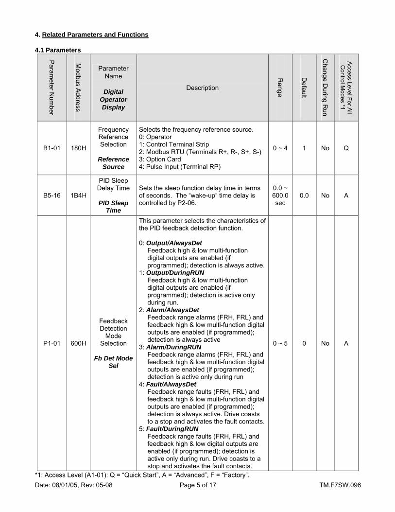
4. Related Parameters and Functions 4.1 Parameters
Param
eter Num
ber
Modbus A
ddress
Parameter Name
Digital
Operator Display
Description
Range
Default
Change D
uring Run
Access Level For A
ll C
ontrol Modes *1
B1-01 180H
Frequency Reference Selection
Reference
Source
Selects the frequency reference source. 0: Operator 1: Control Terminal Strip 2: Modbus RTU (Terminals R+, R-, S+, S-) 3: Option Card 4: Pulse Input (Terminal RP)
0 ~ 4 1 No Q
B5-16 1B4H
PID Sleep Delay Time
PID Sleep
Time
Sets the sleep function delay time in terms of seconds. The “wake-up” time delay is controlled by P2-06.
0.0 ~ 600.0 sec
0.0 No A
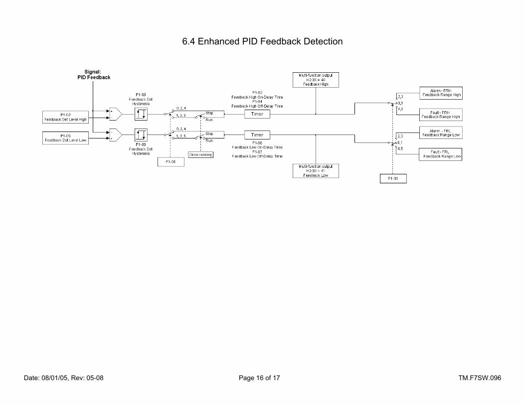
P1-01 600H
Feedback Detection
Mode Selection
Fb Det Mode
Sel
This parameter selects the characteristics of the PID feedback detection function. 0: Output/AlwaysDet
Feedback high & low multi-function digital outputs are enabled (if programmed); detection is always active.
1: Output/DuringRUN Feedback high & low multi-function digital outputs are enabled (if programmed); detection is active only during run.
2: Alarm/AlwaysDet Feedback range alarms (FRH, FRL) and feedback high & low multi-function digital outputs are enabled (if programmed); detection is always active
3: Alarm/DuringRUN Feedback range alarms (FRH, FRL) and feedback high & low multi-function digital outputs are enabled (if programmed); detection is active only during run
4: Fault/AlwaysDet Feedback range faults (FRH, FRL) and feedback high & low multi-function digital outputs are enabled (if programmed); detection is always active. Drive coasts to a stop and activates the fault contacts.
5: Fault/DuringRUN Feedback range faults (FRH, FRL) and feedback high & low digital outputs are enabled (if programmed); detection is active only during run. Drive coasts to a stop and activates the fault contacts.
0 ~ 5 0 No A
*1: Access Level (A1-01): Q = “Quick Start”, A = “Advanced”, F = “Factory”.
Date: 08/01/05, Rev: 05-08 Page 6 of 17 TM.F7SW.096
4.1 Parameters (continued)
Param
eter N
umber
Modbus A
ddress
Parameter Name
Digital Operator Display
Description
Range
Default
Change D
uring R
un
Access Level For A
ll C
ontrol Modes *1
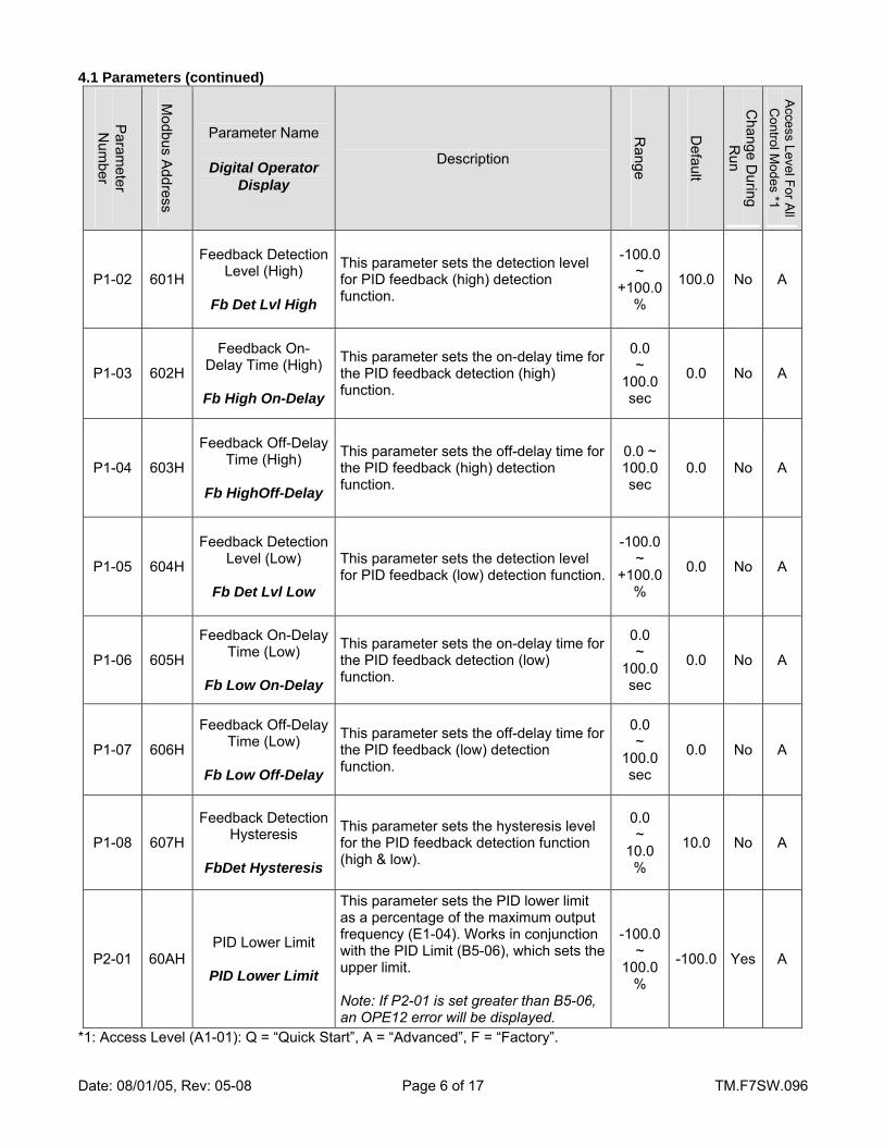
P1-02 601H
Feedback Detection Level (High)
Fb Det Lvl High
This parameter sets the detection level for PID feedback (high) detection function.
-100.0 ~
+100.0 %
100.0 No A
P1-03 602H
Feedback On- Delay Time (High)
Fb High On-Delay
This parameter sets the on-delay time for the PID feedback detection (high) function.
0.0 ~
100.0 sec
0.0 No A
P1-04 603H
Feedback Off-Delay Time (High)
Fb HighOff-Delay
This parameter sets the off-delay time for the PID feedback (high) detection function.
0.0 ~ 100.0 sec
0.0 No A
P1-05 604H
Feedback Detection Level (Low)
Fb Det Lvl Low
This parameter sets the detection level for PID feedback (low) detection function.
-100.0 ~
+100.0 %
0.0 No A
P1-06 605H
Feedback On-Delay Time (Low)
Fb Low On-Delay
This parameter sets the on-delay time for the PID feedback detection (low) function.
0.0 ~
100.0 sec
0.0 No A
P1-07 606H
Feedback Off-Delay Time (Low)
Fb Low Off-Delay
This parameter sets the off-delay time for the PID feedback (low) detection function.
0.0 ~
100.0 sec
0.0 No A
P1-08 607H
Feedback Detection Hysteresis
FbDet Hysteresis
This parameter sets the hysteresis level for the PID feedback detection function (high & low).
0.0 ~
10.0 %
10.0 No A
P2-01 60AH PID Lower Limit
PID Lower Limit
This parameter sets the PID lower limit as a percentage of the maximum output frequency (E1-04). Works in conjunction with the PID Limit (B5-06), which sets the upper limit. Note: If P2-01 is set greater than B5-06, an OPE12 error will be displayed.
-100.0 ~
100.0 %
-100.0 Yes A
*1: Access Level (A1-01): Q = “Quick Start”, A = “Advanced”, F = “Factory”.

Date: 08/01/05, Rev: 05-08 Page 7 of 17 TM.F7SW.096
4.1 Parameters (continued)
Param
eter N
umber
Modbus A
ddress
Parameter Name
Digital Operator Display
Description
Range
Default
Change D
uring R
un
Access Level For A
ll C
ontrol Modes *1
P2-02 60BH PID Output Gain 2
Output Gain 2
This parameter sets the gain at the output of the PID. Functions the same as PID Output Gain (B5-10), but with finer resolution (0.01 versus 0.1). The total output gain is determined by B5-10 x P2-02.
0.00 ~
25.00 1.00 No A
P2-03 60CH PID Setpoint Offset
Setpoint Offset
This parameter sums with the PID setpoint (analog input, pulse input, network communication, or parameter) to provide an offset.
-100.0 ~
+100.0 %
0.0 No A
P2-04 60DH
PID Trim Mode Selection
PID Trm Mode Sel
This parameter selects how the PID output will trim the frequency reference. Active only when b5-01 = 3 or 4. 0: Constant
The PID output trim is independent of the frequency reference.
1: Freq Ref Prop The PID output trim is proportional to the frequency reference.
0 ~ 1 0 No A
P2-05 60EH
Frequency Reference
Proportional Trim Lower Limit
FrefProp Low Lim
This parameter sets the lower limit of the PID output trim of the frequency reference when P2-01 = 1 (trim is proportional to the frequency reference). Active only when b5-01 = 3 or 4 and P2-04 = 1.
0.00 ~
100.00 %
10.00 Yes A
P2-06 60FH
Wake-Up Delay Timer
Wake Up Delay
This parameter determines the time delay after the frequency reference exceeds the sleep level, that the drive will resume running.
0.0 ~
600.0 sec
1.0 No A
P2-07 610H
Minimum Off-Time during sleep
operation
Min Off Time
This parameter determines the minimum amount of time the drive will be off during sleep mode to allow the pressure in the sump to dissipate.
0.0 ~
6000.0 sec
30.0 No A
P2-08 611H
Blowdown Valve Delay Time
Blowdown Delay
This parameter determines (after the drive is started or re-started after a sleep cycle) how long the drive has to run for before closing the multi-function digital output “blowdown valve”.
0.0 ~
120.0 sec
3.0 No A
*1: Access Level (A1-01): Q = “Quick Start”, A = “Advanced”, F = “Factory”.

Date: 08/01/05, Rev: 05-08 Page 8 of 17 TM.F7SW.096
4.1 Parameters (continued)
Param
eter N
umber
Modbus A
ddress
Parameter Name
Digital Operator Display
Description
Range
Default
Change D
uring R
un
Access Level For A
ll C
ontrol Modes *1
P2-09 612H
Custom Units Display Selection
Custom Units
This parameter determines what custom units are displayed for U1-01, D1-XX, and U1-90 thru U1-96. 0: No units displayed 1: PSI 2: kPa 3: oF Note: Only applicable when O1-03 ≥ 40 (custom units).
0 ~ 3 1 No A
P2-10 612H
Output Monitor Units
Output Mon Units
Selects the units & scaling for the following keypad monitors: U1-02, U1-05, U1-20, and U1-46. Works in the same fashion as parameter O1-03. 0: Hz 1: % 2 ~ 38: RPM (Set motor poles) 40 ~ 39999: Custom
0 ~ 39999 0 No A
*1: Access Level (A1-01): Q = “Quick Start”, A = “Advanced”, F = “Factory”.
Date: 08/01/05, Rev: 05-08 Page 9 of 17 TM.F7SW.096
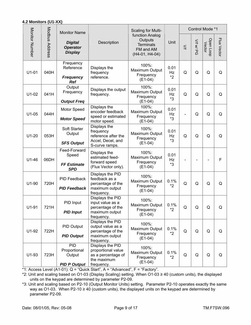
4.2 Monitors (U1-XX)
Control Mode *1
Monitor N
umber
Modbus A
ddress
Monitor Name
Digital Operator Display
Description
Scaling for Multi-function Analog
Outputs Terminals
FM and AM (H4-01, H4-04)
Unit V/f
V/f w
/ PG
Open Loop V
ector
Flux Vector
U1-01 040H
Frequency Reference
Frequency
Ref
Displays the frequency reference.
100%: Maximum Output
Frequency (E1-04)
0.01 Hz *2
Q Q Q Q
U1-02 041H
Output Frequency
Output Freq
Displays the output frequency.
100%: Maximum Output
Frequency (E1-04)
0.01 Hz *3
Q Q Q Q
U1-05 044H Motor Speed
Motor Speed
Displays the encoder feedback speed or estimated motor speed.
100%: Maximum Output
Frequency (E1-04)
0.01 Hz *3
- Q Q Q
U1-20 053H
Soft Starter Output
SFS Output
Displays the frequency reference after the Accel, Decel, and S-curve ramps.
100%: Maximum Output
Frequency (E1-04)
0.01 Hz *3
Q Q Q Q
U1-46 06DH
Feed-Forward Speed
FF Estimate
SPD
Displays the estimated feed-forward speed (Flux Vector only).
100%: Maximum Output
Frequency (E1-04)
0.01 Hz *3
- - - F
U1-90 720H PID Feedback
PID Feedback
Displays the PID feedback as a percentage of the maximum output frequency.
100%: Maximum Output
Frequency (E1-04)
0.1% *2 Q Q Q Q
U1-91 721H PID Input
PID Input
Displays the PID input value as a percentage of the maximum output frequency.
100%: Maximum Output
Frequency (E1-04)
0.1% *2 Q Q Q Q
U1-92 722H PID Output
PID Output
Displays the PID output value as a percentage of the maximum output frequency.
100%: Maximum Output
Frequency (E1-04)
0.1% *2 Q Q Q Q
U1-93 723H
PID Proportional
Output
PID P Output
Displays the PID proportional value as a percentage of the maximum frequency.
100%: Maximum Output
Frequency (E1-04)
0.1% *2 Q Q Q Q
*1: Access Level (A1-01): Q = “Quick Start”, A = “Advanced”, F = “Factory”. *2: Unit and scaling based on O1-03 (Display Scaling) setting. When O1-03 ≥ 40 (custom units), the displayed
units on the keypad are determined by parameter P2-09. *3: Unit and scaling based on P2-10 (Output Monitor Units) setting. Parameter P2-10 operates exactly the same
way as O1-03. When P2-10 ≥ 40 (custom units), the displayed units on the keypad are determined by parameter P2-09.
Date: 08/01/05, Rev: 05-08 Page 10 of 17 TM.F7SW.096
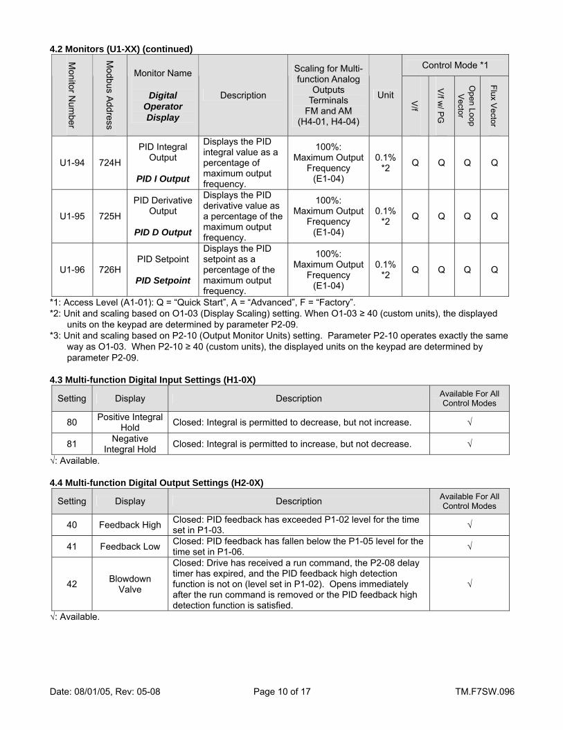
4.2 Monitors (U1-XX) (continued)
Control Mode *1
Monitor N
umber
Modbus A
ddress
Monitor Name
Digital Operator Display
Description
Scaling for Multi-function Analog
Outputs Terminals
FM and AM (H4-01, H4-04)
Unit V/f
V/f w
/ PG
Open Loop V
ector
Flux Vector
U1-94 724H
PID Integral Output
PID I Output
Displays the PID integral value as a percentage of maximum output frequency.
100%: Maximum Output
Frequency (E1-04)
0.1% *2 Q Q Q Q
U1-95 725H
PID Derivative Output
PID D Output
Displays the PID derivative value as a percentage of the maximum output frequency.
100%: Maximum Output
Frequency (E1-04)
0.1% *2 Q Q Q Q
U1-96 726H PID Setpoint
PID Setpoint
Displays the PID setpoint as a percentage of the maximum output frequency.
100%: Maximum Output
Frequency (E1-04)
0.1% *2 Q Q Q Q
*1: Access Level (A1-01): Q = “Quick Start”, A = “Advanced”, F = “Factory”. *2: Unit and scaling based on O1-03 (Display Scaling) setting. When O1-03 ≥ 40 (custom units), the displayed
units on the keypad are determined by parameter P2-09. *3: Unit and scaling based on P2-10 (Output Monitor Units) setting. Parameter P2-10 operates exactly the same
way as O1-03. When P2-10 ≥ 40 (custom units), the displayed units on the keypad are determined by parameter P2-09.
4.3 Multi-function Digital Input Settings (H1-0X)
Setting Display Description Available For All Control Modes
80 Positive Integral Hold Closed: Integral is permitted to decrease, but not increase. √
81 Negative Integral Hold Closed: Integral is permitted to increase, but not decrease. √
√: Available. 4.4 Multi-function Digital Output Settings (H2-0X)
Setting Display Description Available For All Control Modes
40 Feedback High Closed: PID feedback has exceeded P1-02 level for the time set in P1-03. √
41 Feedback Low Closed: PID feedback has fallen below the P1-05 level for the time set in P1-06. √
42 Blowdown Valve
Closed: Drive has received a run command, the P2-08 delay timer has expired, and the PID feedback high detection function is not on (level set in P1-02). Opens immediately after the run command is removed or the PID feedback high detection function is satisfied.
√
√: Available.

Date: 08/01/05, Rev: 05-08 Page 11 of 17 TM.F7SW.096
4.5 Modbus Registers
Modbus Address
Monitor Name Description Unit
024H Output Frequency Output frequency monitor 0.01Hz *4 *4: Scaling based on P2-10 (Output Monitor Units) setting. Parameter P2-10 programs and functions exactly like standard parameter O1-03. 4.6 Faults
Fault Display Description Cause Countermeasures
FRH Feedback Range
High
PID feedback out of range (high). Motor will coast to a stop.
P1-01 = 4 or 5 and the PID feedback has exceeded the P1-02 level for the time set in P1-03.
Correct the cause of the high feedback signal.
FRL Feedback Range
Low
PID feedback out of range (low). Motor will coast to a stop.
P1-01 = 4 or 5 and the PID feedback has fallen below the P1-05 level for the time set in P1-06.
Correct the cause of the low feedback signal.
4.7 Alarms
Alarm Display Description Cause Countermeasures
FRH Feedback Range
High
PID feedback out of range (high)
P1-01 = 2 or 3 and the PID feedback has exceeded the P1-02 level for the time set in P1-03.
Correct the cause of the high feedback signal.
FRL Feedback Range
Low
PID feedback out of range (low)
P1-01 = 2 or 3 and the PID feedback has fallen below the P1-05 level for the time set in P1-06.
Correct the cause of the low feedback signal.
5.0 Function Description
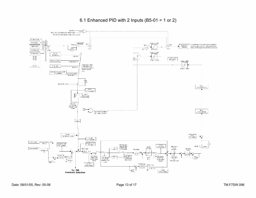
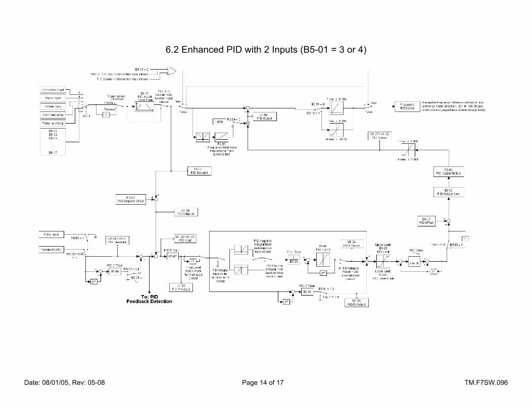
5.1 Enhanced PID The Enhanced PID feature includes many enhancements over the drive’s standard PID function. The PID algorithm is programmed using the existing B5 group of parameters as well as the P group of parameters. See Section 2.0 for details. Enhanced features include: • The ramp in the PID setpoint behaves differently depending upon the PID mode and the reference
source. In most cases, the PID setpoint ramp affects only the PID setpoint. When the PID + Trim feature is enabled (B5-01 = 3 or 4) and there is no independent PID setpoint, the PID ramp affects both the PID setpoint and the frequency reference.
• The PID output is now algebraically summed with the frequency reference. Motor rotation will be forward
if: a forward run is commanded and there is a positive PID + trim, or if a reverse run is commanded and there is a negative PID + trim. Motor rotation will be reverse if: a reverse run is commanded and there is a positive PID + trim, or if a forward run is commanded and there is a negative PID + trim.
• The integral time is lower-limited to the to the PID minimum output limit (P2-01). The integrator is also
held during the sleep mode, and the sleep minimum off time. These changes were done to prevent integrator windup and insure smooth starts with a minimum of pressure overshoot.

Date: 08/01/05, Rev: 05-08 Page 12 of 17 TM.F7SW.096
5.2 Modified PID “Sleep” Function In standard software, parameter B5-16 controls both the sleep delay, and the wake-up delay. In this software, parameter B5-16 controls the sleep delay, and P2-06 controls the wake-up delay. The maximum settable range of B5-16 is increased from 25.5 seconds to 600.0 seconds. An additional timer has been added (P2-07) to the sleep function to insure that when the drive does go into the sleep mode, it remains in sleep mode even if the PID is calling for the drive to run. This is to insure that the pressure in the “sump” of the air compressor can dissipate before it restarts. This prevents foaming of the oil.
5.3 Blowdown Valve Digital Output
This digital output can be used to control the blowdown or loading valve for the air compressor. When this output is energized, the blowdown valve is active, and the compressor is allowed to make air. If this output is de-energized, the air compressor won’t produce any air, even if it is turning. This output should normally be energized when the drive is running, but only after a delay after startup (determined by parameter number P2-08). This allows the motor, drive, and compressor to start under less load. The output will also de-energize if the PID feedback (air pressure) goes too high. The level, time delays, and hysteresis share the same parameters as the PID feedback high detection alarm and fault. (P1-02, P1-03, P1-04, and P1-08). See Section 6.5 for a detailed block diagram.
5.4 Customized Display of Keypad Monitors
When first powered up (or returning to the drive mode), the digital operator display will show pressure setpoint (U1-01), pressure feedback (U1-90), and output frequency (U1-02). All PID setpoints (U1-01, D1-XX) and PID monitors (U1-9X) have user selectable scaling (O1-03) and keypad display units (P2-09). User selectable units will only be displayed when O1-03 ≥ 40 (custom units). Unit selections are PSI, kPa, and oF. Other parameters that are normally scaled using O1-03, which include U1-02, U1-05, U1-20, and U1-46, are scaled by parameter P2-10. Parameter P2-10 will work in exactly the same manner as O1-03 does. When the setting is 0, the units and scaling will be in 0.01Hz. When the setting is 1, the units and scaling will be in 0.01%. When the setting is 2 ~ 38, the scaling will be in RPM, with the setting of P2-10 acting as the number of motor poles for the calculation. When the P2-10 ≥ 40 (custom scaling), the keypad display units are determined by parameter P2-09. Unit selections are PSI, kPa, and oF.
6.0 Block Diagrams
The following pages give detailed flowcharts of the following software functions: 6.1 PID with 2 Inputs (B5-01 = 1 or 2) 6.2 PID with 2 Inputs (B5-01 = 3 or 4) 6.3 PID with 3 Inputs (B5-01 = 3 or 4) 6.4 PID Feedback Detection 6.5 PID Sleep function and Blowdown Valve Digital Output
U1-01
U1-90
U1-02
U1-03
U1-94
U1-96
.
.
.
U1-93
U1-92
U1-91
U1-95
Date: 08/01/05, Rev: 05-08 Page 13 of 17 TM.F7SW.096
6.1 Enhanced PID with 2 Inputs (B5-01 = 1 or 2)
Date: 08/01/05, Rev: 05-08 Page 14 of 17 TM.F7SW.096
6.2 Enhanced PID with 2 Inputs (B5-01 = 3 or 4)

Date: 08/01/05, Rev: 05-08 Page 15 of 17 TM.F7SW.096
6.3 Enhanced PID with 3 Inputs (B5-01 = 3 or 4)
Date: 08/01/05, Rev: 05-08 Page 16 of 17 TM.F7SW.096
6.4 Enhanced PID Feedback Detection

Date: 08/01/05, Rev: 05-08 Page 17 of 17 TM.F7SW.096
6.5 PID Sleep Function and Blowdown Valve Digital Output