Enhanced Easy-Stop TM Trailer ABS Training. Enhanced Easy-Stop Trailer ABS System configurations to...
32
Enhanced Easy- Stop TM Trailer ABS Training
-
Upload
tayler-oldford -
Category
Documents
-
view
222 -
download
0
Transcript of Enhanced Easy-Stop TM Trailer ABS Training. Enhanced Easy-Stop Trailer ABS System configurations to...
Enhanced Easy-StopTM Trailer ABS
Enhanced Easy-StopTM Trailer ABS
Training
Enhanced Easy-StopTrailer ABS
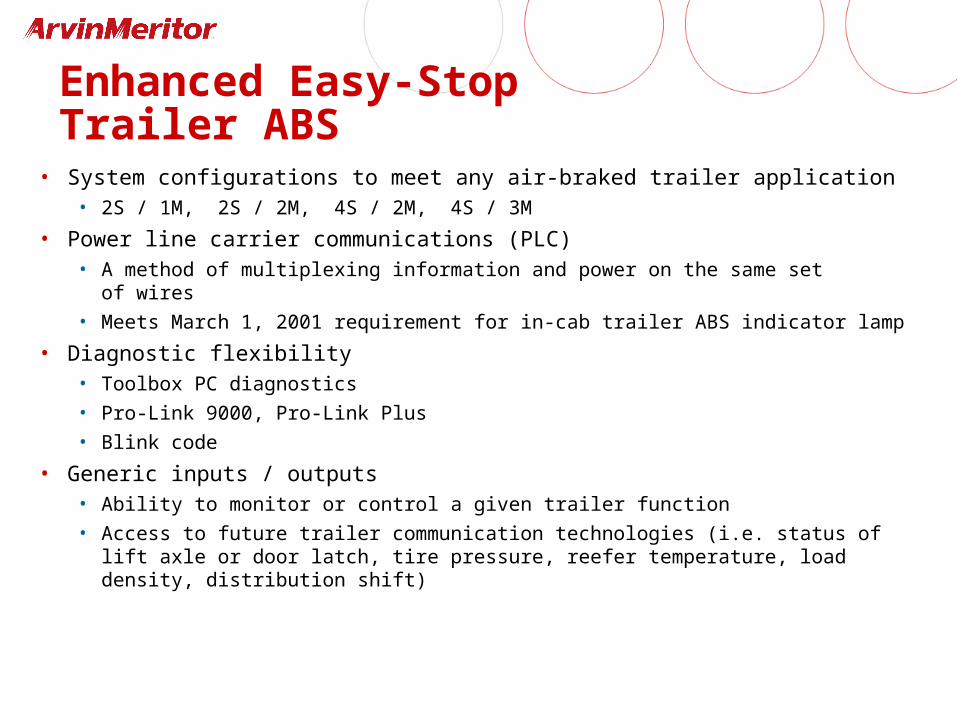
• System configurations to meet any air-braked trailer application• 2S / 1M, 2S / 2M, 4S / 2M, 4S / 3M
• Power line carrier communications (PLC)• A method of multiplexing information and power on the same set
of wires
• Meets March 1, 2001 requirement for in-cab trailer ABS indicator lamp
• Diagnostic flexibility• Toolbox PC diagnostics
• Pro-Link 9000, Pro-Link Plus
• Blink code
• Generic inputs / outputs• Ability to monitor or control a given trailer function
• Access to future trailer communication technologies (i.e. status of lift axle or door latch, tire pressure, reefer temperature, load density, distribution shift)
Enhanced Easy-StopTrailer ABS
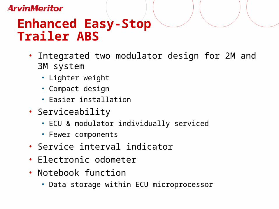
• Integrated two modulator design for 2M and 3M system• Lighter weight
• Compact design
• Easier installation
• Serviceability• ECU & modulator individually serviced
• Fewer components
• Service interval indicator
• Electronic odometer
• Notebook function• Data storage within ECU microprocessor
Enhanced Easy-StopTrailer ABS
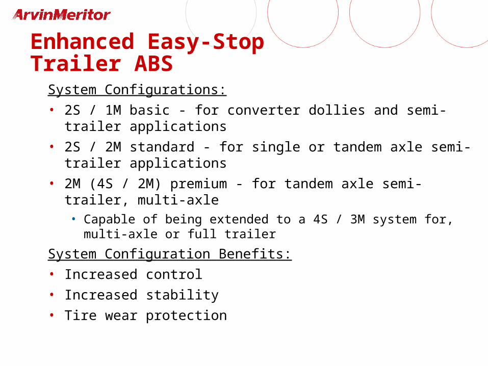
System Configurations:
• 2S / 1M basic - for converter dollies and semi-trailer applications
• 2S / 2M standard - for single or tandem axle semi-trailer applications
• 2M (4S / 2M) premium - for tandem axle semi-trailer, multi-axle• Capable of being extended to a 4S / 3M system for, multi-axle or
full trailer
System Configuration Benefits:
• Increased control
• Increased stability
• Tire wear protection
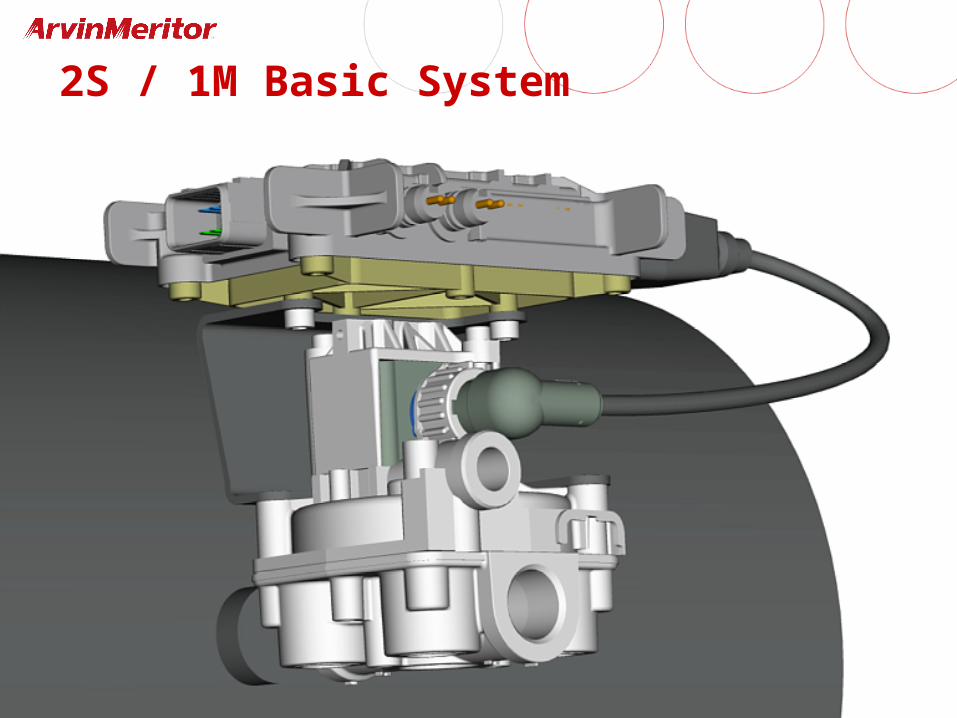
New Items2S / 1M Basic System
• 4x2 electrical connections (2)• Electrical connection for solenoid is external
• Combination power / diagnostic connector• Optional power / diagnostics cable or power-only cable
• One generic I / O available
• 3/8" control port vs. previous model 1/4"
• Serviceability
• Can be installed as complete assembly or mounted separately (longer valve cable)
• Elimination of LED on top of ECU
2S / 1M Basic System
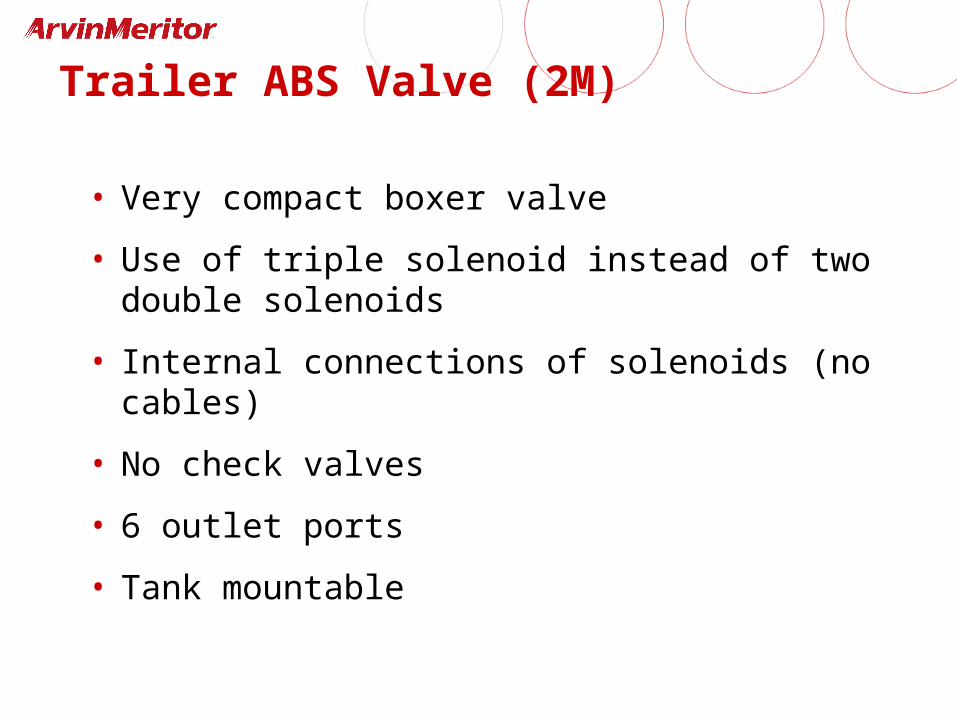
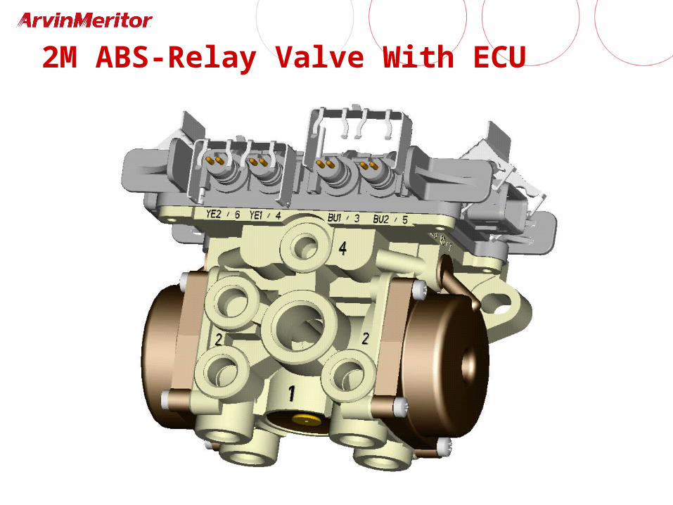
Trailer ABS Valve (2M)
• Very compact boxer valve
• Use of triple solenoid instead of two double solenoids
• Internal connections of solenoids (no cables)
• No check valves
• 6 outlet ports
• Tank mountable
2S / 2M Standard System
• 2S / 2M only
• One 4x2 electrical connection for power / diagnostics• One generic I / O available
• Dual modulator assembly• Internal electrical solenoid connection
• 1/4" control line
• Serviceable
• Elimination of LED on top of ECU
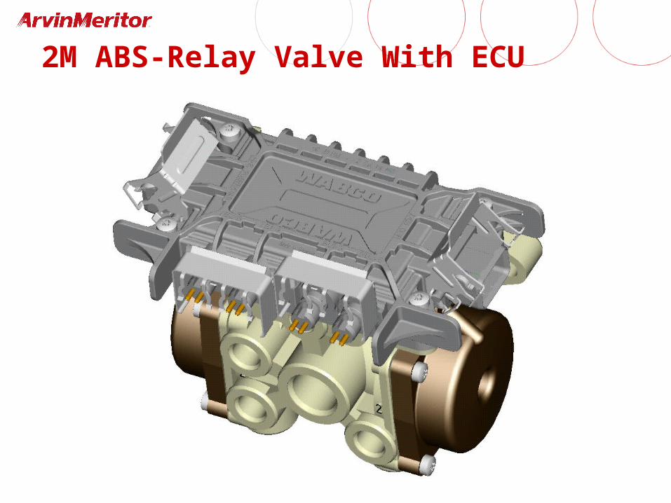
2M ABS-Relay Valve With ECU
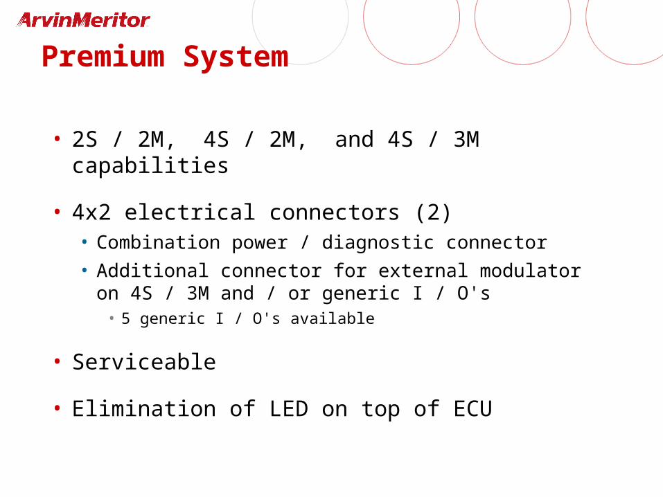
Premium System
• 2S / 2M, 4S / 2M, and 4S / 3M capabilities
• 4x2 electrical connectors (2)• Combination power / diagnostic connector
• Additional connector for external modulator on 4S / 3M and / or generic I / O's
• 5 generic I / O's available
• Serviceable
• Elimination of LED on top of ECU
2M ABS-Relay Valve With ECU
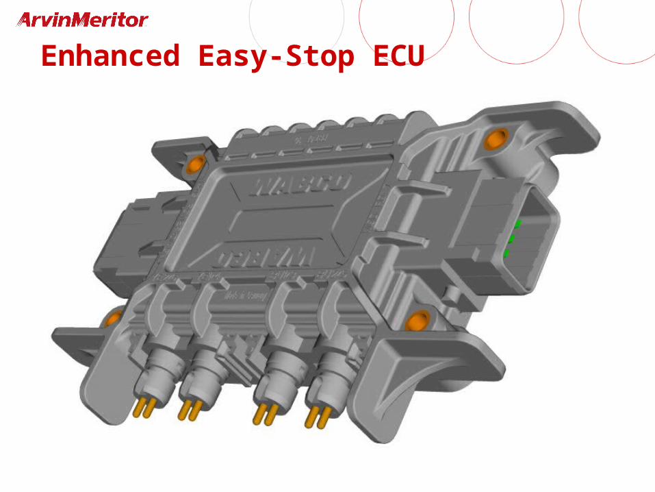
Enhanced Easy-Stop ECU
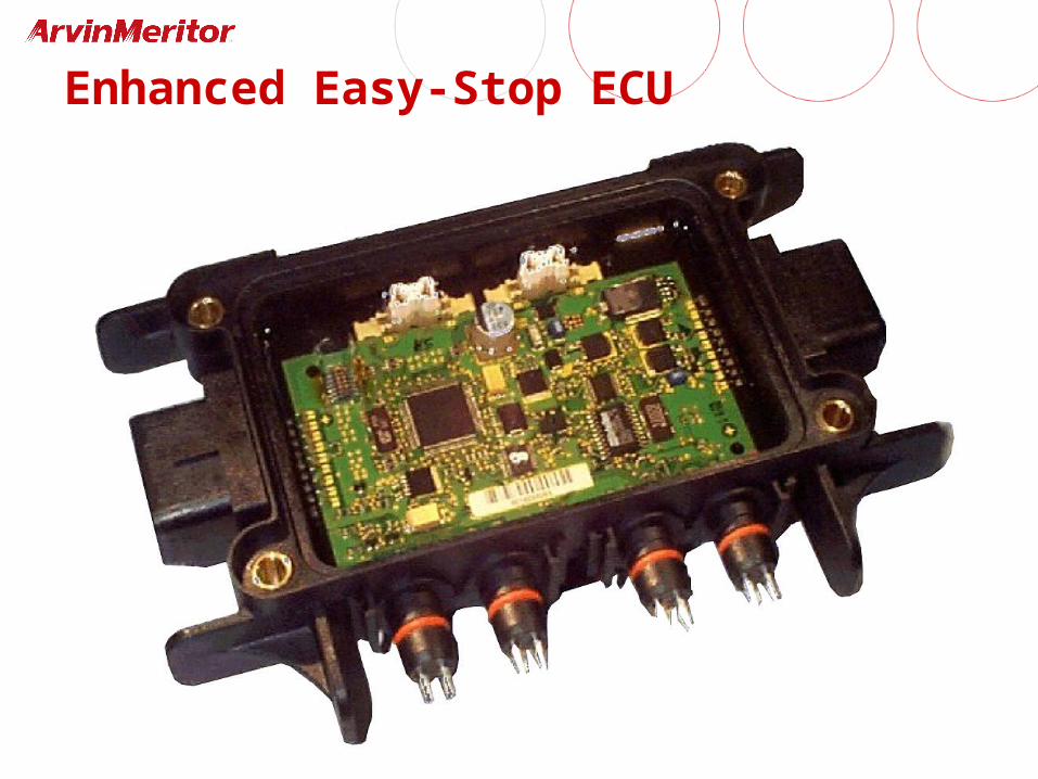
Enhanced Easy-Stop ECU
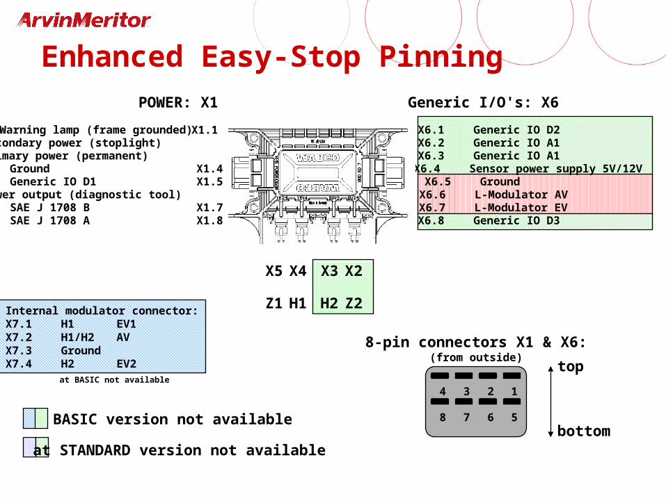
Warning lamp (frame grounded) Secondary power (stoplight) X1.2Primary power (permanent) X1.3Ground X1.4Generic IO D1 X1.5Power output (diagnostic tool) X1.6SAE J 1708 B X1.7SAE J 1708 A X1.8
POWER: X1
H1 H2 Z2Z1
at BASIC version not available
X6.1 Generic IO D2X6.2 Generic IO A1X6.3 Generic IO A1X6.4 Sensor power supply 5V/12VX6.5 GroundX6.6 L-Modulator AVX6.7 L-Modulator EVX6.8 Generic IO D3
X5 X4 X3 X2
Generic I/O's: X6
4 3 2 1
8 7 6 5
8-pin connectors X1 & X6:(from outside)
Internal modulator connector:X7.1 H1 EV1X7.2 H1/H2 AV X7.3 GroundX7.4 H2 EV2 top
bottomat STANDARD version not available
at BASIC not available
Enhanced Easy-Stop Pinning
X1.1
YE2
YE1
supply line
air tank
control line
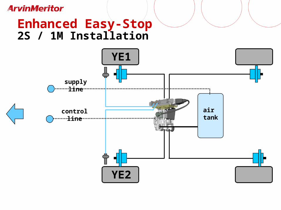
Enhanced Easy-Stop2S / 1M Installation
YE1
YE2
supply line
air tankcontrol line
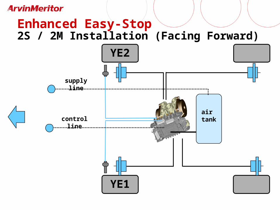
Enhanced Easy-Stop2S / 2M Installation (Facing Forward)
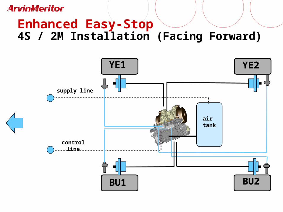
Enhanced Easy-Stop4S / 2M Installation (Facing Forward)
YE1 YE2
BU1 BU2
supply line
air tank
control line
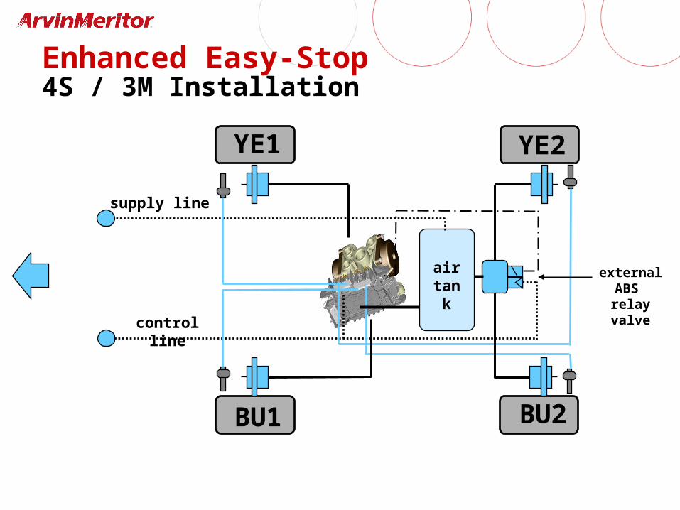
YE1 YE2
BU1 BU2
supply line
air tank
control line
external ABS relay valve
Enhanced Easy-Stop4S / 3M Installation
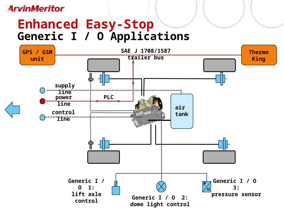
TCS II
supply line
air tankcontrol line
power line PLC
SAE J 1708/1587 trailer bus ThermoKing
GPS / GSMunit
Pu
Generic I / O 1:lift axle control
Generic I / O 2:dome light control
Generic I / O 3:pressure sensor
Enhanced Easy-StopGeneric I / O Applications
Power Line Communications
Background:
• Requirement: • Need to communicate information between tractor and
trailer
• FMVSS 121 requirement for in-cab trailer ABS indicator lamp by March 1, 2001
• Fleets strongly oppose changing existing J560 connector or adding another
• Solution: • Power line carrier communications (PLC)
• Industry group: PCL4trucks
Power Line Communications
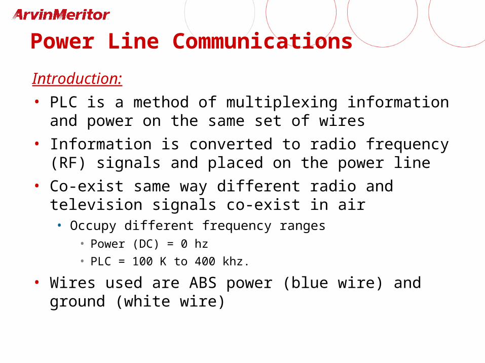
Introduction:
• PLC is a method of multiplexing information and power on the same set of wires
• Information is converted to radio frequency (RF) signals and placed on the power line
• Co-exist same way different radio and television signals co-exist in air• Occupy different frequency ranges
• Power (DC) = 0 hz
• PLC = 100 K to 400 khz.
• Wires used are ABS power (blue wire) and ground (white wire)
Power Line Communications
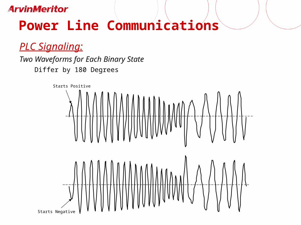
PLC Signaling:Two Waveforms for Each Binary State
Differ by 180 Degrees
Starts Positive
Starts Negative
Power Line Communications
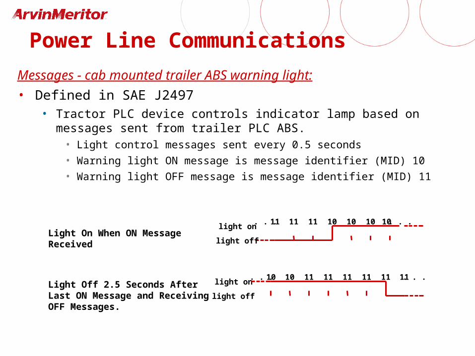
Messages - cab mounted trailer ABS warning light:
• Defined in SAE J2497• Tractor PLC device controls indicator lamp based on messages sent from
trailer PLC ABS.• Light control messages sent every 0.5 seconds
• Warning light ON message is message identifier (MID) 10
• Warning light OFF message is message identifier (MID) 11
. . .11 11 11 10 10 10 10 . . .light on
light offLight On When ON Message Received
Light Off 2.5 Seconds After Last ON Message and Receiving OFF Messages.
11
light off
light on. . .10 10 11 11 11 11 11. . .
Diagnostics
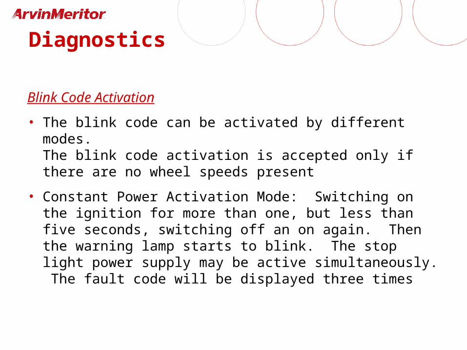
Blink Code Activation
• The blink code can be activated by different modes.The blink code activation is accepted only if there are no wheel speeds present
• Constant Power Activation Mode: Switching on the ignition for more than one, but less than five seconds, switching off an on again. Then the warning lamp starts to blink. The stop light power supply may be active simultaneously. The fault code will be displayed three times
Diagnostics
Blink Code Activation (cont'd.)
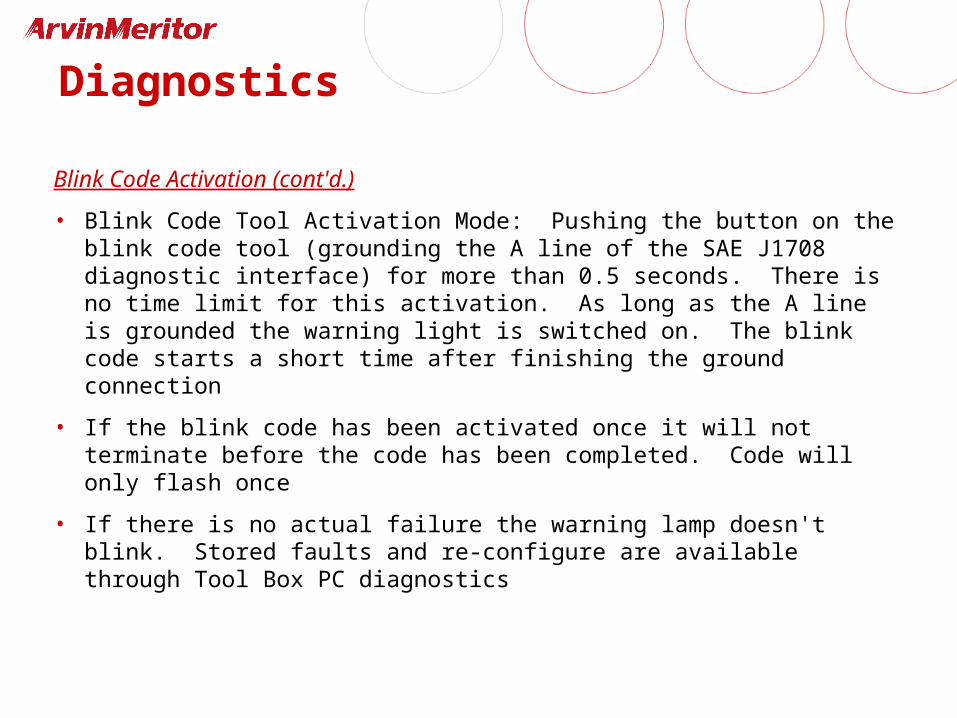
• Blink Code Tool Activation Mode: Pushing the button on the blink code tool (grounding the A line of the SAE J1708 diagnostic interface) for more than 0.5 seconds. There is no time limit for this activation. As long as the A line is grounded the warning light is switched on. The blink code starts a short time after finishing the ground connection
• If the blink code has been activated once it will not terminate before the code has been completed. Code will only flash once
• If there is no actual failure the warning lamp doesn't blink. Stored faults and re-configure are available through Tool Box PC diagnostics
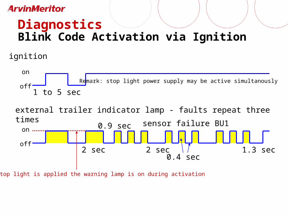
ignition
external trailer indicator lamp - faults repeat three times
on
off
on
off
1 to 5 sec
2 sec
sensor failure BU1
0.4 sec
Remark: stop light power supply may be active simultanously
2 sec
0.9 sec
If stop light is applied the warning lamp is on during activation
1.3 sec
DiagnosticsBlink Code Activation via Ignition
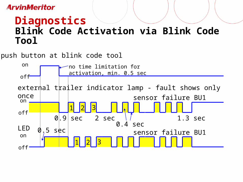
1
push button at blink code tool
external trailer indicator lamp - fault shows only once
on
off
on
off
sensor failure BU1
0.4 secLEDon
off
2 sec0.9 sec
no time limitation for activation, min. 0.5 sec
1.3 sec
0.5 sec
2 3
1 2 3
DiagnosticsBlink Code Activation via Blink Code Tool
sensor failure BU1
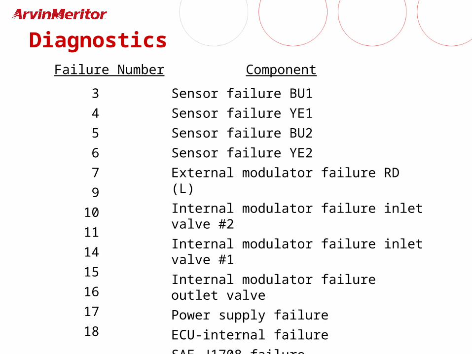
DiagnosticsFailure Number Component
3
4
5
6
7
9
10
11
14
15
16
17
18
Sensor failure BU1
Sensor failure YE1
Sensor failure BU2
Sensor failure YE2
External modulator failure RD (L)
Internal modulator failure inlet valve #2
Internal modulator failure inlet valve #1
Internal modulator failure outlet valve
Power supply failure
ECU-internal failure
SAE J1708 failure
SAE J2497 failure
Generic I.O. failure
Diagnostics
• Sensor gap faults• Following a sensor gap fault, upon power up, after
adjusting sensor, the light will come on and stay on until the ECU detects wheel speed
• All other sensor faults• Once fixed, all other sensor faults (i.e. breaks, loose
connections) upon power up will execute a normal bulb check without wheel speed input needed
• Sensor resistances should be between 900-2000 ohms
Sensor Adjustment
• Self adjusting• Push sensor in until you have contact with tooth
wheel
• Wheel end play will push sensor away from tooth wheel
• Required gap of .040 or less
• Wheel bearing adjustment must be within spec (0 to .005 run-out) to maintain proper sensor adjustment
Diagnostic Tools
• Blink code• Single integer fault codes, eliminates expert mode
• Automatic clearing of faults after 1,000 power-ups or 250 hours of operation
• Warning lamp vs. blink code tool sequence
• Pro-Link• No significant changes to functionality
• Tool Box PC diagnostics
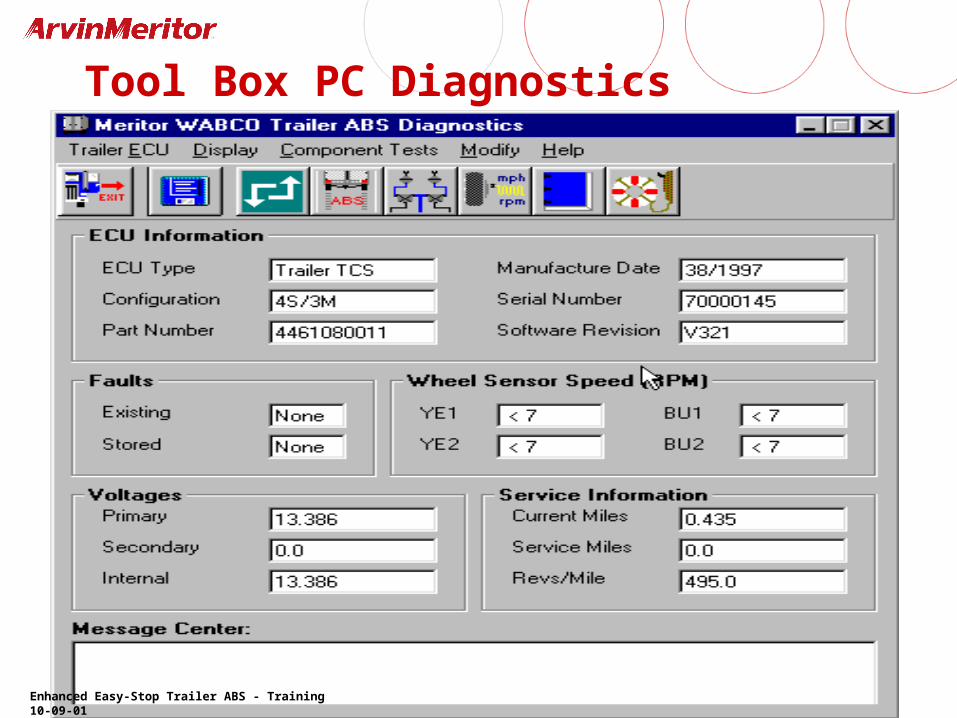
Tool Box PC Diagnostics
Enhanced Easy-Stop Trailer ABS - Training 10-09-01