ENGR-2300 Electronic Instrumentation Quiz 1 Spring 2015 · ENGR-2300 . Electronic Instrumentation ....
15
ENGR-2300 Quiz 1 Spring 2015 1 K. A. Connor ENGR-2300 Electronic Instrumentation Quiz 1 Spring 2015 On all questions: SHOW ALL WORK. BEGIN WITH FORMULAS, THEN SUBSTITUTE VALUES AND UNITS. No credit will be given for numbers that appear without justification. Read the entire quiz before answering any questions. Also it may be easier to answer parts of questions out of order.
Transcript of ENGR-2300 Electronic Instrumentation Quiz 1 Spring 2015 · ENGR-2300 . Electronic Instrumentation ....

ENGR-2300 Quiz 1 Spring 2015
1 K. A. Connor
ENGR-2300
Electronic Instrumentation
Quiz 1
Spring 2015
On all questions: SHOW ALL WORK. BEGIN WITH FORMULAS, THEN SUBSTITUTE VALUES AND UNITS. No credit will be given for numbers that appear without justification. Read the entire quiz before answering any questions. Also it may be easier to answer parts of questions out of order.

ENGR-2300 Quiz 1 Spring 2015
2 K. A. Connor
The School of Engineering started with 75 students in 1990/91 and currently offers associate degrees in technology, baccalaureate programs in Mechanical Engineering, Electrical Engineering, Computer Engineering, Civil Engineering (as of 2013) and Industrial Management Engineering, and Masters in Administration of Telecommunications and Network Systems and in Mechanical Engineering with concentrations in Alternative Energy and Aerospace Engineering. Presently, the School has 500 students in Associate Degree Programs, 900 in Bachelor Degree Programs and 50 in Masters Programs.
Workshop: Diffusion of Hands-On Learning in Puerto Rico Using the Analog Discovery Board Date: 21 February 2015 The workshop was attended by about two dozen professors from essentially all Puerto Rican engineering schools. Included in the participant list were RPI graduates. The workshop was organized by Prof Juan Morales, head of Mechanical Eng at Turabo and his colleagues Mary Ruales (ME) and Idalides Vergara-Laurens (Computer Eng). It was led by me (KC) and Prof. Yacob Astatke from Morgan State University. It was 85 degrees but rained a little. Nice change from Troy. As is typically the case in these workshops, you all pick up how to use the equipment faster than most professors. However, they rapidly came up to speed and had lots of fun.

ENGR-2300 Quiz 1 Spring 2015
3 K. A. Connor
Analog Discovery Connections
ENGR-2300 Quiz 1 Spring 2015
4 K. A. Connor

ENGR-2300 Quiz 1 Spring 2015
5 K. A. Connor
I. Voltage Dividers (20 points)
a) Find the voltage Vout in the circuit below. (4 pts)
798.622166.9
61616
≈==+
= inout VV
b) Find the current I in resistor R1. (4 pts)
mAI 44.06/6.2 ==
c) 100W incandescent lightbulbs were banned in 2012 (followed soon by 75W, 60W, and 40W bulbs) because only about 5% of the energy they use comes out as light. They are mostly heat producers. Since 20% of the energy we use goes to lighting our homes and businesses, the impact of this ban is potentially very great. Basically, a traditional lightbulb is just a resistor that gives off a little light. How large is that resistance? At 120V, PVR 2= where P is average power. (120V is an RMS AC voltage, which is what we use to obtain average power for an AC signal.) Then,
Ω== 1441001202R . You decide to measure the resistance, but you do not have a Multimeter so you use a voltage divider configured with a Heavy Duty 9V battery, a
Vin1
9Vdc
R3
Rbulb
0
Vout2
Ground2
Rbat
Vin
9.6Vdc
R16k
R216k
0
Vout
Ground

ENGR-2300 Quiz 1 Spring 2015
6 K. A. Connor
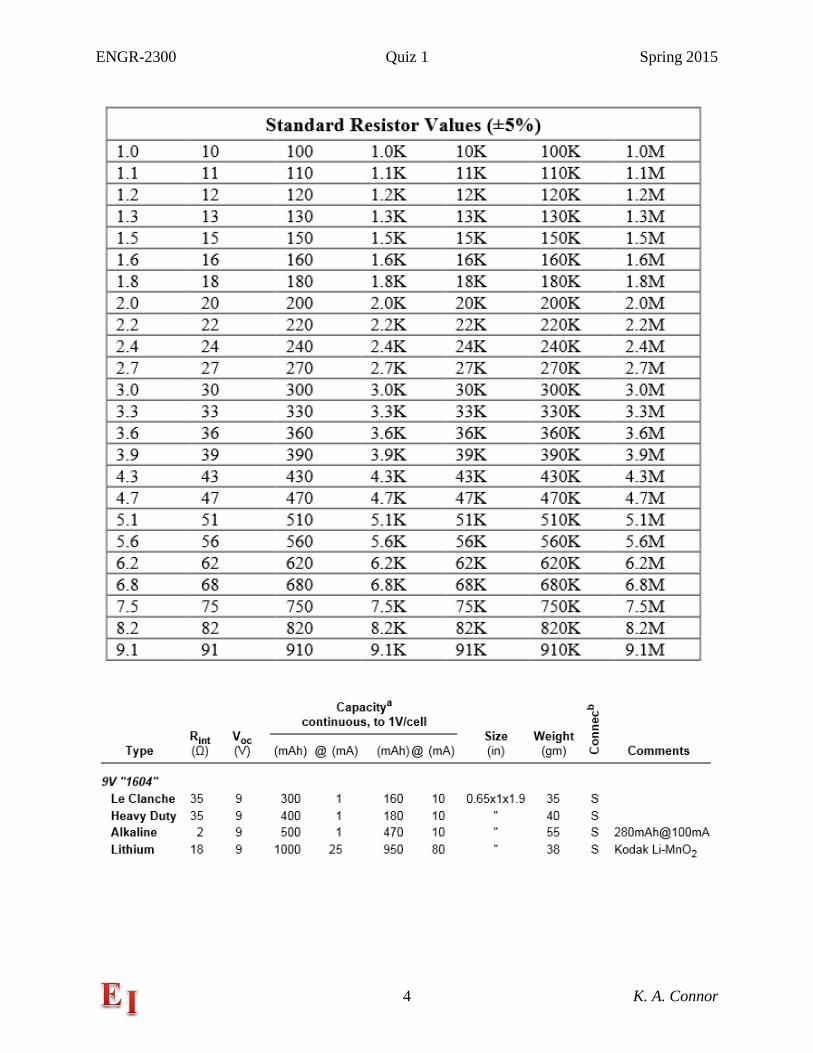
standard resistor and the bulb. Using the standard resistance that is closest in value to 144Ω, you measure an output voltage of 0.4V. Using this information, find the value of the bulb resistance. This is called the cold resistance, because the bulb will not be turned on at these low voltages. Hint: Be sure to check the additional information provided with this quiz. (8 pts) Rbat = 35 Ohms, closest R to 144 is 150 Ohms
RR
++=
1503594.0 then solve for R= 8.6 Ohms (5% error OK)
d) To do the cold resistance measurement experiment, you must be sure that the standard resistor you use can handle enough power. Which of the following types of resistors will work in this experiment? Determine the power delivered to resistor R3 and then circle all possible answers. (4 pts) 1/4W 1/2W 1W 2W
The current is 0.4/8.6 = 47mA
mWRI 3242 = so the quarter Watt resistor will not work, but the other three will.

ENGR-2300 Quiz 1 Spring 2015
7 K. A. Connor
II. Resistor Combinations (20 points)
One of the important things you should learn about electronics is to never throw away a power supply from obsolete or broken equipment. For example, a power supply for HP printers outputs 32V or 16V DC. Assume you have such a supply and build the resistor ladder circuit shown above to provide a series of reference voltages.
10k+10k = 20k
20k||20k = 10k
H is middle of voltage divider
Made with two 10k resistors
Voltage at I is also half H
G: 32V H: 16V I: 8V
V132Vdc
R1
10k
R2
10k
R3
10k
R4
10k
R5
10k
R620k
R720k
R820k
R920k
R1010k
0
BA DC FE
V232Vdc
R11
10k
R12
10k
R1620k
R1710k
0
G IH
ENGR-2300 Quiz 1 Spring 2015
8 K. A. Connor
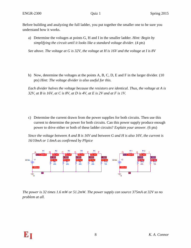
Before building and analyzing the full ladder, you put together the smaller one to be sure you understand how it works.
a) Determine the voltages at points G, H and I in the smaller ladder. Hint: Begin by simplifying the circuit until it looks like a standard voltage divider. (4 pts)
See above. The voltage at G is 32V, the voltage at H is 16V and the voltage at I is 8V
b) Now, determine the voltages at the points A, B, C, D, E and F in the larger divider. (10 pts) Hint: The voltage divider is also useful for this.
Each divider halves the voltage because the resistors are identical. Thus, the voltage at A is 32V, at B is 16V, at C is 8V, at D is 4V, at E is 2V and at F is 1V.
c) Determine the current drawn from the power supplies for both circuits. Then use this current to determine the power for both circuits. Can this power supply produce enough power to drive either or both of these ladder circuits? Explain your answer. (6 pts)
Since the voltage between A and B is 16V and between G and H is also 16V, the current is 16/10mA or 1.6mA as confirmed by PSpice
The power is 32 times 1.6 mW or 51.2mW. The power supply can source 375mA at 32V so no problem at all.

ENGR-2300 Quiz 1 Spring 2015
9 K. A. Connor
III. Filters & Transfer Functions (20 points)
a) Shown above are the four basic, two-element, passive filter configurations made with RL and RC combinations. Determine the general complex transfer function for each circuit in terms of R, L, C and frequency ω, by modeling each as a voltage divider. (4 pts)
A) RL: LjR
LjVV
VV
IN
OUT
ωω+
==12
34 B) RC: RCjCjR
CjVV
VV
IN
OUT
ωω
ω+
=+
==1
11
1
12
34
C) LR: LjR
RVV
VV
IN
OUT
ω+==
12
34 D) CR: RCj
RCj
CjRR
VV
VV
IN
OUT
ωω
ω+
=+
==1112
34
Either form of the solutions is OK.
A B
C D
1
2
3
4
1
2
3
4
1
2
3
4
1
2
3
4

ENGR-2300 Quiz 1 Spring 2015
10 K. A. Connor
b) Assume all four circuits are made with ideal components. Identify which are high pass filters and which are low pass filters by circling the high pass and underlining the low pass in the following list (4 pts): RC CR RL LR
c) Assume that one of the four circuits is enclosed in an unmarked, black box, like the one shown at the left. That is, we know that the box contains one of the circuits and decide to
make a series of measurements to identify which one it is by making various connections with the inputs and outputs. We first try the identification by making the DC resistance measurements listed in the table below. Identify the circuit tested by adding its name to the table in the column labeled Circuit. Explain your answer. Hint: The R, L & C are realistic circuit components and, thus, are not necessarily represented by just their ideal circuit elements. (4 pts)
R12 R13 R34 R24 Circuit R12 SC Load 1.1kΩ 100Ω 1kΩ 0 C or LR 100 Ohms
Explanation: At DC treat the inductor as a 100Ohm resistor. Then it is a voltage divider.
d) What input resistance R12 would be measured when the load is a short circuit (SC)? Add your answer to the table. (4 pts)
See table.
e) A function generator (amplitude = 1V) is connected to the input of the circuit and the output voltage is measured as a function of frequency. The frequency of the function generator is changed and the phase shift between the input and output voltage is measured, as shown in the table below.
Phase Shift 0 Deg -15 Deg -30 Deg -45 Deg -60 Deg -75 Deg -90 Deg Frequency 30Hz 4.7kHz 10.3kHz 17.6kHz 30.4kHz 65.5kHz 10MHz
From the information in the table, determine the value of the inductance L or capacitance C for the circuit. (4 pts)
The phase shift at the corner frequency is 45 degrees. Thus the corner freq is 17.6kHz or ω is
110,584. mHRLc
101105841100
===ω

ENGR-2300 Quiz 1 Spring 2015
11 K. A. Connor
IV – Signals, Transformers and Inductors (20 points)
Given the circuit above, assume an ideal transformer with full coupling. In your answers to the following questions, use all available and useful information.
a) For the given information, write out the expressions for the ratios Vout/Vin, Iout/Iin and the transformer input impedance Rin. (6 pts)
out
in
in
out
II
VV
NN
mHmHa =====
1
2
101
5005 or
in
out
II
=10 and
Ω== 6500100 2RZin
b) Draw the circuit diagram for the voltage divider consisting of the transformer input impedance Rin and the resistance R1. Then solve for Vin, the voltage across the input terminals of the ideal transformer. (4 pts)
Because the Zin is 6.5kΩ and the other resistor is 35Ω, essentially all of the voltage appears across Zin so Vin is 1824V.
V1
FREQ = 30kHz
AC = 1824V
R1
35
R265
0
TX1
L1_VALUE = 500mH L2_VALUE = 5mH
VoutVin
ENGR-2300 Quiz 1 Spring 2015
12 K. A. Connor
c) Find Vout from your value for Vin. (3 pts)
Vout is 10 times smaller so it is 182.4V
d) Determine both the primary and secondary currents (I1 and I2). (4 pts)
This can be done several ways, but the easiest is Iin is 1824/6500) or 280mA and Iout is 10 times larger or 2.8A.
e) Determine the power delivered to the load R2. (3 pts)
182.4(2.8) = 510W (actually 506.4W with nothing rounded off) 5% error OK.
f) What is the significance of the number 1824 in the history of RPI? What is the significance of the number 35 in the history of RPI? (Up to 2 pts extra credit)
RPI was founded in 1824 and the 1985 men’s RPI hockey team had 35 wins in its national championship season. Actually, any clever answer for 35 will be accepted, but 1824 must be correct.
ENGR-2300 Quiz 1 Spring 2015
13 K. A. Connor
V – Misc & Concepts (20 points)
The following questions all come from the daily videos and were asked at the beginning of class.
The answers for all questions are worth (1 pt) each, except where noted.
a) What are the colors & names of the two wires for ‘Scope Ch1?
Orange/1+ and Orange with white stripe/1-
b) What are the colors & names of the two wires for ‘Scope Ch2?
Blue/2+ and Blue with white stripe/2-
c) What are the colors & names of the two wires for Arbitrary Waveform Generator (AWG) 1?
This one is a little tricky. Yellow/W1 for one wire and Black/Ground for the other
d) Is it always necessary to measure both the input and output voltage or current for every circuit studied?
Yes.
e) In a resistive voltage divider, will the output voltage always be less than the input?
Lower because the output is taken across only one of the two resistors
f) What is the input impedance of an Analog Discovery scope channel?
1 M Ohms
g) What is a typical internal resistance for a 9V heavy duty battery?
30-40 Ohms
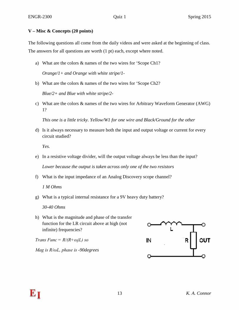
h) What is the magnitude and phase of the transfer function for the LR circuit above at high (not infinite) frequencies?
Trans Func = R/(R+ωjL) so
Mag is R/ωL, phase is -90degrees

ENGR-2300 Quiz 1 Spring 2015
14 K. A. Connor
i) What is meant by a low frequency or a high frequency when dealing with RC, RL or RLC circuits? (3 pts) Be specific for each configuration.
i. RC R << 1/(ωC) for low (other direction for high)
ii. RL R >> ωL for low (other direction for high)
iii. RLC for low, both low conditions above … or high, other set
j) In the CR circuit above, is the current in R large or small when the frequency is low?
Low frequency, C is open, current is small.
k) What is the purpose of an ideal model for an inductor if the analytical formula we can derive from it does not provide a particularly accurate prediction of inductance?
It is used to estimate inductance values so other circuit parameters can be selected to be near what is needed.
l) What could you do to improve the coupling of your transformer so that it will work equally well in both step up and step down modes?
Either wind the two coils to be the same length or wind them on a magnetic core. Either answer is OK
ENGR-2300 Quiz 1 Spring 2015
15 K. A. Connor
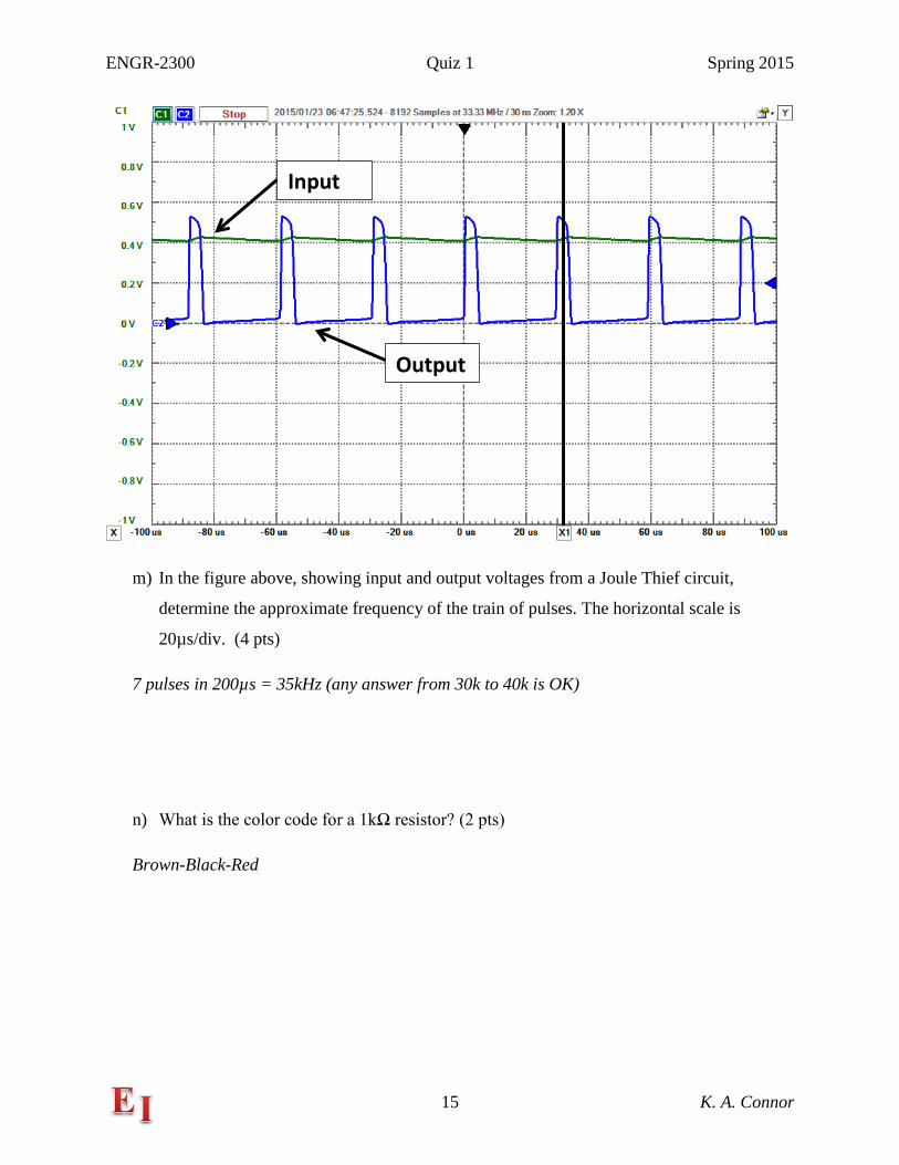
m) In the figure above, showing input and output voltages from a Joule Thief circuit,
determine the approximate frequency of the train of pulses. The horizontal scale is
20µs/div. (4 pts)
7 pulses in 200µs = 35kHz (any answer from 30k to 40k is OK)
n) What is the color code for a 1kΩ resistor? (2 pts)
Brown-Black-Red
Input
Output