
ENGR 224 - Thermodynamics Baratuci HW #4 Problem : 6.79 - … · 2011-05-05 · The 1st Carnot...
18
Baratuci HW #4 Problem : 6.79 - Effect of Source and Sink Temperatures on HE Efficiency - 6 pts 5-May-11 Read : Given : Q H 65000 kJ/min b.) T C 25 o C a.) T C 0 o C T H {0…50} o C T H {300…1000} o C c.) T C 50 o C T H {0…50} o C Find : a.) b.) c.) Assumptions : Diagram : Equations / Data / Solve : The equation for the thermal efficiency of a Carnot Cycle is : Eqn 1 A Carnot Cycle yields the maximum thermal efficiency for a HE. Eqn 2 Eqn 3 Solving for the maximum power output yields : Eqn 4 Now, we have all the equations we need to construct the plots for parts (a), (b) and (c). A Carnot Heat Engine produces the maximum power for a given heat input and also has the maximum thermal efficiency. So, this problem is really all about the Carnot HE Efficiency. We are given both reservoir temperatures and asked to construct plots of the power output and thermal efficiency as functions of reservoir temperatures. This will only require that we apply the 1st Law and the equation for the efficiency of a Carnot HE. No problem. - The heat source and heat sink behave as true thermal reservoirs. Their temperatures remain constant regardless of how much is transferred into or out of them. ENGR 224 - Thermodynamics A heat engine operates between a source at T H and a sink at T C . Heat is supplied to the heat engine at a steady rate of 65,000 kJ/min. Study the effects of T H and T C on the maximum power produced and the maximum cycle efficiency. For T C = 0, 25 and 50 o C, let T H vary from 300 o C to 1000 o C. Create plots of W cycle and η th as functions of T H . Discuss the results. The maximum thermal efficiency also produces the maximum power. We can calculate this using the definition of the thermal efficiency of a HE and applying it to a Carnot HE. Construct plots of W cycle and th as a functions of T H . Construct plots of W cycle and th as a functions of T H . Construct plots of W cycle and th as a functions of T H . C th,Carnot H T 1 T cycle th H W Q max th,Carnot H W Q max H th,Carnot W Q Dr. Baratuci - ENGR 224 hw4-sp11.xlsm , 6.79 5/5/2011
Transcript of ENGR 224 - Thermodynamics Baratuci HW #4 Problem : 6.79 - … · 2011-05-05 · The 1st Carnot...
BaratuciHW #4
Problem : 6.79 - Effect of Source and Sink Temperatures on HE Efficiency - 6 pts 5-May-11
Read :
Given : QH 65000 kJ/min b.) TC 25oC
a.) TC 0oC TH {0…50}
oC
TH {300…1000}oC c.) TC 50
oC
TH {0…50}oC
Find : a.)
b.)
c.)
Assumptions :
Diagram :
Equations / Data / Solve :
The equation for the thermal efficiency of a Carnot Cycle is : Eqn 1
A Carnot Cycle yields the maximum thermal efficiency for a HE.
Eqn 2 Eqn 3
Solving for the maximum power output yields : Eqn 4
Now, we have all the equations we need to construct the plots for parts (a), (b) and (c).
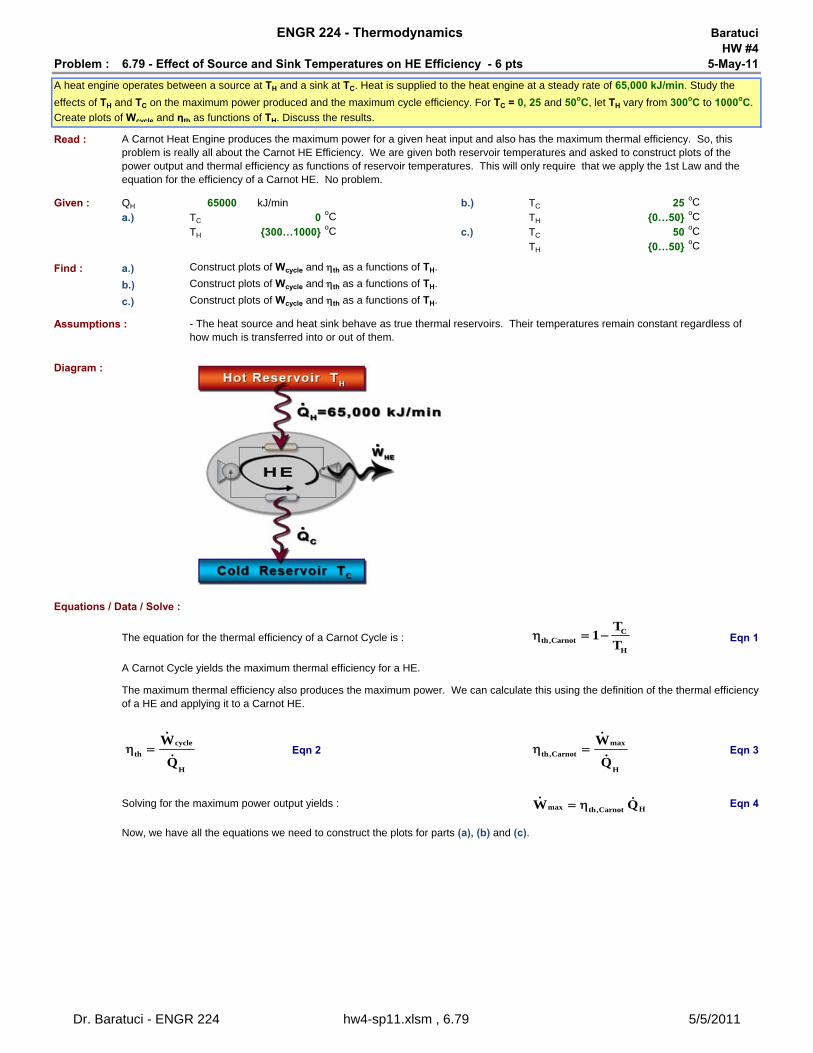
A Carnot Heat Engine produces the maximum power for a given heat input and also has the maximum thermal efficiency. So, this problem is really all about the Carnot HE Efficiency. We are given both reservoir temperatures and asked to construct plots of the power output and thermal efficiency as functions of reservoir temperatures. This will only require that we apply the 1st Law and the equation for the efficiency of a Carnot HE. No problem.
- The heat source and heat sink behave as true thermal reservoirs. Their temperatures remain constant regardless of how much is transferred into or out of them.
ENGR 224 - Thermodynamics
A heat engine operates between a source at TH and a sink at TC. Heat is supplied to the heat engine at a steady rate of 65,000 kJ/min. Study the
effects of TH and TC on the maximum power produced and the maximum cycle efficiency. For TC = 0, 25 and 50oC, let TH vary from 300oC to 1000oC.
Create plots of Wcycle and ηth as functions of TH. Discuss the results.
The maximum thermal efficiency also produces the maximum power. We can calculate this using the definition of the thermal efficiency of a HE and applying it to a Carnot HE.
Construct plots of Wcycle and th as a functions of TH.
Construct plots of Wcycle and th as a functions of TH.
Construct plots of Wcycle and th as a functions of TH.
Cth,Carnot
H
T1
T
cycle
th
H
W
Q
max
th,Carnot
H
W
Q
max Hth,CarnotW Q
Dr. Baratuci - ENGR 224 hw4-sp11.xlsm , 6.79 5/5/2011
Part a.) Part b.) Part c.)TC 0
oC TC 25oC TC 50
oC
TH (oC)
th,max
(kJ/min)Wmax
(kJ/min) TH (oC)
th,max
(kJ/min)Wmax
(kJ/min) TH (oC)
th,max
(kJ/min)Wmax
(kJ/min)
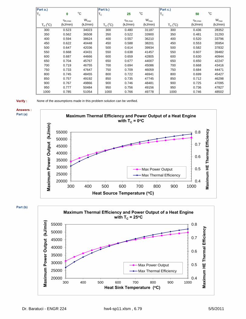
300 0.523 34023 300 0.480 31187 300 0.436 28352350 0.562 36508 350 0.522 33900 350 0.481 31293400 0.594 38624 400 0.557 36210 400 0.520 33796450 0.622 40448 450 0.588 38201 450 0.553 35954500 0.647 42036 500 0.614 39934 500 0.582 37832550 0.668 43431 550 0.638 41457 550 0.607 39482600 0.687 44666 600 0.659 42805 600 0.630 40944650 0.704 45767 650 0.677 44007 650 0.650 42247700 0.719 46755 700 0.694 45086 700 0.668 43416750 0.733 47647 750 0.709 46059 750 0.684 44471800 0.745 48455 800 0.722 46941 800 0.699 45427850 0.757 49192 850 0.735 47745 850 0.712 46298900 0.767 49866 900 0.746 48481 900 0.725 47095950 0.777 50484 950 0.756 49156 950 0.736 47827
1000 0.785 51054 1000 0.766 49778 1000 0.746 48502
Verify : None of the assumptions made in this problem solution can be verified.
Answers :Part (a)
Part (b)
0.4
0.5
0.6
0.7
0.8
20000
25000
30000
35000
40000
45000
50000
55000
300 400 500 600 700 800 900 1000 Max
imu
m H
E T
her
mal
Eff
icie
ncy
Max
imu
m P
ow
er
Ou
tpu
t (
kJ/m
in)
Heat Source Temperature (oC)
Maximum Thermal Efficiency and Power Output of a Heat Engine with TC = 0oC
Max Power Output
Max Thermal Efficiency
0.4
0.5
0.6
0.7
0.8
20000
25000
30000
35000
40000
45000
50000
55000
300 400 500 600 700 800 900 1000
Max
imu
m H
E T
her
mal
Eff
icie
ncy
Max
imu
m P
ow
er O
utp
ut
(kJ
/min
)
Heat Sink Temperature (oC)
Maximum Thermal Efficiency and Power Output of a Heat Engine with TC = 25oC
Max Power Output
Max Thermal Efficiency
Dr. Baratuci - ENGR 224 hw4-sp11.xlsm , 6.79 5/5/2011
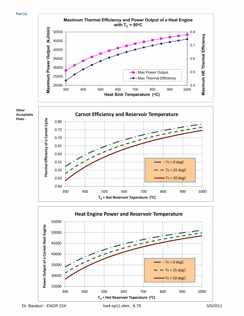
Part (c)
OtherAcceptablePlots :
0.4
0.5
0.6
0.7
0.8
20000
25000
30000
35000
40000
45000
50000
300 400 500 600 700 800 900 1000
Max
imu
m H
E T
her
mal
Eff
icie
ncy
Max
imu
m P
ow
er O
utp
ut
(kJ
/min
)
Heat Sink Temperature (oC)
Maximum Thermal Efficiency and Power Output of a Heat Engine with TC = 50oC
Max Power Output
Max Thermal Efficiency
0.40
0.45
0.50
0.55
0.60
0.65
0.70
0.75
0.80
300 400 500 600 700 800 900 1000
Therm
al Efficiency of a Carnot Cycle
TH = Hot Reservoir Teperature (oC)
Carnot Efficiency and Reservoir Temperature
Tc = 0 degC
Tc = 25 degC
Tc = 50 degC
25000
30000
35000
40000
45000
50000
55000
300 400 500 600 700 800 900 1000
Power Output of a Carnot Heat Engine
TH = Hot Reservoir Teperature (oC)
Heat Engine Power and Reservoir Temperature
Tc = 0 degC
Tc = 25 degC
Tc = 50 degC
Dr. Baratuci - ENGR 224 hw4-sp11.xlsm , 6.79 5/5/2011
BaratuciHW #4
Problem : 6.85 - Thermal Efficiency of a Geothermal Power Plant - 3 pts 5-May-11
a.)
b.)
c.) The actual rate of heat rejection from this power plant.
Read :
Given : mgeo 210 kg/s Ws 8000 kW
Tgeo,in 150oC Tgeo,out 90
oC
423.15 K Tsurr 25oC
298.15 K
Find : a.) ??? %b.) max ??? % c.) QC ??? kW
Assumptions :1 - All of the heat given up by the geothermal water is taken in by the heat engine.2 - Changes in kinetic and potential energy of the geothermal water are negligible.3 - The geothermal water is an incompressible liquid over the range of pressure from its inlet to its outlet condition.4 -
Diagram :
Solution :
Part a.)
Eqn 1
Eqn 2
Eqn 3
We can simplify Eqn 2 if we assume that changes in kinetic and potential energies are negligible and that any shaft work produced or consumed are taken into account in the WS value given in the problem statement.
ENGR 224 - Thermodynamics
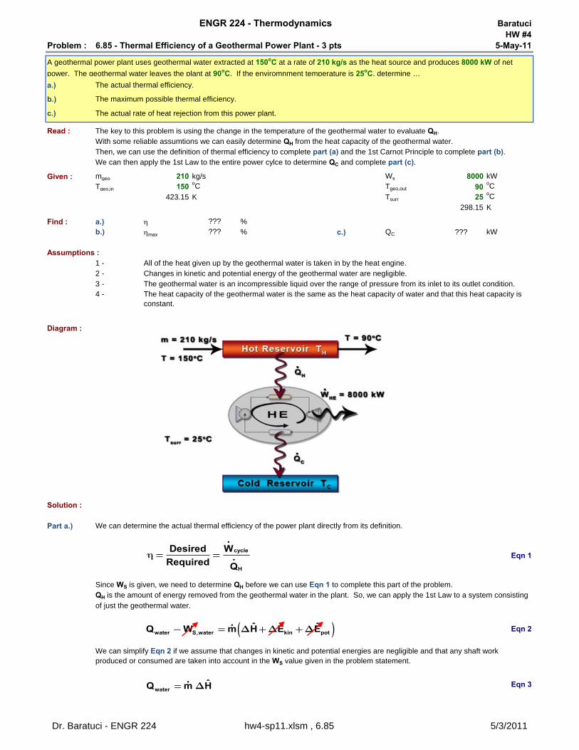
A geothermal power plant uses geothermal water extracted at 150oC at a rate of 210 kg/s as the heat source and produces 8000 kW of net
power. The geothermal water leaves the plant at 90oC. If the enviromnment temperature is 25oC, determine …
The actual thermal efficiency.
The maximum possible thermal efficiency.
We can determine the actual thermal efficiency of the power plant directly from its definition.
The heat capacity of the geothermal water is the same as the heat capacity of water and that this heat capacity is constant.
The key to this problem is using the change in the temperature of the geothermal water to evaluate QH.With some reliable assumtions we can easily determine QH from the heat capacity of the geothermal water.
We can then apply the 1st Law to the entire power cylce to determine QC and complete part (c).Then, we can use the definition of thermal efficiency to complete part (a) and the 1st Carnot Principle to complete part (b).
Since WS is given, we need to determine QH before we can use Eqn 1 to complete this part of the problem.QH is the amount of energy removed from the geothermal water in the plant. So, we can apply the 1st Law to a system consisting of just the geothermal water.
cycle
H
Desired W
Required Qh = =
waterˆQ m H= D
( )water S,water kin potˆ ˆ ˆQ W m H E E- = D +D +D
Dr. Baratuci - ENGR 224 hw4-sp11.xlsm , 6.85 5/3/2011
Eqn 4
Eqn 5
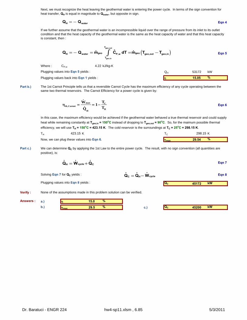
Where : CP,w 4.22 kJ/kg-K
Plugging values into Eqn 5 yields : QH 53172 kW
Plugging values back into Eqn 1 yields : 15.05 %
Part b.)
Eqn 6
TH 423.15 K TC 298.15 K
Now, we can plug these values into Eqn 6. max 29.54 %
Part c.)
Eqn 7
Solving Eqn 7 for QC yields : Eqn 8
Plugging values into Eqn 8 yields : QC 45172 kW
Verify : None of the assumptions made in this problem solution can be verified.
Answers : a.) 15.0 %
b.) max 29.5 % c.) QC 45200 kW
Next, we must recognize the heat leaving the geothermal water is entering the power cycle. In terms of the sign convention for heat transfer, QH is equal in magnitude to Qwater, but opposite in sign.
We can determine QC by applying the 1st Law to the entire power cycle. The result, with no sign convention (all quantities are positive), is:
The 1st Carnot Principle tells us that a reversible Carnot Cycle has the maximum efficiency of any cycle operating between the same two thermal reservoirs. The Carnot Efficiency for a power cycle is given by:
In this case, the maximum efficiency would be achieved if the geothermal water behaved a true thermal reservoir and could supply
heat while remaining constantly at Tgeo,in = 150oC instead of dropping to Tgeo,out = 90oC. So, for the maimum possible thermal
efficiency, we will use TH = 150oC = 423.15 K. The cold reservoir is the surroundings at TC = 25oC = 298.15 K.
If we further assume that the geothermal water is an incompressible liquid over the range of pressure from its inlet to its outlet condition and that the heat capacity of the geothermal water is the same as the heat capacity of water and that this heat capacity is constant, then :
H waterQ Q=-
( )geo,out
geo,in
T
geo geoH water P,w geo,out geo,in
T
ˆQ Q m C dT m T T=- = = -ò
max Cth,Carnot
HH
TW1
TQ
cycleH CQ W Q= +
cycleC HQ Q W= -
Dr. Baratuci - ENGR 224 hw4-sp11.xlsm , 6.85 5/3/2011
BaratuciHW #4
Problem : 6.107 - Carnot HE Used to Drive a Carnot Refrigerator - 6 pts 5-May-11
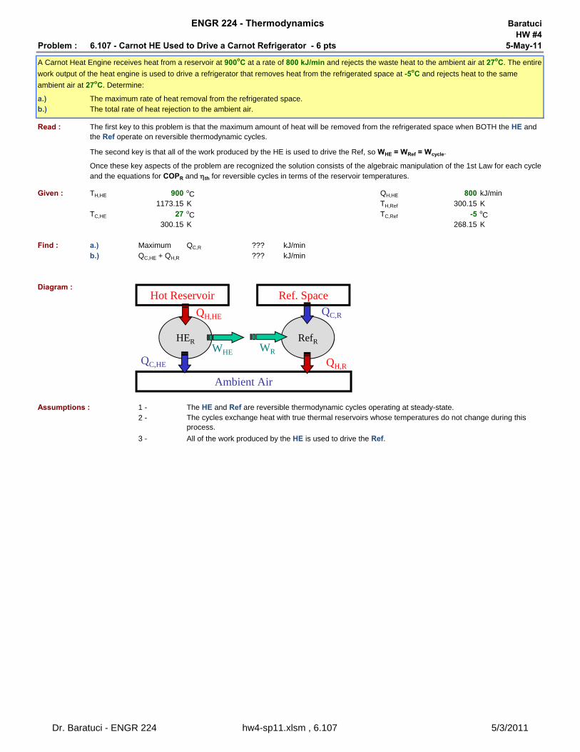
a.) The maximum rate of heat removal from the refrigerated space.b.) The total rate of heat rejection to the ambient air.
Read :
Given : TH,HE 900 oC QH,HE 800 kJ/min1173.15 K TH,Ref 300.15 K
TC,HE 27 oC TC,Ref -5 oC300.15 K 268.15 K
Find : a.) Maximum QC,R ??? kJ/minb.) QC,HE + QH,R ??? kJ/min
Diagram :
Assumptions : 1 - The HE and Ref are reversible thermodynamic cycles operating at steady-state.2 -
3 - All of the work produced by the HE is used to drive the Ref.
ENGR 224 - Thermodynamics
The second key is that all of the work produced by the HE is used to drive the Ref, so WHE = WRef = Wcycle.
A Carnot Heat Engine receives heat from a reservoir at 900oC at a rate of 800 kJ/min and rejects the waste heat to the ambient air at 27oC. The entire
work output of the heat engine is used to drive a refrigerator that removes heat from the refrigerated space at -5oC and rejects heat to the same
ambient air at 27oC. Determine:
The cycles exchange heat with true thermal reservoirs whose temperatures do not change during this process.
The first key to this problem is that the maximum amount of heat will be removed from the refrigerated space when BOTH the HE and the Ref operate on reversible thermodynamic cycles.
Once these key aspects of the problem are recognized the solution consists of the algebraic manipulation of the 1st Law for each cycle and the equations for COPR and th for reversible cycles in terms of the reservoir temperatures.
RefRHER
Ambient Air
QC,HE
WHE
Hot Reservoir
WR
QH,HE
QH,R
QC,R
Ref. Space
Dr. Baratuci - ENGR 224 hw4-sp11.xlsm , 6.107 5/3/2011
Equations / Data / Solve :
Part a.)
We can determine QC,R from the COPR : Eqn 1
Solving for QC,R gives us : Eqn 2
So, we need to evaluate COPR and WR so we can use Eqn 2 to evaluate QC,R.
Eqn 3
Eqn 4 Eqn 5
Plugging in values gives us : th,rev 0.7442COPR,rev 8.380
Next, we can solve Eqn 4 for Wcycle :Eqn 6
Wcycle 595.3 kJ/min
Finally, we can plug values back into Eqn 2 (where WR = Wcycle). QC,R 4989 kJ/min
Part b.) We can solve this part of the problem by applying the 1st Law to each cycle.
Eqn 7 Eqn 8
Solve Eqn 8 for QC,HE : Eqn 9
Now, we can plug values into Eqns 7 & 9 : QH,R 5583.9 kJ/minQC,HE 204.7 kJ/minQC,HE + QH,R 5788.6 kJ/min
Verify : None of the assumptions made in this problem solution can be verified.
Answers : a.) QC,R 4989 kJ/min
b.) QC,HE + QH,R 5789 kJ/min
We can use the thermal efficiency of the HE to determine Wcycle. Since we know the temperature of all four thermal reservoirs, we can
determine the thermal efficiency of the HE and the COPR.
The maximum value of QC,R will be achieved when BOTH the HE and the Ref operate on reversible cycles. So, we assume that both cycles are reversible.
Because all of the work produced by the HE is used to drive the refrigerator :
R,revH
C
1COP
T1
T
cycleCth,rev
H H,HE
WT1
T Q
C,RR
R
QCOP
W
C,R R RQ W COP
R HE cycleW W W
cycle th,rev H,HEW Q
H,R C,R cycleQ Q W
C,HE H,HE cycleQ Q W
H,HE C,HE cycleQ Q W
Dr. Baratuci - ENGR 224 hw4-sp11.xlsm , 6.107 5/3/2011
BaratuciHW #4
Problem : 6.110 - Actual and Maximum COP of an Air-Conditioner - 8 pts 5-May-11
a.) The actual COP
b.) The maximum COP
c.)
Read :
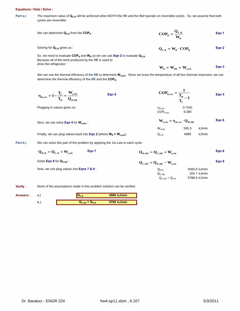
Given : Chemical : R-134a P1 400 kPaUnits : SI_C x1 1 kg vap/kgTroom 23 oC V1 100 L/min
296.15 0.001667 m3/sToutside 37 oC
310.15 P2 1200 kPaQwalls 250 kJ/min T2 70 oC
4167 WQelec 900 W
Find : a.) COP ???b.) COPmax ???
c.) V1,min ??? m3/s
Diagram :
Assumptions : 1 -2 -
3 -
4 -
The compressor is adiabatic.
Changes in kinetic and potential energies are negligible in the compressor.
The compressor is the only process in the air-conditioner cycle that produces or consumes work or power.
ENGR 224 - Thermodynamics
An air-conditioner with R-134a as the working fluid is used to keep a room at 23oC by rejecting the waste heat to the outside air at 37oC. The room gains heat through the walls and the windows at a rate of 250 kJ/min while the heat generated by the computer, TV, and lights amounts to
900 W. The refrigerant enters the compressor at 400 kPa as a saturated vapor at a rate of 100 L/min and leaves at 1200 kPa and 70oC. Deterine...
The minimum volumetric flow rate of the R-134a at the compressor inlet for the same compressor inlet and exit conditions.
The air-conditioner operates at steady-state.
It s important to recognize that when the room temperature is steady, QC must be equal to the rate at which heat flows into the
room from all sources. In this case, QC must be equal to the sum of the rate at which heat flows into the room from the hot outdoor air and the rate at which electrical appliances dissipate energy in the form of heat inside the room.
Part (a) is an application of the 1st Law and the definition of COP for a refrigeration cycle.Part (b) is an application of the definition of COP for a refrigeration cycle and the Kelvin Principle.Part (c) is an application of the 1st Law to the reversible refrigeration cycle from part (b). The key is to recognize that a reversible refrigeration cycle requires the minimum work to accomplish a given refrigeration process.
P1 = 400 kPax1 = 1.0 kg vap/kgV1 = 100 L/min
P2 = 1200 kPaT2 = 70
oC
Compressor
Dr. Baratuci - ENGR 224 hw4-sp11.xlsm , 6.110 5/3/2011
Equations / Data / Solve : CompressorInlet
1
CompressorOutlet
2
T 8.9 70 oCP 400 1200 kPaTsat 8.9 46.3 oCx 1 N/A kg vap/kg
H 403.72 448.76 kJ/kg
V 0.051207 0.019502 m3/kg
PhaseSaturated
VaporSuperheated
Vapor
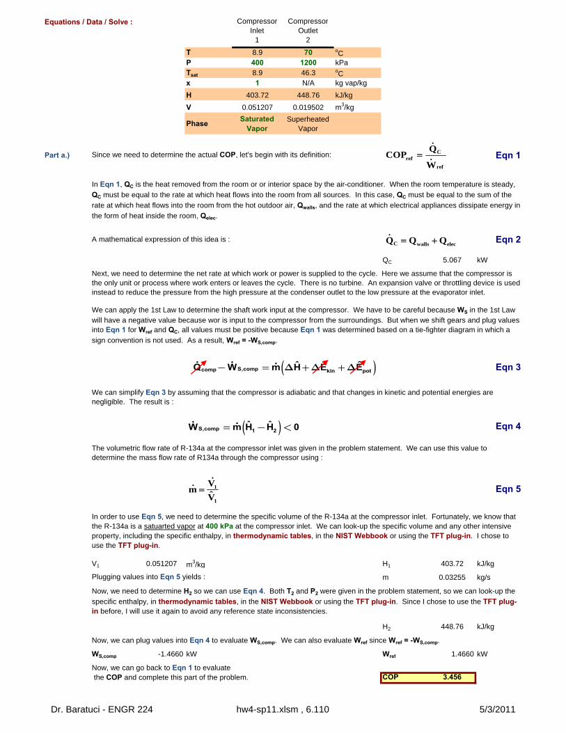
Part a.) Eqn 1
A mathematical expression of this idea is : Eqn 2
QC 5.067 kW
Eqn 3
Eqn 4
Eqn 5
V1 0.051207 m3/kg H1 403.72 kJ/kg
Plugging values into Eqn 5 yields : m 0.03255 kg/s
H2 448.76 kJ/kg
WS,comp -1.4660 kW Wref 1.4660 kW
COP 3.456
Now, we need to determine H2 so we can use Eqn 4. Both T2 and P2 were given in the problem statement, so we can look-up the
specific enthalpy, in thermodynamic tables, in the NIST Webbook or using the TFT plug-in. Since I chose to use the TFT plug-in before, I will use it again to avoid any reference state inconsistencies.
Now, we can plug values into Eqn 4 to evaluate WS,comp. We can also evaluate Wref since Wref = -WS,comp.
Now, we can go back to Eqn 1 to evaluate the COP and complete this part of the problem.
We can simplify Eqn 3 by assuming that the compressor is adiabatic and that changes in kinetic and potential energies are negligible. The result is :
The volumetric flow rate of R-134a at the compressor inlet was given in the problem statement. We can use this value to determine the mass flow rate of R134a through the compressor using :
In order to use Eqn 5, we need to determine the specific volume of the R-134a at the compressor inlet. Fortunately, we know that the R-134a is a satuarted vapor at 400 kPa at the compressor inlet. We can look-up the specific volume and any other intensive property, including the specific enthalpy, in thermodynamic tables, in the NIST Webbook or using the TFT plug-in. I chose to use the TFT plug-in.
In Eqn 1, QC is the heat removed from the room or or interior space by the air-conditioner. When the room temperature is steady,
QC must be equal to the rate at which heat flows into the room from all sources. In this case, QC must be equal to the sum of the
rate at which heat flows into the room from the hot outdoor air, Qwalls, and the rate at which electrical appliances dissipate energy in
the form of heat inside the room, Qelec.
Next, we need to determine the net rate at which work or power is supplied to the cycle. Here we assume that the compressor is the only unit or process where work enters or leaves the cycle. There is no turbine. An expansion valve or throttling device is used instead to reduce the pressure from the high pressure at the condenser outlet to the low pressure at the evaporator inlet.
We can apply the 1st Law to determine the shaft work input at the compressor. We have to be careful because WS in the 1st Law will have a negative value because wor is input to the compressor from the surroundings. But when we shift gears and plug values into Eqn 1 for Wref and QC, all values must be positive because Eqn 1 was determined based on a tie-fighter diagram in which a
sign convention is not used. As a result, Wref = -WS,comp.
Since we need to determine the actual COP, let's begin with its definition: Cref
ref
QCOP
W
C walls elecQ Q Q
( )S,compcomp kin potˆ ˆ ˆQ W m H E E- = D +D +D
( )S,comp 1 2ˆ ˆW m H H 0= - <
1
1
Vm
V̂
Dr. Baratuci - ENGR 224 hw4-sp11.xlsm , 6.110 5/3/2011
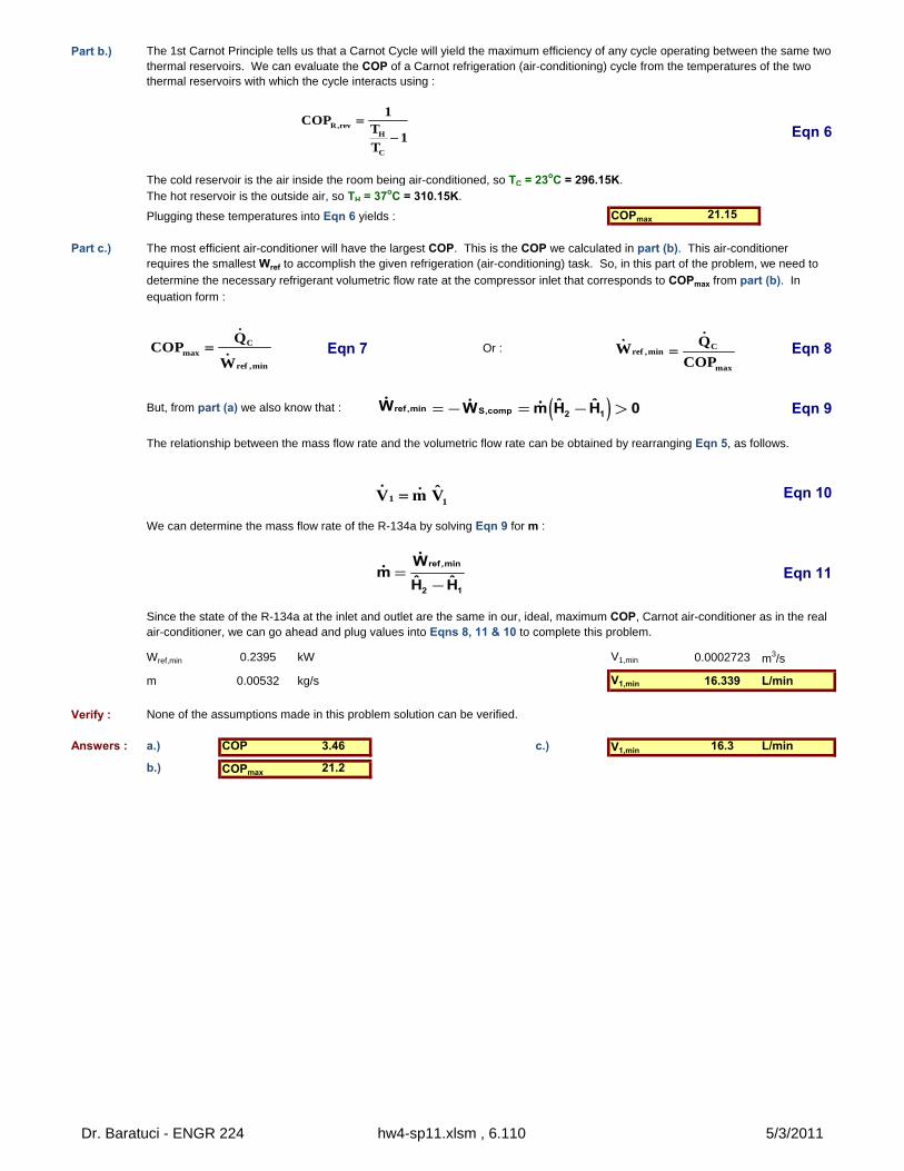
Part b.)
Eqn 6
Plugging these temperatures into Eqn 6 yields : COPmax 21.15
Part c.)
Eqn 7 Or : Eqn 8
Eqn 9
Eqn 10
Eqn 11
Wref,min 0.2395 kW V1,min 0.0002723 m3/s
m 0.00532 kg/s V1,min 16.339 L/min
Verify : None of the assumptions made in this problem solution can be verified.
Answers : a.) COP 3.46 c.) V1,min 16.3 L/min
b.) COPmax 21.2
Since the state of the R-134a at the inlet and outlet are the same in our, ideal, maximum COP, Carnot air-conditioner as in the real air-conditioner, we can go ahead and plug values into Eqns 8, 11 & 10 to complete this problem.
But, from part (a) we also know that :
We can determine the mass flow rate of the R-134a by solving Eqn 9 for m :
The relationship between the mass flow rate and the volumetric flow rate can be obtained by rearranging Eqn 5, as follows.
The cold reservoir is the air inside the room being air-conditioned, so TC = 23oC = 296.15K.The hot reservoir is the outside air, so TH = 37oC = 310.15K.
The most efficient air-conditioner will have the largest COP. This is the COP we calculated in part (b). This air-conditioner requires the smallest Wref to accomplish the given refrigeration (air-conditioning) task. So, in this part of the problem, we need to
determine the necessary refrigerant volumetric flow rate at the compressor inlet that corresponds to COPmax from part (b). In equation form :
The 1st Carnot Principle tells us that a Carnot Cycle will yield the maximum efficiency of any cycle operating between the same two thermal reservoirs. We can evaluate the COP of a Carnot refrigeration (air-conditioning) cycle from the temperatures of the two thermal reservoirs with which the cycle interacts using :
R,revH
C
1COP
T1
T
Cmax
ref ,min
QCOP
W
C
ref ,min
max
QWCOP
( )ref ,min S,comp 2 1ˆ ˆW W m H H 0=- = - >
1 1ˆV m V
ref ,min
2 1
Wm
ˆ ˆH H=
-
Dr. Baratuci - ENGR 224 hw4-sp11.xlsm , 6.110 5/3/2011
BaratuciHW #4
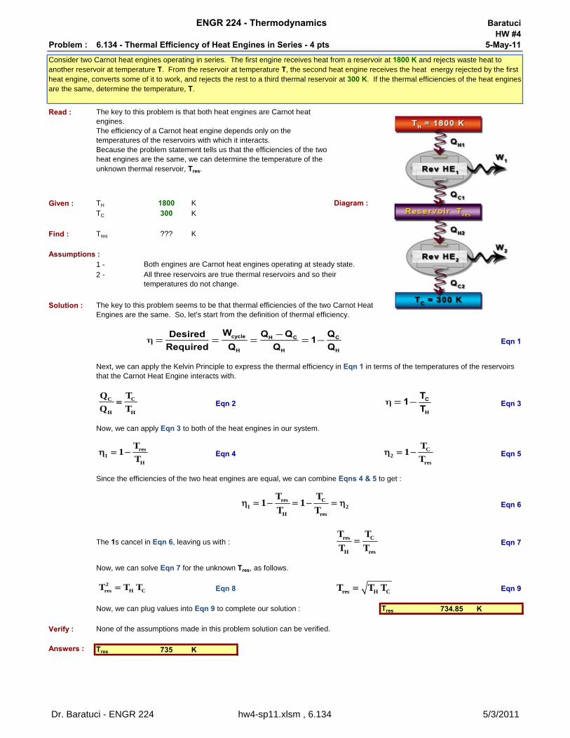
Problem : 6.134 - Thermal Efficiency of Heat Engines in Series - 4 pts 5-May-11
Read :
Given : TH 1800 K Diagram :TC 300 K
Find : Tres ??? K
Assumptions :1 -2 -
Solution :
Eqn 1
Eqn 2 Eqn 3
Eqn 4 Eqn 5
Eqn 6
Eqn 7
Eqn 8 Eqn 9
Tres 734.85 K
Verify : None of the assumptions made in this problem solution can be verified.
Answers : Tres 735 K
ENGR 224 - Thermodynamics
Consider two Carnot heat engines operating in series. The first engine receives heat from a reservoir at 1800 K and rejects waste heat to another reservoir at temperature T. From the reservoir at temperature T, the second heat engine receives the heat energy rejected by the first heat engine, converts some of it to work, and rejects the rest to a third thermal reservoir at 300 K. If the thermal efficiencies of the heat engines are the same, determine the temperature, T.
The key to this problem is that both heat engines are Carnot heat engines.The efficiency of a Carnot heat engine depends only on the temperatures of the reservoirs with which it interacts.Because the problem statement tells us that the efficiencies of the two heat engines are the same, we can determine the temperature of the unknown thermal reservoir, Tres.
Both engines are Carnot heat engines operating at steady state.All three reservoirs are true thermal reservoirs and so their temperatures do not change.
The key to this problem seems to be that thermal efficiencies of the two Carnot Heat Engines are the same. So, let's start from the definition of thermal efficiency.
Now, we can plug values into Eqn 9 to complete our solution :
Next, we can apply the Kelvin Principle to express the thermal efficiency in Eqn 1 in terms of the temperatures of the reservoirs that the Carnot Heat Engine interacts with.
Now, we can apply Eqn 3 to both of the heat engines in our system.
Since the efficiencies of the two heat engines are equal, we can combine Eqns 4 & 5 to get :
The 1s cancel in Eqn 6, leaving us with :
Now, we can solve Eqn 7 for the unknown Tres, as follows.
res1
H
T1
T C
2res
T1
T
res C1 2
H res
T T1 1
T T
res C
H res
T T
T T
2res H CT T T
res H CT T T
cycle H C C
H H H
W Q Q QDesired1
Required Q Q Q
-h = = = = -
C C
H H
Q T
Q T C
H
T1
Th = -
Dr. Baratuci - ENGR 224 hw4-sp11.xlsm , 6.134 5/3/2011
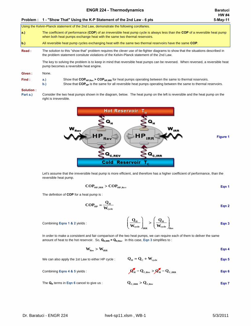
BaratuciHW #4
Problem : 1 - "Show That" Using the K-P Statement of the 2nd Law - 6 pts 5-May-11
a.)
b.)
Read :
Given : None.
Find : a.) Show that COPHP,Rev > COPHP,IRR for heat pumps operating between the same to thermal reservoirs.b.) Show that COPHP is the same for all reversible heat pumps operating between the same to thermal reservoirs.
Solution :Part a.)
Figure 1
Eqn 1
Eqn 2
Eqn 3
Eqn 4
We can also apply the 1st Law to either HP cycle : Eqn 5
Combining Eqns 4 & 5 yields : Eqn 6
Eqn 7
ENGR 224 - Thermodynamics
Using the Kelvin-Planck statement of the 2nd Law, demonstrate the following corollaries.
The coefficient of performance (COP) of an irreversible heat pump cycle is always less than the COP of a reversible heat pump when both heat pumps exchange heat with the same two thermal reservoirs.
All reversible heat pump cycles exchanging heat with the same two thermal reservoirs have the same COP.
Combining Eqns 1 & 2 yields :
In order to make a consistent and fair comparison of the two heat pumps, we can require each of them to deliver the same amount of heat to the hot reservoir. So, QH,IRR = QH,Rev. In this case, Eqn 3 simplifies to :
Consider the two heat pumps shown in the diagram, below. The heat pump on the left is reversible and the heat pump on the right is irreversible.
Let's assume that the irreversible heat pump is more efficient, and therefore has a higher coefficient of performance, than the reversible heat pump.
The definition of COP for a heat pump is :
The QH terms in Eqn 6 cancel to give us :
The solution to this "show that" problem requires the clever use of tie-fighter diagrams to show that the situations described in the problem statement consitute violations of the Kelvin-Planck statement of the 2nd Law.
The key to solving the problem is to keep in mind that reversible heat pumps can be reversed. When reversed, a reversible heat pump becomes a reversible heat engine.
HP,IRR HP,Re vCOP COP
HHP
cycle
QCOP
W
H H
cycle cycleIRR Rev
Q Q
W W
Rev IRRW W
H C cycleQ Q W
H C,Rev H C,IRRQ Q Q Q
C,IRR C,RevQ Q
Dr. Baratuci - ENGR 224 hw4-sp11.xlsm , WB-1 5/3/2011
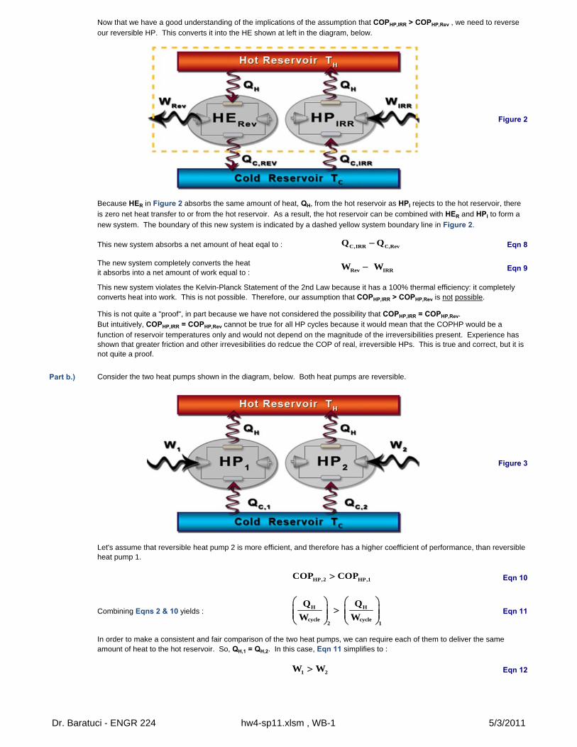
Figure 2
This new system absorbs a net amount of heat eqal to : Eqn 8
Part b.)
Figure 3
Eqn 10
Combining Eqns 2 & 10 yields : Eqn 11
Eqn 12
Now that we have a good understanding of the implications of the assumption that COPHP,IRR > COPHP,Rev , we need to reverse our reversible HP. This converts it into the HE shown at left in the diagram, below.
Because HER in Figure 2 absorbs the same amount of heat, QH, from the hot reservoir as HPI rejects to the hot reservoir, there
is zero net heat transfer to or from the hot reservoir. As a result, the hot reservoir can be combined with HER and HPI to form a
new system. The boundary of this new system is indicated by a dashed yellow system boundary line in Figure 2.
The new system completely converts the heatit absorbs into a net amount of work equal to :
Eqn 9
In order to make a consistent and fair comparison of the two heat pumps, we can require each of them to deliver the same amount of heat to the hot reservoir. So, QH,1 = QH,2. In this case, Eqn 11 simplifies to :
This new system violates the Kelvin-Planck Statement of the 2nd Law because it has a 100% thermal efficiency: it completely converts heat into work. This is not possible. Therefore, our assumption that COPHP,IRR > COPHP,Rev is not possible.
This is not quite a "proof", in part because we have not considered the possibility that COPHP,IRR = COPHP,Rev.But intuitively, COPHP,IRR = COPHP,Rev cannot be true for all HP cycles because it would mean that the COPHP would be a function of reservoir temperatures only and would not depend on the magnitude of the irreversibilities present. Experience has shown that greater friction and other irrevesibilities do redcue the COP of real, irreversible HPs. This is true and correct, but it is not quite a proof.
Consider the two heat pumps shown in the diagram, below. Both heat pumps are reversible.
Let's assume that reversible heat pump 2 is more efficient, and therefore has a higher coefficient of performance, than reversible heat pump 1.
C,IRR C,RevQ Q
Rev IRRW W
HP,2 HP,1COP COP
H H
cycle cycle2 1
Q Q
W W
1 2W W
Dr. Baratuci - ENGR 224 hw4-sp11.xlsm , WB-1 5/3/2011
We can now use the 1st Law as applied to a HP cycle, shown in Eqn 5, to express Eqn 12 in terms of heat only.
Eqn 13
Eqn 14
Figure 4
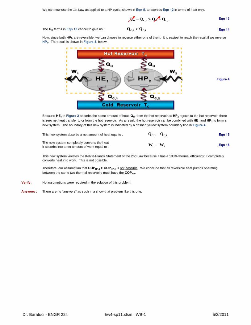
This new system absorbs a net amount of heat eqal to : Eqn 15
Verify : No assumptions were required in the solution of this problem.
Answers : There are no "answers" as such in a show-that problem like this one.
Because HE1 in Figure 2 absorbs the same amount of heat, QH, from the hot reservoir as HP2 rejects to the hot reservoir, there
is zero net heat transfer to or from the hot reservoir. As a result, the hot reservoir can be combined with HE1 and HP2 to form a
new system. The boundary of this new system is indicated by a dashed yellow system boundary line in Figure 4.
This new system violates the Kelvin-Planck Statement of the 2nd Law because it has a 100% thermal efficiency: it completely converts heat into work. This is not possible.
Therefore, our assumption that COPHP,2 > COPHP,1 is not possible. We conclude that all reversible heat pumps operating
between the same two thermal reservoirs must have the COPHP.
The new system completely converts the heatit absorbs into a net amount of work equal to :
Eqn 16
The QH terms in Eqn 13 cancel to give us :
Now, since both HPs are reversible, we can choose to reverse either one of them. It is easiest to reach the result if we reverse HP1. The result is shown in Figure 4, below.
H C,1 H C,2Q Q Q Q
C,2 C,1Q Q
C,2 C,1Q Q
1 2W W
Dr. Baratuci - ENGR 224 hw4-sp11.xlsm , WB-1 5/3/2011
BaratuciHW #4
Problem : WB-2 - Rev., Irrev. and Impossible Refrigeration Cycles - 6 pts 5-May-11
a.) QC = 1000 kJ and Wcycle = 400 kJ c.) QH = 1500 kJ and Wcycle = 200 kJb.) QC = 1500 kJ and QH = 1800 kJ d.) COP = 4
Read : The key is to apply the 1st and 2nd Carnot Principles to reversible refrigeration cycles.
Given : TC 250 K b.) QC 1500 kJTH 300 K QH 1800 kJ
a.) QC 1000 kJ c.) QH 1500 kJWcycle 400 kJ Wcycle 200 kJ
d.) COPR 4
Find : Reversible ?Irreversible ?Impossible ?
Diagram :
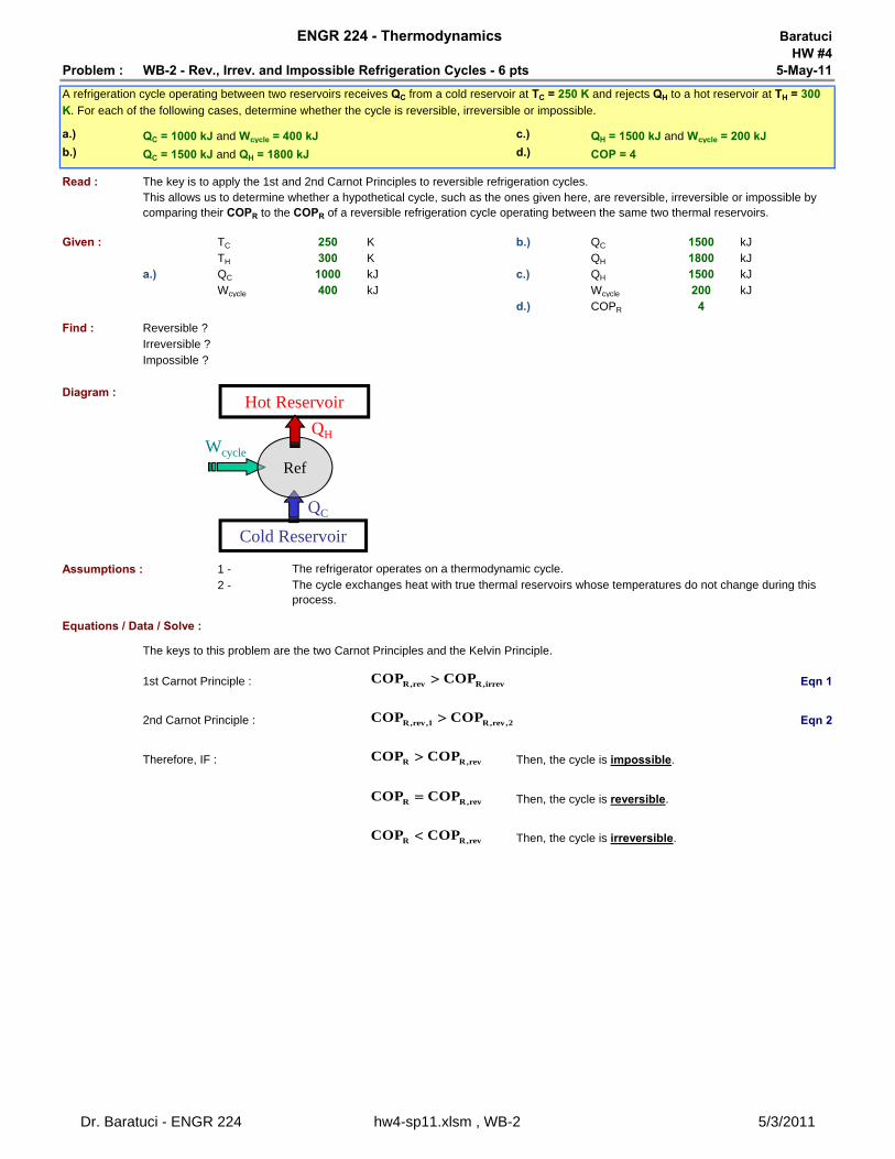
Assumptions : 1 - The refrigerator operates on a thermodynamic cycle.
2 -
Equations / Data / Solve :
The keys to this problem are the two Carnot Principles and the Kelvin Principle.
1st Carnot Principle : Eqn 1
2nd Carnot Principle : Eqn 2
Therefore, IF : Then, the cycle is impossible.
Then, the cycle is reversible.
Then, the cycle is irreversible.
This allows us to determine whether a hypothetical cycle, such as the ones given here, are reversible, irreversible or impossible by comparing their COPR to the COPR of a reversible refrigeration cycle operating between the same two thermal reservoirs.
ENGR 224 - Thermodynamics
A refrigeration cycle operating between two reservoirs receives QC from a cold reservoir at TC = 250 K and rejects QH to a hot reservoir at TH = 300
K. For each of the following cases, determine whether the cycle is reversible, irreversible or impossible.
The cycle exchanges heat with true thermal reservoirs whose temperatures do not change during this process.
Cold Reservoir
QC
Wcycle
Ref
Hot Reservoir
QH
R,rev R,irrevCOP COP
R,rev,1 R,rev,2COP COP
R R,revCOP COP
R R,revCOP COP
R R,revCOP COP
Dr. Baratuci - ENGR 224 hw4-sp11.xlsm , WB-2 5/3/2011
Let's begin with the definition of COPR : Eqn 3
We can then apply the 1st Law to the cycle : Eqn 4
Now, use Eqn 4 to eliminate Wcycle from Eqn 3 : Eqn 5
Eqn 6
Combining Eqns 5 & 6 gives us : Eqn 7
We can put numbers into Eqn 7 : COPR,rev 5
Now, we can calculate the COPR values for the three refrigerators in parts (a) - (c).
Part a.) Use Eqn 2 to evaluate COPR : COPR,A 2.5
Since : we can conclude that this refrigeration cycle is irreversible.
Part b.) Use Eqn 4 to evaluate COPR : COPR,B 5
Since : we can conclude that this refrigeration cycle is reversible.
Part c.) Solve Eqn 2 for QC : Eqn 7
Plugging values into Eqn 7 and then Eqn 4 gives us : QC 1300 kJCOPR,C 6.5
Since : we can conclude that this refrigeration cycle is impossible.
Part d.) Since : we can conclude that this refrigeration cycle is irreversible.
Verify : None of the assumptions made in this problem solution can be verified.
Answers : a.) c.)
b.) d.)
Now, the Kelvin Principle tells us that, for a reversible cycle like the Carnot Cycle, :
So, the key is to determine the COPR of the actual refrigerator and compare it to the COPR of a reversible refrigerator operating between the same two thermal reservoirs.
Reversible
Irreversible Impossible
Irreversible
CR
cycle
QCOP
W
C cycle HQ W Q
CR
HH C
C
Q 1COP
QQ Q1
Q
H H
C C
Q T
Q T
R,revH
C
1COP
T1
T
R,A R,revCOP COP
R,B R,revCOP COP
R,C R,revCOP COP
C H cycleQ Q W
R,D R,revCOP COP
Dr. Baratuci - ENGR 224 hw4-sp11.xlsm , WB-2 5/3/2011
BaratuciHW #4
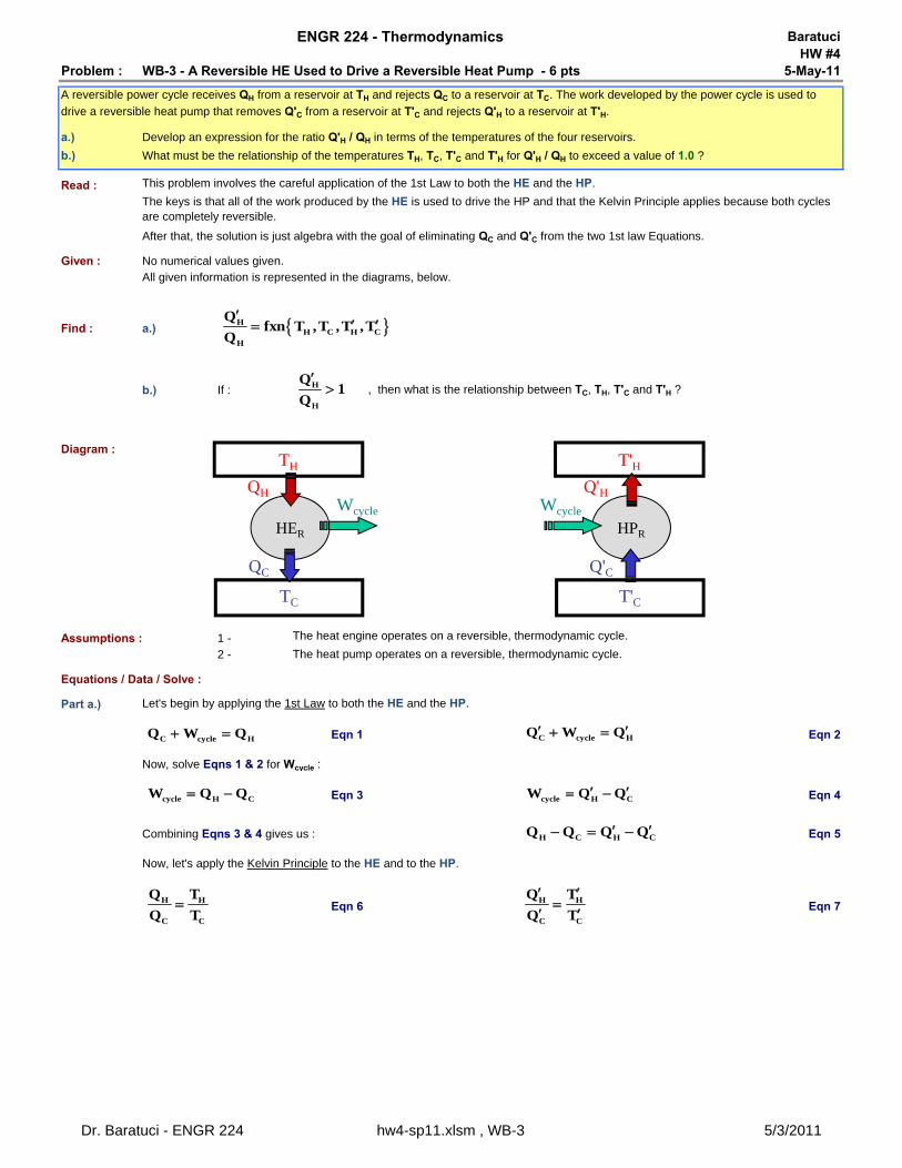
Problem : WB-3 - A Reversible HE Used to Drive a Reversible Heat Pump - 6 pts 5-May-11
a.)
b.)
Read :
Given : No numerical values given.All given information is represented in the diagrams, below.
Find : a.)
b.) If : , then what is the relationship between TC, TH, T'C and T'H ?
Diagram :
Assumptions : 1 - The heat engine operates on a reversible, thermodynamic cycle.
2 - The heat pump operates on a reversible, thermodynamic cycle.
Equations / Data / Solve :
Part a.) Let's begin by applying the 1st Law to both the HE and the HP.
Eqn 1 Eqn 2
Now, solve Eqns 1 & 2 for Wcycle :
Eqn 3 Eqn 4
Combining Eqns 3 & 4 gives us : Eqn 5
Eqn 6 Eqn 7
Now, let's apply the Kelvin Principle to the HE and to the HP.
After that, the solution is just algebra with the goal of eliminating QC and Q'C from the two 1st law Equations.
ENGR 224 - Thermodynamics
A reversible power cycle receives QH from a reservoir at TH and rejects QC to a reservoir at TC. The work developed by the power cycle is used to
drive a reversible heat pump that removes Q'C from a reservoir at T'C and rejects Q'H to a reservoir at T'H.
Develop an expression for the ratio Q'H / QH in terms of the temperatures of the four reservoirs.
What must be the relationship of the temperatures TH, TC, T'C and T'H for Q'H / QH to exceed a value of 1.0 ?
This problem involves the careful application of the 1st Law to both the HE and the HP.
The keys is that all of the work produced by the HE is used to drive the HP and that the Kelvin Principle applies because both cycles are completely reversible.
HER
TC
QC
Wcycle
TH
QH
HPR
T'C
Q'C
Wcycle
T'HQ'H
HH C H C
H
Qfxn T ,T ,T ,T
Q
H
H
Q1
Q
C cycle HQ W Q C cycle HQ W Q
cycle H CW Q Q cycle H CW Q Q
H C H CQ Q Q Q
H H
C C
Q T
Q T H H
C C
Q T
Q T
Dr. Baratuci - ENGR 224 hw4-sp11.xlsm , WB-3 5/3/2011
Now, we can use Eqns 6 & 7 to eliminate QC and Q'C from Eqn 5, as follows.
Eqn 8 Eqn 9
Plugging Eqns 8 & 9 into Eqn 5 gives us: Eqn 10
Or, after factoring QH and Q'H : Eqn 11
Now, solve Eqn 11 for QH / Q'H : Eqn 12
Or, clearing some of the fractions : Eqn 13
Part b.) When : Eqn 12 becomes : Eqn 14
In Eqn 14, the 1's cancel, leaving us with : Eqn 15
Recall that when you multiply an inequality by (-1) "greater than" becomes "less than".
So, Eqn 15 becomes : Eqn 16
Or : Eqn 17
Verify : None of the assumptions made in this problem solution can be verified.
Answers : a.) b.)
CC H
H
TQ Q
T C
C HH
TQ Q
T
C CH H H H
H H
T TQ Q Q Q
T T
C CH H
H H
T TQ 1 Q 1
T T
C
H H
CH
H
T1
Q TTQ
1T
H H CH
H H H C
T T TQ
Q T T T
H
H
Q1
Q
C C
H H
T T1 1
T T
C C
H H
T T
T T
C C
H H
T T
T T
C H
C H
T T
T T
H H CH
H H H C
T T TQ
Q T T T
C H
C H
T T
T T
Dr. Baratuci - ENGR 224 hw4-sp11.xlsm , WB-3 5/3/2011
![Science...6.72 [Topic 2] Respiration, Circulation & Excretion 6.74 Previous Years’ Examination Questions Topic 2 6.75 Solutions 6.78 Multiple Choice Questions 6.79 Solutions 6.79](https://static.fdocuments.in/doc/165x107/6117a0010652115e6022d1ac/science-672-topic-2-respiration-circulation-excretion-674-previous.jpg)


![Engines and Carnot Cycle Markscheme - We Love …...1 Engines and Carnot Cycle Markscheme 1a. [1 mark] The P–V diagram of the Carnot cycle for a monatomic ideal gas is shown. State](https://static.fdocuments.in/doc/165x107/5fdebb59ad4070290d497d2d/engines-and-carnot-cycle-markscheme-we-love-1-engines-and-carnot-cycle-markscheme.jpg)

