ENGR 111 9.2 Sectioned Views Thursday, October 28 th 2004.
31
ENGR 111 9.2 Sectioned Views Thursday, October 28 th 2004
-
Upload
charlotte-ly -
Category
Documents
-
view
215 -
download
1
Transcript of ENGR 111 9.2 Sectioned Views Thursday, October 28 th 2004.
ENGR 111 9.2
Sectioned Views
Thursday, October 28th 2004
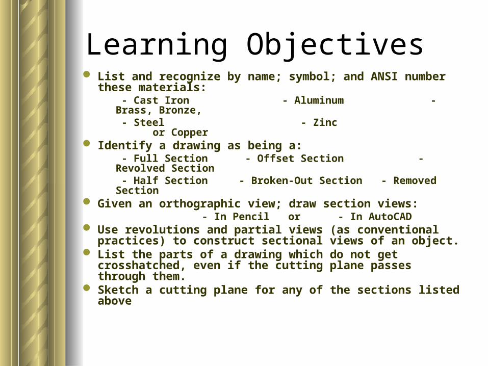
Learning Objectives List and recognize by name; symbol; and ANSI number
these materials: - Cast Iron - Aluminum - Brass, Bronze, - Steel - Zinc or Copper
Identify a drawing as being a: - Full Section - Offset Section - Revolved Section - Half Section - Broken-Out Section - Removed Section
Given an orthographic view; draw section views: - In Pencil or - In AutoCAD
Use revolutions and partial views (as conventional practices) to construct sectional views of an object.
List the parts of a drawing which do not get crosshatched, even if the cutting plane passes through them.
Sketch a cutting plane for any of the sections listed above
Readiness Assessment Test 9.2.1
Individually answer the following questions. You will be given 2 minutes:
Readiness Assessment Test 9.2.1
Individually answer the following questions. You will be given 2 minutes:
List 4 types of sectional views.
Team Discussion Item
As a team, discussing the following question:
What is the purpose of sectional views?
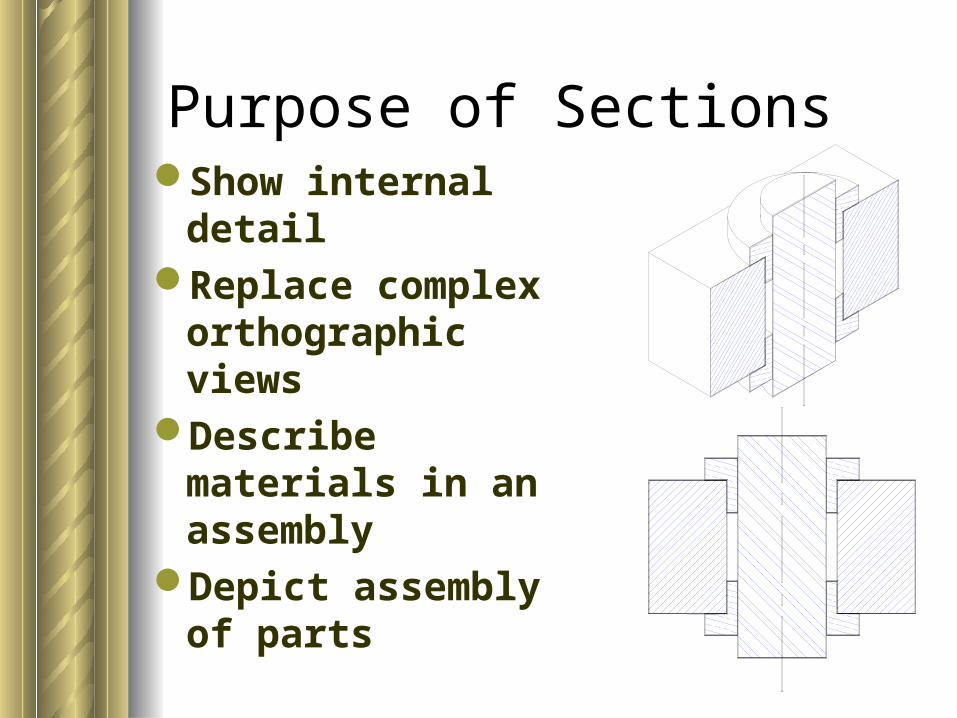
Purpose of SectionsShow internal detail Replace complex
orthographic viewsDescribe materials
in an assemblyDepict assembly of
parts
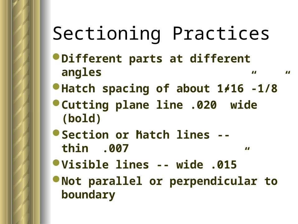
Sectioning PracticesDifferent parts at different anglesHatch spacing of about 1/16”-1/8” Cutting plane line .020” wide (bold)Section or hatch lines -- thin .007” Visible lines -- wide .015” Not parallel or perpendicular to
boundary
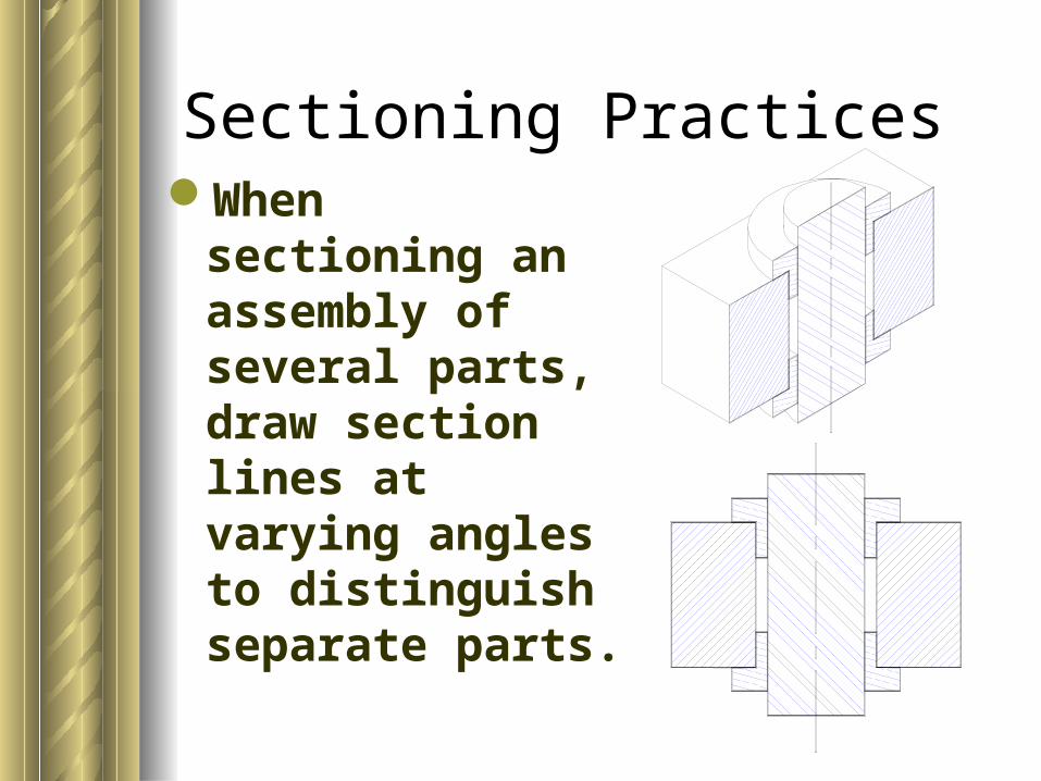
When sectioning an assembly of several parts, draw section lines at varying angles to distinguish separate parts.
Sectioning Practices
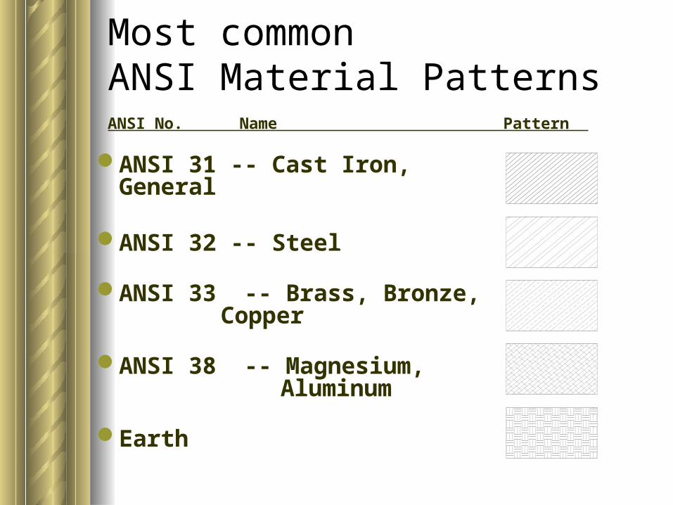
Most common ANSI Material Patterns
ANSI 31 -- Cast Iron, General
ANSI 32 -- Steel
ANSI 33 -- Brass, Bronze, Copper
ANSI 38 -- Magnesium, Aluminum
Earth
ANSI No. Name Pattern
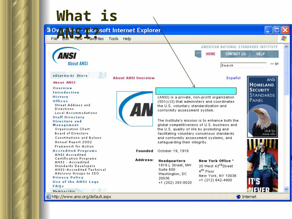
What is ANSI?
.
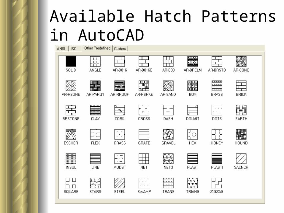
Available Hatch Patterns in AutoCAD
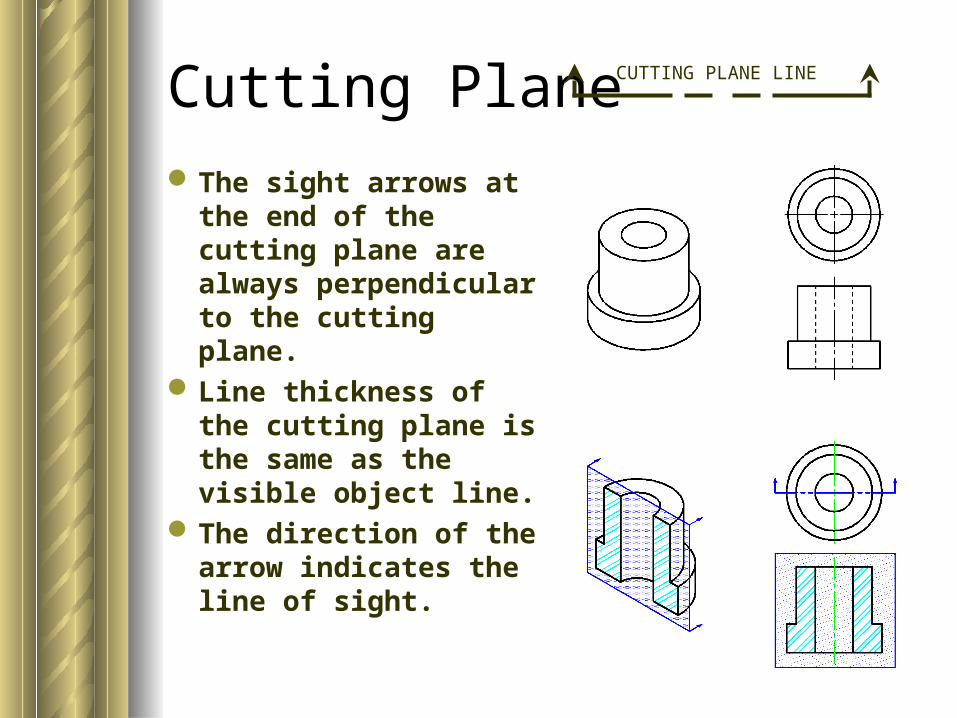
Cutting Plane
The sight arrows at the end of the cutting plane are always perpendicular to the cutting plane.
Line thickness of the cutting plane is the same as the visible object line.
The direction of the arrow indicates the line of sight.
CUTTING PLANE LINE
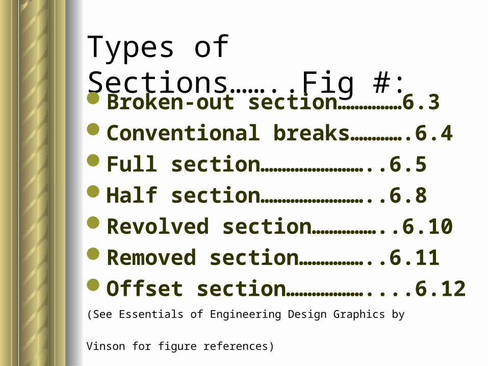
Types of Sections……..Fig #: Broken-out section……………6.3Conventional breaks………….6.4Full section……………………..6.5Half section……………………..6.8Revolved section……………..6.10Removed section……………..6.11Offset section………………....6.12
(See Essentials of Engineering Design Graphics by Vinson for figure references)
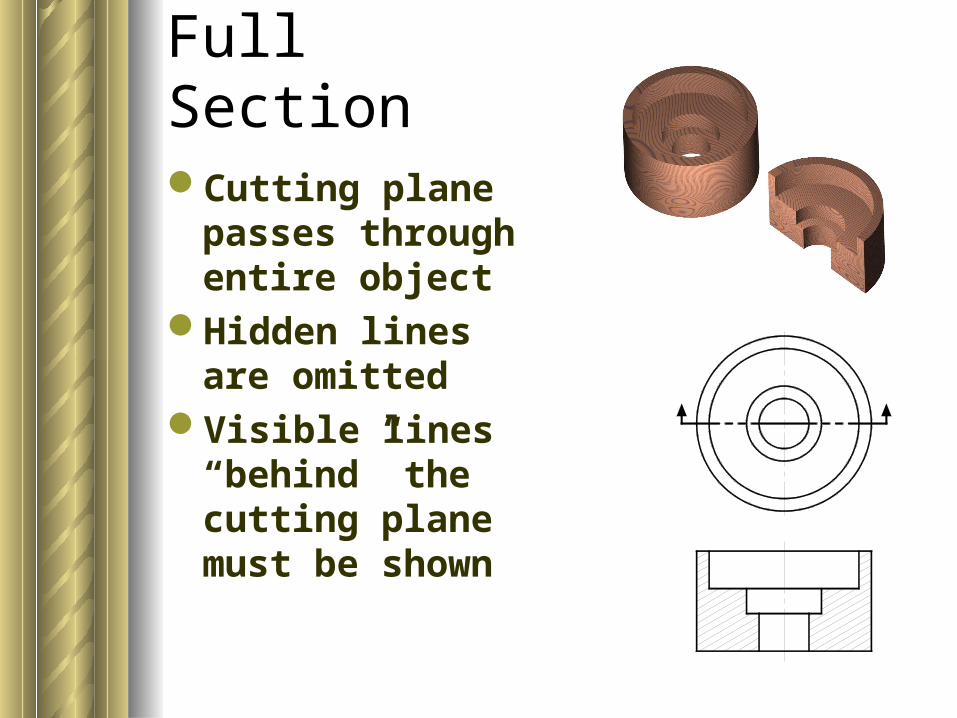
Full SectionCutting plane
passes through entire object
Hidden lines are omitted
Visible lines “behind” the cutting plane must be shown
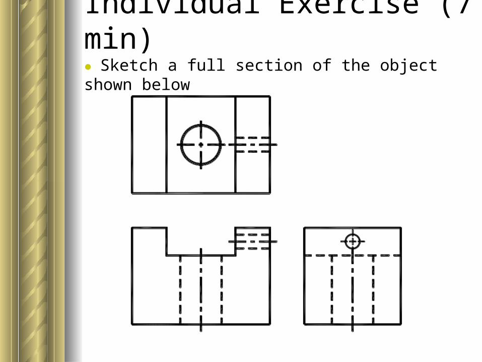
Individual Exercise (7 min)● Sketch a full section of the object shown below
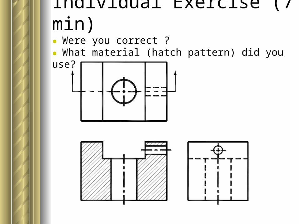
Individual Exercise (7 min)● Were you correct ?● What material (hatch pattern) did you use?
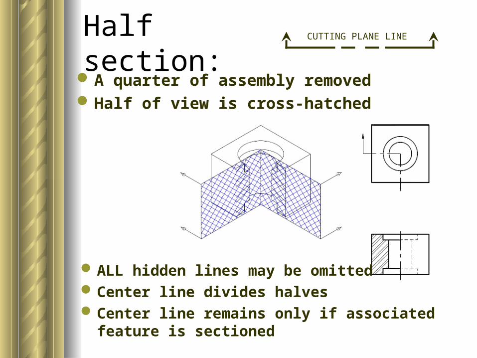
A quarter of assembly removedHalf of view is cross-hatched
Half section:
ALL hidden lines may be omittedCenter line divides halvesCenter line remains only if associated feature is
sectioned
CUTTING PLANE LINE
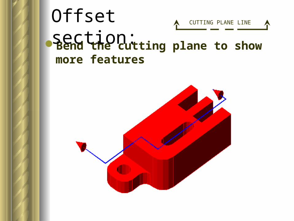
Bend the cutting plane to show more features
Offset section: CUTTING PLANE LINE
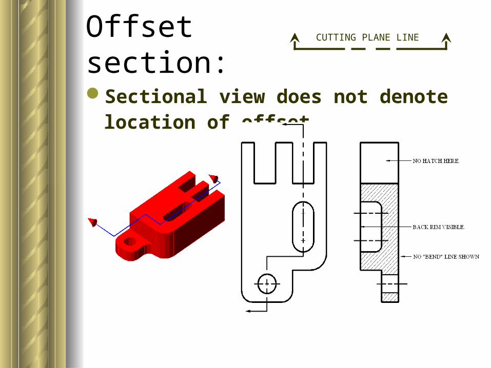
Sectional view does not denote location of offset
Offset section: CUTTING PLANE LINE
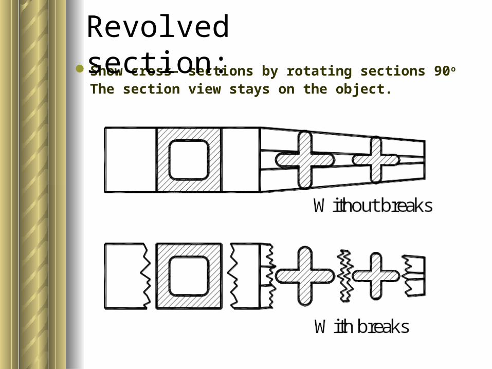
Show cross- sections by rotating sections 90o
The section view stays on the object.
Revolved section:
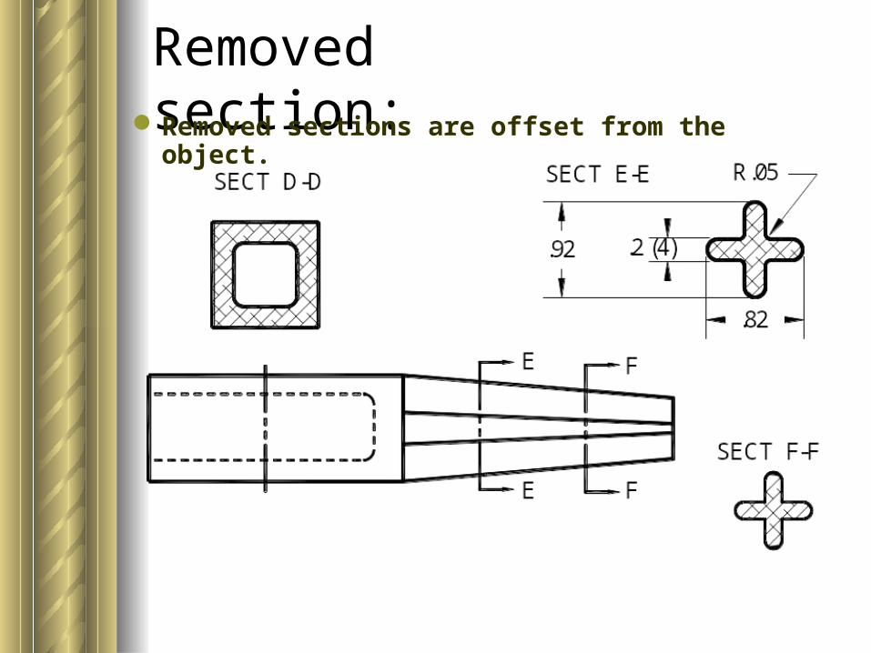
Removed section:Removed sections are offset from the object.
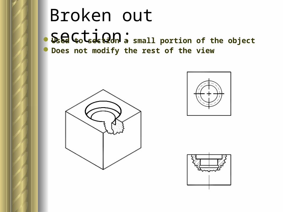
Broken out section:Used to section a small portion of the objectDoes not modify the rest of the view
Conventional PracticesConventional practices are
accepted drawing techniques that violate the rules of orthographic projection
They are designed to simplify orthographic drawing of complex features.
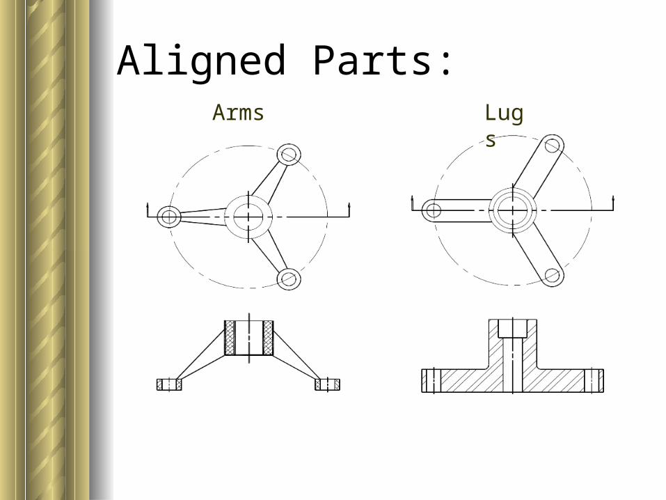
Aligned Parts: Arms Lugs
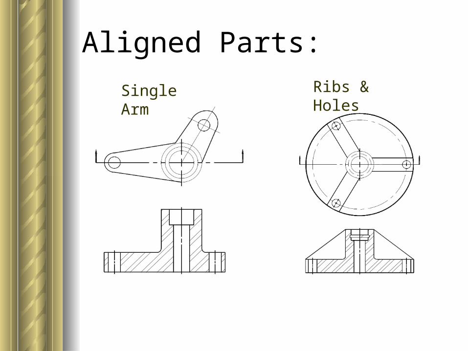
Aligned Parts:
Single Arm Ribs & Holes
Parts Not Sectioned.Don’t crosshatch (even though the
cutting plane may pass thru them):– Ribs, webs, spokes– Thin parts like gaskets– Ball bearings, roller bearings–Most vendor items:
Bolts Washers Shafts
Nuts Screws Pins
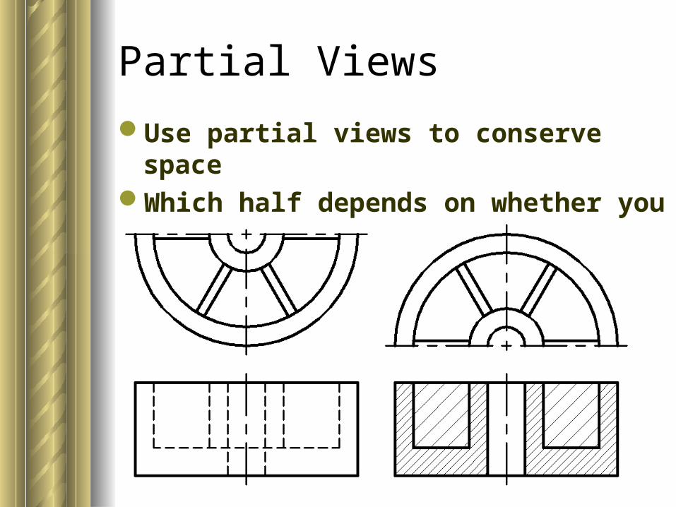
Partial Views
Use partial views to conserve spaceWhich half depends on whether you
section the view or not.
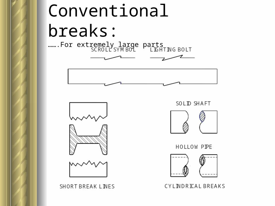
Conventional breaks: …….For extremely large parts
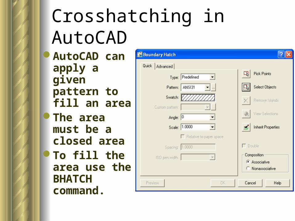
Crosshatching in AutoCAD
AutoCAD can apply a given pattern to fill an area
The area must be a closed area
To fill the area use the BHATCH command.
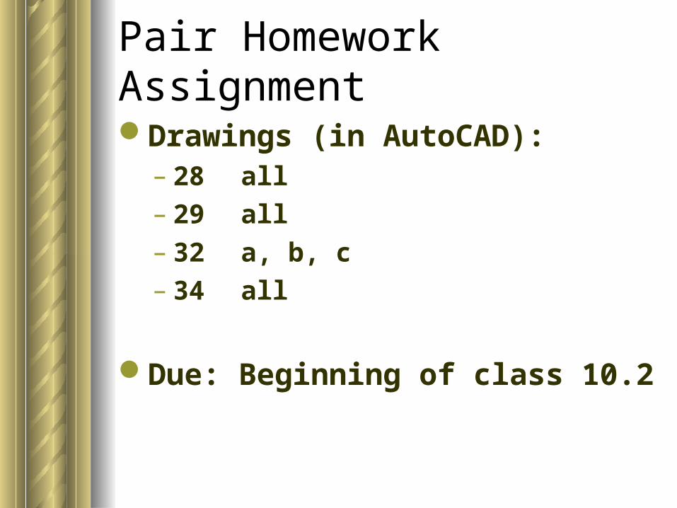
Pair Homework Assignment
Drawings (in AutoCAD):– 28 all– 29 all– 32 a, b, c– 34 all
Due: Beginning of class 10.2
Stop