English - FUJITSU GENERAL America, Inc.
20
English AIR CONDITIONER BRANCH BOX INSTALLATION MANUAL For authorized service personnel only. PART NO. 9380120001-06 Contents 1. SAFETY PRECAUTIONS ........................................... 2 2. ABOUT THE UNIT ...................................................... 4 2.1. Precautions for using R410A refrigerant .............. 4 2.2. Special tools for R410A........................................ 4 2.3. Accessories .......................................................... 4 3. SYSTEM CONFIGURATION ...................................... 5 4. INSTALLATION WORK............................................... 5 4.1. Selecting an installation location .......................... 5 4.2. Installation dimensions ......................................... 6 4.3. Installation of the unit ........................................... 8 5. PIPE INSTALLATION................................................ 12 5.1. Refrigerant pipe size and allowable piping length ................................................................. 12 5.2. Selecting the pipe material ................................. 13 5.3. Flare connection (Pipe connection).................... 13 5.4. Installing insulation ............................................. 15 6. ELECTRICAL WIRING ............................................. 16 6.1. Safety precautions for electrical wiring .............. 16 6.2. Selecting the cable and breaker ........................ 17 6.3. Wiring ................................................................. 17 7. TEST RUN AND CHECK LIST.................................. 20 8. MALFUNCTION DIAGNOSTICS ............................. 20 Español Français
Transcript of English - FUJITSU GENERAL America, Inc.

Engl
ish
AIR CONDITIONER BRANCH BOX
INSTALLATION MANUALFor authorized service personnel only.
PART NO. 9380120001-06
Contents1. SAFETY PRECAUTIONS ........................................... 2
2. ABOUT THE UNIT ...................................................... 4
2.1. Precautions for using R410A refrigerant .............. 4
2.2. Special tools for R410A ........................................ 4
2.3. Accessories .......................................................... 4
3. SYSTEM CONFIGURATION ...................................... 5
4. INSTALLATION WORK ............................................... 5
4.1. Selecting an installation location .......................... 5
4.2. Installation dimensions ......................................... 6
4.3. Installation of the unit ........................................... 8
5. PIPE INSTALLATION ................................................ 12
5.1. Refrigerant pipe size and allowable piping
length ................................................................. 12
5.2. Selecting the pipe material ................................. 13
5.3. Flare connection (Pipe connection).................... 13
5.4. Installing insulation ............................................. 15
6. ELECTRICAL WIRING ............................................. 16
6.1. Safety precautions for electrical wiring .............. 16
6.2. Selecting the cable and breaker ........................ 17
6.3. Wiring ................................................................. 17
7. TEST RUN AND CHECK LIST.................................. 20
8. MALFUNCTION DIAGNOSTICS ............................. 20
Espa
ñol
Fran
çais
9380120001-06 EN.indd 19380120001-06 EN.indd 1 6/16/2558 BE 8:19 PM6/16/2558 BE 8:19 PM

En-2
1. SAFETY PRECAUTIONS
IMPORTANT!Please Read Before StartingThis air conditioning system meets strict safety and operating standards.As the installer or service person, it is an important part of your job to install or service the system so it operates safely and effi ciently.
For safe installation and trouble-free operation, you must:
÷ Carefully read this instruction booklet before beginning. ÷ Follow each installation or repair step exactly as shown. ÷ Observe all local, state, and national electrical codes. ÷ Pay close attention to all danger, warning, and caution notices given in this manual.
When Installing......In a Ceiling or WallMake sure the ceiling/wall is strong enough to hold the unit’s weight. It may be necessary to construct a strong wood or metal frame to provide added support.
...In a RoomProperly insulate any tubing run inside a room to prevent “sweating” that can cause dripping and water damage to walls and fl oors.
When Connecting Refrigerant Tubing ÷ Keep all tubing runs as short as possible. ÷ Use the fl are method for connecting tubing. ÷ Apply refrigeration compressor oil (or equivalent ) used for the outdoor unit to the matching surfaces of the fl are and union tubes before connecting them, then tighten the nut with a torque wrench for a leak-free connection.
÷ Check carefully for leaks before opening the refrigerant valves. Refer to outdoor unit installation manual for proper procedure.
NOTE:Depending on the system type, liquid and gas lines may be either narrow or wide. Therefore, to avoid confusion the refrigerant tubing for your particular model is specifi ed as either “small” or “large” rather than as “liquid” or “gas”.
When Servicing ÷ Turn the power OFF at the main circuit breaker panel before opening the unit to check or repair electrical parts and wiring.
÷ Keep your fi ngers and clothing away from any moving parts.
÷ Clean up the site after you fi nish, remembering to check that no metal scraps or bits of wiring have been left inside the unit being serviced.
÷ After installation, explain correct operation to the customer, using the operating manual.
WARNING:This symbol refers to a hazard or unsafe practice which can result in severe personal injury or death.
CAUTION:
This symbol refers to a hazard or unsafe practice which can result in personal injury and the potential for product or property damage.
÷ Hazard alerting symbols
Electrical
Safety/alert
If Necessary, Get HelpThese instructions are all you need for most installation sites and maintenance conditions. If you require help for a special problem, contact our sales/service outlet or your certifi ed dealer for additional instructions.In Case of Improper InstallationThe manufacturer shall in no way be responsible for improper installation or maintenance service, including failure to follow the instructions in this document.
SPECIAL PRECAUTIONSWhen WiringELECTRICAL SHOCK CAN CAUSE SEVERE PERSONAL INJURY OR DEATH. ONLY A QUALIFIED, EXPERIENCED ELECTRICIAN SHOULD ATTEMPT TO WIRE THIS SYSTEM.
÷ Do not supply power to the unit until all wiring and tubing are completed or reconnected and checked.
÷ Highly dangerous electrical voltages are used in this system. Carefully refer to the wiring diagram and these instructions when wiring. Improper connections and inadequate grounding can cause accidental injury or death.
÷ Ground the unit following local electrical codes. ÷ Connect all wiring tightly. Loose wiring may cause overheating at connection points and a possible fire hazard.
DANGER
Never touch electrical components immediately after the power supply has been turned off. Electrical shock may occur. After turning off the power, always wait 5 minutes or more before touching electrical components.
9380120001-06 EN.indd 29380120001-06 EN.indd 2 6/16/2558 BE 8:19 PM6/16/2558 BE 8:19 PM
En-3
Engl
ish
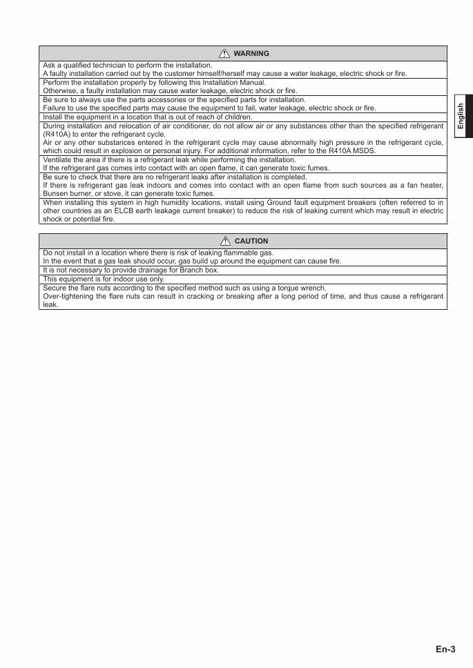
WARNINGAsk a qualifi ed technician to perform the installation.A faulty installation carried out by the customer himself/herself may cause a water leakage, electric shock or fi re.Perform the installation properly by following this Installation Manual.Otherwise, a faulty installation may cause water leakage, electric shock or fi re. Be sure to always use the parts accessories or the specifi ed parts for installation.Failure to use the specifi ed parts may cause the equipment to fail, water leakage, electric shock or fi re.Install the equipment in a location that is out of reach of children.During installation and relocation of air conditioner, do not allow air or any substances other than the specifi ed refrigerant (R410A) to enter the refrigerant cycle. Air or any other substances entered in the refrigerant cycle may cause abnormally high pressure in the refrigerant cycle, which could result in explosion or personal injury. For additional information, refer to the R410A MSDS.Ventilate the area if there is a refrigerant leak while performing the installation.If the refrigerant gas comes into contact with an open fl ame, it can generate toxic fumes.Be sure to check that there are no refrigerant leaks after installation is completed.If there is refrigerant gas leak indoors and comes into contact with an open flame from such sources as a fan heater, Bunsen burner, or stove, it can generate toxic fumes.When installing this system in high humidity locations, install using Ground fault equipment breakers (often referred to in other countries as an ELCB earth leakage current breaker) to reduce the risk of leaking current which may result in electric shock or potential fi re.
CAUTIONDo not install in a location where there is risk of leaking fl ammable gas.In the event that a gas leak should occur, gas build up around the equipment can cause fi re.It is not necessary to provide drainage for Branch box.This equipment is for indoor use only.Secure the fl are nuts according to the specifi ed method such as using a torque wrench.Over-tightening the fl are nuts can result in cracking or breaking after a long period of time, and thus cause a refrigerant leak.
9380120001-06 EN.indd 39380120001-06 EN.indd 3 6/16/2558 BE 8:19 PM6/16/2558 BE 8:19 PM
En-4
2. ABOUT THE UNIT
2.1. Precautions for using R410A refrigerant
The basic installation work procedures are the same as conventional refrigerant models.However, pay careful attention to the following points:1 Since the working pressure is 1.6 times higher than that of conventional refrigerant (R22) models, some of the piping
and installation and service tools are special. (See the table below.) Especially, when replacing a conventional refrigerant (R22) model with a new refrigerant R410A model, always replace
the conventional piping and fl are nuts with the R410A piping and fl are nuts.2 Be careful that foreign matter (oil, water, etc.) does not enter the piping than with refrigerant models. Also, when storing
the piping, securely seal the openings by pinching, taping, etc.
2.2. Special tools for R410A
Tool name Contents of change
Gauge manifoldPressure is high and cannot be measured with a conventional (R22) gauge. To prevent erroneous mixing of other refrigerants, the diameter of each port has been changed.It is recommended the gauge with seals –0.1 to 5.3 MPa (30 in.Hg to 768 psi) for high pressure. –0.1 to 3.8 MPa (30 in.Hg to 551 psi) for low pressure.
Charge hose To increase pressure resistance, the hose material and base size were changed.Vacuum pump A conventional vacuum pump can be used by installing a vacuum pump adapter.
Gas leakage detector Special gas leakage detector for HFC refrigerant R410A.
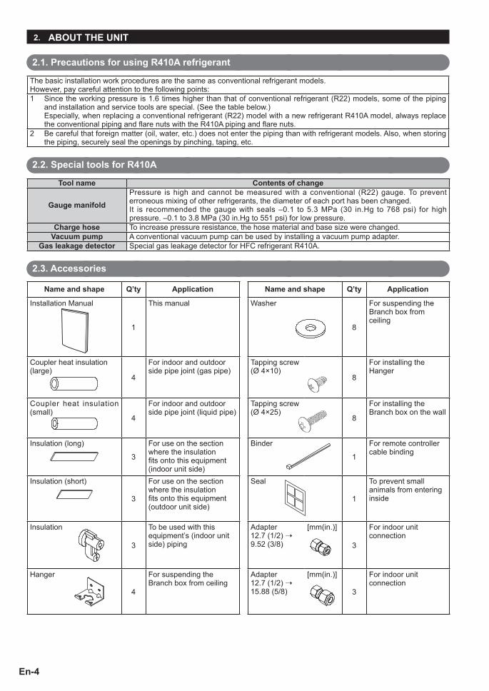
2.3. Accessories
Name and shape Q’ty Application Name and shape Q’ty Application
Installation Manual
1
This manual Washer
8
For suspending the Branch box from ceiling
Coupler heat insulation (large)
4
For indoor and outdoor side pipe joint (gas pipe)
Tapping screw (Ø 4×10)
8
For installing the Hanger
Coupler heat insulation (small)
4
For indoor and outdoor side pipe joint (liquid pipe)
Tapping screw (Ø 4×25)
8
For installing the Branch box on the wall
Insulation (long)
3
For use on the section where the insulation fi ts onto this equipment (indoor unit side)
Binder
1
For remote controller cable binding
Insulation (short)
3
For use on the section where the insulation fi ts onto this equipment (outdoor unit side)
Seal
1
To prevent small animals from entering inside
Insulation
3
To be used with this equipment’s (indoor unit side) piping
Adapter 12.7 (1/2) ➝ 9.52 (3/8)
[mm(in.)]
3
For indoor unit connection
Hanger
4
For suspending the Branch box from ceiling
Adapter 12.7 (1/2) ➝ 15.88 (5/8)
[mm(in.)]
3
For indoor unit connection
9380120001-06 EN.indd 49380120001-06 EN.indd 4 6/16/2558 BE 8:19 PM6/16/2558 BE 8:19 PM

En-5
Engl
ish
3. SYSTEM CONFIGURATION
For the installation method of indoor and outdoor units, refer to the installation manuals that come with them.
Breaker2
Breaker1
Breaker2
Breaker1
Breaker2
Breaker1
Breaker2
Breaker1
Breaker2 Circuit breaker (MOCP:Maximum Over Current Protection)
Breaker1 Earth leakage breaker
Piping
Power supply
Transmission line
Power supply and Transmission line
Branch boxPrimary unit : UTP-PU03ASecondary unit : UTP-PU03B
Branch box (Secondary2)
Branch box (Secondary1)Separation
tube
Separation tube
Branch box (Primary)
Indoor unit
Indoor unit
Indoor unit
Indoor unit
Indoor unit
Indoor unit
Indoor unit
Indoor unit
Outdoor unit
Power supply
Power supply
Power supply
Power supply
4. INSTALLATION WORK
2 to 8 indoor units can be connected.When installing just 1 branch box, be sure to use the primary unit. When installing multiple branch boxes, use both the primary unit and secondary units together.
4.1. Selecting an installation location
CAUTIONDo not install the Branch box in the following areas:• Area with high salt content, such as at the seaside. It will
deteriorate metal parts, causing the parts to fail or the unit to leak water.
• Area filled with mineral oil or containing a large amount of splashed oil or steam, such as a kitchen. It will deteriorate plastic parts, causing the parts to fail or the unit to leak water.
• Area that generates substances that adversely affect the equipment, such as sulfuric gas, chlorine gas, acid, or alkali. It will cause the copper pipes and brazed joints to corrode, which can cause refrigerant leakage.
• Area containing equipment that generates electromagnetic interference. It will cause the control system to malfunction, preventing the unit from operating normally.
• Area that can cause combustible gas to leak, contains suspended carbon fi bers or fl ammable dust, or volatile infl ammables such as paint thinner or gasoline. If gas leaks and settles around the unit, it can cause a fi re.
• Area where small animals may live. It may cause failure, smoke or fi re if small animals enter and touch internal electrical parts.
• Area where animals may urinate on the unit or ammonia may be generated.
÷ Install the branch box in a location that has strong support and no vibrations.
÷ Install in a location that has enough space for branch box installation.
÷ Install in a well-ventilated area.
÷ Install in a location that is not exposed to high temperatures or humidity over a long periods.
÷ Do not install the unit near a bedroom. Refrigerant noise may be heard from the piping.
÷ Refer to “4.2 Installation dimensions” for installation restrictions.
When installing the unit in a location such as above the ceiling or on the wall, follow the conditions below.
9380120001-06 EN.indd 59380120001-06 EN.indd 5 6/16/2558 BE 8:19 PM6/16/2558 BE 8:19 PM

En-6
4.2. Installation dimensions
÷ The branch box can be installed onto the wall or hanging from the ceiling. ÷ The branch box can be installed and set horizontally or vertically. ÷ Provide a service hole for maintenance and inspection purposes as shown in the fi gure below. ÷ It is not necessary to provide drainage for the Branch box. ÷ The slope of the top side must be within ±5° in all directions of the horizontal plane. ÷ Use M8 or M10 (5/16 in. or 3/8 in.) for the bolt size when hanging.
4.2.1. Horizontal installationBe sure that the top side faces upwards with the small pipe positioned lower than the large pipe.
44 (1-3/4)
469 (18-15/32)Hanger bolt pitch
40
40
Wall installation
25 (1)
148
Han
ger b
olt p
itch
256
(10-
3/32
)
(304
(13)
)24
(15/
16) Unit: mm (in.)
(5-2
6/32
)
(1-9/16)
(1-9/16)
Control box
Top
Top
Outdoor unit sideIndoor unit side
(838 (32-7/8))
433 (17-1/16)154
(6-1/16) 251 (9-7/8)
(304 (13))
9575
120
(4-3
/4)
85
195
(7-1
1/16
)
42
69 (2-23/32)
UN
IT A
UN
IT B
UN
IT C
(2-15/16) (3-3/4)
(3-1
1/32
)(1
-5/8
)
57 (2-1/4)
95(3-3/4)
95(3-3/4)
Top
Installation dimensions
Service access
850 (34) or more
(Service space) (Service space)
(Ser
vice
spa
ce)
300
(12)
or
mor
e
700
(28)
or m
ore
360 (15) or more 530 (21) or more
Top
Top
9380120001-06 EN.indd 69380120001-06 EN.indd 6 6/16/2558 BE 8:19 PM6/16/2558 BE 8:19 PM
En-7
Engl
ish
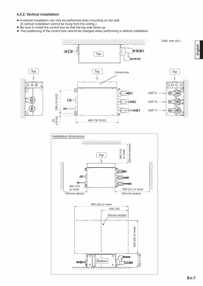
4.2.2. Vertical installation ÷ A vertical installation can only be performed when mounting on the wall. (A vertical installation cannot be hung from the ceiling.)
÷ Be sure to install the control box so that the top side faces up. ÷ The positioning of the control box cannot be changed when performing a vertical installation.
Unit: mm (in.)
Top
UNIT A
256
(10-
3/32
)24
(15/
16)
UNIT B
UNIT C
469 (18-15/32)
Control boxTop Top Top
Installation dimensions
360 (15) or more 530 (21) or more
300
(12)
or
mor
e
(Service space)(Service space)
(Ser
vice
spa
ce)
800 (32) or more400 (16)
Service access
500
(20)
or m
ore
200
(7-7
/8)
Top
Bottom
9380120001-06 EN.indd 79380120001-06 EN.indd 7 6/16/2558 BE 8:19 PM6/16/2558 BE 8:19 PM

En-8
4.3. Installation of the unit
WARNING
Perform installation in a location which can properly withstand the weight of the unit.Failure to install in a robust location or a faulty installment may cause the equipment to fail, water leakage, electric shock or fi re. During installation, secure the hanger bolt so it does not come off.
CAUTION
Be sure to provide adequate maintenance space when installing the unit above the ceiling.(Refer to the installation restrictions contained in “4.2 Installation dimensions”.)
4.3.1. Changing the positioning of the control box
CAUTION
Change the positioning of the control box on-site before performing the installation.
The positioning of the control box can be changed.(Only when installed horizontally. When vertically installed, the positioning cannot be changed.)
Bottom side To the opposite side
Control box
At time of shipment
Control box
Positioning after change
Bottom side
(1) Remove the screws (2 pieces) to remove the wiring cover.
Remove the tapes (4 places) on the main unit.
Bottom side
ScrewWiring cover
Tape (4 places)
(2) Remove the screws (2 pieces) to remove the control box cover.
Bottom side Control box cover
Screw
(3) Remove the screws (4 pieces). (Note: Do not remove the control box.)
Screw
Control box
Screw
Bottom side
(4) Remove the screws (4 pieces) to remove the bottom panel.
Screw
Bottom panel
Screw
Bottom side
9380120001-06 EN.indd 89380120001-06 EN.indd 8 6/16/2558 BE 8:19 PM6/16/2558 BE 8:19 PM

En-9
Engl
ish
(5) Remove the control box as shown in the fi gure, and then change the positioning to the opposite side.
(6) Attach the control box to the main unit as shown in the fi gure.
(7) Attach the bottom panel and secure it with the screws (4 pieces).
(8) Secure the control box with the screws (4 pieces).
(9) Attach the control box cover and secure it with the screws (2 places).
(10) Attach the wiring cover and secure it with the screws (2 places). Affi x the seals on the main unit (4 places).
To the opposite side
Remove the control box by lifting up and out through slots
Control box
The lead wire runs here
Control box
Insert and fi x the control box using the slots
Control boxBottom panel
Control box
Control box cover
Secure the wiring cover by inserting into the slots
Wiring cover
Seal (Accessory)
Affi x the seal so each hole (4 places) is covered.
9380120001-06 EN.indd 99380120001-06 EN.indd 9 6/16/2558 BE 8:19 PM6/16/2558 BE 8:19 PM

En-10
4.3.2-A. Fix the unit (When hanging from the ceiling)
CAUTION
Do not hang from the ceiling when performing a vertical installation.
(1) Secure the hangers (accessories) with the screws (2 pieces, Ø 4 x 10, accessories). (4 places)
Hanger (4 places)Screw
(2) Secure the attachment section with the hanging bolt. (Use M8 or M10 (5/16 or 3/8 in.) for the hanging bolt)
(3) Secure the hangers with hexagonal nuts (fi eld supply) and the washers (accessories) as shown in the fi gure below.
(4) Once you have checked the unit is fl at, fasten the hexagonal nuts. (The unit’s slope must be within ±5° in all directions.)
Hanging bolt (M8 or M10 (5/16 or 3/8))
Washers Hexagonal nuts (M8 or M10 (5/16 or 3/8))
9380120001-06 EN.indd 109380120001-06 EN.indd 10 6/16/2558 BE 8:20 PM6/16/2558 BE 8:20 PM

En-11
Engl
ish
4.3.2-B. Fix the unit (For wall installation)
<Horizontal installation>(1) Secure the hangers (accessories) with the screws
(2 pieces, Ø 4 x 10, accessories). (4 places)• Install the unit with its top side facing upwards.
<Vertical installation>(1) Secure the hangers (accessories) with the screws
(2 pieces, Ø 4 x 10, accessories). (4 places)• Install the unit with the control box facing upwards.
(2) For temporary mounting of the unit, install 2 of the Ø 4×25 screws in the wall, allowing the space of 5~10mm (3/16~3/8 in.) between the wall and the screw heads. Then hook the unit over these 2 screws.
(2) For temporary mounting of the unit, install 2 of the Ø 4×25 screws in the wall, allowing the space of 5~10mm (3/16~3/8 in.) between the wall and the screw heads. Then hook the unit over these 2 screws.
(3) After checking that the unit is fl at, secure and mount the branch box with the 8 screws (Ø 4 x 25, accessories) provided including the tapping screws.(The unit’s slope must be within ±5° in all directions.)
(3) After checking that the unit is fl at, secure and mount the branch box with the 8 screws (Ø 4 x 25, accessories) provided including the tapping screws.(The unit’s slope must be within ±5° in all directions.)
Top side
Hanger
Screw
Space between wall and head of screw: 5 ~ 10 mm (3/16 ~ 3/8 in.)
Tapping screws
469 (18-15/32 in.)Pitch for securing the tapping screws
SCREW SCREW
SCREW SCREW
Hanger
Screw
Control box
469 (18-15/32 in.)
SCREW SCREW
SCREW SCREW
Pitch for securing the tapping screws Tapping
screws
Space between wall and head of screw: 5 ~ 10 mm (3/16 ~ 3/8 in.)
9380120001-06 EN.indd 119380120001-06 EN.indd 11 6/16/2558 BE 8:20 PM6/16/2558 BE 8:20 PM

En-12
5. PIPE INSTALLATION
5.1. Refrigerant pipe size and allowable piping length
CAUTIONDo not mix with other air/gases except the specifi ed refrigerant for the refrigerant cycle. Ventilate the area if there is a refrigerant leak while performing the installation.Over-tightening when connecting the fl are fi ttings can result in cracking or breaking of the fl are nuts, and thus cause a refrigerant leak.For on-site piping insulation, be sure that the insulation covers the entire unit’s pipe connection. Pipe exposure can lead to water leaks from condensation and consequently cause burn injury from contact.During fl are connection, apply the refrigeration compressor oil (or equivalent) used for the outdoor unit to the fl are section.Secure the piping by taping it or performing pipe pinching so that impurities, water or dust do not penetrate inside the piping.
H1
a b c
de
f hg
i kjl m
H2
H3
H4
Separation TubeOutdoor
Unit
Indoor Unit1
Branch BoxBranch Box
Branch Box
(Primary)
(Secondary1) (Secondary2)
Indoor Unit2
Indoor Unit3
Indoor Unit4
Indoor Unit5
Indoor Unit6
Indoor Unit7
Indoor Unit8
Limitation m (ft) Diagram
Allo
wabl
e pi
pe le
ngth
(a
ctua
l pip
e le
ngth
)
Maximum total equivalent pipe length 115 or less (377) TotalBetween outdoor unit and the farthest indoor unit 70 or less (230) a + b + c + mBetween outdoor unit and branch boxes 55 or less (180) a + b + c + d + eBetween branch box and indoor unit Total 60 or less (197) f + g + h + i + j + k + l + m
Each unit Between 3-15 (10-49) f, g, h, i, j, k, l, mBetween outdoor unit and the first separation tube 5 or more (16) aBetween outdoor unit and branch box (when there is no separation tube) 5 or more (16) a+d
Allo
wabl
e he
ight
di
ffere
nce Between outdoor unit and indoor unit 30 or less (98) H1
Between outdoor unit and branch box 30 or less (98) H2Between branch box and branch box 15 or less (49) H3Between indoor unit and indoor unit 15 or less (49) H4
Note) Install the separation tube close to the branch box. Keep the pipe length for sections c, d, and e as short as possible.
Pipe size selection
Code Condition(model code of indoor unit)
Gas pipe [mm (in.)]
Liquid pipe [mm (in.)]
From the outdoor unit to the fi rst separation tube a — Ø 15.88 (5/8) Ø 9.52 (3/8)From the separation tube to the next separation tube b — Ø 15.88 (5/8) Ø 9.52 (3/8)From the separation tube to the branch box c, d, e — Ø 15.88 (5/8) Ø 9.52 (3/8)
From the branch box to the indoor unit f, g, h, i, j, k, l, m
7, 9, 12 Ø 9.52 (3/8)Ø 6.35 (1/4)18 Ø 12.70 (1/2)
24 Ø 15.88 (5/8)
9380120001-06 EN.indd 129380120001-06 EN.indd 12 6/16/2558 BE 8:20 PM6/16/2558 BE 8:20 PM

En-13
Engl
ish
5.2. Selecting the pipe material
WARNING
Be sure to perform fl are connection. It causes a malfunction and a fi re of this unit when connecting the pipes other than fl are connection (brazing etc.).
CAUTIONDo not use mineral oil on fl ared part.Prevent mineral oil from getting into the system as this would reduce the lifetime of the units.
5.3.1. Flaring(1) Cut the connection pipe to the necessary length with a
pipe cutter.(2) Hold the pipe downward so that cuttings will not enter
the pipe and remove any burrs.(3) Insert the fl are nut (always use the fl are nut attached to
the indoor and outdoor units respectively) onto the pipe and perform the fl are processing with a fl are tool.Use the special R410A fl are tool, or the conventional fl are tool.
(4) Protect the pipes by pinching them or with tape to prevent dust, dirt, or water from entering the pipes.
Pipe
DieA
B
Check if [L] is fl ared uniformly and is not cracked or scratched.
Pipe outside diameter[mm(in.)]
Dimension A [mm(in.)]Dimension B
[mm(in.)]Flare tool for R410A, clutch type
6.35 (1/4)0 to 0.5
(0 to 0.02)
9.1 (11/32)9.52 (3/8) 13.2 (17/32)
12.70 (1/2) 16.6 (21/32)15.88 (5/8) 19.7 (25/32)
When using conventional fl are tools to fl are R410A pipes, the dimension A should be approximately 0.5 mm (0.02 in.) more than indicated in the table (for fl aring with R410A fl are tools) to achieve the specifi ed fl aring. Use a thickness gauge to measure the dimension A.
Width across fl ats
Pipe outside diameter[mm(in.)]
Width across fl ats of Flare nut[mm(in.)]
6.35 (1/4) 17 (21/32)9.52 (3/8) 22 (7/8)
12.70 (1/2) 26 (1-1/32)15.88 (5/8) 29 (1-5/32)
Copper pipesIt is necessary to use seamless copper pipes and it is desirable that the amount of residual oil is less than 40 mg/10 m (0.004 oz/100 ft). Do not use copper pipes having a collapsed, deformed or discolored portion (especially on the interior surface). Otherwise, the expansion valve or capillary tube may become blocked with contaminants.As an air conditioner using R410A incurs pressure higher than when using conventional refrigerant (R22), it is necessary to choose adequate materials.Thicknesses of copper pipes used with R410A are as shown in the table. Never use copper pipes thinner than that in the table even when it is available on the market.
Thicknesses of Annealed Copper Pipes (R410A)Pipe outside diameter
[mm(in.)]Thickness[mm(in.)]
6.35 (1/4) 0.80 (0.032)
9.52 (3/8) 0.80 (0.032)
12.70 (1/2) 0.80 (0.032)
15.88 (5/8) 1.00 (0.039)
19.05 (3/4) 1.20 (0.047)
5.3. Flare connection (Pipe connection)
0-0.4
9380120001-06 EN.indd 139380120001-06 EN.indd 13 6/16/2558 BE 8:20 PM6/16/2558 BE 8:20 PM
En-14
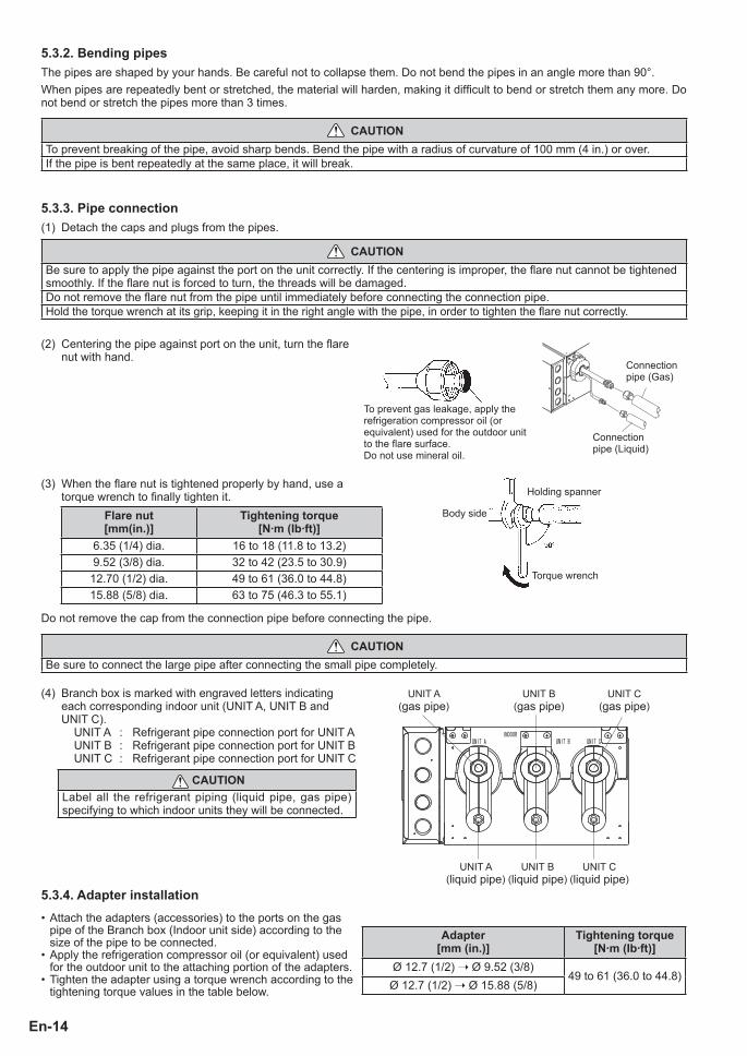
5.3.3. Pipe connection(1) Detach the caps and plugs from the pipes.
CAUTIONBe sure to apply the pipe against the port on the unit correctly. If the centering is improper, the fl are nut cannot be tightened smoothly. If the fl are nut is forced to turn, the threads will be damaged.Do not remove the fl are nut from the pipe until immediately before connecting the connection pipe.Hold the torque wrench at its grip, keeping it in the right angle with the pipe, in order to tighten the fl are nut correctly.
(2) Centering the pipe against port on the unit, turn the fl are nut with hand.
To prevent gas leakage, apply the refrigeration compressor oil (or equivalent) used for the outdoor unit to the fl are surface.Do not use mineral oil.
Connection pipe (Liquid)
Connection pipe (Gas)
(3) When the fl are nut is tightened properly by hand, use a torque wrench to fi nally tighten it.
Body side
Holding spanner
Torque wrench
Do not remove the cap from the connection pipe before connecting the pipe.
CAUTIONBe sure to connect the large pipe after connecting the small pipe completely.
(4) Branch box is marked with engraved letters indicating each corresponding indoor unit (UNIT A, UNIT B and UNIT C).
UNIT A : Refrigerant pipe connection port for UNIT AUNIT B : Refrigerant pipe connection port for UNIT BUNIT C : Refrigerant pipe connection port for UNIT C
UNIT A(gas pipe)
UNIT A(liquid pipe)
UNIT B(gas pipe)
UNIT C(gas pipe)
UNIT B(liquid pipe)
UNIT C(liquid pipe)
5.3.4. Adapter installation• Attach the adapters (accessories) to the ports on the gas
pipe of the Branch box (Indoor unit side) according to the size of the pipe to be connected.
• Apply the refrigeration compressor oil (or equivalent) used for the outdoor unit to the attaching portion of the adapters.
• Tighten the adapter using a torque wrench according to the tightening torque values in the table below.
Adapter[mm (in.)]
Tightening torque[N·m (Ib·ft)]
Ø 12.7 (1/2) ➝ Ø 9.52 (3/8)49 to 61 (36.0 to 44.8)
Ø 12.7 (1/2) ➝ Ø 15.88 (5/8)
Flare nut[mm(in.)]
Tightening torque[N·m (Ib·ft)]
6.35 (1/4) dia. 16 to 18 (11.8 to 13.2)9.52 (3/8) dia. 32 to 42 (23.5 to 30.9)
12.70 (1/2) dia. 49 to 61 (36.0 to 44.8)15.88 (5/8) dia. 63 to 75 (46.3 to 55.1)
CAUTIONLabel all the refrigerant piping (liquid pipe, gas pipe) specifying to which indoor units they will be connected.
5.3.2. Bending pipesThe pipes are shaped by your hands. Be careful not to collapse them. Do not bend the pipes in an angle more than 90°.When pipes are repeatedly bent or stretched, the material will harden, making it diffi cult to bend or stretch them any more. Do not bend or stretch the pipes more than 3 times.
CAUTIONTo prevent breaking of the pipe, avoid sharp bends. Bend the pipe with a radius of curvature of 100 mm (4 in.) or over.If the pipe is bent repeatedly at the same place, it will break.
9380120001-06 EN.indd 149380120001-06 EN.indd 14 6/16/2558 BE 8:20 PM6/16/2558 BE 8:20 PM

En-15
Engl
ish
5.4. Installing insulation
CAUTIONInstall heat insulation around both the gas and liquid pipes. Failure to do so may cause water leaks.Use heat insulation with heat resistance above 120 °C (248 °F). (Reverse cycle model only)In addition, if the humidity level at the installation location of the refrigerant piping is expected to exceed 70%, install heat insulation around the refrigerant piping. If the expected humidity level is 70-80%, use heat insulation that is 15 mm (19/32 in.) or thicker and if the expected humidity exceeds 80%, use heat insulation that is 20 mm (25/32 in.) or thicker.If heat insulation is used that is not as thick as specifi ed, condensation may form on the surface of the insulation. In addition, at 20 °C (68 °F), use heat insulation with heat conductivity of 0.045 W/(m·K) or less.
5.4.1. Piping insulation(1) Install the coupler heat insulation (large and small) and insulation (long and short) on each pipe as shown in the fi gures
below.(2) Attach the butting surface with no gap to eliminate any gap between the insulations.(3) During the pipe insulation work, prevent air from getting inside the insulation with an adhesive tape (fi eld supply).
(A) Indoor unit side
Coupler heat insulation (large)
Butting surfaces
Coupler heat insulation (small)
Adhesive tape (fi eld supply)
Insulation (long)
Adhesive tape (fi eld supply)
Adhesive tape (fi eld supply)
(B) Outdoor unit side
Coupler heat insulation (small)
Coupler heat insulation (large)
Butting surfacesInsulation (short)
Adhesive tape (fi eld supply)
Insulation (short)
Insulation (short)
Insulation (short) x 2(cover with 2 pieces of insulation)
[First piece]
[Second piece]
5.4.2. Non-connecting pipes(1) Install the coupler heat insulation (large and small) and
insulation (long) as shown in the fi gure on the right.(2) Apply an adhesive tape (fi eld supply) to prevent air from
getting inside the insulation.
Insulation (long)Adhesive tape (fi eld supply)
Adhesive tape (fi eld supply)
9380120001-06 EN.indd 159380120001-06 EN.indd 15 6/16/2558 BE 8:20 PM6/16/2558 BE 8:20 PM

En-16
6. ELECTRICAL WIRING
6.1. Safety precautions for electrical wiring
Power
WARNINGThe rated voltage of this product is 208/230 V A.C. 60 Hz.Before turning on verify that the voltage is within the 187V to 264V range.Use a dedicated power circuit and breaker matched to the capacity of the total of Branch boxes and Indoor units ratings. (Install in accordance with standard.)Perform wiring work in accordance with standards so that the air conditioner can be operated safely and correctly.When installing this system in high humidity locations, install using Ground fault equipment breakers (often referred to in other countries as an ELCB earth leakage current breaker) to reduce the risk of leaking current which may result in electricshock or potential fi re.
CAUTIONWe suggest installing GFEB breakers (30 mA or greater) or follow local electrical code.The power source capacity must be the sum of the air conditioner current and the current of other electrical appliances. When the current contracted capacity is insuffi cient, change the contracted capacity.
Electrical wiring
WARNINGBefore starting work, check that power is not being supplied to all units.Match the terminal board numbers and connection cable colors with those of the outdoor unit and indoor unit.Erroneous wiring may cause burning of electric parts.Connect the connection cables fi rmly to the terminal board. Imperfect installation may cause a fi re.Always fasten the outside covering of the connection cable with the cable clamp. (If the insulator is chafed, electric leakage may occur.)Always connect the ground wire.Install the remote controller cables so that a hand cannot touch it directly.Be sure to always turn the power off fi rst before performing the installation.Otherwise, handling electrical parts without turning off the power fi rst may cause electric shock.Be sure to set up an earth (ground) during installation. An earth (ground) wire should not be connected to the gas pipe, water pipe, lightning rod, or telephone earth wiring (ground).A faulty earth can cause electric shock or fi re.Make sure all wiring connections are secure, do not bundle power cables together, and do not use extension cables or circular power strips.Otherwise, a faulty installation may cause excessive heat and electric shock or fi re.Use the specifi ed electrical wires for the wiring between the indoor unit and the branch box and for the power supply. Ensure proper connection of these wires and be sure to secure them in such manner that no external force of the electrical wires is applied to the terminals.Arrange the electrical wires between the indoor unit and the branch box and for the power supply in such manner that the structures such as the service cover do not rise, and then install the cover securely.
9380120001-06 EN.indd 169380120001-06 EN.indd 16 6/16/2558 BE 8:20 PM6/16/2558 BE 8:20 PM

En-17
Engl
ish
6.2. Selecting the cable and breaker
6.3. Wiring
WARNINGBe sure to install a breaker with the specifi ed capacity.Regulation of cables and breaker differs from each locality, refer in accordance with local rules.
Select the correct capacity of the power supply according to the load (total current value of the connected units).
Voltage rating 1Ø 208/230V (60Hz)Operating range 187-264V
Cable Cable size *1) RemarksPower supply cable 14AWG 2 cable + Ground, 1 Ø 208/230V
Connection cable 14AWG 3 cable + Ground, 1 Ø 208/230V
1) Selected sample: Select the correct cable type and size according to the country or region’s regulations. Max. wire length: Set a length so that the voltage drop is less than 2%. Increase the wire diameter when the wire length is long.
Breaker Specifi cation *2)Circuit breaker (MOCP) *4) Current : 15 (A)
Earth leakage breaker Leakage current : 30mA 0.1sec or less *3)
2) Select the appropriate breaker of the described specifi cation according to the national or regional standards.3) Select the breaker that enough load current can pass through it.4) MOCP: Maximum Over Current Protection
HOW TO CONNECT WIRING TO THE TERMINALS FOR STAND WIRING.(1) Use crimp-type terminals with insulating sleeves as
shown in the fi gure below to connect to the terminal block.(2) Securely crimp the crimp-type terminals to the wires
using an appropriate tool so that the wires do not come loose.
(3) Use the specifi ed wires, connect them securely, and fasten them so that there is no stress placed on the terminals.
(4) Use an appropriate screwdriver to tighten the terminal screws. Do not use a screwdriver that is too small, otherwise, the screw heads may be damaged and prevent the screws from being properly tightened.
(5) Do not tighten the terminal screws too much, otherwise, the screws may break.
(6) See the table below for the terminal screw tightening torques.
WARNINGUse crimp-type terminals and tighten the terminal screws to the specifi ed torques, otherwise, abnormal overheating may be produced and possibly cause heavy damage inside the unit.
Sleeve
Crimp-type terminal
Screw with special washer
Crimp-type terminal
Wire
Terminal block
Wire
Terminal board
Strip 10 mm (0.39 in.)
Tightening torqueM4 screw 1.2 to 1.8 N·m (0.9 to 1.4 lb·ft)
Screw with special washerCrimp-type terminal
6.3.1. Cable preparation
• Power supply cable : 3-core wire cable.• Connection cable : 4-core wire cable.
Keep the ground cable longer than the other cables.
20 mm (3/4 in.)
Ground cable Power supply cable or connection cable
40 mm (1-1/2 in.) or m
ore
9380120001-06 EN.indd 179380120001-06 EN.indd 17 6/16/2558 BE 8:20 PM6/16/2558 BE 8:20 PM

En-18
6.3.2 Wiring methodExample) Wiring diagram when 3 branch boxes and 8 indoor units are connected
Example 1)
1 2 3 1 2 3 1 2 31 2 3
1 2 31 2 31 2 3
1 2 3
1 2 3
1 2 31 2 3
1 2 31 2 3 1 2 3
1 2 31 2 3
1 2 31 2 3 1 2 3
BRANCH BOX
OUTDOOR UNIT
INDOOR UNIT A INDOOR UNIT B INDOOR UNIT C POWER
REMOTECONTROL
BRANCH BOX
INDOOR UNIT A INDOOR UNIT B INDOOR UNIT C
REMOTECONTROL
INDOOR UNIT A INDOOR UNIT B INDOOR UNIT C
REMOTECONTROL
BRANCH BOX
BRANCH BOX
BRANCH BOX1 BRANCH BOX2
POWER POWER
Indoorunit
Indoorunit
Indoorunit
Indoorunit
Indoorunit
Indoorunit
Outdoor unit
Disconnect switchConnection cable
Single-phase208/230V60Hz
Single-phase208/230V60Hz
Single-phase208/230V60Hz
Optionalterminal
Indoor unit
Indoor unit
Branch box (Primary) Branch box (Secondary1) Branch box (Secondary2)
(Optionalterminal)
(Optionalterminal)
Breaker2: Circuit breaker (MOCP)
Breaker1: Earth leakage breaker
Breaker2 Breaker2 Breaker2
Breaker1 Breaker1 Breaker1
Connection cable
w Select the proper power supply (capacity) and the disconnect switch according to the load (total current value of the units connected units).
Example 2)
1 2 3 1 2 3 1 2 31 2 3
1 2 31 2 31 2 3
1 2 3
1 2 3
1 2 31 2 3
1 2 31 2 3 1 2 3
1 2 31 2 3
1 2 31 2 3 1 2 3
OUTDOOR UNIT
INDOOR UNIT A INDOOR UNIT B INDOOR UNIT C POWER
REMOTECONTROL
BRANCH BOX
INDOOR UNIT A INDOOR UNIT B INDOOR UNIT C
REMOTECONTROL
INDOOR UNIT A INDOOR UNIT B INDOOR UNIT C
REMOTECONTROL
BRANCH BOX
BRANCH BOX
BRANCH BOX1 BRANCH BOX2
POWER POWER
BRANCH BOX
Indoorunit
Indoorunit
Indoorunit
Indoorunit
Indoorunit
Indoorunit
Outdoor unit
Disconnect switch
Single-phase208/230V60Hz
Optionalterminal
Indoor unit
Indoor unit
Branch box (Primary) Branch box (Secondary1) Branch box (Secondary2)
(Optionalterminal)
(Optionalterminal)
Breaker2: Circuit breaker (MOCP)
Breaker1: Earth leakage breaker
Breaker2
Breaker1
Connection cable
Connection cable
Junction box
w Select the proper power supply (capacity) and the disconnect switch according to the load (total current value of the units connected units).
9380120001-06 EN.indd 189380120001-06 EN.indd 18 6/16/2558 BE 8:20 PM6/16/2558 BE 8:20 PM
En-19
Engl
ish
Knockout hole (To UNIT C)
Knockout hole (To UNIT B)
Knockout hole (To Branch box (Secondary1))
Knockout hole (To Branch box (Secondary2))
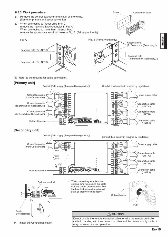
(3) Refer to the drawing for cable connection.
[Primary unit]Conduit (fi eld supply (if required by regulation)) Conduit (fi eld supply (if required by regulation))
Power supply cable
Connection cable(UNIT C)
Connection cable(UNIT B)
Connection cable(UNIT A)
Connection cable(from Outdoor unit)
Connection cable(to Branch box (Secondary1))
Connection cable(to Branch box (Secondary2))
Optional terminal
[Secondary unit]Conduit (fi eld supply (if required by regulation))
Conduit (fi eld supply (if required by regulation))
Power supply cable
Connection cable(UNIT C)
Connection cable(UNIT B)
Connection cable(UNIT A)
Connection cable(from Outdoor unit)
Optional terminal
Binder(Accessories)
Optional terminal
(4) Install the Control box cover.
• When connecting a cable to the optional terminal, secure the cable with the binder (Accessories). Seal the hole that passes the cable with putty so that there is no space.
Optional cable
Putty
CAUTIONDo not bundle the remote controller cable, or wire the remote controller cable in parallel, with the connection cable and the power supply cable. It may cause erroneous operation.
6.3.3. Work procedure Screw Control box cover
(1) Remove the control box cover and install all the wiring. (Same for primary and secondary units)(2) When connecting to indoor units B or C, remove the matching knockout holes in Fig. A.
When connecting to more than 1 branch box, remove the appropriate knockout holes in Fig. B. (Primary unit only)
Fig. B (Primary unit only)Fig. A
9380120001-06 EN.indd 199380120001-06 EN.indd 19 6/16/2558 BE 8:20 PM6/16/2558 BE 8:20 PM

En-20
¶ Lit (n) Flashing (number of fl ashing)‡ Unlit
Normal statusGreen Red
CommentLED401 LED402 LED403 LED404 LED405
¶ ‡ ‡ ‡ ‡ The branch box is functioning properly.
Error statusGreen Red
Error descriptionLED401 LED402 LED403 LED404 LED405
¶ ¶ ¶ ¶ ¶ Connected combination error¶ ¶ ¶ ¶ ‡
Power frequency error¶ ¶ ¶ ‡ ¶
Branch box
identifying display
Primary unit
: (1)
Secondary unit1: (2)
Secondary unit2: (3)
(1) ‡ ‡ ‡ EEPROM access error(2) ‡ ‡ ‡ Model information error
(3) ‡ ‡ ‡
• Serial communication error between outdoor unit and branch box
• Serial communication error between branch boxes(4) ‡ ‡ ‡ Serial communication error between branch boxes
(5)
¶ ‡ ‡Serial communication error between Indoor Unit A and branch box
‡ ¶ ‡Serial communication error between Indoor Unit B and branch box
‡ ‡ ¶Serial communication error between Indoor Unit C and branch box
(6)¶ ‡ ‡ Indoor Unit A, liquid pipe thermistor error (CN309)‡ ¶ ‡ Indoor Unit B, liquid pipe thermistor error (CN309)‡ ‡ ¶ Indoor Unit C, liquid pipe thermistor error (CN310)
(7)¶ ‡ ‡ Indoor Unit A, gas pipe thermistor error (CN309)‡ ¶ ‡ Indoor Unit B, gas pipe thermistor error (CN309)‡ ‡ ¶ Indoor Unit C, gas pipe thermistor error (CN310)
(8)¶ ‡ ‡ Indoor Unit A, EEV control error (CN305)‡ ¶ ‡ Indoor Unit B, EEV control error (CN306)‡ ‡ ¶ Indoor Unit C, EEV control error (CN307)
(9) ‡ ‡ ‡ Remote controller communication error
7. TEST RUN AND CHECK LIST
Conduct the check run and test run according to the Installation Manual of the outdoor unit.Check the following items before conducting the check run and test run.
Check Item Check Column Troubles in the event of failureHas the branch box been installed fi rmly? Drop, vibration or noiseWas there any refrigerant leak found through a refrigerant leak inspection? Function stop, no cooling or no heating
Has the insulation been perfectly installed on the pipes and pipe joints without any gap? Water leak
Has the piping been installed properly? Unable to operateHas the wiring been installed properly? Unable to operateWas power cable that meets the specifi cations used? Fire or unable to operateWere breakers that meets the specifi cations used? Fire or unable to operateHas proper grounding been performed? Electric shock or fi re
8. MALFUNCTION DIAGNOSTICS
When an error occurs, an error description displays in the LED (No. 401 ~ 405).
9380120001-06 EN.indd 209380120001-06 EN.indd 20 6/16/2558 BE 8:20 PM6/16/2558 BE 8:20 PM