Engineering the Lee Tunnel and Shafts through Chalk at Depth
79
Engineering the Lee Tunnel and Shafts through Chalk at Depth Peter Jewell CH2M HILL – Project Management Team Matthew Bellhouse Bachy Soletanche - MVB JV Presentation to the Engineering Group of the Geological Society of London (EGGS) and the British Tunnelling Society (BTS) Wednesday 29 January 2014
Transcript of Engineering the Lee Tunnel and Shafts through Chalk at Depth

Engineering the Lee Tunnel and Shafts through Chalk at Depth Peter Jewell CH2M HILL – Project Management Team Matthew Bellhouse Bachy Soletanche - MVB JV Presentation to the Engineering Group of the Geological Society of London (EGGS) and
the British Tunnelling Society (BTS)
Wednesday 29 January 2014

Engineering the Lee Tunnel and Shafts through Chalk at Depth
• Introduction to the Lee Tunnel Project
• Geological Features
• Engineering the Shafts
• Engineering the Main Tunnel
• Concluding Remarks

Introduction to the Lee Tunnel Project
•Currently under construction in the London Borough of Newham, the Lee Tunnel will form the first section of the eventual Thames Tideway Tunnel system.
•The Lee Tunnel will receive storm water flows from the Abbey Mills Pumping Station complex and store them until they can be pumped out at Beckton Sewage Treatment Works.
•The Lee Tunnel project was commenced in 2010 and is scheduled for completion by 2016.
•6.9km long, it is the deepest tunnel ever to be constructed beneath London with five of London’s largest diameter shafts. Main tunnel construction was almost entirely through Chalk.
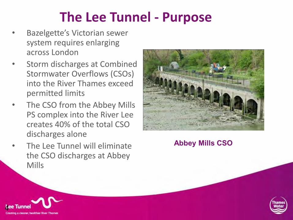
• Bazelgette’s Victorian sewer system requires enlarging across London
• Storm discharges at Combined Stormwater Overflows (CSOs) into the River Thames exceed permitted limits
• The CSO from the Abbey Mills PS complex into the River Lee creates 40% of the total CSO discharges alone
• The Lee Tunnel will eliminate the CSO discharges at Abbey Mills
4
The Lee Tunnel - Purpose
Abbey Mills CSO

5
Lee and Thames Tideway Tunnels

Lee Tunnel and Shafts
West East

• The Lee Tunnel will operate
as a self contained system prior to completion of the full Thames Tideway Tunnel system
• Shaft F will transfer storm flows from Abbey Mills Stations A and F to main tunnel
• Tideway Pumping Station will utilise one from six pumps of 3.05 cumec/s capacity to lift the effluent 87m to the Beckton STW
• Eventually the Thames Tideway Tunnel system will utilise four of these six pumps
7
The Lee Tunnel in Operation

8
Lee Tunnel – Contract
•Overall Budget of £677m
•Design and Construct Contract based on Employer Reference Design
•NEC (New Engineering Contract) 3rd Edition Option C – Activity Schedule • Awarded to MVB – Consortium of Morgan Sindall, Vinci Construction Grands Projets, Bachy Soletanche Limited. First tier designers are Mott Macdonald and Morgan Sindall Underground Services •Contract oversight by Project Management Team (PMT) led by CH2M HILL, supported by AECOM and others
•Collaborative working between all parties to the Contract via a Partnering Agreement

Lee Tunnel Construction Progress
• Four shafts completed. Shaft G diaphragm walls constructed
• 8.9m diameter slurry TBM
prescribed – successful choice
• ‘Busy Lizzie’ lowered into launch shaft in December 2011
• Initial ‘Short Launch’ mode tunnelling until trailing gantries installed in August 2012
• Connection shaft traversed in January 2013
• Tunnel drive completed in January 2014!
TBM Factory Test Visit May 2011


Lee Tunnel Excavation Completed
Congratulations!
Tunnelling Teams Support Teams

13
BREAK FOR MATTHEW’S SLIDES

Engineering the Shafts
• Diaphragm Wall Primary Linings
• Base Slabs
• Slipformed Secondary Linings
• Annulus Concrete


Diaphragm Wall Primary Linings
•Five shafts with completed internal diameters of 20m, 25m (3 no.) and 38m. •Over 100 no. individual panels with wall thicknesses between 1.2m and 1.8m and depths between 83m and 98m.
•Ground conditioning – For Overflow Shaft, first filling of existing chambers with 30,000 cubic metres of foam concrete, then coring to remove initial 15m.
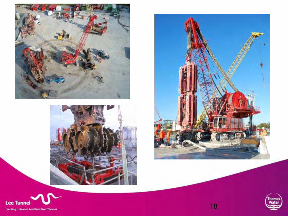
•Initial excavation using conventional diaphragm wall grab. Excavation through Lambeth group, Thanet Sand and Chalk using Hydrofraise.
•Specified requirement of 1 in 300 out of vertical tolerance achieved, assisted by real time inclinometer monitoring and the Koden system (electronic position sensor lowered on completion of each panel)
•Dedicated treatment plants to enable full recirculation of slurry mud.

Rotary drum cutters
Mud Pump
Inclinometer
Guide Frame
Mud to the desanding plant
Treated mud return to the trench
Hydrofraise Operation
18

1st Bite – 3 Bite
Primary

2nd Bite – 3 Bite Primary

Central Bite
– 3 Bite Primary

Cage Installation

Concreting

Single Bite Secondary Excavation

Diaphragm Wall Mud Treatment Plants

26
Reinforcement Cage Handling

Shaft Excavation

Lee Tunnel – Base Slabs
• Design:
- Groundwater pressure relief inside shafts, to prevent blow out of ground at shaft base
- Originally flat plates, refined to domes - 2m at sides to 4m in centre, other than for PS shaft (2.5m at sides to 5m in centre)
- Incorporation of reinjectable channels
- For pumping station shaft, sprayed waterproof membrane on blinding below base slab structure
• Construction:
- Reinforcement placed radially and circumferentially to enable maximum prefabrication
- Enabled construction programme to be reduced by 50%

Engineering the Lee Tunnel at Depth


Slipformed Secondary Linings Starting point Diaphragm walls not designed to be watertight, secondary lining must resist full groundwater pressure
Initial Approach - Rejected Jump form shuttered reinforced concrete cast directly against the diaphragm walls This lining would shrink on cooling and crack, then be pressurised by groundwater later Groundwater could potentially seep through the cracks and corrode the reinforced concrete
Alternative Approach - Adopted 700mm thick double sided slipformed fibre reinforced concrete chimney Cast on low friction base surface, so free to move horizontally Pre-compressed through placement of mass concrete in 700mm annular gap
Slipform rig reaching top of Overflow Shaft

Diaphragm wall primary lining
Stage 1

Double sided slipformed chimney internal lining
Diaphragm Wall
Stage 2

Mass concrete infill to annulus
Internal lining pre-compressed
Stage 3

Before operation, internal lining resists groundwater pressure
Stage 4
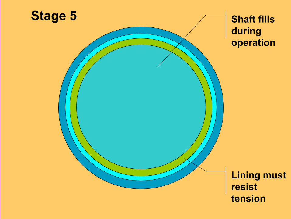
Shaft fills during operation
Stage 5
Lining must resist tension


Annulus Concreting


Engineering the Main Tunnel
• Slurry Tunnelling
• Slurry Treatment Plant
• TBM ‘Short Launch’
• Linings
• Barge Operations

1. Tunnel Face 2. Cutting Wheel 3. Supporting Liquid 4. Excavation Chamber 5. Bulkhead 6. Slurry Feed Line 7. Air Bubble 8. Submerged Wall 9. Working Chamber 10.Slurry Removal Line 11.Grid 12.Segmental Lining 13.Tailskin
Slurry Tunnelling Diagram

• The cutting wheel (2) rotates and removes material from the tunnel face (1). The material sinks in the supporting liquid (3).
• The excavation chamber (4) is separated from the working chamber (9) by the submerged wall (8). The material passes through a grid housing a crusher to the slurry removal line (10), sucking it out for treatment.
• The removed volume is replaced with fresh slurry from the feed line (6).
• The bulkhead (5) separates the TBM operational area at atmospheric pressure from the pressurised area.
Slurry Tunnelling Operation (1)

• The air bubble (7) in the working chamber sets the pressure of the supporting liquid. This pressurisation prevents loss of tunnel face stability.
• The excavation chamber is therefore completely filled with supporting liquid, but in the working chamber it normally rests just above axis.
• The compressed air regulating system maintains an adjustable set point pressure, in turn regulating pressure and flow fluctuations in the slurry lines.
Slurry Tunnelling Operation (2)


TBM Face Control Room

CAP TBM Control and Monitoring System
• Control Panel
• Ring Building
• Survey
• Daily Progress
• Grout Plant
• Slurry Circuit
• Slurry Pumps
• Slurry Plant Filter Presses
• Grease
• Soil (including extracted weights)
• Alarms
• Electrical Power Consumption
• Cutterhead Drive
• Expected Geology
Control Panel Screenshot
Geological Information Screenshot

Slurry Treatment Plant

Slurry Treatment Plant (STP)
• The function of the STP is to: - separate the excavated materials from the slurry which is mostly then recycled - separate off and treats the excess slurry ready for off-site disposal - add water, polymers and bentonite as required to the fresh slurry
• The STP has six main Sections: - Separation (scalping, desanding and desilting units) - Preparation of fresh slurry - Storage and transfer of desanded slurry - Preparation and dosing of lime milk to condition the slurry before pressing - Filter presses - Water management and pH neutalisation

Process Diagram
Separation
Slurry preparation
Desanded arisings
Filter press arisings
Filter presses
Water and pH neutralisation

Slurry Treatment Plant
•The scalping unit comprises one rotating screen, the Trommel, which removes the larger (greater than 8mm) material. •The pulp (less than 8mm) is transferred to three double compartment tanks and pumped to feed six first stage cyclones of 750mm diameter. •The overflowing products are further pumped to the three sets of 12 no. second stage cyclones of 250mm diameter. •The residual slurry is treated in 12 no. filter presses. The final products are cakes which drop into the muck bins beneath. •Most of the filtrate is recovered for reuse for slurry dilution and general washing. •Addition of lime milk leads to pH up to12. The fluid leaving the presses is sulphuric acid neutralised to pH in range 6.5 – 9.

Slurry Treatment Plant - Under Construction

Slurry Treatment Plant – In Operation

Slurry Treatment Plant – Filter Presses

Slurry Treatment Plant – Trommel

Slurry Treatment Plant – Cyclone Plant
Both primary and secondary cyclones have cylindrical then conical parts. Material is fed into the cylindrical parts tangentially and forms vortices. Heavier/coarser particles are pushed to the outside and move down into the conical part to exit as solids. The lighter/finer particles exit with the filtrate and continue to the filter presses.
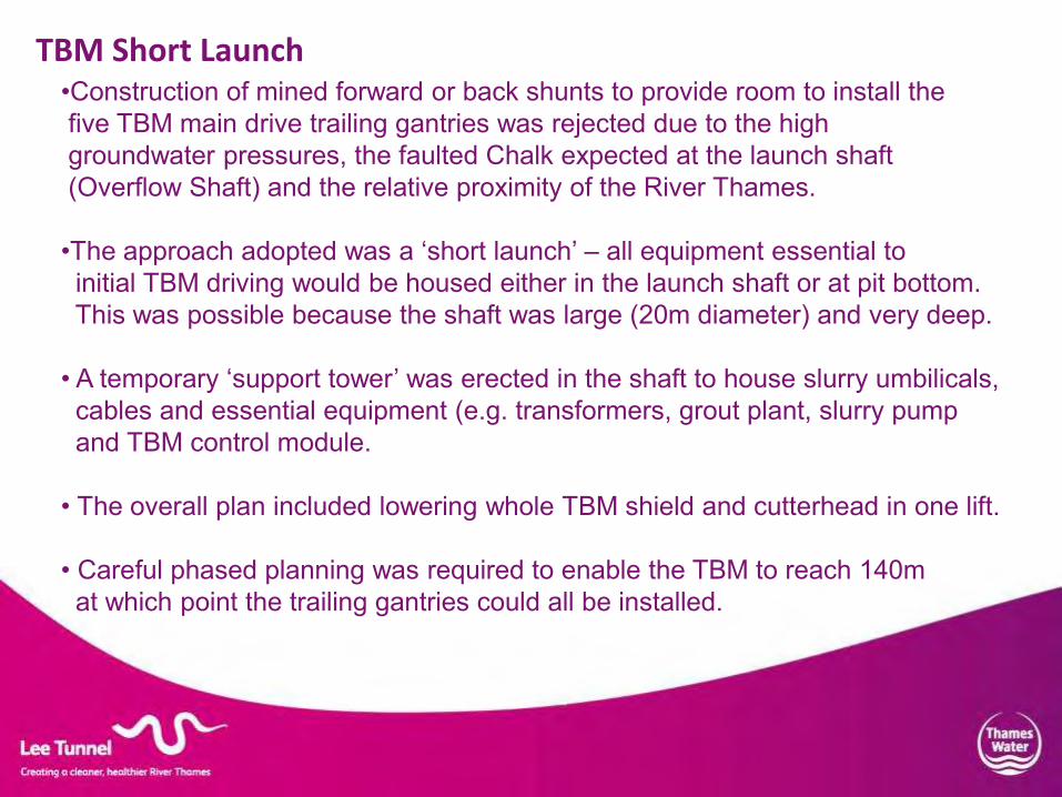
TBM Short Launch •Construction of mined forward or back shunts to provide room to install the five TBM main drive trailing gantries was rejected due to the high groundwater pressures, the faulted Chalk expected at the launch shaft (Overflow Shaft) and the relative proximity of the River Thames. •The approach adopted was a ‘short launch’ – all equipment essential to initial TBM driving would be housed either in the launch shaft or at pit bottom. This was possible because the shaft was large (20m diameter) and very deep. • A temporary ‘support tower’ was erected in the shaft to house slurry umbilicals, cables and essential equipment (e.g. transformers, grout plant, slurry pump and TBM control module. • The overall plan included lowering whole TBM shield and cutterhead in one lift. • Careful phased planning was required to enable the TBM to reach 140m at which point the trailing gantries could all be installed.

TBM Short Launch – Support Tower

TBM Short Launch – Wrapped Cabling

Trailing Gantry Installation

Primary Precast Segmental Lining •7.8m internal diameter steel and polypropylene fibre reinforced concrete precast segments 7 no. segments and a key designed as a universal ring 1.7m long and 350mm thick, designed to support full ground and groundwater pressure •Supplied by the Ridham Precast Concrete plant of Morgan Sindall
•EDPM (ethylene propylene diene monomer) rubber gaskets (from Datwyler Phoenix) cast into the segments •Primary and secondary grout injection

Secondary In-Situ FRC Lining
•7.2m ID steel fibre reinforced shuttered in-situ concrete 300mm thick
•Using 40kg/m3 dosage of Bekeart 5D fibres
•To be poured in two bespoke 270 degree 30m long articulated shutters •Plus 26no. bespoke 10m long 90 degree invert shutters
•Pumping and concrete quality trials in progress using trial invert shutters
Secondary Lining Shutters Under Construction

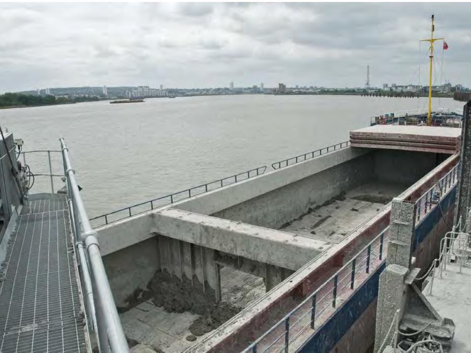
Barge Operations – Beckton and Abbey Mills
•All main tunnel spoil removed by barges from existing jetty at Beckton STW •Beckton barges of capacity range 500 to 2000 tonnes •Spoil destinations: - Mucking Landfill Site (Cory Environmental) - for restoration - Northfleet Embankment East - for land raising - Pitsea Landfill (Veolia ES) - for restoration - Tilbury Docks to East Tilbury Quarry (Walsh) •Abbey Mills D-wall and Shaft F spoil removed by barges of 250 to 500 tonnes capacity
Barge Operations at Beckton Jetty


Conveyor System to Jetty


Concluding Remarks - Geology


Concluding Remarks - Geology

Concluding Remarks - Geology


Concluding Remarks
• Excavation of London’s deepest ever tunnel through Chalk under full hydrostatic groundwater pressures now completed.
• Known geological irregularities were successfully planned for. An unexpected occurrence (the Boundary Lane Pingo) presented a further challenge.
• Vertical tolerance requirements consistently achieved for five exceptionally deep and thick diaphragm walled shafts.
• Double slipformed FRC internal linings gave savings of c. 4000 tonnes of steel bar reinforcement, as well as a better engineering solution and programme savings.
• Further large savings of steel bar reinforcement were made by adopting FRC tunnel linings.

Lee Tunnel – Awards to Date Project •March 2012 – Institution of Civil Engineers London Association - Infrastructure Award - Greatest Contribution to London Award •May 2012 – Ground Engineering Awards - Health & Safety Award - Editor’s Award •April 2013 – David Clayton (MVB) - BTS Harding Prize Winner •December 2013 – Fleming Prize for Excellence in Geotechnical Engineering •Considerate Contractors – 2011 Bronze, 2012 Silver, 2013 Gold Thames Water Health & Safety Excellence Awards •2010/11 – Jamie Bradley (MVB) – Young Person Winner •2011/12 – Clothilde Boquet (MVB) – Young Person Winner •2012/13 – Dan Wildman (MVB) – Young Person Runner Up •2012/13 – Design Contribution Winner

Acknowledgements and Thanks
•Thames Water for permission to make this presentation
•The Geological Society and the British Tunnelling Society for co-hosting this evening
•All members of the Lee Tunnel Project Team who have assisted in the preparation of this presentation and in delivering the project to date
•To you the audience for making the journey to attend this evening

Engineering the Lee Tunnel and Shafts through Chalk at Depth
Questions
Please?