ENGINEERING TECHNICAL NOTESTECHNICAL REPORTS DATA ... · principles employed by the Huggenberger...
28
ENGINEERING TECHNICAL FIELD NOTESTECHNICAL REPORTS INFORMATION DATA RETRIEVALMANAGEMENT PROFESSIONAL DEVELOPMENT SYSTEM NUMBERS Field Notes A MAN AND HIS MOUSETRAPS ENERGY MANAGEMENT A BATHHOUSE TOILET FACILITIES SOLAR ATTIC DWELLING NATIONAL FOREST BOUNDARIES DESCRIBING WILDERNESS BOUNDARIES -COMMENTS ON METHODS CORNER FOREST SERVICE JANUARY-FEBRUARY qS5ýk US 1980 U.S. DEPARTMENT OF AGRICULTURE
Transcript of ENGINEERING TECHNICAL NOTESTECHNICAL REPORTS DATA ... · principles employed by the Huggenberger...

ENGINEERINGTECHNICAL FIELD NOTESTECHNICAL REPORTS
INFORMATION DATA RETRIEVALMANAGEMENTPROFESSIONAL DEVELOPMENT
SYSTEM
NUMBERS
Field NotesA MAN AND HIS MOUSETRAPS
ENERGY MANAGEMENTA BATHHOUSE TOILET FACILITIES
SOLAR ATTIC DWELLING
NATIONAL FOREST BOUNDARIESDESCRIBING WILDERNESS BOUNDARIES
-COMMENTS ON METHODS
CORNER
FOREST SERVICE JANUARY-FEBRUARYqS5ýk
US 1980
U.S. DEPARTMENT OF AGRICULTURE


ti
US
ENGINEERING FIELD NOTES
Volume 12 Numbers 1 2
Information contained in this publication has been developed for guidance of employees
of the United States Department of Agri culture-Forest Service its contractors and its
cooperating Federal and State agencies. The Department of Agriculture assumes norespon-sibilityfor the interpretation or use of this-information by other than its own employees.
The use of trade firm or corporation names in this publication is for the information and
convenience of the reader. Such use does not constitute an official endorsement or approval
of any product or service by the United States Department of Agriculture to the exclusion
of others that may be suitable.
The text in the publication represents the personal opinions of the respective author and
must not be construed as recommended or approved procedures mandatory instructions
or policy except by FSM references. Because of the type of material inthe publication all
engineers and engineering technicians should read each issue however this publication is
not intended exclusively for engineers.
FOREST SERVICEU.S. DEPARTMENT OF AGRICULTURE
Washington D.C. 20013

From the
Editor--PUBLISHINGSCHEDULES
We have had many difficulties in publishing anddis-tributingEngineering Field Notes during the past 6
months.
According to a report from San Dimas EDC Septembersissue reached some offices as late as January 15.October was a disaster articles came in late and theprinted copies were rejected twice because the GPOcontractors work was unacceptable. In November theletter permitting us to reprint the BIOMASS energyarticle went astray in the mail and the internalreview and approval cycle was delayed.
By early December the requirements of theCertifica-tionExamination Program were critical and variousprojects prevented field inputs. As a result wedecided not to publish in December and material wasmoved forward to this combined January-Februaryissue.
We regret the necessity for our schedule changes andhope we can publish more promptly during the remainderof the year. And we thank those in the field whocalled to express concern and their interest in FieldNotes.
--Gordon L. Rome February 1 1980
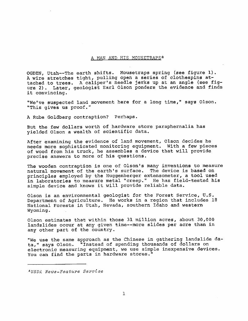
A MAN AND HIS MOUSETRAPS
OGDEN Utah--The earth shifts. Mousetraps spring see figure 1.A wire stretches tight pulling open a series of clothespinsat-tachedto trees. A calipers needle jerks up at an angle seefig-ure2. Later geologist Earl Olson ponders the evidence and findsit convincing.
Weve suspected land movement here for a long time says Olson.This gives us proof.
A Rube Goldberg contraption Perhaps.
But the few dollars worth of hardware store paraphernalia has
yielded Olson a wealth of scientific data.
After examining the evidence of land movement Olson decides heneeds more sophisticated monitoring equipment. With a few piecesof wood from his truck he assembles a device that will provideprecise answers to more of his questions.
The wooden contraption is one of Olsons many inventions to measurenatural movement of the earths surface. The device is based on
principles employed by the Huggenberger extensometer a tool usedin laboratories to measure metal creep. He has field-tested his
simple device and knows it will provide reliable data.
Olson is an environmental geologist for the Forest Service U.S.
Department of Agriculture. He works in a region that includes 18
National Forests in Utah Nevada southern Idaho and westernWyoming.
Olson estimates that within those 31 million acres about 30000landslides occur at any given time--more slides per acre than in
any other part of the country.
We use the same approach as the Chinese in gathering landslideda-tasays Olson. Instead of spending thousands of dollars onelectronic measuring equipment we use simple inexpensive devices.
You can find the parts in hardware stores.
USDA News-Feature Service
1

Yi
Figure 1.--OZson sets mousetrapthat springs when shifting ZandpuZZs the wire.
Figure 2.--Measuring the change indistance between two nuts glued torock.
During the past six years Olson has adapted about 100 common itemsto monitor landslides. Among his favorites are nuts bolts nailstongue depressors epoxy glue and measuring tapes see figure 3.
He has invented at least six devices that perform competitivelywith expensive electronic equipment. It would be difficult toes-timatthe amount of money his inventions have saved taxpayers hiscolleagues claim.
Forest managers need Olsons geologic information to determinesta-bilitof land for building roads developing skiing and otherre-sortmaking timber sales and protecting visitors. Hiscounter-partscollect similar data in many other National Forests.
2

Figure 3.--Olson hooks tape measure to nail in tree to measure
changes in distance.
Some of Olsons most promising inventions include a scissorsexten-someternow in use and a swing-arm device hell test in 1980. Hemakes the extensometer by bolting ordinary metal shelf bracketsto-getherin the shape of an X. Olson drives two points into the
ground and calculates land movement with a plumb bob hanging fromthe Xs center.
Olson makes the swing arm device of wood or metal. It can amplify
slope movement 100 times.
He also uses paraffin wax--another common substance--to detect land
movement. He pours the melted wax into holes in the ground oren-casesit in plastic tubes before putting it in the ground. Cracks
3

P P
in the hardened wax indicate land movement. His associates jokea-bouthis odd equipment and often refer to him as the junk man.
They laugh when they see what Im using says Olson but mostpeople are impressed by the results. They are amazed for examplethat two tongue depressors glued to a clothespin can show thatsev-eraltons of earth have shifted.
So far Olson has collected data on 7000 landslides. One of themost spectacular is the Manti Slide on the Manti-LaSal NationalForest in central Utah. In 1974 the side of a mountain startedmoving creating a dangerous situation for the city of Manti.
Rocks and debris tumbled onto the Cottonwood Landslide which hadbeen moving a few inches annually for several thousand years.Dur-ingone 24-hour period the mass moved 7.8 feet per hour.
We had visitors from all over the world said Olson. WestGer-manygave the slide special TV coverage. Scientists in Polandob-tainedaerial photographs of the area to study.
Electronic equipment was installed on the Manti Slide--at a cost of$7500 per unit. But Olson did much of the monitoring with hissim-plinexpensive devices and with aerial photography. He accuratelypredicted the slides course for the immediate future. Today theManti Slide is two miles long. Its upper part is still moving.
With the number of landslides we have in our region were goingto need many mousetraps and tongue depressors says Olson. Butwere collecting sound data inexpensively. The data is being usedin many parts of the world.
ABOUT THE AUTHOR
Bonnie Eldredge the author is a writer-editor for the ForestSer-viceU.S. Department of Agriculture at its regional office at
Ogden Utah.
4

ENERGY MANAGEMENT
SOLAR BATHHOUSE AND TOILET FACILITIES
Thomas F. Smith William A. SpeerStaff Engineer Regional Architect
R-8 R-8
Visitors to Bankhead National Forests Houston Recreation Area in
Alabama will soon be able to shower in water heated only by thesun.
Several years ago in response to energy conservation concernsRegion 8 adopted a policy of no longer providing warm watershowers. The policy was recently modified to allow use ofsolar-heatedwater for this purpose and a contract is underway forconstruction of a bathhouse as well as a four-unit toilet withshowers.
Both buildings will use solar collectors to provide warm water for
showers and the two solar systems are similar and very simple.Each system. consists of solar collectors mounted on the roofheated water storage tanks mounted overhead in the plumbingalley and a variable-flow circulating pump. Each includes
ordinary temperature and pressure relief valves air vent-vacuumbreakers and a differential temperature controller for the pumpoperation.
Each system has a temperature control valve which willautomati-callyproportion 60F 15.54C supply water from a well withsolar-heated water from the storage tank to deliver 85F 29.42Cwater to the showers considered to be the minimum desirable showerwater temperature. There are no provisions for auxiliary heat
in keeping with energy conservation concerns should the storagetank temperature drop below 85F 29.42C then 100 percent ofthe water will come from storage at whatever temperature storagewill provide. However the systems are capable of providing 85F29.42C water on all but the highest-use days.
Because the systems arent operated during the winter no freeze
protection is provided instead the systems will be drained atthe end of the recreation season.
5

cut onthis lineThe ourunit toilet has eight collectors two different sizes
i
for best use of the available roof area with a total area of
1246 square feet 674.4 square meters. The storage tank is 530 is
Lallons 2006.05 liters.cut on this line
The orientation of the bathhouse and placement of the solarcol-lectorson the bathhouse roof are somewhat unusual. The Regionutilized an existing design that met site needs rather than anew design however for this design site constraints dictatedan east-west rather than a north-south roof orientation.
Additionally more roof area was needed for solar collectors thanwas available on just one of the two roof slopes. An evaluationshowed that placing collectors on both sides of east-west facingroof slopes would work. The relatively flat roof slopes 18.5coupled with the fact that most public use will occur during theperiod of the year when the sun is at a high angle minimize theloss in collector efficiency.
The bathhouse has 10 collectors with a total collector a644 square feet 59.83 square meters and two 530-gallon1.4-12006.05-literstorage tanks. The toilet and bathhouse j a_Lbeginoperation in the 1980 recreation season.
For more information contact Tom Smith or Bill Speer at404-257-3367.C
6

SOLAR ATTIC DWELLING
Thomas F. Smith William A. SpeerStaff Engineer Regional Architect
R-8 R-8
Region 8 designed a 1300-square-foot solar attic dwelling thatis currently under construction as a VST project at the SchenckCivilian Conservation Center near Brevard North Carolina.
The solar attic dwelling employs a combination active/passivesystem that offers several advantages
1. It is simple to build using conventional materials thatare familiar to the Conservation Center work force.
2. It needs no expensive solar collectors attached to theroof the attic collects the suns heat providing up to 75per-centof the dwellings space-heating requirements.
3. Its solar heating system can be reversed thereby helpingto cool the house in summer.
4. Solar water heating is easily incorporated into thesys-tem.5. The solar system cost is low amounting to about 15per-centof the total cost-of the dwelling.
The solar attic design concept was developed by the Rural HousingResearch Unit at Clemson University. Several prototype houses hadbeen built in South Carolina and Georgia and R-8 design personnelconsulted with the Rural Housing Research Unit Staff beforeunder-takingdesign of the Forest Service dwelling.
This solar dwelling design has an integrated split-attic for solarheat collection and distribution and an underfloor rock thermal
storage and distribution system.
The attic is divided into an upper and a lower level. The upperlevel is basically an A frame with a pitch that favors maximumsolar heat collection from the suns winter position of latitude
7

plus 15 degrees. With the south-facing slope serving as adouble-glazedtransparent cover1 almost the entire inside surface ofthe upper attic--which is painted flat black--becomes the solarabsorber surface.
The solar attic has six operating modes three for heating andthree for cooling figs. 1 through 3. The system is controlled bydifferential thermostats that compare temperatures in the atticcollector in the dwelling and in the rock storage beneath thedwelling.
During the heating season the upper attic serves as the heatcollector its sealed from the lower attic which acts as areturn-air plenum. A heat pump evaporator coil that suppliesheat when the solar system does not is located in the upper attican air distribution blower is also located in the upper attic.
Sr
yoROCK THERMAL STORAGE
Figure 1.--Heating--attic to storageCooling--outside to storage
1
Glazing consists of 1-inch 2.54-centimeter tempered glass onthe outside of the rafters and polyester film on the inside of
the rafters.
8

II
1 1
CRAWLSPACE AIR PLENUM
Figure 2.--Heating--attic to houseCooling--outside to house
B2
B-1
1 1
l 1
Figure 3.--Heating--storage to house and auxiliary to houseCooling--storage to house and auxiliary to house
9

When the sun has warmed the air in the upper attic a differentialthermostat starts the air distribution blower thereby circulatingthe air through the rock storage if the house requires heat adif-ferentiathermostat starts the heat pump blower. The air is moved
by the distribution blower through the upper attic from the lowerattic through openings in the floor of the upper attic. Agravity-operatedpolyester flap attached to the top of each openingpre-ventsreverse circulation of cold air at night from the upper tothe lower attic.
Solar-heated air is ducted directly to the house and/or to the rock
storage under the house airflow arrows in figs. 1 2 3. Whenno solar heat is available during night hours or cloudy weatherstored heat is ducted from the rock storage to the dwellingsliving space by the heat-pump blower but in the reverse directionfrom which it is stored. This is because
Heated air enters the rock bin from the upper attic
chamber in the heat-storage mode at say 110F43.3C that is about the peak attic temperature
anticipated. The first rock it reaches rises to
this temperature. As the air travels horizontally
through the rock bin it gradually raises thetem-peratureof the rocks in the direction of airmove-mentuntil it exits via ducts for its return trip .
to the attic at say 68F 20.0C.
1To remove heat from storage the air flow is reversed. Then
fair enters storage at about 68F 20.0C and exits at 110F143.3C or whatever temperature the rock has attained since
lit reaches the hottest rock last. If storage is exhausted the
Lheat pump supplies the heat- _j
In the cooling season the ridge and eave vents are openedthere-byallowing cool air from the eaves to flow into the lower attic
and by convection to pass up through the upper attic and exit
through the continuous ridge vent.
During the cooling season the lower attic from the eaves to the
upper attic serves as a cool-air plenum. An important function of
the lower attic is serving as a thoroughly-insulated cavity that
separates the living space from the upper attic to reduce the heat
gain in the cooling season and heat loss in the heating season.
Monitoring done by the Rural Housing Research Unit on a prototype
2Tests by the Rural Housing Research Unit on thealready-con-structedprototype houses indicate that storage is sufficientfor three sunless days.
10

house shows that during the summer the lower attic stays 30F16.65C cooler than the temperatures in most conventional attics.
During the summer cooling season an air-intake vent to the outsideof the dwelling is opened to draw in cool nighttime air. The coolair does not enter either the upper or lower attic it is ducted
directly to the air distribution blower now isolated from the
upper attic chamber. This blower circulates cool air directlythrough the house with help from the heat-pump blower motor and/or cools the rock storage.
During the day cool air from rock storage is circulated throughthe house by the heat-pump blower. Air flow through storage is
reversed for the same reason as in heating except that incool-ingcycle the air reaches the coldest rock last. During the
cooling season the heat pump is turned on for short periods of
time as needed to control humidity and/or to providesupplemen-tarycooling.
IThe solar water heating system includes an air-to-water heat-
lexchanger differential thermostat circulating pump and solar
electric water tank. The heat exchanger consists of copper
Itubing with aluminum fins painted flat black this is attached
to the underside of the solar glazed rafters in the upper attic.I
plumbing is arranged for a direct circulation loop where
Ithe domestic water supply is circulated through the water tank. I
Freeze protection for the heat exchanger is provided by a drain-Idown solenoid-operated valve that opens when the upper attic
Ltemperature drops below35F_ 1 .67 __-_--------__-------ý/Waif nvi f.hý.c ý.nP
The living spaces are completely conventional and appear to have a
conventional forced-air heating/cooling system. The underfloor
space in the home is basically a crawl-space design the centralhalf contains the rock thermal storage and the remainingequally-dividedareas running with the length of the house serve asreturn-air plenums.
11


NATIONAL FOREST BOUNDARIES
DESCRIBING WILDERNESS BOUNDARIES
Some Comments on Methods in General Use
One Land Surveyors Viewpoint
C. C. Doak PLS Regional Land SurveyorR-3
NATURAL or CULTURAL FEATURES
Natural or manmade features that are readily identifiableon-the-groundare the most satisfactory boundaries to survey postadmin-isterand maintain. This type of boundary can be seenon-the-groundposted without survey and portrayed on maps it isrecog-izableon aerial photos and offers very little if any questionas to its exact position in the eyes of a court or any othercon-cernedparty. Examples of such features are ridge tops rim rockstravelways drainages railroad grades logging spurs and fencelines etc. Of course these features are not always availableand other methods must be used partially or entirely. Featuressuch as contours or toe of slope may be rather vague difficultto find through expensive survey and subject to challenge.
EXISTING PUBLIC LAND SURVEY NETWORK
Recent GLO or BLM Surveys
Describing wilderness boundaries along lines previously surveyed bythe GLO or BLM is satisfactory because these lines can be retracedand located on-the-ground. The monuments of GLO or BLM surveys aregenerally permanent-type monuments and recoverable. We are notreally concerned about the accuracy of the published bearing ordis-tancebetween these monuments if these monuments are on-the-ground.
It is also satisfactory to describe a boundary through the centerof the section from one-quarter corner to another it is anexpen-sivesurvey procedure however to break a section down into aliquot
13

parts and this would be necessary if the boundary makes a breakor turn within the section.
OZd GLO Contract Surveys
Land net surveys made before 1912 were performed by privatepracti-tionersunder contract. The survey methods were somewhat crude inmost instances allowable inaccuracies were great monuments wereoften not readily identifiable and in some instances were neverset. As in the areas we are designating as wilderness boundariesthe excessively erroneous and/or fraudulent surveys increased asthe terrain and conditions in general became more difficult.Loca-tingthese lines on a map is no problem as some cartographers havepreviously estimated their position on paper. To find the trueposition on-the-ground is another matter. To describe a boundaryalong these uncertain unfound lines creates an expensive and oftenunsuccessful operation and if the corners cannot be found youhave created a real monster--a line that you cannot find and cannotresurvey. The legal survey authority vested in the privatesur-veyorby any one of the public domain States only authorizes thesurvey or resurvey necessary for the determination of the limits ofpatented land. The only other survey authority to reestablish thelocation or relocation of a lost corner on the public survey systemis the Department of the Interior cadastral survey division of theBLM. Further the BLM program at present and for the past fewyears is dealing with the limits of public domain land--notadmini-strativboundaries or township subdivisions for the purposes ofidentification or disposal of public and private land. Original orresurveys wholly within public domain lands are virtually things ofthe past. Consequently I do not advise that you use an old surveyfor a tool unless you can live with it in its present condition orunless the limits of ownership is involved.
Unsurveyed Section Lines
Unsurveyed section lines portrayed on maps cannot be foundon-the-groundlegally or otherwise by anyone except the BLM. Their programhas previously been discussed. The unsurveyed land net on our mapsis based on a projected plan of the BLM to show the approximatelocation of the continuing survey of public lands. The intent wasto project only the approximate locations and numbering schemes ofrange lines township lines guide medians standard parallels andsubdivision breakdown all subject to change. Remember the BLM hassole jurisdiction at this time to make an original survey on therectangular system. Consequently my view is that this is the lastway I would describe anything that must be found and postedon-the-groundin a fashion that I could support.
14

METES AND BOUNDS
The metes and bounds system of describing land is the system ofselected directions and distances to meet a particular need thatis not fulfilled by the rectangular system for one or more of thereasons previously discussed. The metes and bounds system can betailored to enclose any parcel of land not described by therectan-gularsystem. My view is that the metes and bounds system be usedwhenever you do not have an adequate exisiting survey withon-the-groundmonuments surrounding your exact area of concern. Legalauthority is not required for these metes and bounds surveys as
patented land is not involved and the rectangular system of surveysis not altered extended or resurveyed. Anyone who can measurebearing and distances can legally perform this survey and post theboundaries.
SUMMARY
Posting wilderness boundaries requires finding the boundaryon-the-ground.When recognizable natural or cultural features are not
followed a survey is required a survey must follow a descriptionthe manner in which the description is written may make the taskroutine or involved and expensive and may require legal authorityand the use of the BLM which is not available under their presentprogram funding and manpower. Existing surveys should be usedor course if they meet your needs. If the survey cannot berecov-eredon-the-ground it cannot meet your needs as is the case ofnonexistent rectangular system survey.
With new survey technology and equipment such as the laser rangepole electronic distance measuring combination transit/distancemeasurer and programable computer total station together withairborn control ABC system satellite surveyor digitizersgyro-scopetheodolites and photogrammetric capabilities etc. it maybe advisable to make a new metes and bound survey rather than try tolive with the rectangular system existing or proposed. Once the
description is written we will live with it as well as the best wecan. However my last view is that you should coordinate withsur-veyorsRO or Forest if you are preparing a land description.
15

CORNER SEARCH IN NEBRASKA SANDHILLS
RoZZin C. Curd
Registered Land SurveyorNebraska National Forest
The Samuel R. McKelvie National Forest is located 40 miles 64.4kilometers southwest of Valentine Nebraska with the northbound-arysituated south of the Niobrara River. The terrain isrolling-to-roughsandhills with occasional ponderosa and broad leaf treesin the canyons the grass cover is native sandhill varieties. Thesoil texture is very fine sands with isolated pockets of clay and
loess-type material. The land has never been plowed or cultivated.
Under contract with the General Land Office in September 1877Frank M. Crowell surveyed the 8th Standard Parallel between
Twps. 32 33 Rgs. 30 31 32 33 34. He set 3-inch by 3-inch by
4-foot0.08-meter by 0.08-meter by 1.22-meter charred red cedar
posts with pits and mounds at half mile intervals his notesindica-tedthe use of bearing trees when available.
There are no records to indicate any resurveys of the 8th StandardParallel until 1979 except that--beginning in the 1920s--ForestService personnel had found several corners by ground search and
posted these corners.
In 1979 a Forest Service survey crew searched for corners on the
south boundary of T-33-N R-33-W 8th Std. Parallel. Using acom-binationof electronic measuring. equipment 200-foot 60.96-metertape T-2 theodolite and transit with compass and shovels the crewrecovered the corners shown in the photograph.
The corners were found by using transit with compass for directionand HP-3800 for distance to run random line. Beginning with oneknown corner a search was made at 1/2-mile 0.80-kilometerinter-valssetting a temporary wood stake the surrounding area wassearched by shovel the shovel was used in a near horizontalposi-tionto remove the grass cover and the top 3 inches 0.08 meter ofsoil.
Aluminum monuments and steel posts were set alongside cedar posts.Survey distances varied from the record from as much as 1 to 2
feet 0.3 to 0.6 meter per 1/2 mile 0.80 kilometer. Blowouts
17

LOCATION EVIDENCE
South 1/4 Section 34 Found pieces of splintered cedarand original hole light-coloredsand.
South 1/4 Section 31 Found 2-inch 0.05-meter diameterby 20-inch 0.51-meter long redcedar stake.
South 1/4 Section 32 Found a rotted 3-inch 0.08-meterdiameter by 18-inch 0.46-metercedar post set 14 inches 0.36meter into ground and charred atthe base.
1/4 Corner between On west line of T-32-N R-33-WSections 1 and 6 found a 3-inch 0.08-meterdia-Southof 8th/Std. meter by 3-1/2-foot 1.07-meterparallel long red cedar post. This post
was located on a slight northwestfacing slope 108 feet 32.92meters west of fence 10 inches0.25 meters of the post wasabove ground.
shifting sands and cattle have obliterated and destroyed some ofthe corners. Because cedar retains its color and scent theevi-denceof the original corners was apparent corners found aboveground have a light exterior color and are smooth surfaced. Thewell-drained sands of the area probably contributed to the longevityof the posts.
Stones were set for closing corners on the original survey in thetownship to the south three of these corners were searched forbut none was found.
In summary I believe a three-man survey party with two sharpshov-elsand a desire to find old corners will find some cedar posts.It should be noted that the Forest Service boundary fence variedfrom several feet to over 100 feet 30.48 meters from the trueline.
18
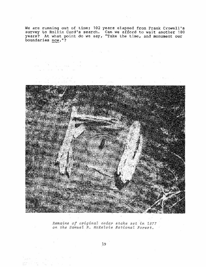
We are running out of time 102 years elapsed from Frank Crowellssurvey to Rollin Curds search. Can we afford to wait another 100
years At what point do we say Take the time and monument ourboundaries now.
Remains of original cedar stake set in Z877on the Samuel R. McKeZvie National Forest.
19

INVITATION TO READERS OFFIELD NOTES
Every reader is a potential author of an article for Field Notes. If you have a news item or
short article you would like to share with Service engineers we invite you to send it for
publication in Field Notes.
Material submitted to the Washington Office for publication should be reviewed by the
respective Regional Office to see that the information is current timely technicallyac-curateinformative and of interest to Forest Service Engineers FSM 7113. The length of
material submitted may vary from several short sentences to several typewritten pageshowever short articles or news items are preferred. All material submitted to theWashing-tonOffice should be typed double-spaced and ideally all illustrations should be original
drawings glossy prints or negatives.
Field Notes is distributed from the Washington Office directly to all Regional Station and
Area Headquarters Forests and Forest Service retirees. If you are not currently on the
mailing list ask your Office Manager or the Regional Engineering Technical Data Systems
Coordinator to increase the number of copies sent to your office. Copies of back issues are
also available from the Washington Office.
Field personnel should submitmaterial for publication or questions concerning Field Notes
to their Regional Coordinators
R-1 Melvin Dittmer R-4 Ted Wood R-9 Rich Wilson
R-2 Royal M. Ryser R-5 Paul Stutes R-10 Jack Van Lear
R-3 Juan Gomez R-6 Kjell Bakke WO Al ColleyR-8 Michael Martin
Coordinators should direct questions concerning format editing publishing dates and other
problems to
Forest Service - USDAEngineering Staff RP-E BldgAttn Gordon L. Rome Editor
P.O. Box 2417
Washington D.C. 20013
Telephone Area Code 703 235-8198
U. S. GOVERNMENT PRINTING OFFICE 1980 624-078/1581
1