Presentazione standard di PowerPoint - Terranova Instruments

IPS-E-IN-140(1)
This Standard is the property of Iranian Ministry of Petroleum. All rights are reserved to the owner. Neither whole nor any part of this document may be disclosed to any third party, reproduced, stored in any retrieval system or transmitted in any form or by any means without the prior written consent of the Iranian Ministry of Petroleum.
ENGINEERING STANDARD
FOR
LEVEL INSTRUMENTS
FIRST EDITION
FEBRUARY 2013
Feb. 2013
IPS-E-IN-140(1)
1
FOREWORD
The Iranian Petroleum Standards (IPS) reflect the views of the Iranian Ministry of Petroleum and are intended for use in the oil and gas production facilities, oil refineries, chemical and petrochemical plants, gas handling and processing installations and other such facilities.
IPS are based on internationally acceptable standards and include selections from the items stipulated in the referenced standards. They are also supplemented by additional requirements and/or modifications based on the experience acquired by the Iranian Petroleum Industry and the local market availability. The options which are not specified in the text of the standards are itemized in data sheet/s, so that, the user can select his appropriate preferences therein.
The IPS standards are therefore expected to be sufficiently flexible so that the users can adapt these standards to their requirements. However, they may not cover every requirement of each project. For such cases, an addendum to IPS Standard shall be prepared by the user which elaborates the particular requirements of the user. This addendum together with the relevant IPS shall form the job specification for the specific project or work.
The IPS is reviewed and up-dated approximately every five years. Each standards are subject to amendment or withdrawal, if required, thus the latest edition of IPS shall be applicable
The users of IPS are therefore requested to send their views and comments, including any addendum prepared for particular cases to the following address. These comments and recommendations will be reviewed by the relevant technical committee and in case of approval will be incorporated in the next revision of the standard.
Standards and Research department
No.17, Street14, North kheradmand
Karimkhan Avenue, Tehran, Iran .
Postal Code- 1585886851
Tel: 88810459-60 & 66153055
Fax: 88810462
Email: Standards@ nioc.ir
Feb. 2013
IPS-E-IN-140(1)
2
GENERAL DEFINITIONS
Throughout this Standard the following definitions shall apply.
COMPANY :
Refers to one of the related and/or affiliated companies of the Iranian Ministry of Petroleum such as National Iranian Oil Company, National Iranian Gas Company, National Petrochemical Company and National Iranian Oil Refinery And Distribution Company.
PURCHASER :
Means the “Company" where this standard is a part of direct purchaser order by the “Company”, and the “Contractor” where this Standard is a part of contract document.
VENDOR AND SUPPLIER:
Refers to firm or person who will supply and/or fabricate the equipment or material.
CONTRACTOR:
Refers to the persons, firm or company whose tender has been accepted by the company.
EXECUTOR :
Executor is the party which carries out all or part of construction and/or commissioning for the project.
INSPECTOR :
The Inspector referred to in this Standard is a person/persons or a body appointed in writing by the company for the inspection of fabrication and installation work.
SHALL:
Is used where a provision is mandatory.
SHOULD:
Is used where a provision is advisory only.
WILL:
Is normally used in connection with the action by the “Company” rather than by a contractor, supplier or vendor.
MAY:
Is used where a provision is completely discretionary.
Feb. 2013
IPS-E-IN-140(1)
3
CONTENTS: PAGE No.
1. SCOPE ............................................................................................................................................ 4 2. REFERENCES ................................................................................................................................ 4 3. UNITS .............................................................................................................................................. 5 4. GENERAL ....................................................................................................................................... 5 5. LOCALLY MOUNTED INDICATING GAUGES ............................................................................. 6
5.1 Tubular Gauge Glasses .......................................................................................................... 6 5.2 Armored-Type Gauge Glasses .............................................................................................. 7 5.3 Magnetic-Type Gauges ........................................................................................................... 9 5.4 Hydrostatic Head Pressure Gauges .................................................................................... 10 5.5 Differential Pressure Level Indicators ................................................................................ 11
6. LEVEL TRANSMITTERS .............................................................................................................. 11 6.1 Displacement Transmitters.............................................................................................. 11 6.2 Differential Pressure Transmitters .................................................................................. 12 6.3 Hydrostatic-head Transmitters ....................................................................................... 12 6.4 Nuclear Type Level Transmitters .................................................................................... 13 6.5 Ultrasonic-type Level Transmitters ................................................................................ 14 6.6 Capacitance-type Level Transmitters ............................................................................. 15
7. LOCALLY MOUNTED CONTROLLERS ...................................................................................... 16 8. REMOTE OR PANEL-MOUNTED RECEIVERS .......................................................................... 17 9. LEVEL SWITCHES ....................................................................................................................... 17 10. TANK LEVEL GAUGING ............................................................................................................ 17
10.1 Traditional Methods of Tank Level Gauging .................................................................... 17 10.2 Hydrostatic Tank Gauging (HTG) ...................................................................................... 21
11. ACCESSORIES .......................................................................................................................... 23 APPENDICES: APPENDIX A DATA SHEETS WITH THEIR FILLING INSTRUCTIONS ....................................... 26 APPENDIX B ADDITIONAL REFERENCES ................................................................................. 48

Feb. 2013
IPS-E-IN-140(1)
4
1. SCOPE
This Standard discusses recommended practices for design and engineering aspects of more commonly used instruments and devices for indicating, recording and controlling liquid and solid levels and liquid-liquid interface levels normally encountered in oil, gas, and petrochemical industries.
Note 1:
This standard specification is reviewed and updated by the relevant technical committee on Jan. 1999. The approved modifications by T.C. were sent to IPS users as amendment No. 1 by circular No. 45 on Jan. 1999. These modifications are included in the present issue of IPS.
Note 2:
This is a revised version of this standard, which is issued as revision (1)-2013. Revision (0)-1994 of the said standard specification is withdrawn.
2. REFERENCES
Throughout this Standard the following dated and undated standards/codes are referred to. These referenced documents shall, to the extent specified herein, form a part of this standard. For dated references, the edition cited applies. The applicability of changes in dated references that occur after the cited date shall be mutually agreed upon by the Company and the Vendor. For undated references, the latest edition of the referenced documents (including any supplements and amendments) applies.
API (AMERICAN PETROLEUM INSTITUTE)
RP 551 “Process Measurement Instrumentation Section 3 and Section 6”
MPMS Chapter 3 “Tank Gauging, Section 1A- Standard Practice for the Manual Gauging of Petroleum and Petroleum Products”
RP 2350 “Overfill Protection for Storage Tanks in Petroleum Facilities”
ISA (THE INTERNATIONAL SOCIETY OF AUTOMATION)
TR 20.00.01 “Specification Forms for Process Measurement and Control Instruments – (Part 1: General Considerations)”
IPS (IRANIAN PETROLEUM STANDARDS)
IPS-E-GN-100 “Engineering Standard for Units”
IPS-C-IN-140 “Construction and Installation Standard for Level Instruments” IPS-M-IN-140 “Material and Quality Control Standard for Level Instruments” IPS-M-IN-150 “Material and Quality Control Standard for Receiving Instruments”
IPS-E-IN-190 “Engineering Standard for Transmission Systems”
IPS-G-IN-210 “General Standard for Instrument Protection”
IPS-G-IN-260 “General Standard for Indicating Lights, Alarms and Protective Systems”
IPS-G-IN-300 “Tank Gauging Devices for Petroleum and Petroleum Products”

Feb. 2013
IPS-E-IN-140(1)
5
3. UNITS
This standard is based on international system of units (SI), as per IPS-E-GN-100 except otherwise specified.
4. GENERAL
4.1 Proper selection and application of level instruments depends on the following variables:
a) Type of vessel, fluid or material involved (that is, solids, granules, or liquids, liquid or liquid/foam interface).
b) Process conditions (that is, pressure, temperature, specific gravity, boiling point, viscosity, and pour point).
c) Nature of accomplishment (monitor, on-off or modulating control or alarm);
d) Electronic or pneumatic signal.
4.2 Types of Instruments Are Covered:
a) Locally mounted indicating gauges, including tubular gauge glasses, armored-type gauge glasses, magnetic-type gauges, hydrostatic head pressure gauges, and differential-pressure level indicators.
b) Level transmitters, including displacement, differential-pressure, hydrostatic-head, nuclear, ultrasonic, capacitance and radar types.
c) Locally mounted controllers, including displacement, ball-float, and differential-pressure types.
d) Remote or panel-mounted receivers.
e) Level switches.
f) Tank level gauges.
g) Accessories, including seals and purges, gauge glass illuminators, and weather protection.
4.3 Where only local indication of liquid level other than by means of level gauge glasses is required and instrument air supply or instrument electricity supply is not available, level indicators with magnetic coupling should be considered, (see 5.3).
4.4 For remote transmission or local control, displacer level instruments or differential-pressure level instruments should be applied, unless otherwise specified.
4.5 The differential pressure type level instruments should be considered for the following applications:
- High pressures services;
- Where the liquid is very viscous and/or highly corrosive;
- Where flashing and/or vibration may occur;
- Applications where a solid contaminant might settle in the displacer chamber;
- Cryogenic services;
Note:
The user may specify capacitance type level instruments in particular for viscous and/or highly corrosive liquids, where a solid contaminant might settle in the instrument impulse lines and for cryogenic services.

Feb. 2013
IPS-E-IN-140(1)
6
4.6 For special applications, other principles of measurement may be considered, such as ultrasonic instruments or instruments based on conductivity, radioactivity, radar/laser or bubbler type, such applications require written approval of the user.
4.7 Special provisions such as purging or heating should be considered to ensure proper operation of level instruments for highly viscous liquids, or for liquids containing water or solids, especially if the latter tend to form sediments.
4.8 For instruments on high-pressure/temperature service, the difference in density between liquid and vapor during normal operation is usually much smaller than during plant commissioning. To obtain in such cases satisfactory indication of the actual level under all operating conditions, consideration should be given to correcting the level transmitter output by a computing device using the output of the pressure transmitter or other suitable means.
4.9 For all applications the difference between liquid density and gas/vapor density should be taken into account when specifying displacer instruments or calculating the range for differential-pressure instruments.
4.10 For liquid-interface services, special attention shall be paid to the diameter of the displacer or float to achieve a satisfactory sensitivity, especially when the difference in densities is small. For measuring level interfaces, with density differences of 100 kg/m3 or less, capacitance type instruments should be considered.
4.11 The use of an "air-fin torque tube extension" is required for high temperatures. The purpose is to maintain the instrument case temperature at a reasonable level to prevent failure of transmitter mechanism. For temperatures over 200 degrees celcius an air-fin extension torque tube is required.
5. LOCALLY MOUNTED INDICATING GAUGES
Locally mounted indicating devices include tubular gauge glasses, armored-type gauge glasses, magnetic-type gauges, hydrostatic head pressure gauges, and differential pressure level indicators.
5.1 Tubular Gauge Glasses
Tubular gauge glasses are not recommended for process unites.

Feb. 2013
IPS-E-IN-140(1)
7
TUBULAR GAUGE GLASS CONNECTIONS TO VESSELS
Fig. 1
5.2 Armored-Type Gauge Glasses
- The most commonly used types of armored gauge glasses are the transparent (through-vision) and reflex gauges.
Magnetic-type gauges are available for special application or high-pressure services (see 5.3).
- Transparent Gauges: should be used in installations involving acid, caustic, or dirty (or dark-colored) liquids, in high-pressure steam applications, for liquid-liquid interface service, and in any application where it is necessary to illuminate the glass from the rear.
- Reflex Gauges: should be used on all other clean services, provided the product does not dissolve the paint or other coating on the inside of the gauge, thereby leaving a bare metal back-wall which in turn reduces the effectiveness of the prisms.
- In service applications involving liquids that may boil, large chamber reflex or transparent gauge glasses often are used. These are designed to give an accurate level indication of liquids that boil or tend to surge in the gauge.
- Multiple-section gauge glasses are made up of more than one standard-length section and can be connected to the vessel by one of the alternatives recommended in Fig. 2A.
For greater visibility and safety, gauge glasses should be limited in length to four sections 1.5 meters between connections. In services at 200°C or higher, length to be limited to three sections, In noncritical level applications and where temperatures are less than 200°C, longer gauge glasses often are used, Whenever four or more section glasses are used, additional support may be required. Expansion and contraction, which result from temperature changes, should be considered to determine the need for installing offsets or expansion loops.

Feb. 2013
IPS-E-IN-140(1)
8
GAUGE ASSEMBLIES
Fig. 2
- Large ranges of level preferably are observed by the use of overlapping gauge glasses. The mounting of over lapping gauge glasses on a stand pipe is shown in Fig. 2B (minimum visible length is 50 mm). Gauge cocks ¾" in size generally are used on multiple gauges. It has been found that the maintenance required on the ball checks of automatic gauge cocks is so great that the most users prefer to use individual block valves and pipe tees. Both types of installations are shown in Fig. 2(B).
- Interface observation requires the use of transparent gauge glasses. Fig. 3, shows two commonly used and recommended methods of mounting multiple gauges on horizontal vessels where both Liquid-Liquid and Liquid- Vapor interfaces are to be observed. Connections to the vessels must be arranged so that there is always one in each phase of each interface being measured.

Feb. 2013
IPS-E-IN-140(1)
9
GAUGE GLASS MOUNTING ARRANGEMENT FOR HORIZONTAL VESSELS AND FOR
INTERFACE MEASUREMENT
Fig. 3
Protection of Gauge Glasses: Gauge glasses can be attacked (etched) by both vapor and liquids, for example, steam at a pressure of 250 pounds per square inch, (1675 kilopascals), hydrofluoric acid, amines, caustics. In these cases, a thin protective film is recommended on the inside of the glass. Sunlight discolors some plastics, so this should be considered when the film is selected. Such shields cannot be used in reflex gauges because they render prisms ineffective.
5.3 Magnetic-Type Gauges
- Magnetic-type gauges are used in gauging liquids (a) where glass failure is likely to occur due to fluids being handled and (b) where the release of toxic gases, flammable liquids, and so forth is to be avoided.
- Typical construction consists of a float inside a sealed non-magnetic chamber, and an indicator mounted outside of the chamber, actuated or coupled magnetically to indicate level. Mounting to vessel usually is accomplished by means of flanged connections, and valves similar to flanged-type external displacement units.
- An external magnetic guide controls the orientation of the float which contains the actuating

Feb. 2013
IPS-E-IN-140(1)
10
magnet. The actuating magnet has a greater magnetic force than the edges of the magnetized wafers of the indicating scale. As the actuating magnet passes the wafers, they are rotated 180 degrees presenting the opposite face and color to the observer, (see Fig. 4).
TYPICAL MAGNETIC GAUGE
Fig. 4
Precautions: Magnetic gauges must not be used in areas where forces or matter will affect the magnetic fields. This includes areas that contain items such as steel support straps, heater wires, and steam-tracing tubing.
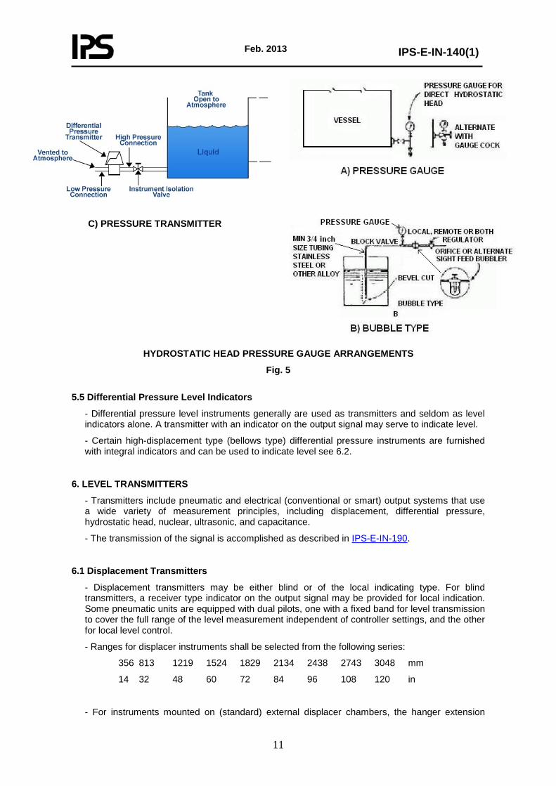
5.4 Hydrostatic Head Pressure Gauges
- Level indication by this means is limited to tanks or vessels not under pressure. The height of a liquid above a pressure gauge can be determined from the pressure gauge reading (hydrostatic head) provided the density of the Liquid is known. However, where specific gravity changes are large, this type of level indicator is highly inaccurate if read under one condition of calibration.
- Pressure gauge arrangements are illustrated in Fig. 5, view A in the Fig. shows the direct hydrostatic head type, and view B shows an air-bubbler system with either remote or local indication.
Feb. 2013
IPS-E-IN-140(1)
11
C) PRESSURE TRANSMITTER
HYDROSTATIC HEAD PRESSURE GAUGE ARRANGEMENTS
Fig. 5
5.5 Differential Pressure Level Indicators
- Differential pressure level instruments generally are used as transmitters and seldom as level indicators alone. A transmitter with an indicator on the output signal may serve to indicate level.
- Certain high-displacement type (bellows type) differential pressure instruments are furnished with integral indicators and can be used to indicate level see 6.2.
6. LEVEL TRANSMITTERS
- Transmitters include pneumatic and electrical (conventional or smart) output systems that use a wide variety of measurement principles, including displacement, differential pressure, hydrostatic head, nuclear, ultrasonic, and capacitance.
- The transmission of the signal is accomplished as described in IPS-E-IN-190.
6.1 Displacement Transmitters
- Displacement transmitters may be either blind or of the local indicating type. For blind transmitters, a receiver type indicator on the output signal may be provided for local indication. Some pneumatic units are equipped with dual pilots, one with a fixed band for level transmission to cover the full range of the level measurement independent of controller settings, and the other for local level control.
- Ranges for displacer instruments shall be selected from the following series:
356 813 1219 1524 1829 2134 2438 2743 3048 mm
14 32 48 60 72 84 96 108 120 in
- For instruments mounted on (standard) external displacer chambers, the hanger extension
Feb. 2013
IPS-E-IN-140(1)
12
length may be:
- 185 mm for rating ANSI class 150/300
- 215 mm for rating ANSI class 600
- 230 mm for rating ANSI class 900
- 255 mm for rating ANSI class 1500
- Because the displacer itself has relatively little motion, it should be used with caution. For example, highly viscous material can cling to the displacer and affect its calibration. When a displacement transmitter is used in such service, a liquid purge or heat tracing should be considered.
- Displacement transmitters sometimes are used for vacuum service or service with volatile liquids.
- Internal displacers should be avoided particularly on vessels that cannot be isolated without shutting down part of the plant.
- Where the signal is transmitted to a remote controller or panel-mounted instrument, the transmission should be accomplished as outlined in IPS-E-IN-190.
6.2 Differential Pressure Transmitters
See IPS-G-IN-210.
- Differential pressure transmitters have faster response characteristics than external cage displacement transmitters and require less range for stable control.
- Applications of displacement transmitters include remote control and remote indicating or recording of liquid level. This type of transmitter (usually the blind type) generally has an adjustable range and can have a high span elevation/ suppression capability. A receiver-type indicator on the output signal may be provided for local indication.
- Constant head may be maintained on the external or reference leg of the transmitter, because displacement of the measuring element with measurement changes is minimal even with condensable, no seal pot is required.
- A flange-connected, direct-tank mounted transmitter is used advantageously for measurement of slurries or viscous fluids. If required, the sensing diaphragm can be mounted flush with the inside of the vessel.
6.3 Hydrostatic-head Transmitters
- Hydrostatic head may be transmitted either by means of bubbler tube and pressure transmitter as shown in Fig. 6(A) or by means of diaphragm actuated air pilot transmitter mounted directly on the vessel as shown in Fig. 6(B).
- It should be pointed out that some makes of the diaphragm actuated pneumatic pilot are non-linear in the lower 20 percent of their range.

Feb. 2013
IPS-E-IN-140(1)
13
HYDROSTATIC HEAD LEVEL TRANSMITTERS
Fig. 6
6.4 Nuclear Type Level Transmitters
- Nuclear-type level instruments are used where other types of internal or external instruments cannot be used, such as cocking or vacuum towers.
- Nuclear level instruments measure with beta or gamma rays that are sensed by radiation detectors. A radioactive source is placed so that the vessel contents are between the source and the detector. When the vessel is empty the count rate is high and as the level rises, the count rate decreases.
- The strength of the radiation sensed by the detector depends on the density or thickness of the material in the vessel, the distance between the source and the detector, and the thickness of the vessel wall and insulation. The range is limited by the size of the source (factory selected for application). Multiple sources are used sometimes to measure wide ranges see Fig. 7.
- Additional information shall be obtained from the manufacturers.

Feb. 2013
IPS-E-IN-140(1)
14
TYPICAL ARRANGEMENT OF NUCLEAR LEVEL TRANSMITTER
Fig. 7
6.5 Ultrasonic-type Level Transmitters
- Ultrasonic-transmitters work on the principle of measurement of the time required for sound waves to travel through space. They are suitable for difficult level measurement applications of liquids and solids. (See Fig. 8).
- A sound transmitter (transducer) converts an electrical pulse to sound waves which reflect off the level surface being measured. The reflected signal is detected by either the same or another transducer.
Since the speed of sound through the medium above the level surface can be determined, round trip time from signal transmission to reception can be measured and is proportional to level.
- Other types of radiation such as radar, RF, laser may be considered.

Feb. 2013
IPS-E-IN-140(1)
15
TOP MOUNTED ULTRASONIC-TYPE LEVEL TRANSMITTER
Fig. 8
6.6 Capacitance-type Level Transmitters
- Capacitance level transmitters measure the changing electrical capacitance that occurs in the device as the level in the vessel being measured varies. (See Fig. 9).
- A capacitor consists of two conductive plates separated by an insulator. Its capacitance is a function of the area of the plates, the spacing between them, and the dielectric constant of the insulator.
- The capacitance level transmitter consists of a vertical probe that is inserted into the vessel in which the level is being measured.
The probe may either be plain or sheathed with an insulating material and serves as one of the plates of the capacitor.
If the vessel is an electrical conductor and the material (liquid or granular) being measured is an insulator, a plain bare probe normally is used. In this case the vessel serves as the other plate. Since the material being measured has a different dielectric constant than the air, vapor, or gas being displaced, the electrical capacitance between the probe and tank varies with level.
If the material being measured is an electrical conductor, an insulated probe is used the sheath serving as the dielectric and the material measured replacing the tank as the other plate. In this case, the size of the capacitor plate and therefore its capacity varies with level.
- With a capacitance/radio-frequency sensing element in an external cage, the difference in density due to temperature that results in a lower liquid level in the chamber is, to a large degree, offset by the higher dielectric constant of the denser liquid; hence, the indicated level will be close to the vessel’s liquid level.

Feb. 2013
IPS-E-IN-140(1)
16
CAPACITANCE-TYPE LEVEL TRANSMITTER
Fig. 9
7. LOCALLY MOUNTED CONTROLLERS
- Locally mounted controllers used on all pressure vessels include the displacement, caged ball-float, internal ball-float, and differential-pressure types.
- "Dual Pilot" displacement instruments provide local control as well as transmission when operated from a single displacer.
- Direct operated type level controls (ball float and mechanically linked valve) shall not be used.
- Internal ball-float controllers sometimes are used for asphaltic or waxy fluids, for coking service, or where the liquid contains particles or materials that tend to settle down and that would eventually block the float action in an external cage type instrument. On severe coking

Feb. 2013
IPS-E-IN-140(1)
17
applications, it may be desirable to use a steam or flushing oil purge to keep the shaft free and the packing in suitable condition. In such applications, it is preferable to use dip-tube, purge-type, or differential pressure-type level transmitters and controllers where possible.
- In severe services (the float will be subjected to turbulence within the vessel), it is recommended that the controller be supplemented by another type of instrument (for example, differential pressure or other special type).
- Differential pressure controllers may be in the form of a controller integrally mounted on a high-displacement type differential pressure unit. However, the most common use of differential pressure instruments in level control is to use a differential pressure transmitter with a separately mounted receiver controller.
8. REMOTE OR PANEL-MOUNTED RECEIVERS
- Receiver level instruments actuated by transmitted signals are often desired on control panels or other remote locations. These receivers may be either electronic or pneumatic. Remote receiver level instruments are normally indicating controllers or indicators only, although recorders are sometimes used for special applications. (See IPS-M-IN-150).
- The recommended scale or chart range for level instruments is 0 to 100 linear, representing a percentage of full scale.
- For signal transmission, see IPS-G-IN-190.
9. LEVEL SWITCHES
- Basic instruments for intiating high-level or low-level alarm signals are, with the possible exception of the float size, the same as those discussed in 6 and 7.
- Other types (For example, pressure switches at the receiver in pneumatic transmission systems, current or voltage switches in electronic transmission systems, hydrostatic-head-pressure-actuated switches on non pressurized tanks, and differential pressure actuated switches on pressurized vessels), sometimes are used. For a detailed discussion of alarms and protective devices, see IPS-G-IN- 260.
10. TANK LEVEL GAUGING
10.1 Traditional Methods of Tank Level Gauging
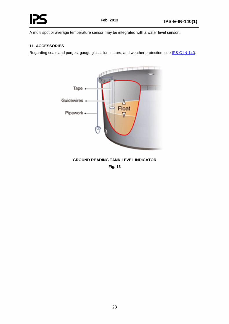
a) Float and cable tank level gauges are the most common means of indirect tank level indication. These gauges are used primarily on large storage tanks. see Fig. 14. Gauge boards (targets) are sometimes used for read out on small tanks or other noncritical applications, also it is called "Ground Reading Tank Level Indicator". See Fig. 13.
b) The reliability and continuing accuracy of a tank gauge installation is dependent directly upon the condition of the tank on which it is installed. Old and incorrectly erected tanks, particularly those with unstable bottoms, shells or roofs, will introduce appreciable amounts of error and variation that no gauge, however carefully installed, can correct.
c) Where maximum accuracy is required, a tank level gauging system should provide compensation for the variation of float immersion due to liquid specific gravity. High accuracy also may require powered floats or displacer to reduce immersion and hysteresis errors (servo or spring-operated automatic tank gauging).
d) Through use of a low-voltage servomotor or spring/measuring error induced by friction, are eliminated, while improving sensitivity and repeatability. See Fig. 10, which illustrates the typical parts of servomotor type of level gauging.

Feb. 2013
IPS-E-IN-140(1)
18
TYPICAL SERVO LEVEL GAUGE
Fig. 10
A: Displacer
K: Flexible Wire
B: Measuring Drum
C: Magnetic Coupling
D: Detection Plate
J: Balance Spring
E: Integration Circuit
F: Servomotor
G: Digital Counter
H: Transmitter (analog or digital)
I: Limit/Level/Alarm Switches

Feb. 2013
IPS-E-IN-140(1)
19
e) Where turbulence caused by high emptying and filling rates or by mechanical agitators can affect the float or sensing element, it is usually necessary to enclose the measuring element in a stilling well. These wells shall be installed in a perfectly vertical position. See Fig. 11 where high-viscosity materials are encountered, it may be desirable to provide heating for stilling well Liquefied Petroleum Gas (LPG) or other boiling surface services usually require a stilling well.
- Tank level gauges often are tied into a multiple tank remote read out. There are a number of-different proprietary or systems. These transmission systems usually are designed to minimize wire costs, and they usually include temperature transmission.
- Supervisory computers and micro processor-based read-out systems monitor tank fields. To provide an adequate scan cycle, a computerized tank level gauging system requires a rapid response from the tank gauge transmitter.
- High-or low-level alarms can be provided in four ways;
a) Separate float-type level switches mounted outside the tank.

Feb. 2013
IPS-E-IN-140(1)
20
TYPICAL ARRANGEMENT OF STILLING WELLS FOR TANK GAUGES
Fig. 11

Feb. 2013
IPS-E-IN-140(1)
21
b) Position detector sensing the floating roof.
c) Electrical switches mounted in the gauge head.
d) Continuous monitoring of tank levels with automatic comparison with an alarm setting.
The first three ways, require extra wiring from the tank to the control center. The first and second way will provide an alarm even if the tank gauge float or the gauging system fails.
- Some of the practices mentioned are outlined in MPMS Ch. 3 They cover installing and using automatic tank gauges and should be referred to for additional information.
- For more details regarding Automatic Tank Gauging see IPS-G-IN-300.
10.2 Hydrostatic Tank Gauging (HTG)
- Hydrostatic Tank Gauging (HTG) is a relatively new method for measuring the mass, volume, or level of the product in a tank by sensing the hydrostatic pressure-rather than the level.
- A typical HTG on an atmospheric tank consists of two precision pressure transmitters and a resistance temperature sensor (RTD).
A third pressure transmitter (P3) is used for pressurized tanks. One pressure transmitter (P1) is mounted on the tank shell just above the bottom. The second pressure transmitter (P2) is mounted above the P1. P1 measures the total hydrostatic pressure of the product. The difference between P1 and P2 pressure permits calculation of the fluid density at storage temperature. The temperature sensor permits calculation of standard density.
- Multiplying the bottom hydrostatic pressure by the tank area gives the product mass. Dividing the mass by the standard density gives the standard volume. Dividing the mass by the product density and the tank area gives the tank level see Fig. 12.
- The previous mentioned calculations are achieved by the microprocessor circuits in the HIU (hydrostatic interface unit) were the final breakthrough. The HIU is a field-mounted device that contains logic to calculate the product mass, density at product temperature, standard density, product volume, and standard product volume and level. It also has microprocessor memory for a set of tank capacity tables for each tank. Essentially perfect calculation accuracy is provided so that the total system accuracy is determined by the accuracy of the pressure transmitters. The HIU includes hardware and diagnostic routines and extensive alarm capabilities.
10.2.1 Corrections:
Some corrections may be considered as follows:
- The height of the P1 transmitter and the distance between P1 and P2 transmitters.
- Tank shell diameter and height expansion due to temperature.
- Tank shell diameter expansion from product hydrostatic pressure.
- API temperature/gravity conversion constants.
- Geographic variation of the earth’s gravity.
10.2.2 Advantages of HTG;
HTG offers the following advantages: bottom-up measurement, no moving parts, external tank mounting, density read out, mass read out, ease of maintenance and low installation costs. HTG uses a fundamentally different method of product measurement. Eliminates errors caused by bottom movement, encrustation, and tank calibration (strapping) affect. HTG, however, avoids many of the level measurement errors caused by top-down measurement, and measuring devices.

Feb. 2013
IPS-E-IN-140(1)
22
TANK HYDROSTATIC GAGING AND INVENTORY MANAGEMENT SYSTEM
Fig. 12
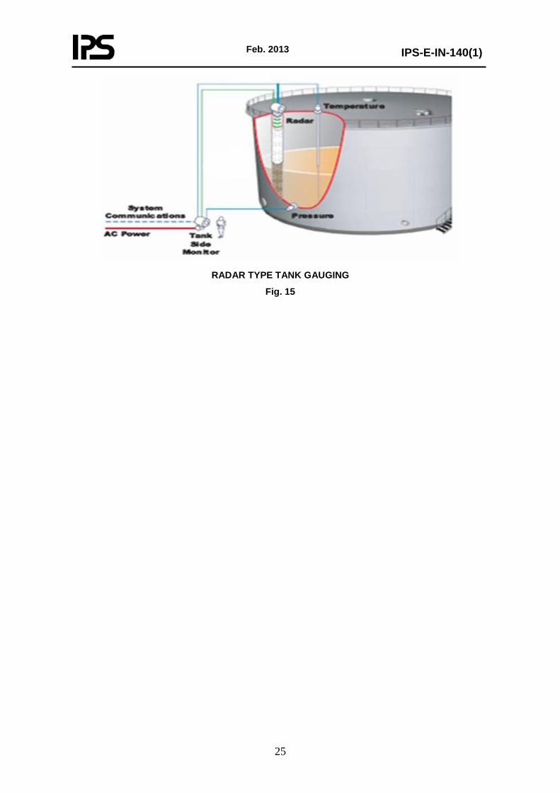
10.3 Radar Tank Gauging
Radar Tank gauging is designed for refineries, tank terminals and the petrochemical industry. It is the accurate system for custody transfer, process control, inventory control or for filling a tank without risk of overflow .The system includes products for level and temperature measurement. Radar gauge measurement is independent of the process conditions inside the tank. Temperature, pressure and gas vapors have minimal affect on “radar beams”.
10.3.1 Level transmitter
The Radar Level gauge is possible to use with a wide range of antennas for different applications. Radar tank gauges are "downward-looking" measuring system installed on the tank roof. They measure the distance from the reference point (process connection) to the product surface.
Currently there are two measurement techniques in common use for level measurement. They are frequency modulated continuous wave (FMCW) radar and PULSE radar.
Due to the nature of the microwave, radar tank gauges need to be equipped with functions to suppress interference echoes (e.g. from edges and weld seams) in the tank so they are not interpreted as level measurement. Radar technology is suitable for measuring a wide range of petroleum products.
10.3.2 Temperature sensor
For temperature compensation considering for tank volume calculation, a number of spot elements are placed at different heights to provide a tank temperature profile and an average temperature. Only fully immersed elements are used to determine product temperature.
Feb. 2013
IPS-E-IN-140(1)
23
A multi spot or average temperature sensor may be integrated with a water level sensor.
11. ACCESSORIES
Regarding seals and purges, gauge glass illuminators, and weather protection, see IPS-C-IN-140.
GROUND READING TANK LEVEL INDICATOR
Fig. 13

Feb. 2013
IPS-E-IN-140(1)
24
TRADITIONAL AUTOMATIC TANK GAGING
Fig. 14
Feb. 2013
IPS-E-IN-140(1)
25
RADAR TYPE TANK GAUGING
Fig. 15

Feb. 2013
IPS-E-IN-140(1)
26
APPENDICES
APPENDIX A
DATA SHEETS WITH THEIR FILLING INSTRUCTIONS GAUGE GLASSES AND
COCKS SHEET –––––––––– OF ––––––––––
SPEC. No. REV No. BY DATE REVISION CONTRACT DATE REQ. P.O. BY CHK’D APPR.
1. Gauge Column Cocks Assembled with Nipples Unassembled
GAUGE GLASSES 2. Type: Reflex Transparent Tubular Large Chamber Weld Pad 3. Conn.: Size and Type____________________________ Top & Bot. Side Back Vent__________Drain _____________________ 4. Material _____________________________________ 5. Rating ___________ 6. Options: Illuminator Illuminator Housing Material __________________ Power Voltage / Consumption ________________ Cable Entry / Connection ____________________ Enclosure Protection ________________________ Area Classification __________________________ Internal Tube External Jkt Non-Frost Ext. Length __________________ Calb. Scale Protective Coating Mica Shield Other ____________________________________ 7. Manufacturer __________________________
GAUGE COCKS
8. Type: Offset Straight 9. Conn.: Vessel _____ Gauge ____Vent/Drain____________ 10. Material: Body ________Trim ______________________ 11. Rating: ________ 12. Construction: _________________________________ 13. Type of Conn.: Vessel ____________________________ Gauge ___________________________ 14. Bonnet _______________________________________ 15. Options: Ball Checks Renewable Seats Other _________________________________ 16. Manufacturer & Model_____________________________
Item Rev. Tag No. Visible Length
Sections required Number/Length
Conn. Length
Gauge Model No.
Operating Fluid
Vessel Tag
Number Notes
Press. Temp.
Notes:
IPS-FORM E-IN-140.1

Feb. 2013
IPS-E-IN-140(1)
27
GAUGE GLASSES AND COCKS
Instructions for IPS Form E-IN-140.1
1. Check what is to be supplied, and whether assembled or unassembled.
2. Select one type only per sheet.
3. Specify size, style and location of process connections. If side or back connections are used, vent and drain connections are available.
4. Material of gauge glass chamber and connections.
5. Specify rating. It is assumed that a higher rating is also acceptable. For example ANSI Class 300.
6. This section is used only if the option applies to all items listed on the sheet. Where options apply to certain items only, use the notes column instead.
7. Use for Manufacturer and Series or Type; detailed number may be listed in the tabulation.
8. Select style of cock, if used.
9. Show connection sizes only.
10. Write in body and trim materials.
11. See line 5 above.
12. Specify action and type of handle; plain closing or quick closing, handwheel or lever handle. This may be covered by the Model No. given on Line 16.
13. Specify type of connection on each side; plain union, spherical union, solid shank. Give flange size, rating and type, if applicable.
14. Bonnet may be screwed, union type, or bolted.
15. Options checked here apply to all items. See line 6 above. Include special packing.
16. Fill in if required, or as a final record after selection is made.
"Conn. Length" in tabulation refers to distance between center lines of vessel connections.

Feb. 2013
IPS-E-IN-140(1)
28
1 Tag Number
2 Service 3 Line No./Vessel No.
BODY/CAGE
4 Body Or Cage Mtl Rating 5 Conn Size & Location Upper Type 6 Conn Size & Location Lower Type 7 Case Mounting Type 8 Rotatable Head 9
10 Orientation 11 Cooling Extension 12
DISPLACER OR FLOAT
13 Dimensions 14 Insertion Depth 15 Displacer Extension 16 Disp. or Float Material 17 Displacer Spring Tube Mtl 18 19
XMTR/CONT
20 Function 21 Output 22 Control Modes 23 Differential 24 Output Action. Level Rise 25 Mounting 26 Mounting 27 Elec. Power or Air Supply 28 Calibration Span
SERVICE
29 Upper Liquid 30 Lower Liquid 31 Sp. gr.: Upper Lower 32 Press. Max. Normal 33 Temp. Max. Normal 34 35
OPTIONS
36 Airset Supply Gauge 37 Gauge Glass Connections 38 Gauge Glass Model No. 39 Contacts: No. Form 40 Contact Rating 41 Action of Contacts 42 43 44 45
46 Manufacturer 47 Model Number 48
Notes:
IPS-FORM E-IN-140.2
LEVEL INSTRUMENTS (DISPLACER or FLOAT)
SHEET ––––––––– OF ––––––––––
SPEC. NO. REV No. BY DATE REVISION
CONTRACT DATE
REQ. P.O. BY CHK’D APPR.

Feb. 2013
IPS-E-IN-140(1)
29
LEVEL INSTRUMENTS
(DISPLACER OR FLOAT)
Instructions for IPS Form E-IN-140.2
1. Tag No. or other identification.
2. Process service.
3. Line number or vessel number on which cage or body is installed.
4. Material of chamber and/or mounting flange.
5. For float specify top or side of vessel connection. For displacer in a chamber specify upper, then lower connection; such as side-side, side-bottom, top-bottom, etc. Give flange size and rating or NPT size.
6. Same as 5.
7. Refers to position of case when viewing the front of the case relative to the chamber; the case is either to the left, right, or top.
8. On displacer instruments specify if case is to be rotatable with respect to the chamber. This only applies if there is one or more side connections.
10. Orientation of control with respect to displacer cage.
11. Cooling Extension.
13. Specify float diameter or displacer length. The displacer length is also the range.
14. Insertion depth applied to ball floats. It is the mounting flange to the center of the ball.
15. The displacer extension is measured from the face of the mounting flange to the top of the displacer. This dimension is required only for top of vessel mounted instruments.
16. Includes rod.
17. Refer to MFR’s standard materials or special materials.
18.
19.
20. Transmitter, controller, switch, etc.
21. Air pressure or electrical signal output of transmitter or controller.
22. P: Proportional
Pn: Narrow band proportional
Pi: Proportional plus Integral (Reset).
23. Differential if controller on/off must specify differential adj. or fixed State adjustable range or fixed amount.
24. INCREASE (Direct action) or DECREASE (Reverse Action).
25. Remote or integral.
26. Electrical classification of housing NEMA number.
27. Air pressure or voltage. If electronic, state whether ac or dc.
28. Calibration span to be written.
29. Used only for interface application.
30. Used for all services.
31. Specific gravities at operating temperature.
32. Operating and max. pressure or vacuum.

Feb. 2013
IPS-E-IN-140(1)
30
33. For cryogenic service, give minimum temperature.
34.
35.
36. Airset assumed mounted to case.
37. Connections on chamber, give size.
38. Specify gauge glass, if required.
39. Contact form: SPST, SPDT, etc.
40. Give volts, Amps.
41. Describe contact action with level.
42.
43.
44.
45.
46. Manufacturer.
47. Model number.

Feb. 2013
IPS-E-IN-140(1)
31
1 Tag Number Service
GENERAL
2 Function Record Indicate Control Blind Trans Integ Other –––––––– 3 Case MFR STD Nom Size ––––––––––––––– Color: MFR STD Other –––––––––– 4 Mounting Flush Surface Yoke Other –––––––––––––––––––––––––––––––––––– 5 Enclosure Class General Purpose Weather Proof Explosion Proof Class ––––––––––––– For use in Intrinsically Safe System Other –––––––––––––––––––––––––––––––
6 Power Supply 117V 60 Hz Other ac –––––––– dc ––––––– Volts –––––––––––––––––––––– 7 Chart 12 in. Circ. Other –––––––––– Range –––––––––– No. –––––––––––––––––––– 8 Chart Drive 24 hr Other –––––––––––– Elec. Spring Other –––––––––––––––––––––––– 9 Scale Type –––––––––––– Range: 1 ––––––– 2 –––––––– 3 –––––––––––––––––––––––––
XMTR 10 Transmitter 4–20 mA 10-50 mA 21-103 kpa (3-15 psig) Other ––––––––––––––––––
Output For Receiver, See Spec Sheet ––––––––––––––––––––––––––––––––––––––––––––
CONTROLLER
11 Control Modes P = Prop (Gain), I = Integral (Auto Reset), D = Derivative (Rate) Sub: s = Slow, f = Fast If Df P PI PD PID Is Ds
Other –––––––––––––––––––––––––––––––––––––––––––––––––––––––––––––––
12 Action On Meas. Increase Output: Increase Decrease –––––––––––––––––––––––––
13 Auto Man Switch None MFR STD Other –––––––––––––––––––––––––––––––––––––––––––
14 Set Point Adj. Manual External Remote Other ––––––––––––––––––––––––––––––––
15 Manual Reg. None MFR STD Other –––––––––––––––––––––––––––––––––––––––––––
16 Output 4-20 mA 10-50 mA 21-103 kpa (3-15 psig) Other ––––––––––––––––––
UNIT
17 Service Flow Level Diff. Pressure Other –––––––––––––––––––––––––––––––– 78 Element Type Diaphragm Bellows Mercury Other –––––––––––––––––––––––––––––– 19 Material Body –––––––––––––––––––––––––––––––– Element –––––––––––––––––––––––– 20 Rating Over range –––––––––––––––––– Body Rating –––––––––– Psig 21 Diff. Range Fixed Adj. Range –––––––––––––––––––– Set At ––––––––––––––––––––––––– 22 Elevation ––––––––––––––––––––––––– Suppression –––––––––––––––––––––––– 23 Process Data Fluid –––––––––––– Max Temp. ––––––––––––––– Max Press. ––––––––––––––––– 24 Process Conn. ½ in. NPT Other –––––––––––––––––––––––––––––––––––––––––––––––––––
25 Alarm Switches Quantity ––––––––––––– From ––––––––––– Rating –––––––––––––––––––––––––
26 Function Meas. Var. Deviation Contacts To ––––––––––––– on Inc. Meas.
27 Options Pressure Element Range –––––––––––––––– Material –––––––––––––––––––– Temp. Element Range ––––––––––––––––– Type –––––––––––––––––––––––– –––––––––––––––––––––––––––––––––––––––––––––––––––––––––––––––––––– Filt Reg. Sup. Gauge Output Gauge –––––––––––––––– Charts Valve Manifold –––––––––––––––––––––––––––––––––––––––––––––––––––––––– Cond. Pots Adj. Damp Integral Sq. Rt. Ext. Integral –––––––––––––––––––––––––––––––––––––––––––––––––––––––––––––– Other –––––––––––––––––––––––––––––––––––––––––––––––––––––––––––––––
28 MFR & Model No. –––––––––––––––––––––––––––––––––––––––––––––––––––––––––––––––––––– Notes:
DIFFERENTIAL PRESSURE INSTRUMENTS
SHEET –––––––––– OF –––––––––
SPEC. NO. REV No. BY DATE REVISION
CONTRACT DATE
REQ. P.O. BY CHK’D APPR.

Feb. 2013
IPS-E-IN-140(1)
32
Rev. Tag Adj. Range Set Range
Scale or Chart
Scale Factor Service Notes
Notes:
DIFFERENTIAL PRESSURE INSTRUMENTS
SHEET––––––––––– OF–––––––––
SPEC. NO. REV No. BY DATE REVISION
CONTRACT DATE
REQ. P.O. BY CHK’D APPR.

Feb. 2013
IPS-E-IN-140(1)
33
DIFFERENTIAL PRESSURE INSTRUMENTS
Instructions for IPS Forms E-IN-140 3a & 3b
1. To be used for a single item. Use secondary sheet for multiple listing.
2. Check as many as apply.
3. Nominal size refers to approximate front of case dimensions; Width × height.
4. Yoke refers to a bracket designed for mounting the instrument on a pipe stand.
5. Enclosure class refers to composite instrument. If electrical contacts are in the case they must meet this classification inherently or by reasons of the enclosure. Use NEMA identification system or ISA identification RP 8.1.
6. Specify electrical power to the entire instrument from an external source.
7. Specify chart size, range and number if applicable.
8. "24 hr" is the time for one rotation of the chart. Other speeds should be listed in hours or days. If a spring wound clock is used fill in number of hours or days it runs between windings.
9. The scale type may be SEGMENTAL, ECCENTRIC, or DIAL (CIRCULAR). Space is provided for multiple ranges on the same scale.
10. Specify transmitter output if applicable.
11. See explanation of terminology given on specification sheet. For further definition refer to American National Standard C85-1-1963 "Terminology for Automatic Control". Specific ranges of control modes can be listed after "OTHER", if required.
12. For multiple items specify on second sheet.
13. If standard auto-manual switching is not known or not adequate, specify number of positions.
14. Remote set point adjustment assumes full adjustment range. Specify limits if required.
15. Specify if applicable.
16. Specify if applicable.
17. Specify measure variable.
18. Specify type of element or write in "MFR. STD".
19. Materials refer to wetted parts only.
20. Over-range protection refers to maximum differential pressure. The instrument can withstand without a shift in calibration.
21. Adjustable range means that the range can be changed without replacing any parts.
22. Elevation
23. Give process data affecting meter selection. Flow elements such as orifice plates are specified on separate forms.
24. Refers to connections piped to process equipment or pipe line. Special flanged connections and extended diaphragms for level applications should be described after "OTHER".
25. Form may be SPST, DPDT, or others. Rating refers to electrical rating of switch or contacts in Amps.
26. Specify if alarm is actuated by measured variable or by deviation from controller set point. Give contact action if single throw form.
27. Specify required accessories. If temperature element is used, the second line is provided to specify well, length of capillary tubing and other details of the thermal system.
28. After selection is made fill in manufacturer and specific model number.

Feb. 2013
IPS-E-IN-140(1)
34
SECONDARY SHEET- for listing multiple instruments. List all instruments of the same type specified on the primary sheet, with variations as shown. "Notes" refers to notes listed by number at the bottom of the sheet.

Feb. 2013
IPS-E-IN-140(1)
35
GENERAL
1 Tag Number 2 Service 3 Line No. Vessel No. 4 Application 5 Function 6 Fail-Safe 7
PROCESS CONDITIONS
8 Upper Fluid 9 Upper Fluid Dielectrical Connection
10 Lower Fluid 11 Lower Fluid Dielectrical Connection 12 Max. Pressure Oper. Pressure 13 Max. Temperature Oper. Temperature 14 Moisture 15 Vibration 16 Material Build – Up 17
PROBE
18 Model No. 19 Orientation 20 Style 21 Material 22 Sheath 23 Insertion Length 24 Inactive Length 25 Gland Size Gland Material 26 Conduit Size & Connection 27
AMLIFIER
28 Location 29 Enclosure 30 Power Supply 31 Conduit Size & Connection 32
SWITCH
33 Type 34 Quantity Form 35 Rating 36 Load Type 37 Contacts Open on Level 38
TRANSMITTER
39 Output 40 Power Supply 41 Enclosure 42 Range 43
OPTIONS 44 Compensation Cable 45 Local Indicator 46
PURCHASE
48 Manufacturer 49 Model 50 Purchase Order Number 51 Price Item Number 52 Serial Number
Notes:
LEVEL INSTRUMENTS CAPACITANCE SHEET––––––––––– OF–––––––––
SPEC. NO. REV No. BY DATE REVISION
CONTRACT DATE
REQ. P.O.
BY CHK’D APPR.

Feb. 2013
IPS-E-IN-140(1)
36
LEVEL INSTRUMENTS, CAPACITANCE TYPE
Specification Sheet Instructions for IPS Form E-IN-140.4 Prefix number designates line number on corresponding Specification Sheet.
1. Enter the capacitance level instrument tag number from the P&ID.
2. Enter a narrative description of the process service in which the capacitance level instrument is installed. Example; P-101 Stripper Bottoms
3. Enter the process line number from the P&ID (if applicable). Enter the vessel number on which the capacitance level instrument is attached.
4. Denote the type of application that the capacitance level instrument will be used in, such as solids level, interface detection or liquid level, etc.
5. Enter the capacitance level instrument's function. The instrument’s function can either be Control or Indication which is determined from the control function shown on the P&ID.
6. Specify the direction the capacitance level instrument’s output should move if the instrument should fail, such as high, low or none.
7. Blank: Modify the data sheet to display the “Area Classification” instead of Blank in Line 7: then enter the Area Classification where the instrument is located in the field. Consult with the project electrical engineer for area classification. Example: Class 1, Div. 2, Group C&D (Group B if Hydrogen is present).
8. Applicable only for interface level measurements. If applicable, enter the type of fluid in the pipe or vessel to which the capacitance level instrument is attached, such as gasoline, water, hydrocarbon condensate, etc.
9. (Check the data sheet for the correct heading, earlier version my have “Upper Fluid Dielectrical Connection”. If this is the case, then have the SPI Administrator make the change in the data sheet to reflect Upper Fluid Dielectric Constant.) Applicable only for interface level measurements. Fluid dielectric constant should be provided by the Process Engineer in the SPI process data module.
10. Applicable for all level measurements. Enter the type of fluid in the pipe or vessel to which the capacitance level instrument is attached, such as gasoline, water, hydrocarbon condensate, etc.
11. (Check the data sheet for the correct heading, earlier version my have “Lower Fluid Dielectrical Connection”. If this is the case, then have the SPI Administrator make the change in the data sheet to reflect Lower Fluid Dielectric Constant.) Applicable for all level measurements. Enter the type of fluid in the pipe or vessel to which the capacitance level instrument is attached, such as gasoline, water, hydrocarbon condensate, etc.
12. The maximum and operating pressures at which the fluid in the pipe or vessel operates. Operating pressures are provided by the Process Engineer in the SPI process data module or can be found on the P&ID under the Vessel Information as Design Pressure.
13. The maximum and operating temperatures at which the fluid in the pipe or vessel operates. Operating temperatures are provided by the Process Engineer in the SPI process data module or on the P&ID under the Vessel Information as Design Temperature.
14. Applicable only for solids level measurement. Denote the percentage of moisture in the content of the solids that the capacitance level instrument will be measuring.
15. Denote whether or not the capacitance level instrument will experience any vibration in this application.
16. Denote whether or not if there is a potential for material to accumulate on the capacitance level instrument sensor.
17. Blank.
18. Specify the model number of the capacitance level instrument probe from the manufacturer's catalog or as provided in the vendor’s quotation.

Feb. 2013
IPS-E-IN-140(1)
37
19. Specify the orientation of the capacitance level instrument probe when installed on the vessel or pipe, such as horizontal or vertical.
20. Specify the style of the capacitance level instrument probe, such as general purpose, heavy duty, concentric shield, etc.
21. Enter the capacitance level instrument probe material. Normally this material should be compatible with the plant environment. Consult the manufacturer’s catalog for available materials including compatibility to the process maximum pressure and temperature.
22. If a sheath is required, specify the sheath thickness as well as the sheath material. Normally this material should be compatible with the plant environment. Consult the manufacturer’s catalog for available materials including compatibility to the process maximum pressure and temperature.
23. Specify the expected total immersion of the capacitance level instrument probe in the process fluid.
24. Specify the inactive extension of the capacitance level instrument probe above the process fluid.
25. Specify the capacitance level instrument’s sealing gland size and material of construction.
26. Enter the electrical connection size and type. Electrical connections are normally 1/2” NPT for electrical conduit entry. Consult manufacturer's catalog for available connection sizes and compliance with the design installation details.
27. Modify the data sheet to display the “Process Connection” instead of Blank in Line 27: then enter the size, type and connection rating for the Process Connection. I applicable, include the process connection flange material. Example: 2”, 150#RF, SS.
28. Denote if the capacitance level instrument’s electronics are integral to the probe or remotely mounted.
29. Enter the NEMA rating of the capacitance level instrument’s amplifier housing.
30. Denote the voltage level that the capacitance level instrument amplifier uses, such as 24 VDC loop or external power, 120 VAC, 60 Hz, 1-phase.
31. Enter the electrical connection size and type. Electrical connections are normally 1/2” NPT for electrical conduit entry. Consult manufacturer's catalog for available connection sizes and compliance with the design installation details.
32. Blank.
33. Denote the type of switch contact, such as mercury, snap, etc.
34. Denote the number of switch contacts within the switch housing and denote the contact form, such as SPST, SPDT, etc.
35. Denote the switch contact rating in voltage and amperes.
36. Denote the contact load type, such as inductive or non-inductive.
37. Denote the action of the switch contacts, i.e. on rising liquid level the contacts open or close. Denote the cause of the actuation, such as low liquid level, high liquid level, etc.
38. Blank.
39. Denote the type of signal output the capacitance level instrument’s transmitter will provide such as 4 – 20 mA.
40. Denote the voltage level that the capacitance level instrument transmitter uses, such as 24 VDC loop or external power, 120 VAC, 60 Hz, 1-phase.
41. Enter the NEMA rating of the capacitance level instrument’s transmitter housing.
42. Enter the vessel fluid range that the capacitance level instrument transmitter will need to measure. This range is selected to cover the level points as noted on the P&ID by the Process Engineer. Consult with the project Process Engineer for vessel fluid range if not denoted on the P&ID.
Feb. 2013
IPS-E-IN-140(1)
38
43. Blank.
44. If required, specify the length of special compensation cable to be furnished with the capacitance level instrument’s probe.
45. Denote whether or not a local indicator is to be included in the capacitance level instrument’s transmitter housing. Specify a display calibration range which is typically the transmitter calibrated range.
46. Blank.
47. Blank.
48. Enter the name of the capacitance level instrument manufacturer.
49. Specify the model number of the capacitance level instrument from the manufacturer's catalog or as provided in the vendor’s quotation.
50. Enter the purchase order number for the capacitance level instrument.
51. Do not fill in the price field. Prices will be shown on the purchase order. Enter the purchase order item number for the capacitance level instrument.
52. Do not fill in the serial number. This can be filled in later by Plant Maintenance if required.
Notes:
Include any explanatory notes for the manufacturer here.
As a minimum specify the following:
1. Any special tagging requirements.
2. Denote the P&ID number on which the capacitance level instrument is located.
3. Denote the electrical area classification where the capacitance level instrument is located in the field.
4. Denote the ambient temperature range from the process site conditions document.
5. Enter the vessel trim number along with the vessel material of construction.
6. Denote the required flange finish if the capacitance level instrument’s connections are to be flanged.
7. Denote whether the displacer level instrument has any special type of material requirements, such as PMI, NACE, etc.

Feb. 2013
IPS-E-IN-140(1)
39
GENERAL
1 Tag Number 2 TYPE 3 4 Service
BODY
5 Material 6 Top Conn. Location 7 Bottom Conn. Location 8 Conn. Size & Rating 9 Gauge Glass Conn
10 Type Glass 11 Type of Gauge Cock 12 Try Cocks 13 Whistle
FLOAT OR DISPLACER
14 Dimensions 15 Length Rod Arm 16 Material
SWITCH
17 Type 18 Quantity Form 19 Enclosure 20 Conduit Conn: Size & Type 21 Rating: Volts CY or D.C. 22 Amps Watts HP-KW 23 Load Type 24 Diff: Fixed Adjust 25 Adjustment: Int Ext.
26 Contacts Open Close
On Level
Incr. Decr.
27
SERVICE CONDITIONS
28 Upper Fluid 29 LOWER FLUID 30 SP. GR. Upper Lower 31 Minimum SP. GR. Diff. 32 Press: Oper. Max. 33 Temp: Oper. Max.
34 Manufacturers Model No.
Notes:
IPS-FORM E-IN-140.5
LEVEL SWITCHS
(FLOAT AND DISPLACEMENT TYPE)
SPECIFICATION SHEET
INSTRUMENT SPECIFICATIONS SHEET––––––––––– OF–––––––––
SPEC. NO. REV No. BY DATE REVISION
CONTRACT DATE
REQ. P.O. BY CHK’D APPR.
Feb. 2013
IPS-E-IN-140(1)
40
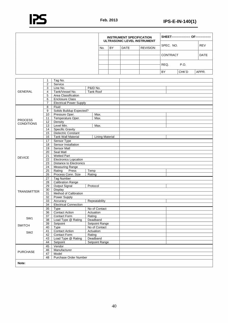
GENERAL
1 Tag No. 2 Service 3 Line No. P&ID No. 4 Tank/Vessel No. Tank Roof 5 Area Classification 6 Enclosure Class 7 Electrical Power Supply
PROCESS CONDITIONS
8 Fluid 9 Solids Buildup Expected?
10 Pressure Oper. Max. 11 Temperature Oper. Max. 12 Density 13 Level Min. Max. 14 Specific Gravity 15 Dielectric Constant 16 Tank Wall Material Lining Material
DEVICE
17 Sensor Type 18 Sensor Installation 19 Sensor Matl 20 Seal Matl 21 Wetted Part 22 Electronics Lopcation 23 Distance to Electronics 24 Measuring Range 25 Rating Press Temp 26 Process Conn. Size Rating
TRANSMITTER
27 Tag Number 28 Calibration Range 29 Output Signal Protocol 30 Display 31 Method of Calibration 32 Power Supply 33 Accuracy Repeatability 34 Electrical Connection
SW1 SWITCH
SW2
35 Type No of Contact 36 Contact Action Actuation 37 Contact Form Rating 38 Load Type @ Rating Deadband 39 Setpoint Setpoint Range 40 Type No of Contact 41 Contact Action Actuation 42 Contact Form Rating 43 Load Type @ Rating Deadband 44 Setpoint Setpoint Range
PURCHASE
45 Vendor 46 Manufacturer 47 Model 48 Purchase Order Number
Note:
INSTRUMENT SPECIFICATION ULTRASONIC LEVEL INSTRUMENT
SHEET––––––––––– OF–––––––––
SPEC. NO. REV No. BY DATE REVISION
CONTRACT DATE
REQ. P.O. BY CHK’D APPR.

Feb. 2013
IPS-E-IN-140(1)
41
ULTRASONIC LEVEL INSTRUMENT
Following are instructions for completion of the SPI Instrument Specification for Ultrasonic Level Instrumentation. Required reference documents are P&ID's, Piping Line Class Specifications and Ultrasonic Level Instrument Manufacturer's catalog.
1. Enter the ultrasonic level instrument tag number from the P&ID.
2. Enter a narrative description of the process service in which the ultrasonic level instrument is installed. Example; P-101 Stripper Bottoms
3. Enter the process line number from the P&ID (if applicable). Insert the P&ID number on which the ultrasonic level instrument is located.
4. Enter the vessel number on which the ultrasonic level instrument is attached. If the ultrasonic level instrument is installed on a tank, denote the type of roof, such as conical, flat, etc.
5. Enter the electrical area classification where the ultrasonic level instrument is located in the field. Consult with the project Electrical Engineer for Area Classification. Generally, Class 1, Division 2, Groups C & D. (Group B if Hydrogen is present.)
6. Enter the NEMA rating of the ultrasonic level instrument transmitter housing.
7. Denote the ultrasonic level instrument transmitter voltage level, such as 24 VDC loop or external power, 120 VAC, etc.
8. Enter the type of fluid in the vessel to which the ultrasonic level instrument is attached, such as gasoline, water, hydrocarbon condensate, etc.
9. Denote whether or not if there is a potential for solids to build up on the ultrasonic level instrument sensor.
10. The maximum and operating pressures at which the fluid in the pipe or vessel operates. Operating pressures are provided by the Process Engineer in the SPI process data module or can be found on the Piping Line List.
11. The maximum and operating temperatures at which the fluid in the pipe or vessel operates. Operating temperatures are provided by the Process Engineer in the SPI process data module or the Piping Line List.
12. Fluid density should be provided by the Process Engineer in the SPI process data module.
13. The minimum and maximum operating fluid liquid levels at which the ultrasonic level instrument will be required to measure. Minimum and maximum operating fluid levels are provided by the Process Engineer.
14. Fluid specific gravity should be provided by the Process Engineer in the SPI process data module.
15. Fluid dielectric constant should be provided by the Process Engineer in the SPI process data module.
16. Enter the material of the tank wall on which the ultrasonic level instrument is attached. If the tank has a liner, enter the material of the tank liner.
17. Denote the type of sensor used, such as non-contact ultrasonic.
18. Denote where the sensor is to be installed. Typically this will be the tank roof.
19. Enter the ultrasonic level instrument sensor material. Normally this material should be compatible with the plant environment. Consult the manufacturer’s catalog for available materials including compatibility to the process maximum pressure and temperature.
20. Enter the ultrasonic level instrument seal material. Normally this material should be compatible with the plant environment. Consult the manufacturer’s catalog for available materials including compatibility to the process maximum pressure and temperature.
Feb. 2013
IPS-E-IN-140(1)
42
21. Enter the ultrasonic level instrument wetted parts material. Normally this material should be compatible with the plant environment. Consult the manufacturer’s catalog for available materials including compatibility to the process maximum pressure and temperature.
22. Denote whether the ultrasonic level instrument transmitter housing will be integral to the sensor or remote mounted from the sensor.
23. If the ultrasonic level instrument transmitter will be remote mounted from the sensor, denote the distance from the ultrasonic level instrument sensor to the transmitter.
24. Enter the total possible measuring range of the ultrasonic level instrument sensor. Consult the manufacturer’s catalog for ultrasonic level instrument capabilities.
25. Enter ultrasonic level instrument pressure and temperature ratings as provided by the manufacturer.
26. Enter the size for the process connection on the ultrasonic level instrument. Enter the connection rating for the ultrasonic level instrument process connection.
27. Enter the ultrasonic level instrument transmitter tag number from the P&ID. Typically, this is the same tag number from Line 1.
28. Enter the vessel fluid range that the ultrasonic level instrument transmitter will need to measure. This range is selected to cover the level points as noted on the P&ID by the Process Engineer. Consult with the project Process Engineer for vessel fluid range if not denoted on the P&ID.
29. Denote the type of signal output the transmitter will provide such as 4 – 20 mA and the type of protocol used to communicate, such as HART or Foundation Fieldbus.
30. Denote whether or not a display is to be included in the ultrasonic level instrument transmitter housing. Specify a display calibration range which is typically the transmitter calibrated range.
31. Denote how the transmitter is to be calibrated by the vendor.
32. Denote the voltage level that the ultrasonic level instrument transmitter uses, such as 24 VDC loop or external power, 120 VAC, etc.
33. Enter the transmitter accuracy and repeatability as noted in the manufacturer’s catalog.
34. Enter the electrical connection size and type. Electrical connections are normally 1/2” NPT for electrical conduit entry. Consult manufacturer's catalog for available connection sizes and compliance with the design installation details.
35. Denote the type of switch contact, such as mercury, snap, etc. and denote the number of switch contacts within the switch housing.
36. Denote the action of the switch contacts, i.e. on rising liquid level the contacts open or close. Denote the cause of the actuation, such as low liquid level, high liquid level, etc.
37. Denote the switch contact form, such as SPST, SPDT, etc. Denote the switch contact rating in voltage and amperes.
38. Denote the switch contact load type, such as inductive or non-inductive, and denote if the switch deadband is adjustable or fixed.
39. Denote the setpoint at which the switch is to actuate and specify a setpoint range within which the setpoint maybe established or within which the setpoint is allowed to occur.
40. Denote the type of switch contact, such as mercury, snap, etc. and denote the number of switch contacts within the switch housing.
41. Denote the action of the switch contacts, i.e. on rising liquid level the contacts open or close. Denote the cause of the actuation, such as low liquid level, high liquid level, etc.
42. Denote the switch contact form, such as SPST, SPDT, etc. Denote the switch contact rating in voltage and amperes.
43. Denote the switch contact load type, such as inductive or non-inductive, and denote if the switch deadband is adjustable or fixed.
Feb. 2013
IPS-E-IN-140(1)
43
44. Denote the setpoint at which the switch is to actuate and specify a setpoint range within which the setpoint maybe established or within which the setpoint is allowed to occur.
45. Enter the name of the vendor who sold the ultrasonic level instrument.
46. Enter the name of the ultrasonic level instrument manufacturer.
47. Specify the model number of the ultrasonic level instrument from the manufacturer's catalog or as provided in the vendor’s quotation.
48. Enter the purchase order number for the ultrasonic level instrument.
Notes:
Include any explanatory notes for the manufacturer here.
As a minimum specify the following:
1. Any special tagging requirements.
2. Denote the ambient temperature range from the process site conditions document.
3. Enter the vessel trim number along with the vessel material of construction.
4. Denote the required flange finish if the ultrasonic level instrument’s connections are to be flanged.

Feb. 2013
IPS-E-IN-140(1)
44
GENERAL
1 Tag No. 2 Service 3 Application 4 Vessel Number Line Number 5 Vessel Int. Diameter Vessel Length 6 Line Size Line Schedule 7 Vessel Material Line material 8 Area Classification 9 Ambient Temperature
10 P&ID Number 11 Vessel Orientation Type
PROCESS CONDITIONS
12 Fluid Name 13 Specific Gravity 14 Viscosity 15 Temperature Oper. Max. 16 Pressure Oper. Max. 17 Max. Liquid Level (Tank Bot.=0) 18 Min. Liquid Level (Tank Bot.=0)
RADAR GAUGE SYSTEM
19 Model 20 Measurement Principle 21 Signal Processing Oper. Frequency 22 Measurement Range 23 Accuracy 24 Ingress Protection – IEC Certificate 25 Elect. Protection
ANTENNA
26 Type 27 Function 28 Stem Length Diameter 29 Process Connection 30 Mounting Position Mounting Location 31 Mounting Type 32 Distance (Adapter Plate to Tank Bot) 33 Material
ANTENNA UNIT
34 Function 35 Output 36 Mounting Location 37 Cable to Control Unit
CONTROL UNIT
38 Function 39 Local Display Programming Access 40 Output 41 Power Supply 42 Mounting Location
OPTION 43 Special Painting 44 Installation Kit 45 Cable (Antenna Unit to Control Unit)
PURCHASE
46 Vendor Price 47 Manufacturer 48 Model 49 Purchase Order Number 50 Serial Number
Note:
RADAR LEVEL SHEET––––––––––– OF–––––––––
SPEC. NO. REV No. BY DATE REVISION
CONTRACT DATE
REQ. P.O. BY CHK’D APPR.

Feb. 2013
IPS-E-IN-140(1)
45
RADAR LEVEL
Following are instructions for completion of the SPI Instrument Specification for radar level instruments. Required reference documents are P&ID’s, Piping Line Class Specifications and radar level instrument Manufacturer's catalog.
1. Enter the radar level instrument tag number from the P&ID.
2. Enter a narrative description of the process service in which the radar level instrument is installed. Example; P-101 Stripper Bottoms
3. Denote the type of application that the radar level instrument will be used in, such as solids level, liquid level, etc.
4. Enter the vessel number on which the radar level instrument is attached. Enter the process line number from the P&ID (if applicable).
5. Enter the interior diameter and length of the vessel on which the radar level instrument is attached.
6. If applicable, enter the process line size from the P&ID and the pipe schedule. Common examples are the use of stilling wells and stands pipes or level bridles used for mounting of radar gage.
7. Line material of the stilling well or stand pipe.
8. Enter the electrical area classification where the radar level instrument is located in the field. Consult with the project Electrical Engineer for Area Classification. Generally, Class 1, Division 2, Groups C & D. (Group B if Hydrogen is present.)
9. Denote the ambient temperature range from the process site conditions document.
10. Insert the P&ID number on which the radar level instrument is located.
11. Denote the orientation of the vessel, such as horizontal or vertical and denote the type of vessel on which the radar level instrument is mounted, such as ASME, conical roof, etc.
12. Enter the type of fluid in the pipe or vessel to which the radar level instrument is attached, such as gasoline, water, hydrocarbon condensate, etc.
13. Fluid specific gravity should be provided by the Process Engineer in the SPI process data module.
14. Fluid viscosity should be provided by the Process Engineer in the SPI process data module.
15. The maximum and operating temperatures at which the fluid in the pipe or vessel operates. Operating temperatures are provided by the Process Engineer in the SPI process data module or can be found on the P&ID under the Vessel Information as Operating and Design Temperature.
16. The maximum and operating pressures at which the fluid in the pipe or vessel operates. Operating pressures are provided by the Process Engineer in the SPI process data module or can be found on the P&ID under the Vessel Information as Operating and Design Pressure.
17. The maximum operating fluid liquid level in reference to the tank or vessel bottom at which the radar level instrument will be required to measure. The maximum operating fluid level is provided by the Process Engineer.
18. The minimum operating fluid liquid level in reference to the tank or vessel bottom at which the radar level instrument will be required to measure. The minimum operating fluid level is provided by the Process Engineer.
19. Specify the model number series of the radar level instrument from the manufacturer's catalog or as provided in the vendor’s quotation.
20. Specify either Non-Contacting (Propagation) or Guided Wave Radar.
21. Denote the type of signal processing the radar level instrument is provided with as noted in the manufacturer’s catalog. Enter the frequency at which the radar level instrument operates.

Feb. 2013
IPS-E-IN-140(1)
46
Example of Non-contacting radar gage: Pulsed, free propagating / 6 GHz. Example of Guided Wave Radar: Time Domain Reflectometry (TDR) / leave blank.
22. Enter the vessel fluid range that the radar level instrument transmitter will need to measure. This range is selected to cover the level points as noted on the P&ID by the Process Engineer. Consult with the project Process Engineer for vessel fluid range if not denoted on the P&ID.
23. Enter the radar level instrument’s accuracy as noted in the manufacturer’s catalog.
24. Enter the enclosure type such as NEMA 4X or IP66.
25. Enter if CENELEC or UL Certificates stamps are required for electrical protection.
26. Enter the type of antenna, such as cone, parabolic, for non contacting and Coaxial probe rigid or flexible for guided wave radar.
27. Enter the radar level instrument's function. The instrument’s function can either be Continuous Level Surface, Continuous Interface Level, or Continuous Level Surface and Interface Level.
28. Specify the length of the radar level instrument’s antenna along with the antenna’s diameter. Consider the nozzle projection from the top of the vessel as well as the nozzle pipe schedule. In application where and external stand pipe is being use, you must also consider the inside length of the stand pipe.
29. Enter the size, type and connection rating for the process connection on the radar level instrument. If applicable, include the process connection flange material. For example: 2” 150# RF.
30. Denote the mounting position of the radar level instrument antenna in reference to the vessel or tank and denote the mounting location, such as xx feet from the center of the tank. In application where and external stand pipe is being use, enter Stand Pipe or if a stilling well is being used enter stilling well.
31. Enter the mounting type such flange adapter plate for gage NPT connections
32. Specify the distance from the bottom of the vessel or tank to the bottom of the radar level instrument’s antenna.
33. Enter the radar level instrument antenna material, antenna sealing material and o-ring materials. Normally this material should be compatible with the plant environment. Consult the manufacturer’s catalog for available materials including compatibility to the process maximum pressure and temperature.
34. Enter the radar level instrument's function. The instrument’s function can either be Local Indication only, Indicating Transmitter or Transmitter only, which is determined from the control function shown on the P&ID.
35. Denote the type of signal output the antenna will provide.
36. Denote if the radar level instrument’s electronics are integral to the antenna or remotely mounted
37. If the transmitter is to be remote mounted from the antenna, specify if the vendor is to provide cabling between the antenna and transmitter. Enter the type of cable that the vendor will supply.
38. Enter the radar level instrument's function. The instrument’s function can either be Control or Indication which is determined from the control function shown on the P&ID. Control function would include tank gauging applications where multiple temperature and pressure compensation calculation would be performed in the Control Unit.
39. Denote whether or not a local indicator is to be included in the radar level instrument’s transmitter housing. Specify a display calibration range which is typically the transmitter calibrated range. Denote whether or not special programming access is available with the transmitter housing.
40. Denote the type of signal output the transmitter will provide such as 4 – 20 mA and the type of protocol used to communicate, such as HART or Foundation Fieldbus.
41. Denote the voltage level that the radar level instrument uses, such as 24 VDC loop or external power, 120 VAC, 60 Hz, 1-phase.
Feb. 2013
IPS-E-IN-140(1)
47
42. Specify if the transmitter is integral to the antenna or is to be remote mounted.
43. Denote whether or not any special painting is required.
44. Denote whether or not an installation kit is required to be supplied with the radar level instrument.
45. See Line 37.
46. Enter the name of the vendor who sold the radar level instrument. Do not fill in the price field. Prices will be shown on the purchase order.
47. Enter the name of the radar level instrument manufacturer.
48. Specify the model number of the radar level instrument from the manufacturer's catalog or as provided in the vendor’s quotation.
49. Enter the purchase order number for the radar level instrument.
50. Do not fill in the serial number. This can be filled in later by Plant Maintenance if required.
Notes:
Include any explanatory notes for the manufacturer here.
As a minimum specify the following:
1. Enter the Dielectric Constant of the fluid, if measuring interface enter both upper and lower fluid Dielectric Constants. This is applicable for Guided Wave Radar gages.
2. Any special tagging requirements.
3. Enter the vessel trim number.
4. Denote the transmitter enclosure material.
5. Denote the vessel nozzle projection and schedule on which the radar level transmitter is to be installed.
6. Denote the electrical connection size and type. Electrical connections are normally 1/2” NPT for electrical conduit entry. Consult manufacturer's catalog for available connection sizes and compliance with the design installation details.
7. Denote the required flange finish if the radar level instrument’s connections are to be flanged.
8. Denote whether the displacer level instrument has any special type of material requirements, such as PMI, NACE, etc.

Feb. 2013
IPS-E-IN-140(1)
48
APPENDIX B
ADDITIONAL REFERENCES
1) SHELL
DEP 32.31.00.32-Gen “Instruments for Measurement and Control”