
ENGINEERING ORGANIC SOLAR CELLS USING A NOVEL TRI-LAYER ARCHITECTURE Michael Crump 2008–2009.
31
ENGINEERING ORGANIC SOLAR CELLS USING A NOVEL TRI-LAYER ARCHITECTURE Michael Crump 2008–2009
-
Upload
ethelbert-nash -
Category
Documents
-
view
222 -
download
0
Transcript of ENGINEERING ORGANIC SOLAR CELLS USING A NOVEL TRI-LAYER ARCHITECTURE Michael Crump 2008–2009.

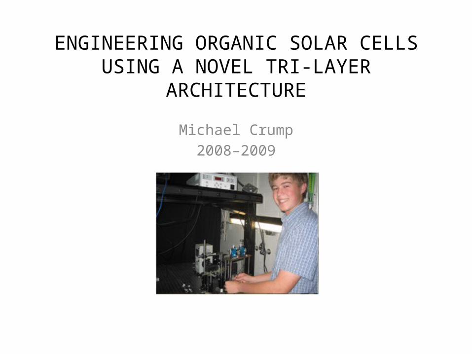
ENGINEERING ORGANIC SOLAR CELLS USING A NOVEL TRI-LAYER ARCHITECTURE
Michael Crump2008–2009
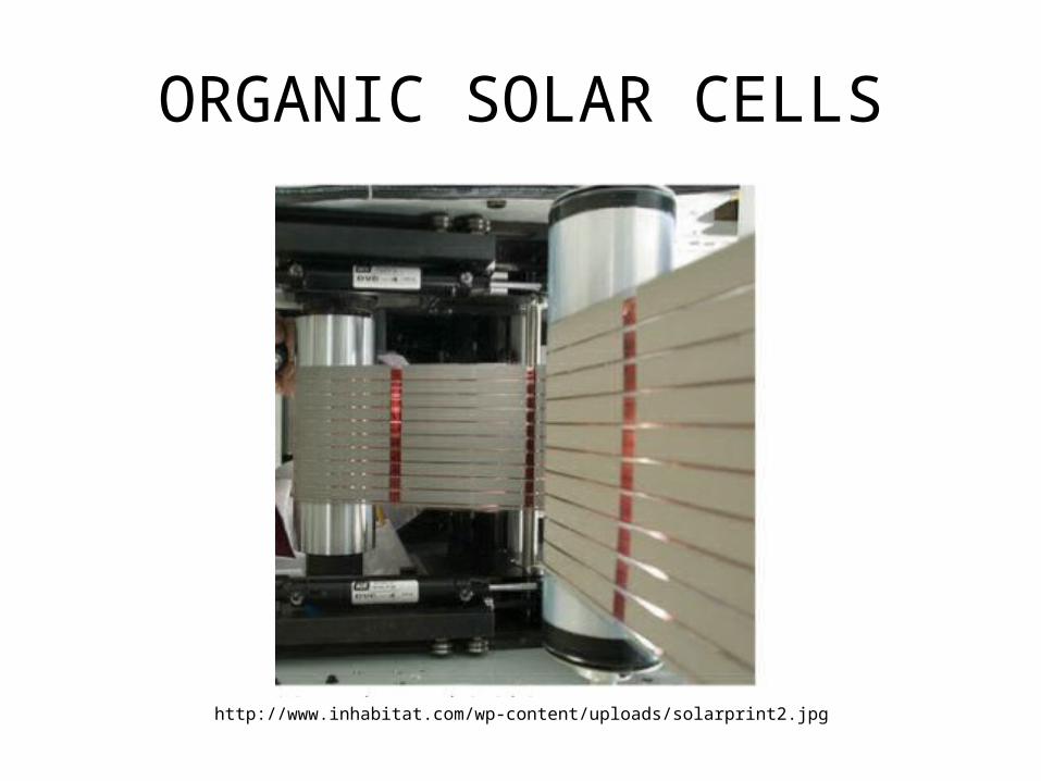
ORGANIC SOLAR CELLS
http://www.inhabitat.com/wp-content/uploads/solarprint2.jpg
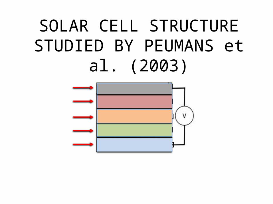
SOLAR CELL STRUCTURE STUDIED BY PEUMANS et al. (2003)
[1500 Å]
[200 Å]
[400 Å]
[100 Å]
[500 Å]
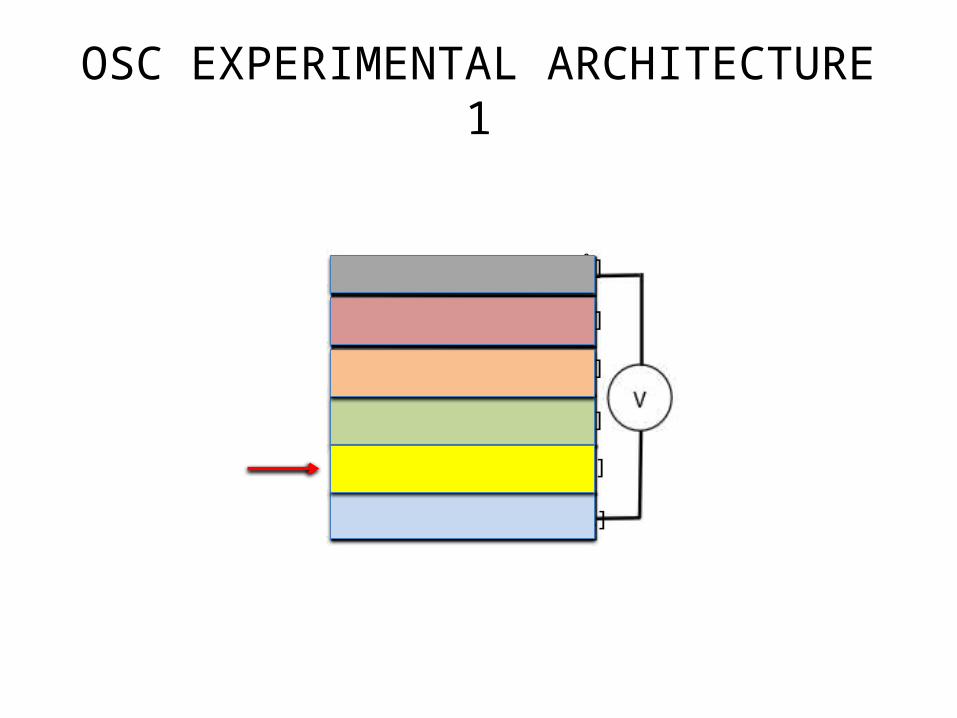
OSC EXPERIMENTAL ARCHITECTURE 1
[1500 Å]
[200 Å]
[10–100 Å]
[400 Å]
[100 Å]
[500 Å]
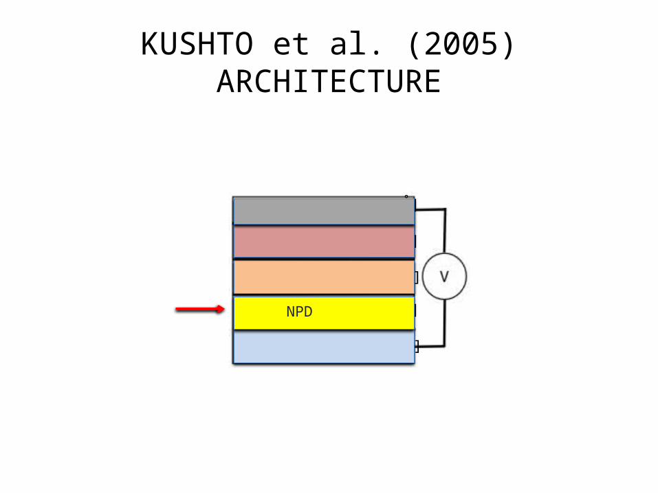
KUSHTO et al. (2005) ARCHITECTURE
[1500 Å]
[200 Å]
[400 Å]
[100 Å]
[500 Å]
NPD
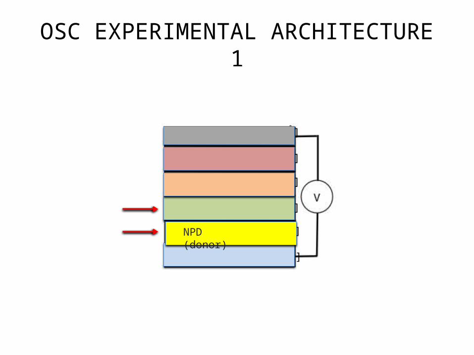
OSC EXPERIMENTAL ARCHITECTURE 1
[1500 Å]
[200 Å]
[10–100 Å]
[400 Å]
[100 Å]
[500 Å]
NPD (donor)
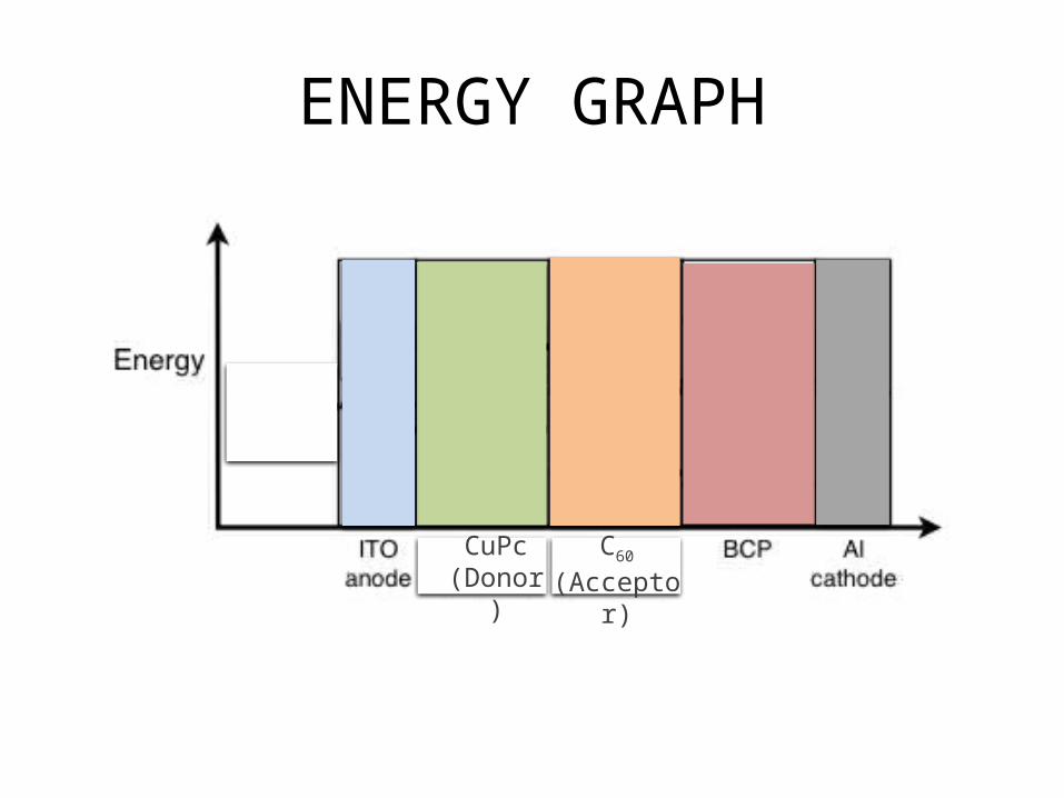
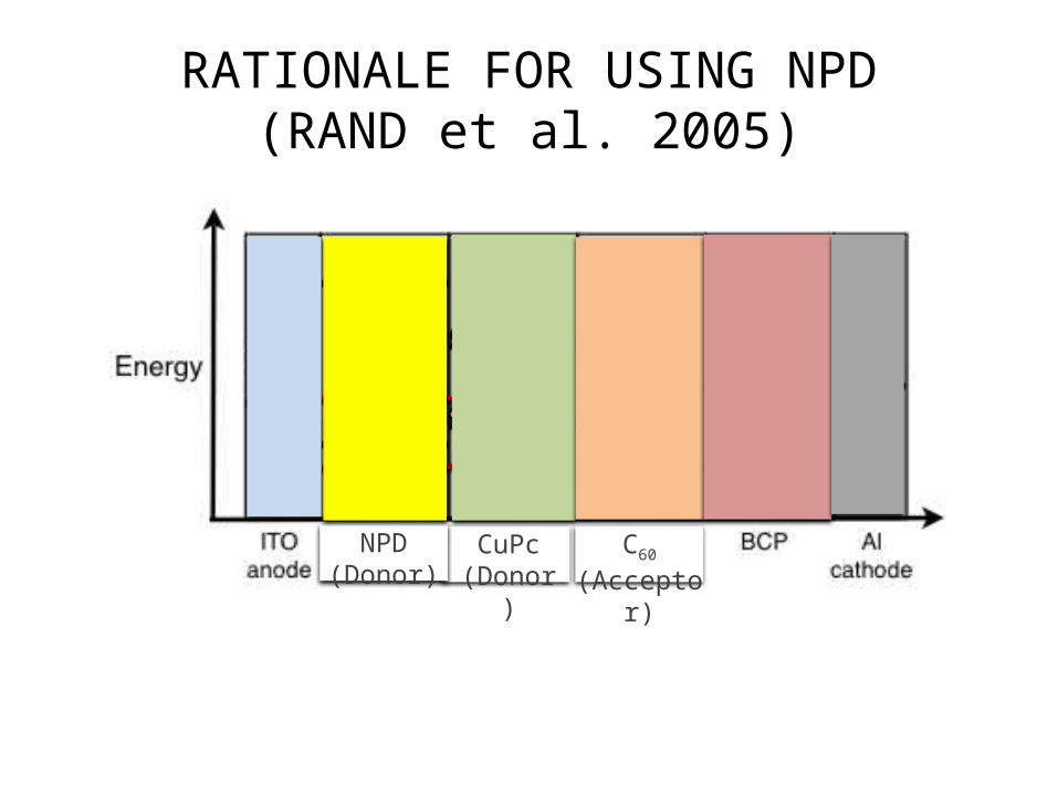
ENERGY GRAPH
donorCuPc
(Donor) donorC60
(Acceptor)

RATIONALE FOR USING NPD(RAND et al. 2005)
donorCuPc (Donor)
donorC60 (Acceptor)
donorNPD (Donor)
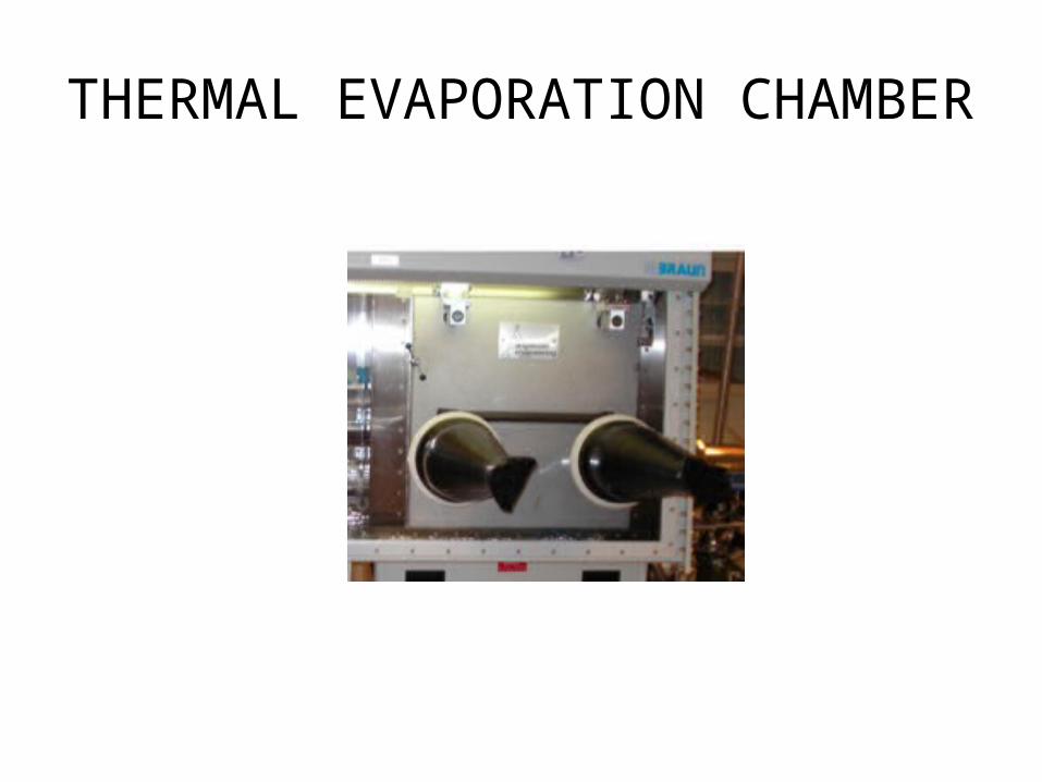
THERMAL EVAPORATION CHAMBER
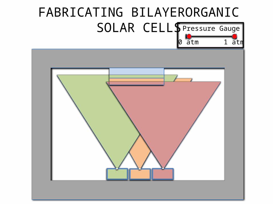
FABRICATING BILAYERORGANIC SOLAR CELLS Pressure Gauge
0 atm 1 atm
FABRICATING ORGANIC SOLAR CELLS
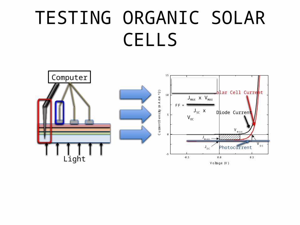
TESTING ORGANIC SOLAR CELLS
Computer
Light -0.5 0.0 0.5-5
0
5
10
15
Cu
rre
nt D
en
sity
(m
A/c
m^2
)Voltage (V)
Dark 71.72 mW/cm^2
JSC
VOC
VMAX
JMAX
JMAX
* VMAX
JSC
* VOC
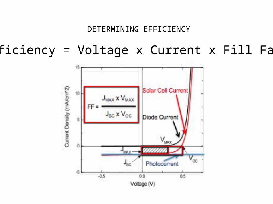
FF =
JMAX x VMAX
JSC x VOC
Solar Cell Current
Diode Current
Photocurrent
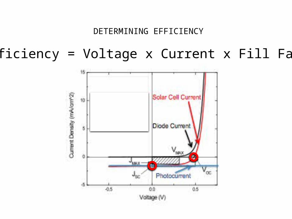
DETERMINING EFFICIENCY
Efficiency = Voltage x Current x Fill Factor
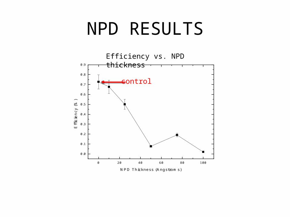
NPD RESULTS
0 20 40 60 80 100
0.0
0.1
0.2
0.3
0.4
0.5
0.6
0.7
0.8
0.9
Effic
ien
cy (
%)
NPD Thickness (Angstroms)
Efficiency vs. NPD thickness
control
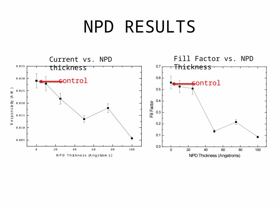
NPD RESULTS
0 20 40 60 80 100
0.005
0.010
0.015
0.020
0.025
0.030
0.035
Re
sp
on
siv
ity (
A/W
)
NPD Thickness (Angstroms)
Current vs. NPD thickness Fill Factor vs. NPD Thickness
control control
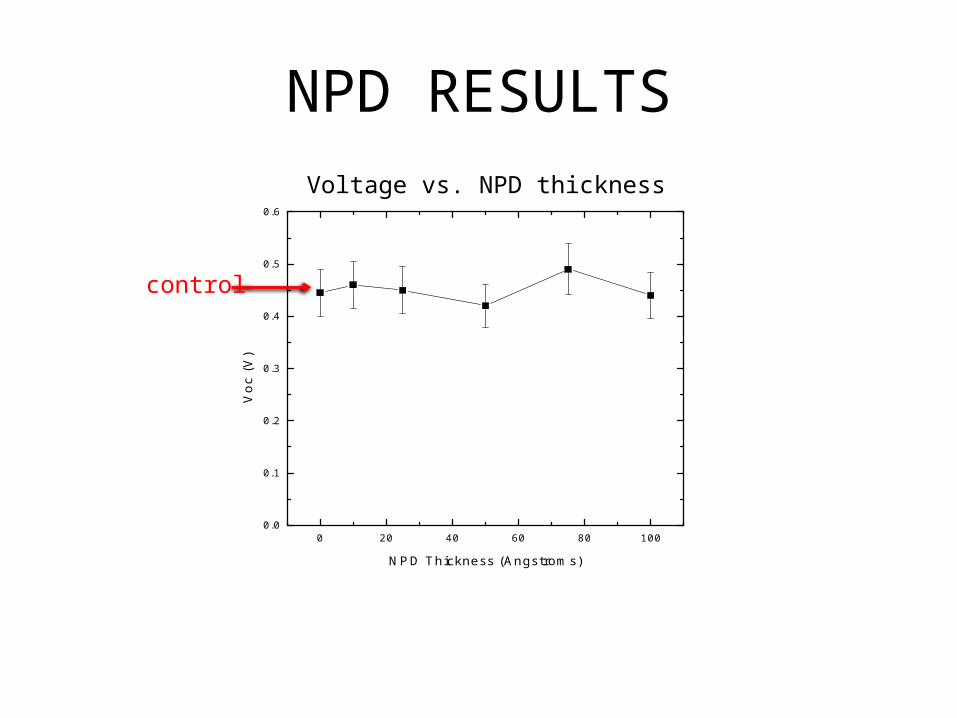
NPD RESULTS
0 20 40 60 80 1000.0
0.1
0.2
0.3
0.4
0.5
0.6
Vo
c (V
)
NPD Thickness (Angstroms)
Voltage vs. NPD thickness
control
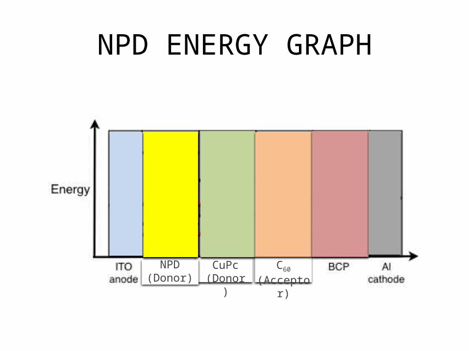
NPD ENERGY GRAPH
donorCuPc (Donor)
donorC60 (Acceptor)
donorNPD
(Donor)
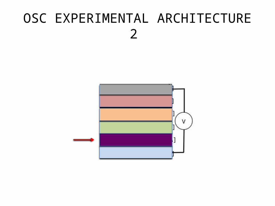
OSC EXPERIMENTAL ARCHITECTURE 2
[1500 Å]
[200 Å]
[10–100 Å]
[400 Å]
[100 Å]
[500 Å]
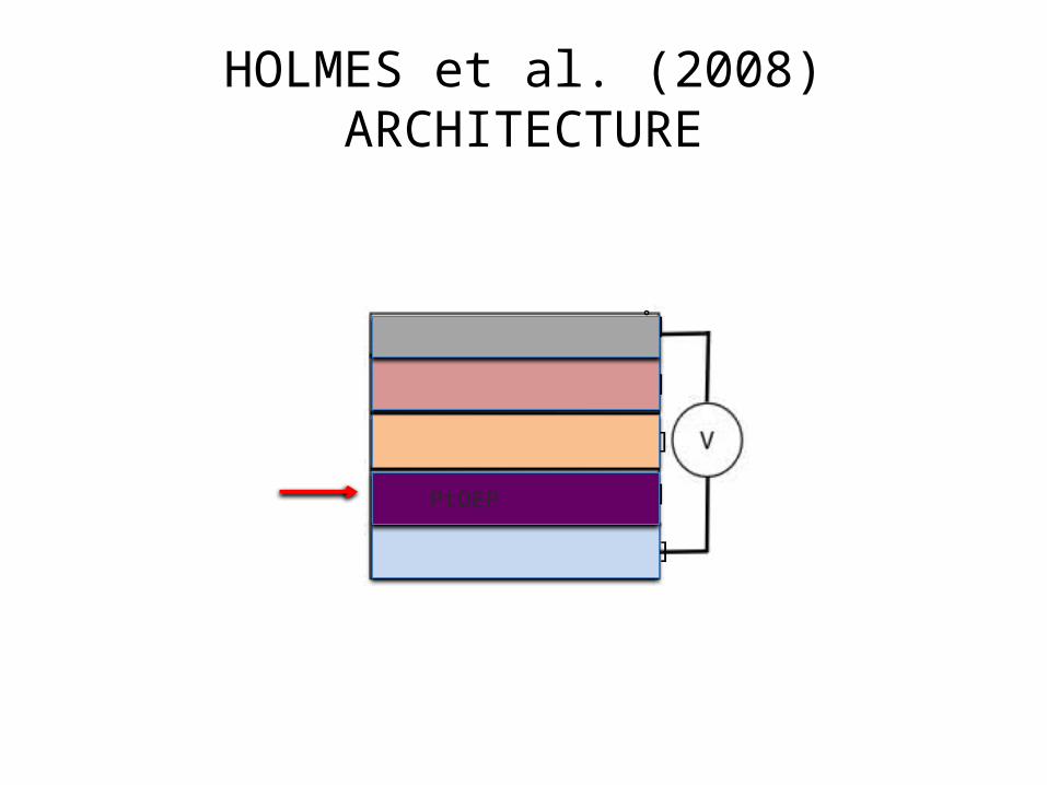
HOLMES et al. (2008) ARCHITECTURE
[1500 Å]
[200 Å]
[400 Å]
[100 Å]
[500 Å]
PtOEP
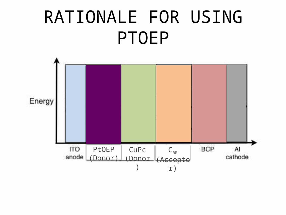
RATIONALE FOR USING PTOEP
donorCuPc (Donor)
donorC60 (Acceptor)
donorPtOEP (Donor)
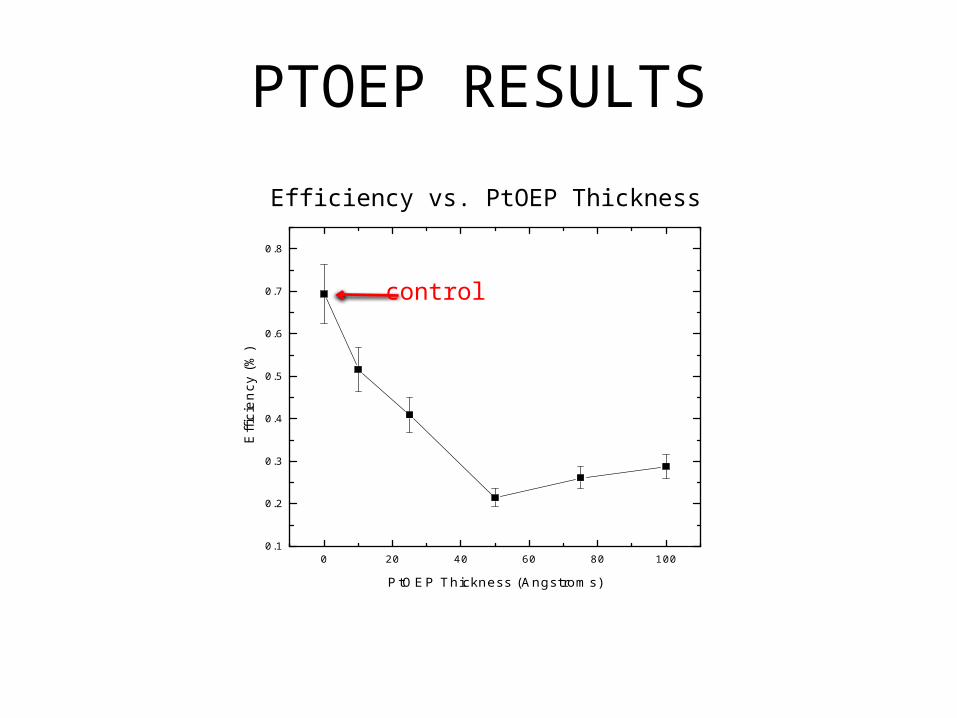
PTOEP RESULTS
0 20 40 60 80 1000.1
0.2
0.3
0.4
0.5
0.6
0.7
0.8
Effic
ien
cy (
%)
PtOEP Thickness (Angstroms)
Efficiency vs. PtOEP Thickness
control
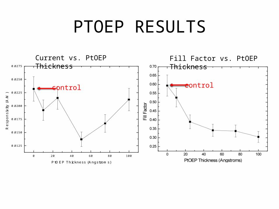
PTOEP RESULTS
0 20 40 60 80 100
0.0125
0.0150
0.0175
0.0200
0.0225
0.0250
0.0275
Re
spo
nsi
vity
(A
/W)
PtOEP Thickness (Angstroms)
Current vs. PtOEP Thickness Fill Factor vs. PtOEP Thickness
control control
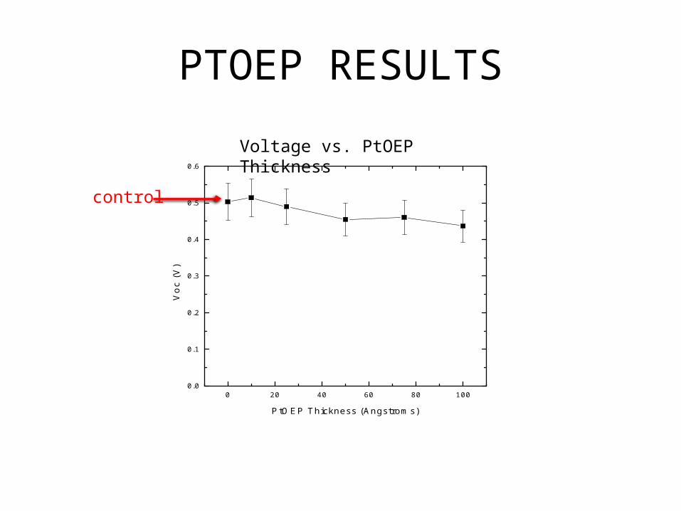
PTOEP RESULTS
0 20 40 60 80 1000.0
0.1
0.2
0.3
0.4
0.5
0.6
Vo
c (V
)
PtOEP Thickness (Angstroms)
Voltage vs. PtOEP Thickness
control
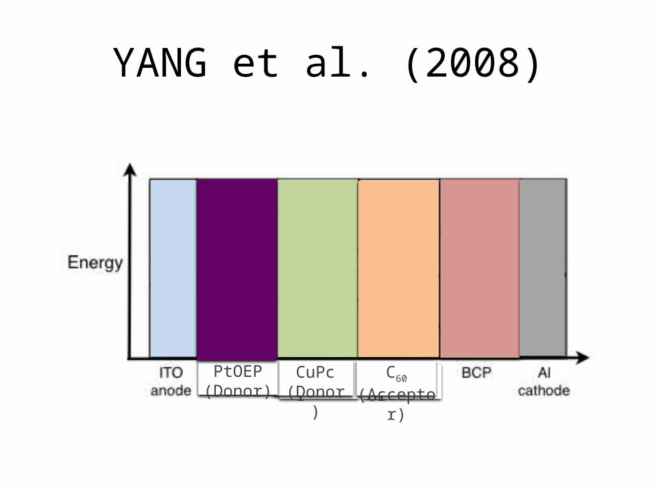
YANG et al. (2008)
donorDonor donorAcceptordonorCuPc (Donor)
donorC60 (Acceptor)
donorPtOEP (Donor)
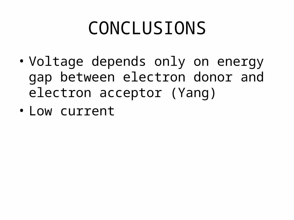
CONCLUSIONS
• Voltage depends only on energy gap between electron donor and electron acceptor (Yang)
• Low current
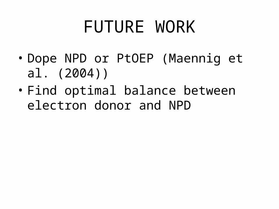
FUTURE WORK
• Dope NPD or PtOEP (Maennig et al. (2004))• Find optimal balance between electron donor
and NPD
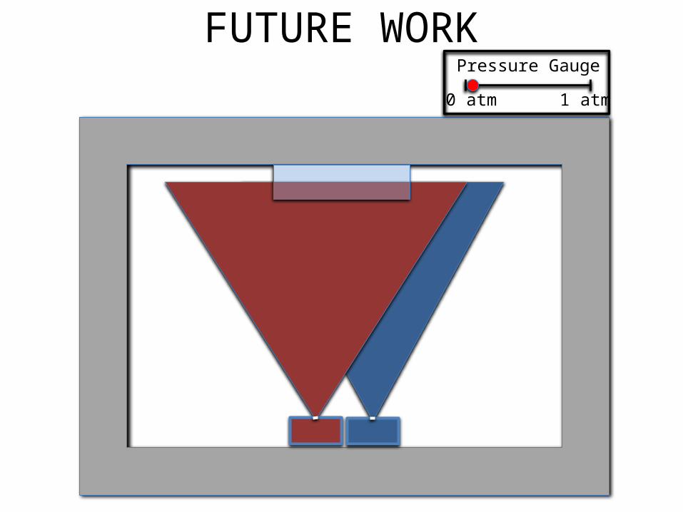
FUTURE WORKPressure Gauge
0 atm 1 atm
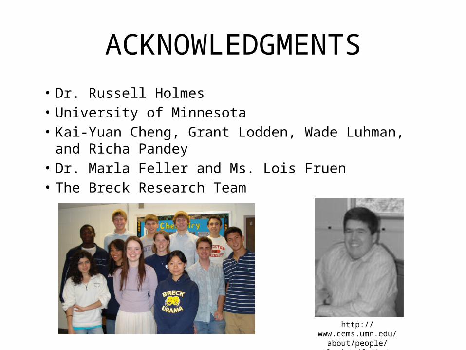
ACKNOWLEDGMENTS• Dr. Russell Holmes• University of Minnesota• Kai-Yuan Cheng, Grant Lodden, Wade Luhman, and Richa
Pandey• Dr. Marla Feller and Ms. Lois Fruen• The Breck Research Team
http://www.cems.umn.edu/about/people/facdetail.php?
cemsid=20785
ENGINEERING ORGANIC SOLAR CELLS USING A NOVEL TRI-LAYER ARCHITECTURE
Michael Crump2008–2009
RATIONALE FOR USING NPD(RAND et al. 2005)
donorCuPc (Donor)
donorC60 (Acceptor)
donorNPD (Donor)
DETERMINING EFFICIENCY
Efficiency = Voltage x Current x Fill Factor


