ENGINEERING MECHANICS BAA1113 - ocw.ump.edu.my
41
ENGINEERING MECHANICS BAA1113 Chapter 4: Force System Resultants (Static) by Pn Rokiah Bt Othman Faculty of Civil Engineering & Earth Resources [email protected]
Transcript of ENGINEERING MECHANICS BAA1113 - ocw.ump.edu.my

ENGINEERING MECHANICS
BAA1113
Chapter 4: Force System Resultants
(Static)
by
Pn Rokiah Bt OthmanFaculty of Civil Engineering & Earth Resources

Chapter Description
• Aims– To explain the Moment of Force (2D-scalar formulation & 3D-Vector
formulation)
– To explain the Principle Moment
– To explain the Moment of a Couple
– To explain the Simplification of a Force and Couple System
– To explain the Reduction of Simple Distributed Loading
• Expected Outcomes– Able to solve the problems of MOF and COM in the mechanics applications
by using principle of moments
• References– Russel C. Hibbeler. Engineering Mechanics: Statics & Dynamics, 14th
Edition

Chapter Outline
4.1 Moment of Force (MOF) –Part I
4.2 Principle of Moment –Part II
4.3 Moment of Couple (MOC) Part III
4.4 Simplification of a Force and Couple System
4.5 Reduction of Simple Distributed Loading- part IV

4.1 Moment of a Force
Moment can be defined as turning
force
The tendency of a force to rotate a
rigid body about any defined axis is
called the moment of the force about
the axis
It is also called a torque or twist
moment that tendency of a force to
rotate a body about the axis
It is a vector, so its has both
magnitude and direction (right
handrule)
+ve CCW & -ve CW
Unit used is N.m
In a 2-D case, the magnitude of
the moment
What is
Moment?Perpendicular
distance between the
point about which
the moment is
required and the line
of action of force
Force
acting on
the body
Mo = F d

Application of Moment (turning effect)
Seesaw-how to
balance?
Causes of motionDay life activity-
moment arm
How does wheel
size affect
performance?

Application of Moment (turning effect)
Measure the
moment
arm(length) to
produce rotary
power
Measure the
forces (weight
transfer) and
moment arm
Measure the
forces/effort to
make sure good
swing
Measure the
forces/effort
to make sure
good swing

Application of Moment (turning effect)
Measure the
input forces
and level to
make sure
output force
Measure the
effort/ load to
make easy
work

Moment factor
MOF is bigger if
acts further from
the pivot
MOF is bigger
if the force is
bigger
MOF is bigger if it
acts at 90 to the body
it acts on

Moment of a force in 2-D
(scalar formulation)
Magnitude
•MO = Fd
•d is the perpendicular distancefrom point O to the line of actionof the force
Direction
•Direction of MO is specified byusing “right hand rule”
•direction of MO is eitherclockwise (CW) or counter-clockwise (CCW), depending onthe tendency for rotation
Fa
b
d
O
MO = F d
direction is counter-clockwise. MRo = ∑Fd

Moment of a force in 2-D
(scalar formulation)
Force F tends to
rotate the beam
clockwise about A
with moment
MA = F dA
Force F tends to
rotate the beam
clockwise about B
with moment
MB = F dB
Hence support at A prevents the rotation
Moment of a force does not always cause rotation

Example 4.1
This is an example of a 2-D or coplanar force system. Determine the
MOF about point O
Step 3: assume
tendency to
rotate/ moment
Step 1: FBD
(Sketch outline
shape)
Step 2: det. The
line of action/
moment arm (d)
Step 4: use
formula
MO = Fd = (100 N) (2 m) = 200 Nm (CW)

Solution Example 4.1
This is an example of a 2-D or coplanar force system. Determine the
MOF about point O
MO = Fd = (50 N) (0.75 m) = 37.5 Nm (CW)
MO = Fd = (40 N) (4 m + 2 cos 30° m) = 229 Nm (CW)
Step 2: det. The
line of action/
moment arm (d)
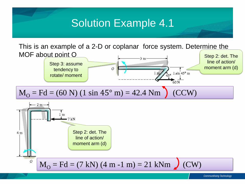
Solution Example 4.1
This is an example of a 2-D or coplanar force system. Determine the
MOF about point O
MO = Fd = (60 N) (1 sin 45° m) = 42.4 Nm (CCW)
MO = Fd = (7 kN) (4 m -1 m) = 21 kNm (CW)
Step 3: assume
tendency to
rotate/ moment
Step 2: det. The
line of action/
moment arm (d)
Step 2: det. The
line of action/
moment arm (d)

Example 4.2
This is an example of a 2-D or coplanar force system. Determine the
moments of the 800 N force acting on the frame about points A,B,C
and D
Step 3: assume
tendency to
rotate/ moment
Step 1: FBD
(Sketch outline
shape)
Step 2: det. The
line of action/
moment arm (d)
Step 4: use
formula
MA = Fd = (800 N) (1.5 +1 m) = 2000 Nm (CW)

Solution Example 4.2
This is an example of a 2-D or coplanar force system. Determine the
moments of the 800 N force acting on the frame about points A,B,C
and D
Step 3: assume
tendency to
rotate/ moment
Step 1: FBD
(Sketch outline
shape)
Step 2: det. The
line of action/
moment arm (d)
Step 4: use
formula
MB = Fd = (800 N) (1.5 m) = 1200 Nm (CW)

Example 4.2
This is an example of a 2-D or coplanar force system. Determine the
moments of the 800 N force acting on the frame about points A,B,C
and D
Step 2: line of
action F passes
through C
Step 4: use
formula
MC = Fd = (800 N) ( 0 m) = 0 Nm
Moment is
zero
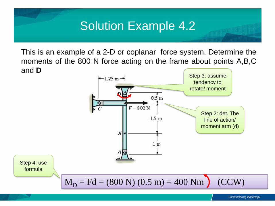
Solution Example 4.2
This is an example of a 2-D or coplanar force system. Determine the
moments of the 800 N force acting on the frame about points A,B,C
and DStep 3: assume
tendency to
rotate/ moment
Step 2: det. The
line of action/
moment arm (d)
Step 4: use
formula
MD = Fd = (800 N) (0.5 m) = 400 Nm (CCW)
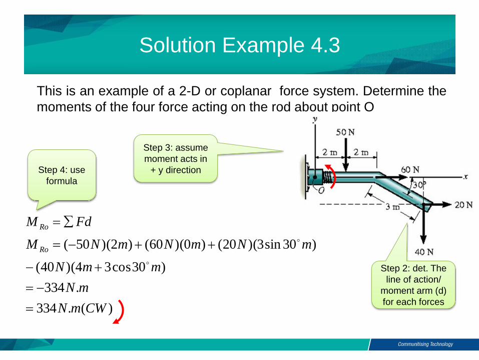
Solution Example 4.3
This is an example of a 2-D or coplanar force system. Determine the
moments of the four force acting on the rod about point O
Step 4: use
formula
Step 3: assume
moment acts in
+ y direction
Step 2: det. The
line of action/
moment arm (d)
for each forces )(.334
.334
)30cos34)(40(
)30sin3)(20()0)(60()2)(50(
CWmN
mN
mmN
mNmNmNM
FdM
Ro
Ro

Example 4.4
Determine the moments of the 100 N force acting on the frame aboutpoint O
assume
moment acts in
+ y direction Resolve forces
into x & y

Solution Example 4.4
Determine the moments of the 100 N force acting on the frame aboutpoint O
assume
moment acts in
+ y direction Resolve forces
into x & y
+ Fy = – 100 (3/5) N
+ Fx = 100 (4/5) N
+ MO = {– 100 (3/5)N (5 m) – (100)(4/5)N (2 m)} N·m
= – 460 N·m or 460 N·m CW

Moment of a force in 3-D
(Vector formulation)
Moments in 3-D can be calculated
using scalar (2-D) approach, but it
can be difficult (finding d when
forces in 3-D) and time
consuming
It it easier to use vector cross
product
r is the position vector from point O to
any point on the line of action of F
MO = r F

Moment of a force in 3-D
(Vector formulation)
Moment can be expressed as
By expanding the above equation using 2 2 determinants
MO = (ry Fz - rz Fy) i (rx Fz - rz Fx ) j + (rx Fy - ry Fx ) k

Cross Product
The magnitude and direction of the resulting vector can be written as
C = A B
C = A B = A B sin uC
What is
vector cross
product?
It is a
vector
operation
Unit vector uC
defines the direction of vector C
Scalar A B sin defines
the magnitude of
vector C
0° ≤ θ ≤ 180°
The cross product of two vectors A and B results in vector C

Cross Product
Laws of Operations1. Commutative law is not valid
A X B ≠ B X ARather,
A X B = - B X A Shown by the right hand rule Cross product A X B yields a
vector opposite in direction to C
B X A = -C

Cross Product
Laws of Operations
2. Multiplication by a Scalar
a( A X B ) = (aA) X B = A X (aB) = ( A X B )a
3. Distributive Law
A X ( B + D ) = ( A X B ) + ( A X D )
Proper order of the cross product must be maintained since they are not commutative

Cross Product
i j = k
i i = 0
vector crossed into itself is zero
Direction is
determine
using right
hand rule
Cartesian Vector FormulationUse C = AB sinθ on pair of Cartesian unit vectors
For i X j, (i)(j)(sin90°) = (1)(1)(1) = 1
Use the circle for the results Crossing CCW yield
positive CW yields negative
results
j j = 0 k k = 0i j = k
k i = j
j k = i
i k = -j
j i = -k
k j = -i

Cross Product Rules
Each
component can
be determine
using 2X2
determinants
Cross
product can
be written as
a determinant
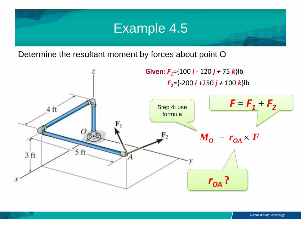
Example 4.5
Determine the resultant moment by forces about point O
Given: F1={100 i - 120 j + 75 k}lb
F2={-200 i +250 j + 100 k}lb
MO = rOA F
Step 4: use
formula
rOA ?
F = F1 + F2

Solution Example 4.5
Determine the resultant moment by forces about point O
MO = rOA F
rOA
F = F1 + F2
= { (100 - 200) i + (-120 + 250) j + (75 + 100) k} lb
= {-100 i +130 j + 175 k} lb
rOA = {4 i + 5 j + 3 k} ft
Use vector cross product
i j k4 5 3
-100 130 175
MO = = [{5(175) – 3(130)} i – {4(175) –
3(-100)} j + {4(130) – 5(-100)} k] ft·lb
= {485 i – 1000 j + 1020 k} ft·lb

Example 4.6
Determine the moment of F about point A
MO = rAC F Step 4: use
formula
rAC ?
F?

Solution Example 4.6
Determine the moment of F about point A
MO = rAC F
F ={ (80 cos30) sin 40 i
+ (80 cos30) cos 40 j 80 sin30 k} N
={44.53 i + 53.07 j 40 k } N
rAC ={0.55 i + 0.4 j 0.2 k } m
MA =
= { -5.39 i + 13.1 j +11.4 k } N·m
i j k0.55 0.4 0.2
44.53 53.07 40
Det. moment
by using cross
product

Example 4.7
The pole is subjected to a 60N force that is directed from C to B. Determine
the magnitude of the moment created by this force about the support at A

Solution example 4.7
Either one of the two position vectors can be used for the solution, since MA = rB x F or MA = rC x F
Position vectors are represented as
rB = {1i + 3j + 2k} m and
rC = {3i + 4j} m
Force F has magnitude 60N
and is directed from C to B

kji
kji
FXrM
Nkji
kjiN
uNF
BA
F
)]40(3)20(1[)]40(2)40(1[)]20(2)40(3[
402040
231
402040
)2()1()2(
)092)493)31()60(
)60(
222
Solution example 4.7

mN
M
mNkjiM
kji
kji
FXrM
A
A
CA
.224
)100()120()160(
.100120160
)]40(4)20(3[)]40(0)40(3[)]20(0)40(4[
402040
043
222
Solution example 4.7

Three forces act on the rod. Determine the resultant moment they
create about the flange at O and determine the coordinate direction
angles of the moment axis
Example 4.8

Solution example 4.8
Position vectors are directed from pointO to each force rA = {5j} m and rB = {4i + 5j - 2k} m
For resultant moment about O,
mNkji
kjikjikji
FXrXFrFXrFXrM CBARo
.604030
304080
254
0500
050
204060
050
)( 321

Solution example 4.8
For magnitude
For unit vector defining the direction of moment axis,
kji
kji
M
Mu
mNM
Ro
Ro
Ro
76852.05121.03941.0
10.78
604030
.10.78)60()40()30( 222

Solution example 4.8
For the coordinate angles of the moment axis,
8.39;7682.0cos
121;5121.0cos
4.67;3841.0cos
Conclusion of The Chapter 4
• Conclusions
- The Moment of a Force been identified
- The Vector cross product have been implemented to solve
Moment problems in Coplanar Forces Systems

Credits to:
Dr Nurul Nadhrah Bt Tukimat
En Khalimi Johan bin Abd Hamid
Roslina binti Omar


![Engineering Mechanics - DrChawin.com Engineering Mechanics I [Statics] Lecture 1 Page 1 of 12 Lecture 1: Introduction to Engineering Mechanics Engineering mechanics is the …](https://static.fdocuments.in/doc/165x107/5aa4d6047f8b9ab4788c63da/engineering-mechanics-engineering-mechanics-i-statics-lecture-1-page-1-of-12.jpg)