Engineering Manual
7
12/4/13 TSPS Engineering Manual weh.maritime.edu/campus/tsps/manual/losys.html 1/7 T.S. Patriot State Engineering Manual Patriot State was the training ship of the Massachusetts Maritime Academy from 1986 to 1998. [ Next Section] [ Contents] [ Info] Main Lube Oil System The primary function of the Lube Oil system is to supply lubricating oil at the proper pressure and temperature to the main propulsion turbines and reduction gears. The lube oil not only lubricates the machinery, but it also cools and helps reduce rusting. Secondary functions include purifying oil that has become contaminted and transferring oil to or from the sump tank, gravity tank, storage tank, settling tank, sludge tank, or deck connections. The lube oil service system is provided with two lube oil service pumps. One vertical rotary, motor driven and one reciprocating pump connected so that one unit is available for standby operation while the other unit is supplying the system. The lube oil service pump has a capacity of 435 gpm and lube oil standby 450 gpm, at a discharge pressure of 57.5 psig, and one pump by itself is capable of supplying the entire oil requirements of the main propulsion unit under any power conditions. The lube oil system is provided with two coolers, either of which is capable of handling the full requirements of the system with the other on standby. These coolers are of the single pass, shell and tube type capable of cooling 435 gpm of oil, with a viscosity of 500 SSU at 100° F., when supplied with 470 gpm of sea water at 85° F. Note that oil pressure is
-
Upload
babu-aravind -
Category
Documents
-
view
22 -
download
4
description
oil
Transcript of Engineering Manual

12/4/13 TSPS Engineering Manual
weh.maritime.edu/campus/tsps/manual/losys.html 1/7
T.S. Patriot State Engineering
ManualPatriot State was the training ship of the Massachusetts Maritime
Academy from 1986 to 1998.
[Next Section] [Contents] [Info]
Main Lube Oil System
The primary function of the Lube Oil system is to supply lubricating oil at
the proper pressure and temperature to the main propulsion turbines
and reduction gears. The lube oil not only lubricates the machinery, but it
also cools and helps reduce rusting. Secondary functions include purifying
oil that has become contaminted and transferring oil to or from the sump
tank, gravity tank, storage tank, settling tank, sludge tank, or deck
connections.
The lube oil service system is provided with two lube oil service
pumps. One vertical rotary, motor driven and one reciprocating pump
connected so that one unit is available for standby operation while the
other unit is supplying the system. The lube oil service pump has a
capacity of 435 gpm and lube oil standby 450 gpm, at a discharge
pressure of 57.5 psig, and one pump by itself is capable of supplying the
entire oil requirements of the main propulsion unit under any power
conditions.
The lube oil system is provided with two coolers, either of which is
capable of handling the full requirements of the system with the other on
standby. These coolers are of the single pass, shell and tube type capable
of cooling 435 gpm of oil, with a viscosity of 500 SSU at 100° F., when
supplied with 470 gpm of sea water at 85° F. Note that oil pressure is

12/4/13 TSPS Engineering Manual
weh.maritime.edu/campus/tsps/manual/losys.html 2/7
greater than sea water pressure.
The coolers are mounted in parallel and the piping arranged so that
either unit may be by-passed. There is a drain connection from each
cooler to a common drain line terminating in the main sump tank. A 5
pound steam connection is provided in the inlet head of each cooler to
allow for the warming of the oil, if necessary, prior to starting up the main
propulsion unit. Steam for this purpose is supplied via a temporary hose
from the auxiliary exhaust and bleeder steam system.
Storage tanks are of welded steel construction and large enough to
hold at least one complete change of oil for the entire system. One storage
tank of 3600 gallon capacity may be filled from the service pump
discharge or the deck connections. The tank, which contains only clean oil,
may also be filled with oil from the purifier discharge. The tank is
equipped with a vent to the atmosphere, a pneumatic type level indicator,
a sound tube, and an overflow line which discharges to the main sump
tank via an open funneled line.
A 3600 gallon settling tank is installed as part of the lube oil system.
The tank is of welded steel construction and has enough capacity to hold
all the oil from the entire system. The bottom is sloped to facilitate
drainage to the purifier and sludge tank, with a high drain connection to
the main lubricating system. The steam coils are fitted to heat the oil for
settling purposes. The tank is normally used when settling oil during
batch purification. The tank is provided with thermometer, vent,
pneumatic type level indicator as well as a sounding tube, heating coils,
and an overflow line which discharges to the main sump tank via an open
funneled line.
The 1800 gallon gravity tank is also of welded steel construction and
located in the engine room at sufficient heights to maintain 10 psi oil
pressure at the highest bearing. The gravity tank must carry at least
three minutes supply of oil below the overflow pipe connection, when the
machinery is operating at maximum continuous power. This reserve oil is
to allow time to stop the shaft in the event that the lube oil pumps fail.
12/4/13 TSPS Engineering Manual
weh.maritime.edu/campus/tsps/manual/losys.html 3/7
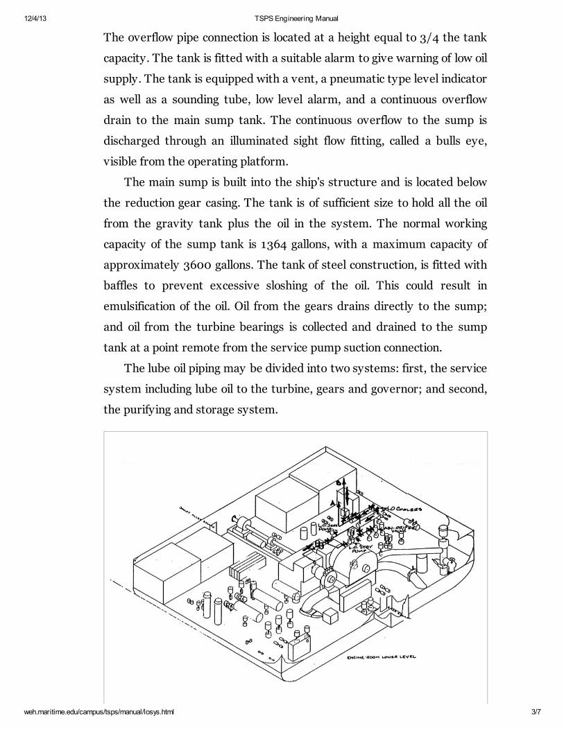
The overflow pipe connection is located at a height equal to 3/4 the tank
capacity. The tank is fitted with a suitable alarm to give warning of low oil
supply. The tank is equipped with a vent, a pneumatic type level indicator
as well as a sounding tube, low level alarm, and a continuous overflow
drain to the main sump tank. The continuous overflow to the sump is
discharged through an illuminated sight flow fitting, called a bulls eye,
visible from the operating platform.
The main sump is built into the ship's structure and is located below
the reduction gear casing. The tank is of sufficient size to hold all the oil
from the gravity tank plus the oil in the system. The normal working
capacity of the sump tank is 1364 gallons, with a maximum capacity of
approximately 3600 gallons. The tank of steel construction, is fitted with
baffles to prevent excessive sloshing of the oil. This could result in
emulsification of the oil. Oil from the gears drains directly to the sump;
and oil from the turbine bearings is collected and drained to the sump
tank at a point remote from the service pump suction connection.
The lube oil piping may be divided into two systems: first, the service
system including lube oil to the turbine, gears and governor; and second,
the purifying and storage system.
12/4/13 TSPS Engineering Manual
weh.maritime.edu/campus/tsps/manual/losys.html 4/7
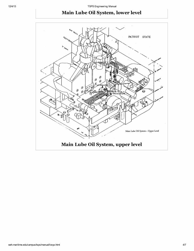
Main Lube Oil System, lower level
Main Lube Oil System, upper level
12/4/13 TSPS Engineering Manual
weh.maritime.edu/campus/tsps/manual/losys.html 5/7
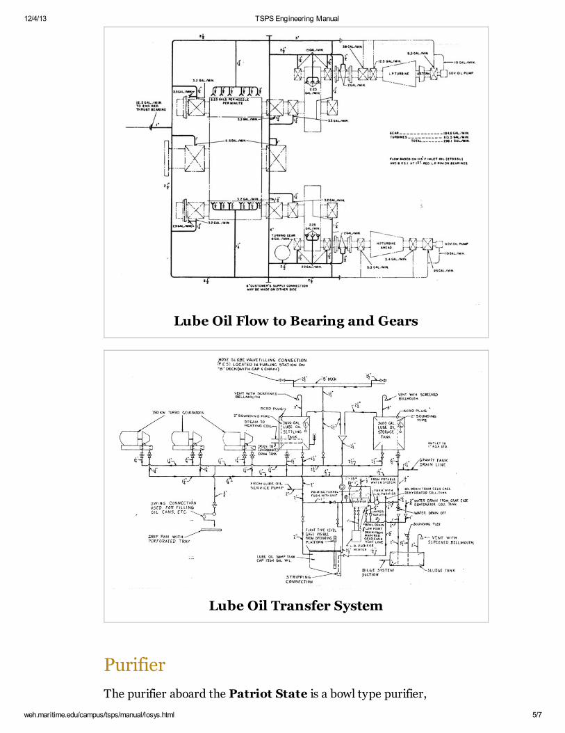
Lube Oil Flow to Bearing and Gears
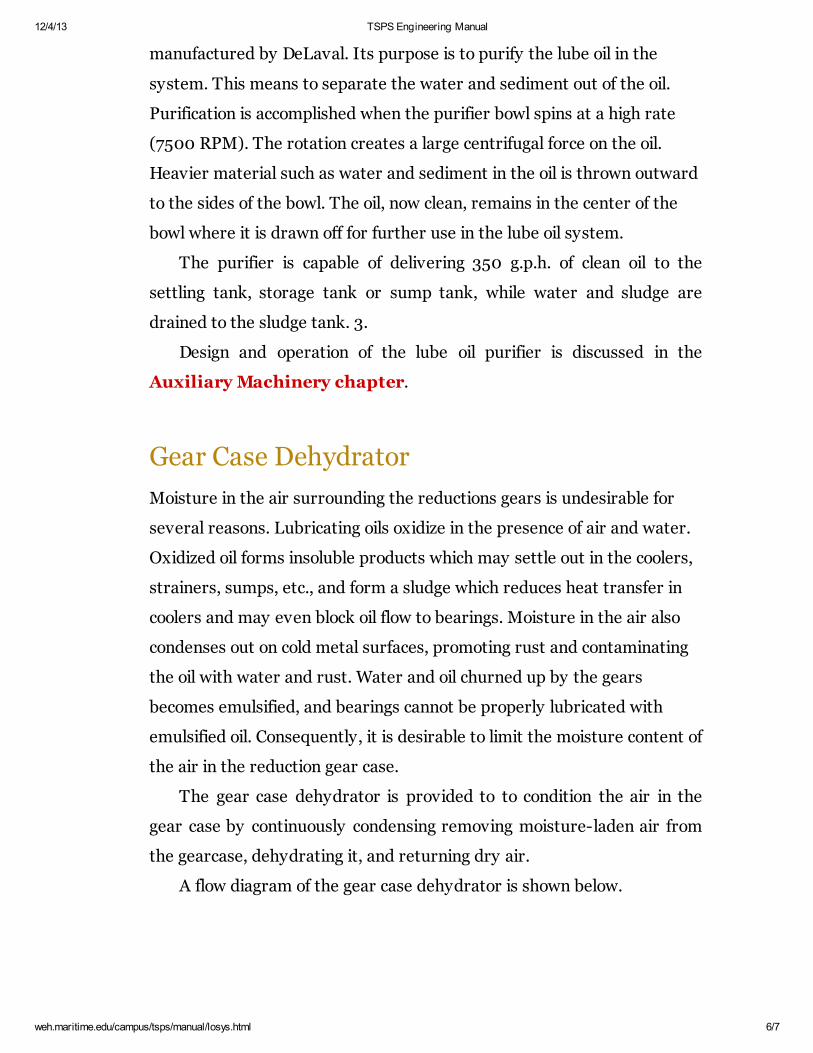
Lube Oil Transfer System
Purifier
The purifier aboard the Patriot State is a bowl type purifier,
12/4/13 TSPS Engineering Manual
weh.maritime.edu/campus/tsps/manual/losys.html 6/7
manufactured by DeLaval. Its purpose is to purify the lube oil in the
system. This means to separate the water and sediment out of the oil.
Purification is accomplished when the purifier bowl spins at a high rate
(7500 RPM). The rotation creates a large centrifugal force on the oil.
Heavier material such as water and sediment in the oil is thrown outward
to the sides of the bowl. The oil, now clean, remains in the center of the
bowl where it is drawn off for further use in the lube oil system.
The purifier is capable of delivering 350 g.p.h. of clean oil to the
settling tank, storage tank or sump tank, while water and sludge are
drained to the sludge tank. 3.
Design and operation of the lube oil purifier is discussed in the
Auxiliary Machinery chapter.
Gear Case Dehydrator
Moisture in the air surrounding the reductions gears is undesirable for
several reasons. Lubricating oils oxidize in the presence of air and water.
Oxidized oil forms insoluble products which may settle out in the coolers,
strainers, sumps, etc., and form a sludge which reduces heat transfer in
coolers and may even block oil flow to bearings. Moisture in the air also
condenses out on cold metal surfaces, promoting rust and contaminating
the oil with water and rust. Water and oil churned up by the gears
becomes emulsified, and bearings cannot be properly lubricated with
emulsified oil. Consequently, it is desirable to limit the moisture content of
the air in the reduction gear case.
The gear case dehydrator is provided to to condition the air in the
gear case by continuously condensing removing moisture-laden air from
the gearcase, dehydrating it, and returning dry air.
A flow diagram of the gear case dehydrator is shown below.

12/4/13 TSPS Engineering Manual
weh.maritime.edu/campus/tsps/manual/losys.html 7/7
Gear Case Dehydrator
[Next Section] [Contents] [Info]
Direct comments to William Haynes [email protected]
Mon, Jul 1, 1996
TSPS Engineering Manual ©1995 Massachusetts Maritime Academy