ENGINEERING, LLC - SuperchargersOnline · This product is protected by state common law, copyright...
52
DP/N: 4HS020-010 v4.0 10/21/2008 ® 1650 Pacific Avenue, Channel Islands CA 93033-9901 • Phone: 805 247-0226 Fax: 805 247-0669 • www.vortechsuperchargers.com • M-F 8:00AM - 4:30PM (PST) ENGINEERING, LLC Honda S2000 Supercharger System Installation Instructions 2000-2008 Model Years 2000-2005 50 State Smog Legal Per CARB EO #D-213-23 *2006-2008 Legal in California only for racing vehicles which may never be used upon a highway.
Transcript of ENGINEERING, LLC - SuperchargersOnline · This product is protected by state common law, copyright...

DP/N: 4HS020-010 v4.0 10/21/2008
®
1650 Pacific Avenue, Channel Islands CA 93033-9901 • Phone: 805 247-0226 Fax: 805 247-0669 • www.vortechsuperchargers.com • M-F 8:00AM - 4:30PM (PST)
ENGINEERING, LLC
Honda S2000Supercharger SystemInstallation Instructions
2000-2008 Model Years
2000-2005 50 State Smog Legal Per CARB EO #D-213-23
*2006-2008 Legal in California only for racing vehicles which may never be used upon a highway.

P/N: 4HS020-010 ©2008 Vortech Engineering, LLC All Rights Reserved, Intl. Copr. Secured 21OCT08 v4.0 S2000(4HS020-010v4.0)
iiii
FOREWORD
Take note of the following before proceeding:1. Proper installation of this supercharger kit requires general automotive mechanic knowledge and experience. Please browse through each step of this instruction manual prior to beginning the installation to determine if you should refer the job to a professional installer/technician. Please contact your dealer or Vortech Engineering for possible installers in your area.
2. This product was designed for use on stock (un-modified, OEM) vehicles. The PCM (computer), engine, transmission, drive axle ratios and tire O.D. must be stock. If the vehicle or engine has been modified in any way, check with Vortech prior to installa-tion and use of this product.
3. Use only premium grade fuel with a minimum of 91 octane (R+M/2).4. Always listen for any sign of detonation (knocking/pinging) and discontinue hard use
(no boost) until the problem is resolved.5. Vortech is not responsible for any clutch, transmission, drive-line or engine damage.
Exclusions from Vortech warranty coverage considerations include, but not limited to:
1. Neglect, abuse, lack of maintenance, abnormal operation or improper installation.2. Continued operation with an impaired vehicle or sub-system.3. The combined use of Vortech components with other modifications such as, but not limit-
ed to, exhaust headers, aftermarket camshafts, nitrous oxide, third party PCM program-ming or other such changes.
©2008 VORTECH ENGINEERING, LLC All rights reserved. No part of this publication may be reproduced, transmitted, transcribed, or translated
into another language in any form, by any means without written permission of Vortech Engineering, LLC.
This manual provides information on the installation, maintenance and service of the Vortech supercharger kit expressly designed for this vehicle. All information, illustra-tions and specifications contained herein are based on the latest product information
available at the time of this publication. Changes to the manual may be made at any time without notice. Contact Vortech Engineering for any additional information regarding this kit and any of these modifications at (805) 247-0226 8:00am-4:30pm PST.

P/N: 4HS020-010 ©2008 Vortech Engineering, LLC
All Rights Reserved, Intl. Copr. Secured 21OCT08 v4.0 S2000(4HS020-010v4.0)
iii
This product is protected by state common law, copyright and/or patent. All legal rights therein are reserved. The design, layout, dimensions, geometry, and engineer-ing features shown in this product are the exclusive property of Vortech Engineering, LLC. This product may not be copied or duplicated in whole or part, abstractly or fundamentally, intentionally or fortuitously, nor shall any design, dimension, or other information be incorporated into any product or apparatus without prior written con-sent of Vortech Engineering, LLC.
IMPORTANT NOTES
2006-2008 ModelsThis kit requires an ECU (Engine Control Unit) Reflash. Prior to kit installation, the ECU must be sent directly to Hondata by the installing customer (the charge for this service and shipping has been included in the purchase price). See Step 17 for ECU location.
• Included in this kit is a prepaid next-day air shipping box and a credit tag for one (1) Vortech ECU Reflash.
• Mail to Hondata the enclosed "ECU Reflash Credit Tag" (send original tag - no photocopies will be accepted) and ECU in the supplied box.
• Turnaround time will be 1-2 days (each application varies).
NOTE: Vortech Engineering is not responsible for engine or ECU damage due to an improperly installed/mishandled ECU.

P/N: 4HS020-010 ©2008 Vortech Engineering, LLC All Rights Reserved, Intl. Copr. Secured 21OCT08 v4.0 S2000(4HS020-010v4.0)
iviv
TABLE OF CONTENTS
FOREWORD . . . . . . . . . . . . . . . . . . . . . . . . . . . . . . . . . . . . . . . . . . . . . . . . . . . . . . . . . . . . . . . . . ii
IMPORTANT NOTES . . . . . . . . . . . . . . . . . . . . . . . . . . . . . . . . . . . . . . . . . . . . . . . . . . . . . . . . . . . iii
TABLE OF CONTENTS. . . . . . . . . . . . . . . . . . . . . . . . . . . . . . . . . . . . . . . . . . . . . . . . . . . . . . . . . iv
TOOLS & SUPPLY REQUIREMENTS . . . . . . . . . . . . . . . . . . . . . . . . . . . . . . . . . . . . . . . . . . . . . v
PARTS LIST - 2000-2003 HONDA S2000. . . . . . . . . . . . . . . . . . . . . . . . . . . . . . . . . . . . . . . . . . . vi
PARTS LIST - 2004 HONDA S2000 . . . . . . . . . . . . . . . . . . . . . . . . . . . . . . . . . . . . . . . . . . . . . . viii
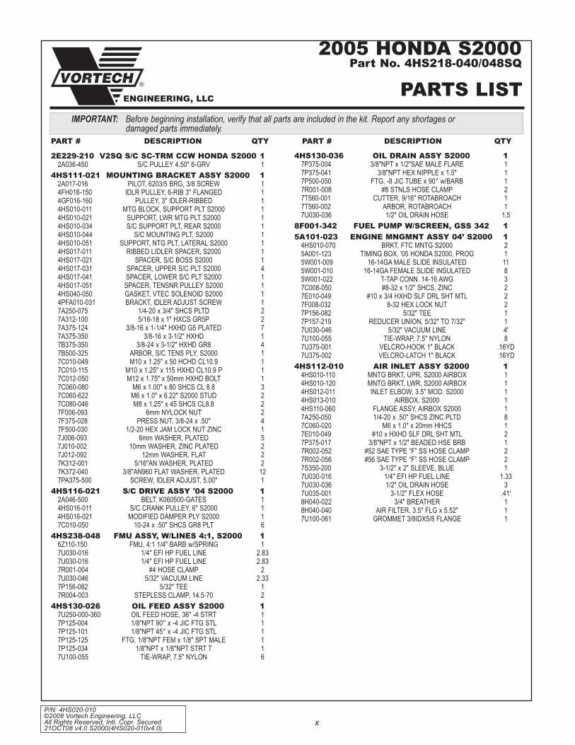
PARTS LIST - 2005 HONDA S2000 . . . . . . . . . . . . . . . . . . . . . . . . . . . . . . . . . . . . . . . . . . . . . . . x
PARTS LIST - 2007 HONDA S2000 (Internally Lubricated) . . . . . . . . . . . . . . . . . . . . . . . . . . . . xii
1. PREPARATION/REMOVAL . . . . . . . . . . . . . . . . . . . . . . . . . . . . . . . . . . . . . . . . . . . . . . . . . . 1
2. OIL FEED (2000-2005 Models only) . . . . . . . . . . . . . . . . . . . . . . . . . . . . . . . . . . . . . . . . . . . 3
3. OIL DRAIN (2000-2005 Models only) . . . . . . . . . . . . . . . . . . . . . . . . . . . . . . . . . . . . . . . . . . 4
4. CRANK DAMPER PULLEY INSTALLATION. . . . . . . . . . . . . . . . . . . . . . . . . . . . . . . . . . . . . 5
5. FUEL MANAGEMENT UNIT (2000-2005 Models only) . . . . . . . . . . . . . . . . . . . . . . . . . . . . 7
6. FUEL PUMP REPLACEMENT (2000-2005 Models only) . . . . . . . . . . . . . . . . . . . . . . . . . . 10
7. FUEL RAIL/REGULATOR MODIFICATIONS (2004, 2005 Models Only) . . . . . . . . . . . . . 11
8. SUPERCHARGER MOUNTING BRACKET/PLATE INSTALLATION . . . . . . . . . . . . . . . . . 12
9. FUEL INJECTOR REPLACEMENT (2007 MODELS ONLY) . . . . . . . . . . . . . . . . . . . . . . . 24
10. SUPPLEMENTARY FUEL INJECTOR INSTALLATION (2004, 2005 Models Only) . . . . . 25
11. SUPERCHARGER BELT TENSIONER ADJUSTMENT . . . . . . . . . . . . . . . . . . . . . . . . . . . 26
12. AIR PUMP INLET HOSE MODIFICATION (2000-2005 Models only). . . . . . . . . . . . . . . . . 26
13. CHARGE AIR COOLER INSTALLATION . . . . . . . . . . . . . . . . . . . . . . . . . . . . . . . . . . . . . . 27
14. AIR INLET DUCT INSTALLATION . . . . . . . . . . . . . . . . . . . . . . . . . . . . . . . . . . . . . . . . . . . 31
15. HOSE ATTACHMENTS/EXTENSIONS. . . . . . . . . . . . . . . . . . . . . . . . . . . . . . . . . . . . . . . . 32
16. ELECTRONIC CONTROL BOX INSTALLATION (2000-2005 MODELS ONLY) . . . . . . . . 33
17. ELECTRONIC CONTROL BOX INSTALLATION (2007 MODELS ONLY) . . . . . . . . . . . . . 37
18. FINAL CHECK. . . . . . . . . . . . . . . . . . . . . . . . . . . . . . . . . . . . . . . . . . . . . . . . . . . . . . . . . . . 39

P/N: 4HS020-010 ©2008 Vortech Engineering, LLC
All Rights Reserved, Intl. Copr. Secured 21OCT08 v4.0 S2000(4HS020-010v4.0)
v
2000-2008HONDA S2000
Installation InstructionsCongratulations on selecting the best performing and best backed automotive
supercharger available today... the VORTECH® Supercharger!
Before beginning this installation, please read through this entire instruction booklet and the Street Supercharger System Owner's Manual which includes the Automotive Limited Warranties Program and the Warranty Registration form.Vortech supercharger systems are performance improving devices. In most cases, increases in torque of 30-35% and horsepower of 35-45% can be expected with the boost levels specified by Vortech Engineering. This product is intended for use on healthy, well maintained engines. Installation on a worn-out or damaged engine is not recommended and may result in failure of the engine as well as the supercharger. Vortech Engineering is not responsible for engine damage.Installation on new vehicles will not harm or adversely affect the break-in period so long as factory break-in procedures are followed.For best performance and continued durability, please take note of the following key points:
1. Use only premium grade fuel 91 octane or higher (R+M/2).2. The engine must have stock compression ratio.3. If the engine has been modified in any way, check with Vortech prior to using this product.4. Always listen for any sign of detonation (pinging) and discontinue hard use (no boost) until problem is
resolved.5. Perform an oil and filter change upon completion of this installation and prior to test driving your vehicle.
Thereafter, always use a high grade engine oil or a high quality synthetic, and change the oil and filter every 3,000 miles or less. Never attempt to extend the oil change interval beyond 3,000 miles, regard-less of oil manufacturer's claims as potential damage to the supercharger may result.
6. Before beginning installation, replace all spark plugs that are older than 2 years or 20,000 miles with original heat range plugs as specified by the manufacturer and retard timing from factory specifications (follow the procedures indicated within the factory repair manual and/or as indicated on the factory underhood emissions tag). Do not use platinum spark plugs unless they are original equipment. Change spark plugs every at least 15,000 miles and spark plug wires at least every 50,000 miles.
TOOL & SUPPLY REQUIREMENTS:• Factory Repair Manual• 3/8" Socket and Drive Set: SAE & Metric• 3/8” Swivel Head Ratchet• 1/2" Socket and Drive Set: SAE & Metric• 3/8" NPT Tap and Handle• Adjustable Wrench • Open End Wrenches: SAE & Metric • Center Punch• 5 Quarts SH/CF Rated Quality Engine Oil• Oil Filter and Wrench• Flat #2 Screwdriver• Phillips #2 Screwdriver• Heavy Grease• Silicone Sealer• Drill Motor • 1/8", 3/16" Drill Bits• Hex Key Wrench Set• Wire Strippers and Crimpers• Utility Knife• Hand Held Grinder• Blue Loctite• 07JAB-001020A (Damper Tool) Available at Honda Dealer• 07NAB-001040A (Damper Tool) Available at Honda Dealer• Honda Bond (Sealer) Available at Honda Dealer
If your vehicle has in excess of 20,000 miles since its last spark plug change, then you will also need:• Spark Plug Socket• New Spark Plugs

P/N: 4HS020-010 ©2008 Vortech Engineering, LLC All Rights Reserved, Intl. Copr. Secured 21OCT08 v4.0 S2000(4HS020-010v4.0)
vi
®
ENGINEERING, LLC
2E229-180 SUPERCHARGER ASSY 14HS111-021 MOUNTING BRACkET ASSY 1
4HS010-011 Mtg. plate block 14HS010-021 lower S/c plate Spacer 14HS010-034 Upper S/c SUpport plate 14HS010-044 S/c MoUnting plate 14HS010-051 lateral S/c MoUnting plate SUpport 17a250-075 1/4-20 x .75" SHcS 24pFa010-031 tenSioner adj. Screw locator 17pa375-500 tenSioner Screw 17b500-325 tenSioner arbor 14HS017-051 tenSioner Spacer 14HS017-011 ribbed idler Spacer 14HS017-031 Upper S/c plate Spacer 44HS017-021 12mm S/c boSS Spacer 14HS017-041 S/c plate Spacer (to Stock idler) 17F375-028 3/8-24 preSS nUtS 47b375-350 3/8-24 x 3.50" 47c010-115 M10 x 1.25" x 115 bolt 17j010-002 M10 waSHer (.080" tHk.) 27c060-622 M6 x 1.00" x 158 StUd 27c010-049 M10 x 1.25" x 50 bolt 17c060-080 M6 x 1.00" x 80 bolt 37c012-050 M12 x 1.75" x 50 bolt 17a375-124 3/8-16 x 1.25" 77a375-350 3/8-16 x 3.50" 17k375-040 3/8"an waSHer 127j006-093 M6 waSHer 57F006-093 M6 nUtS 27j012-092 M12 waSHer 27F500-030 1/2-20 jaM lock nUt 12a017-016 3/8"id bearing pilot (6203 brg) 14gF016-160 ribbed 3" idler 14FH016-150 SMootH 3" idler 14HS040-050 V-tecH Solenoid gaSket 17c080-046 M8 x 1.25" x 45 SHcS 27a312-100 5/16-18 x 1.0" HXHd 27k312-001 5/16"an waSHer 2
4HS116-011 S/C DRIVE ASSEMBLY 14HS016-011 crank pUlley 17c010-050 10-24 x .50" SHcS gr8 64HS016-021 ModiFied daMper pUlley 12a046-510 S/c driVe belt 1
4HS238-068 FMU ASSEMBLY 16Z110-144 FMU aSSy 17U030-016 1/4" FUel HoSe-FMU “in” 34"7U030-016 1/4" FUel HoSe-FMU “oUt” 28"7r001-004 #4 HoSe claMp 27U030-046 5/32" VacUUM HoSe 28"7p156-082 5/32" tee 17r004-003 14.5 StepleSS claMp 2
4HS130-036 OIL DRAIN ASSEMBLY 17U030-036 oil drain HoSe 18"7r001-008 #8 claMp 27p375-004 3/8" nptF x -8 Sae Flare Fitting 17p500-050 Ftg,-8 jic tUbe x 90° w/barb 17t560-001 cUtter, 9/16" rotabroacH 17t560-002 arbor, 9/16" rotabroacH 17p375-041 3/8"npt x 1.5" HeX nipple 1
4HS130-026 OIL FEED ASSEMBLY 17U250-000-360 oil Feed HoSe 17p125-004 #4 jic x 90° x 1/8"npt Ftg 17p125-101 #4 jic x 45° x 1/8"npt Ftg 17p125-125 1/8"npt FeM x 1/8" bSpt 17p125-034 1/8" Street tee 17U100-055 6" Zip-tie 6
4HS112-010 AIR INLET ASSEMBLY 18H040-022 3/4" breatHer Fitting 18H040-040 3.5" air Filter 17S350-200 3.5" x 2" SleeVe 17r002-056 #56 claMpS 27r002-052 #52 claMp 27U030-016 1/4" coolant HoSe 16"4HS013-010 air boX 17a250-050 1/4-20 x .5" SHcS 87U035-001 3.5" FleX HoSe 5"7U030-036 oil drain HoSe 36"4HS110-060 air Filter MoUnting Flange aSSy 14HS012-011 3.5" plaStic inlet elbow 17p375-017 3/8"npt x 1/2" beaded HoSe barb 17e010-049 #10 SHeetMetal Screw 27c060-020 M6 x 1.0" x 20 HXHd 14HS010-110 air boX MoUnting tab, Upper 14HS010-120 air boX MoUnting tab, lower 17U100-061 groMMet, 3/8 id 5/8 Flange 1
8N401-010 POWERCOOLER/DISCH. ASSY 17a250-050 1/4-20 x .5" SHcS 28H040-175 race bypaSS Filter 18n055-050 SUrge tank cap 17S275-200 2.75" SleeVe x 2" SleeVe 17S275-300 2.75" SleeVe x 3" SleeVe 17r002-044 #44 claMp 47p500-026 3/4" HoSe barb x 1/2"npt x 90° FtgS 27U030-046 5/32" VacUUM HoSe 24"7p156-082 5/32" tee 17U030-030 1/4" VacUUM HoSe 36"7p250-033 5/32" - 1/4" redUcer 1008341 powercooler decal 18n301-140 welded cooler core aSSy 1
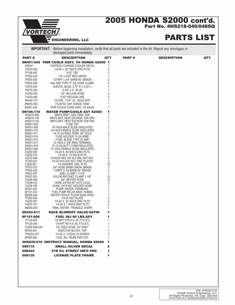
Before beginning installation, verify that all parts are included in the kit. Report any shortages or damaged parts immediately.
PART # DESCRIPTION QTY PART # DESCRIPTION QTY
2000-2003 HONDA S2000Part No. 4HS218-010SQ/-018SQ
PARTS LIST

P/N: 4HS020-010 ©2008 Vortech Engineering, LLC
All Rights Reserved, Intl. Copr. Secured 21OCT08 v4.0 S2000(4HS020-010v4.0)
vii
8N106-110 WATER COOLER ASSY 14HS010-080 Mntg brkt, H2o tank, S2k 14HS010-130 Mntg bkt, Heat eXcHgr, S2k drV 14HS010-140 Mntg bkt, Heat eXcHgr, S2k paS 15w001-002 FUSe tap 15w001-009 16-14ga Male Slide inSUlated 15w001-010 16-14ga FeMale Slide inSUlated 15w001-011 16-14 ga ring terM .26" Hole 25w001-014 FUSe Holder 10 ga wire 15w001-015 FUSe, blade type 20 aMp 15w001-017 12-10ga X 3/8" ring terMinal 15w001-019 10-12 ga bUtt conn inSUlated 15w001-040 12-10ga FeMale Slide inSUlated 17a250-050 1/4-20 X .50 SHcS Zinc pltd 27a250-075 1/4-20 X .75 SHcS pltd 37e010-049 #10X3/4 HeX Hd SlF drl SHt Mtl 67F250-021 1/4-20 nylock nUt Zinc plated 37j250-001 1/4 waSHer, Sae, pltd 167p375-075 3/4" HoSe barb Union, braSS 27p500-026 1/2npt X 3/4 barb 90° braSS 27r003-027 adel claMp,1-11/16" 17r007-001 nylon ratcHet claMp 1-1/8" 127U038-000 3/4" Heater HoSe 127U038-012 HoSe,3/4"dia 90°,4X12 legS 27U038-150 HoSe, 3/4"X150° Molded HoSe 18F001-402 pUMp, water, pierbUrg 18F101-310 FUel pUMp relay aSSy, Honda 18n006-020 water coolr, Fldyn dUal paSS 17F250-040 1/4-20 nUt plate 27a250-051 1/4-20 X .50 HHcS Zinc pltd 47a250-101 1/4-20 X 1 HHcS Zinc pltd 28n055-030 tank, water, triangle SHape 1
5A201-001 ELECTRONICS UPGRADE ASSY 4HS010-070 brkt, Ftc Mntg S2k 25a001-051 tiMing control boX 15a101-020 Map claMp 15w001-009 16-14ga Male Slide inSUlated 115w001-010 16-14ga FeMale Slide inSUlated 85w001-022 t-tap conn, 14-16 awg 37c008-050 8-32 x 1/2" SHcS 27e010-049 #10 SHeet Metal Screw 27F008-032 8-32 nylock nUt 27p156-082 5/32" tee, braSS 17p157-219 redUcer Union, 5/32" to 7/32" 17U030-046 5/32" VaccUM line 4'7U100-055 tie-wrap, 6" nylon 87U375-001 Velcro-Hook 1" black .166yd7U375-002 Velcro-latcH 1" black .166yd
8F001-342 FUEL PUMP ASSY. 18D204-011 RACE BLOWOFF VALVE 14HS020-010 INSTRUCTION MANUAL 1008110 DECALS 2008444 S/C OWNERS PACkET 1008130 LIC. PLATE FRAME, VORTECH 1
PART # DESCRIPTION QTY
IMPORTANT: Before beginning installation, verify that all parts are included in the kit. Report any shortages or damaged parts immediately.
2000-2003 HONDA S2000 cont'd.Part No. 4HS218-010SQ/-018SQ
PARTS LIST®
ENGINEERING, LLC

P/N: 4HS020-010 ©2008 Vortech Engineering, LLC All Rights Reserved, Intl. Copr. Secured 21OCT08 v4.0 S2000(4HS020-010v4.0)
viii
2E229-210 V2SQ S/C SC-TRM CCW HONDA S2000 12a036-450 S/c pUlley 4.50" 6-grV 1
4HS111-021 MOUNTING BRACkET ASSY S2000 12a017-016 pilot, 6203/5 brg, 3/8" Screw 14FH016-150 idlr pUlley, 6-rib 3" Flanged 14gF016-160 pUlley, 3" idler-ribbed 14HS010-011 Mtg block, SUpport plt S2000 14HS010-021 SUpport, lwr Mtg plt S2000 14HS010-034 S/c SUpport plt, rear S2000 14HS010-044 S/c MoUnting plt, S2000 14HS010-051 SUpport, Mtg plt, lateral S2000 14HS017-011 ribbed idler Spacer, S2000 14HS017-021 Spacer, S/c boSS S2000 14HS017-031 Spacer, Upper S/c plt S2000 44HS017-041 Spacer, lower S/c plt S2000 14HS017-051 Spacer, tenSnr pUlley S2000 14HS040-050 gaSket, Vtec Solenoid S2000 14pFa010-031 brackt, idler adjUSt Screw 17a250-075 1/4-20 x 3/4" SHcS pltd 27a312-100 5/16-18 x 1" HXcS gr5p 27a375-124 3/8-16 x 1-1/4" HXHd g5 plated 77a375-350 3/8-16 x 3-1/2" HXHd 17b375-350 3/8-24 x 3-1/2" HXHd gr8 47b500-325 arbor, S/c tenS ply, S2000 17c010-049 M10 x 1.25" 50 HcHd cl10.9 17c010-115 M10 x 1.25" x 115 HXHd cl10.9 p 17c012-050 M12 x 1.75" x 50mm HXHd bolt 17c060-080 M6 x 1.00" x 80 SHcS cl 8.8 37c060-622 M6 x 1.0" x 6.22" S2000 StUd 27c080-046 M8 x 1.25" x 45 SHcS cl8.8 27F006-093 6mm nylock nUt 27F375-028 preSS nUt, 3/8-24 x .50" 47F500-030 1/2-20 HeX jaM lock nUt Zinc 17j006-093 6mm waSHer, plated 57j010-002 10mm waSHer, Zinc plated 27j012-092 12mm waSHer, Flat 27k312-001 5/16"an waSHer, plated 27k372-040 3/8"an960 Flat waSHer, plated 127pa375-500 Screw, idler adjUSt, 5.00" 1
4HS116-021 S/C DRIVE ASSY '04 S2000 12a046-500 belt, k060500-gateS 14HS016-011 S/c crank pUlley, 6" S2000 14HS016-021 ModiFied daMper ply S2000 17c010-050 10-24 x .50" SHcS gr8 plt 6
4HS238-048 FMU ASSY, W/LINES 4:1, S2000 16Z110-150 FMU, 4:1 1/4" barb w/Spring 16Z050-151 FMU waSHer, 4:1/38lb. plated 16Z070-020 FMU 4:1 ring Spacer 16Z090-010 Spring, FMU gM 4.3 17c010-050 10-24 x .50" SHcS gr8 plt 67c010-075 10-24 x 3/4" SHcS gr5 Zinc 47c024-025 10-24 x 1/4" pHill Hd 37e010-046 #8 x 3/4" SHeet Metal 27p125-025 1/8"npt x 5/32" HoSe 90° 17p125-036 1/8"npt-Strt 1/4" barb 17p125-037 1/8"npt x 90° to 1/4" barb 17U100-030 o-ring, FMU 1
PART # DESCRIPTION QTY PART # DESCRIPTION QTY7U030-016 1/4" eFi Hp FUel line 27U030-016 1/4" eFi Hp FUel line 27r001-004 #4 HoSe claMp 27U030-046 5/32" VacUUM line 27p156-082 5/32" tee 17r004-003 StepleSS claMp, 14.5-70 2
4HS130-026 OIL FEED ASSY S2000 17U250-000-360 oil Feed HoSe, 36" -4 Strt 17p125-004 1/8"npt 90° x -4 jic Ftg Stl 17p125-101 1/8"npt 45° x -4 jic Ftg Stl 17p125-125 Ftg, 1/8"npt FeM x 1/8" Spt Male 17p125-034 1/8"npt x 1/8"npt Strt t 17U100-055 tie-wrap, 7.5" nylon 6
4HS130-036 OIL DRAIN ASSY S2000 17p375-004 3/8"npt x 1/2"Sae Male Flare 17p375-041 3/8"npt HeX nipple x 1.5" 17p500-050 Ftg, -8 jic tUbe x 90° w/barb 17r001-008 #8 StnlS HoSe claMp 27t560-001 cUtter, 9/16" rotabroacH 17t560-002 arbor, rotabroacH 17U030-036 1/2" oil drain HoSe 1
8F001-342 FUEL PUMP W/SCREEN, GSS 342 15A101-021 ENGINE MNGMNT ASSY '04 S2000 1
4HS010-070 brkt, Ftc Mntg S2000 25a001-121 tiMing boX, '04 Honda S2000, prog 15w001-009 16-14ga Male Slide inSUlated 115w001-010 16-14ga FeMale Slide inSUlated 85w001-022 t-tap conn. 14-16 awg 37c008-050 #8-32 x 1/2" SHcS, Zinc 27e010-049 #10 x 3/4" HXHd SlF drl SHt Mtl 27F008-032 8-32 HeX lock nUt 27p156-082 5/32" tee 17p157-219 redUcer Union, 5/32" to 7/32" 17U030-046 5/32" VacUUM line 4'7U100-055 tie-wrap, 7.5" nylon 87U375-001 Velcro-Hook 1" black .16yd7U375-002 Velcro-latcH 1" black .16yd
4HS112-010 AIR INLET ASSY S2000 14HS010-110 Mntg brkt, Upr, S2000 airboX 14HS010-120 Mntg brkt, lwr, S2000 airboX 14HS012-011 inlet elbow, 3.5" Mod. S2000 14HS013-010 airboX, S2000 14HS110-060 Flange aSSy, airboX S2000 17a250-050 1/4-20 x .50 SHcS Zinc pltd 87c060-020 M6 x 1.0" x 20mm HHcS 17e010-049 #10 x HXHd SlF drl SHt Mtl 27p375-017 3/8"npt x 1/2" beaded HSe brb 17r002-052 #52 Sae type “F” SS HoSe claMp 27r002-056 #56 Sae type “F” SS HoSe claMp 27S350-200 3-1/2" x 2" SleeVe, blUe 17U030-016 1/4" eFi Hp FUel line 17U030-036 1/2" oil drain HoSe 37U035-001 3-1/2" FleX HoSe .41'8H040-022 3/4" breatHer 18H040-040 air Filter, 3.5" Flg x 5.52" 1
IMPORTANT: Before beginning installation, verify that all parts are included in the kit. Report any shortages or damaged parts immediately.
2004 HONDA S2000Part No. 4HS218-020/028SQ
PARTS LIST®
ENGINEERING, LLC

P/N: 4HS020-010 ©2008 Vortech Engineering, LLC
All Rights Reserved, Intl. Copr. Secured 21OCT08 v4.0 S2000(4HS020-010v4.0)
ix
8N401-040 PWR COOLR ASSY, '04 HONDA S2000 1008341 VortecH cHarge cooler decal 17a250-050 1/4-20 x .50" SHcS Zinc pltd 27p156-082 5/32" tee 17p250-033 1/4" x 5/32" red.Union 17p500-026 1/2"npt x 3/4" barb 90° braSS 27r002-044 #44 Sae type “F” SS HoSe claMp 47S275-200 SleeVe, blUe, 2.75" d x 2.00" l 17S275-300 2-3/4" x 3", blUe 17U030-030 1/4" VacUUM HoSe 37U030-046 5/32" VacUUM line 28H040-175 Filter, 1-3/4" i.d., race bypaSS 18n055-050 plaStic cap, SUrge tank 18n301-240 pwr coolr core aSSy, '04 S2000 1
8N106-110 WATER PUMP/COOLR ASY S2000 14HS010-080 Mntg brkt, H2o tank, S2k 14HS010-130 Mntg bkt, Heat eXcHgr, S2k drV 14HS010-140 Mntg bkt, Heat eXcHgr, S2k paS 15w001-002 FUSe tap 15w001-009 16-14ga Male Slide inSUlated 15w001-010 16-14ga FeMale Slide inSUlated 15w001-011 16-14 ga ring terM .26" Hole 25w001-014 FUSe Holder 10 ga wire 15w001-015 FUSe, blade type 20 aMp 15w001-017 12-10ga X 3/8" ring terMinal 15w001-019 10-12 ga bUtt conn inSUlated 15w001-040 12-10ga FeMale Slide inSUlated 17a250-050 1/4-20 X .50 SHcS Zinc pltd 27a250-075 1/4-20 X .75 SHcS pltd 37e010-049 #10X3/4 HeX Hd SlF drl SHt Mtl 67F250-021 1/4-20 nylock nUt Zinc plated 37j250-001 1/4 waSHer, Sae, pltd 167p375-075 3/4" HoSe barb Union, braSS 27p500-026 1/2npt X 3/4 barb 90° braSS 27r003-027 adel claMp,1-11/16" 17r007-001 nylon ratcHet claMp 1-1/8" 127U038-000 3/4" Heater HoSe 127U038-012 HoSe,3/4"dia 90°,4X12 legS 27U038-150 HoSe, 3/4"X150° Molded HoSe 18F001-402 pUMp, water, pierbUrg 18F101-310 FUel pUMp relay aSSy, Honda 18n006-020 water coolr, Fldyn dUal paSS 17F250-040 1/4-20 nUt plate 27a250-051 1/4-20 X .50 HHcS Zinc pltd 47a250-101 1/4-20 X 1 HHcS Zinc pltd 28n055-030 tank, water, triangle SHape 1
8D204-011 RACE BLOWOFF VALVE-SATIN 17a250-074 1/4-20 x .75" HHcS pltd 27a312-126 5/16-18 x 1.25" Set Scrw oVal p 17F312-022 5/16-18 jaM nUt, StainleSS 17j006-093 6mm waSHer, plated 27p125-109 Ftg, 1/8"npt - 1/4" barb, al 17U100-086 Snap ring, coMpact bypaSS 18d003-080 retainer, Spring 18d004-023 coVer, race bypaSS-blUe 18d004-053 gaSket, Mtg Flng, M.F. race bypaSS 18d004-083 Spring, MFrb, 12" Hg 18d104-042 MFrb body aSSy Satin 17c011-200 10-32 SHcS x 2" Zinc plate 17F010-030 10-32 tHin nylock nUt SSt 1
PART # DESCRIPTION QTY PART # DESCRIPTION QTY7p125-020 breatHer, SFMU 17U100-049 o-ring, coMp. bypaSS 18d004-031 ValVe, coMpact bypaSS anodiZed 18d004-061 piSton, coMpact bypaSS MacHined 18d004-091 diapHraM, coMpact bypaSS 18d004-141 SleeVe, coMpact bypaSS MacHined 18d104-042r Mini bypaSS gUide aSSy 1
4HS020-010 INSTRUCT MANUAL, HONDA S2000 18F101-006 FUEL INj 55 LBS.ASY 1
7p125-005 1/8 npt Str.X-4 jic Ftg Stl 17p125-004 1/8 npt 90°X-4 jic Ftg Stl 17U250-090-240 oil Feed HoSe, 24"-4X90° 18F003-081 injector block, top 17pa250-275 1/4-20 X .312dX2.75 Screw 28F060-055 FUel inj, 55lbS rail Style, Hi 1
008110 SMALL SILVER DECAL 2008444 3YR S/L STREET INFO PkG 1008130 LICENSE PLATE FRAME 1
IMPORTANT: Before beginning installation, verify that all parts are included in the kit. Report any shortages or damaged parts immediately.
2004 HONDA S2000 cont'd.Part No. 4HS218-020/028SQ
PARTS LIST®
ENGINEERING, LLC
P/N: 4HS020-010 ©2008 Vortech Engineering, LLC All Rights Reserved, Intl. Copr. Secured 21OCT08 v4.0 S2000(4HS020-010v4.0)
x
2E229-210 V2SQ S/C SC-TRM CCW HONDA S2000 12a036-450 S/c pUlley 4.50" 6-grV 1
4HS111-021 MOUNTING BRACkET ASSY S2000 12a017-016 pilot, 6203/5 brg, 3/8 Screw 14FH016-150 idlr pUlley, 6-rib 3" Flanged 14gF016-160 pUlley, 3" idler-ribbed 14HS010-011 Mtg block, SUpport plt S2000 14HS010-021 SUpport, lwr Mtg plt S2000 14HS010-034 S/c SUpport plt, rear S2000 14HS010-044 S/c MoUnting plt, S2000 14HS010-051 SUpport, ntg plt, lateral S2000 14HS017-011 ribbed lidler Spacer, S2000 14HS017-021 Spacer, S/c boSS S2000 14HS017-031 Spacer, Upper S/c plt S2000 44HS017-041 Spacer, lower S/c plt S2000 14HS017-051 Spacer, tenSnr pUlley S2000 14HS040-050 gaSket, Vtec Solenoid S2000 14pFa010-031 brackt, idler adjUSt Screw 17a250-075 1/4-20 x 3/4" SHcS pltd 27a312-100 5/16-18 x 1" HXcS gr5p 27a375-124 3/8-16 x 1-1/4" HXHd g5 plated 77a375-350 3/8-16 x 3-1/2" HXHd 17b375-350 3/8-24 x 3-1/2" HXHd gr8 47b500-325 arbor, S/c tenS ply, S2000 17c010-049 M10 x 1.25" x 50 HcHd cl10.9 17c010-115 M10 x 1.25" x 115 HXHd cl10.9 p 17c012-050 M12 x 1.75" x 50mm HXHd bolt 17c060-080 M6 x 1.00" x 80 SHcS cl 8.8 37c060-622 M6 x 1.0" x 6.22" S2000 StUd 27c080-046 M8 x 1.25" x 45 SHcS cl8.8 27F006-093 6mm nylock nUt 27F375-028 preSS nUt, 3/8-24 x .50" 47F500-030 1/2-20 HeX jaM lock nUt Zinc 17j006-093 6mm waSHer, plated 57j010-002 10mm waSHer, Zinc plated 27j012-092 12mm waSHer, Flat 27k312-001 5/16"an waSHer, plated 27k372-040 3/8"an960 Flat waSHer, plated 127pa375-500 Screw, idler adjUSt, 5.00" 1
4HS116-021 S/C DRIVE ASSY '04 S2000 12a046-500 belt, k060500-gateS 14HS016-011 S/c crank pUlley, 6" S2000 14HS016-021 ModiFied daMper ply S2000 17c010-050 10-24 x .50" SHcS gr8 plt 6
4HS238-048 FMU ASSY, W/LINES 4:1, S2000 16Z110-150 FMU, 4:1 1/4" barb w/Spring 17U030-016 1/4" eFi Hp FUel line 2.837U030-016 1/4" eFi Hp FUel line 2.837r001-004 #4 HoSe claMp 27U030-046 5/32" VacUUM line 2.337p156-082 5/32" tee 17r004-003 StepleSS claMp, 14.5-70 2
4HS130-026 OIL FEED ASSY S2000 17U250-000-360 oil Feed HoSe, 36" -4 Strt 17p125-004 1/8"npt 90° x -4 jic Ftg Stl 17p125-101 1/8"npt 45° x -4 jic Ftg Stl 17p125-125 Ftg, 1/8"npt FeM x 1/8" Spt Male 17p125-034 1/8"npt x 1/8"npt Strt t 17U100-055 tie-wrap, 7.5" nylon 6
PART # DESCRIPTION QTY PART # DESCRIPTION QTY
4HS130-036 OIL DRAIN ASSY S2000 17p375-004 3/8"npt x 1/2"Sae Male Flare 17p375-041 3/8"npt HeX nipple x 1.5" 17p500-050 Ftg, -8 jic tUbe x 90° w/barb 17r001-008 #8 StnlS HoSe claMp 27t560-001 cUtter, 9/16" rotabroacH 17t560-002 arbor, rotabroacH 17U030-036 1/2" oil drain HoSe 1.5
8F001-342 FUEL PUMP W/SCREEN, GSS 342 15A101-023 ENGINE MNGMNT ASSY 04’ S2000 1
4HS010-070 brkt, Ftc Mntg S2000 25a001-123 tiMing boX, '05 Honda S2000, prog 15w001-009 16-14ga Male Slide inSUlated 115w001-010 16-14ga FeMale Slide inSUlated 85w001-022 t-tap conn. 14-16 awg 37c008-050 #8-32 x 1/2" SHcS, Zinc 27e010-049 #10 x 3/4 HXHd SlF drl SHt Mtl 27F008-032 8-32 HeX lock nUt 27p156-082 5/32" tee 17p157-219 redUcer Union, 5/32" to 7/32" 17U030-046 5/32" VacUUM line 4'7U100-055 tie-wrap, 7.5" nylon 87U375-001 Velcro-Hook 1" black .16yd7U375-002 Velcro-latcH 1" black .16yd
4HS112-010 AIR INLET ASSY S2000 14HS010-110 Mntg brkt, Upr, S2000 airboX 14HS010-120 Mntg brkt, lwr, S2000 airboX 14HS012-011 inlet elbow, 3.5" Mod. S2000 14HS013-010 airboX, S2000 14HS110-060 Flange aSSy, airboX S2000 17a250-050 1/4-20 x .50" SHcS Zinc pltd 87c060-020 M6 x 1.0" x 20mm HHcS 17e010-049 #10 x HXHd SlF drl SHt Mtl 27p375-017 3/8"npt x 1/2" beaded HSe brb 17r002-052 #52 Sae type “F” SS HoSe claMp 27r002-056 #56 Sae type “F” SS HoSe claMp 27S350-200 3-1/2" x 2" SleeVe, blUe 17U030-016 1/4" eFi Hp FUel line 1.337U030-036 1/2" oil drain HoSe 37U035-001 3-1/2" FleX HoSe .41'8H040-022 3/4" breatHer 18H040-040 air Filter, 3.5" Flg x 5.52" 17U100-061 groMMet 3/8idX5/8 Flange 1
IMPORTANT: Before beginning installation, verify that all parts are included in the kit. Report any shortages or damaged parts immediately.
2005 HONDA S2000Part No. 4HS218-040/048SQ
PARTS LIST®
ENGINEERING, LLC
P/N: 4HS020-010 ©2008 Vortech Engineering, LLC
All Rights Reserved, Intl. Copr. Secured 21OCT08 v4.0 S2000(4HS020-010v4.0)
xi
8N401-040 PWR COOLR ASSY, '04 HONDA S2000 1008341 VortecH cHarge cooler decal 17a250-050 1/4-20 x .50" SHcS Zinc pltd 27p156-082 5/32" tee 17p250-033 1/4" x 5/32" red.Union 17p500-026 1/2"npt x 3/4" barb 90° braSS 27r002-044 #44 Sae type “F” SS HoSe claMp 47S275-200 SleeVe, blUe, 2.75" d x 2.00" l 17S275-300 2-3/4" x 3", blUe 17U030-030 1/4" VacUUM HoSe 37U030-046 5/32" VacUUM line 28H040-175 Filter, 1-3/4" i.d., race byp 18n055-050 plaStic cap, SUrge tank 18n301-240 pwr coolr core aSSy, '04 S2000 1
8N106-110 WATER PUMP/COOLR ASY S2000 14HS010-080 Mntg brkt, H2o tank, S2k 14HS010-130 Mntg bkt, Heat eXcHgr, S2k drV 14HS010-140 Mntg bkt, Heat eXcHgr, S2k paS 15w001-002 FUSe tap 15w001-009 16-14ga Male Slide inSUlated 15w001-010 16-14ga FeMale Slide inSUlated 15w001-011 16-14 ga ring terM .26" Hole 25w001-014 FUSe Holder 10 ga wire 15w001-015 FUSe, blade type 20 aMp 15w001-017 12-10ga X 3/8" ring terMinal 15w001-019 10-12 ga bUtt conn inSUlated 15w001-040 12-10ga FeMale Slide inSUlated 17a250-050 1/4-20 X .50 SHcS Zinc pltd 27a250-075 1/4-20 X .75 SHcS pltd 37e010-049 #10X3/4 HeX Hd SlF drl SHt Mtl 67F250-021 1/4-20 nylock nUt Zinc plated 37j250-001 1/4 waSHer, Sae, pltd 167p375-075 3/4" HoSe barb Union, braSS 27p500-026 1/2npt X 3/4 barb 90° braSS 27r003-027 adel claMp,1-11/16" 17r007-001 nylon ratcHet claMp 1-1/8" 127U038-000 3/4" Heater HoSe 127U038-012 HoSe,3/4"dia 90°,4X12 legS 27U038-150 HoSe, 3/4"X150° Molded HoSe 18F001-402 pUMp, water, pierbUrg 18F101-310 FUel pUMp relay aSSy, Honda 18n006-020 water coolr, Fldyn dUal paSS 17F250-040 1/4-20 nUt plate 27a250-051 1/4-20 X .50 HHcS Zinc pltd 47a250-101 1/4-20 X 1 HHcS Zinc pltd 28n055-030 tank, water, triangle SHape 1
8D204-011 RACE BLOWOFF VALVE-SATIN 18F101-008 FUEL INj 60 LBS.ASY 1
7p125-005 1/8 npt Str.X-4 jic Ftg Stl 17p125-004 1/8 npt 90°X-4 jic Ftg Stl 17U250-090-240 oil Feed HoSe, 24"-4X90° 18F003-081 injector block, top 17pa250-275 1/4-20 X .312dX2.75 Screw 28F060-060 FUel inj, 60lbS pen Std 1
4HS020-010 INSTRUCT MANUAL, HONDA S2000 1008110 SMALL SILVER DECAL 2008444 3YR S/L STREET INFO PkG 1008130 LICENSE PLATE FRAME 1
PART # DESCRIPTION QTY PART # DESCRIPTION QTY
IMPORTANT: Before beginning installation, verify that all parts are included in the kit. Report any shortages or damaged parts immediately.
PARTS LIST®
ENGINEERING, LLC
2005 HONDA S2000 cont'd.Part No. 4HS218-040/048SQ

P/N: 4HS020-010 ©2008 Vortech Engineering, LLC All Rights Reserved, Intl. Copr. Secured 21OCT08 v4.0 S2000(4HS020-010v4.0)
xii
2F339-010 V3 S/C SC-TRM CCW HONDA S2k 1
4HS111-021 MOUNTING BRkT ASSY S2000 12a017-016 pilot, 6203/5 brg, 3/8 Screw 14FH016-150 idler pUly, 6rib 3" Flangd 14gF016-160 pUlley, 3" idler-ribbed 14HS010-011 Mtg block, SUpport plt S2000 14HS010-021 SUpport, lwr Mtg plt S2000 14HS010-034 S/c SUpport plt, rear S2000 14HS010-044 S/c MoUnting plt, S2000 14HS010-051 SUprt, Mtg plt, lateral S200o 14HS017-011 ribbed idler Spacer, S2000 14HS017-021 Spacer, S/c boSS S2000 14HS017-031 Spacer, Upper S/c plt S2000 44HS017-041 Spacer, lower S/c plt S2000 14HS017-051 Spacer, tenSnr pUlley S2000 14HS040-050 gaSket, Vtec Solenoid S2000 14pFa010-031 brackt, idler adjUSt Screw 17a250-075 1/4-20 X .75 SHcS pltd 27a312-100 5/16-18 X 1 HHcS, gr5, plated 27a375-124 3/8-16 X 1-1/4 HHcS, g5, plate 77a375-350 3/8-16 X 3.5" HX Hd gr5 17b375-350 3/8-24 X 3-1/2" HXHd gr8 47b500-325 arbor, S/c tenS ply, S2000 17c010-049 M10 X 1.25 X 50 HXHd cl10.9 17c010-115 M10 X 1.25 X 115 HXHd cl10.9 p 17c012-050 M12 X 1.75 X 50MM HXHd bolt 17c060-080 M6 X 1.00 X 80 SHcS cl 12.9 37c060-622 M6 X 1.0 X 6.22" S2000 StUd 27c080-046 M8 X 1.25 X 45 SHcS cl8.8 27F006-093 6MM nylock nUt 27F375-028 preSS nUt, 3/8-24 X .50 47F500-030 1/2-20 HeX jaM lock nUt Zinc 17j006-093 6MM waSHer, plated 57j010-002 10MM waSHer, Zinc plated 27j012-092 12MM waSHer, Flat 27k312-001 5/16 an waSHer, plated 27k375-040 3/8 an960 Flat waSHr plated 127pa375-500 Screw, idler adjUSt, 5.00" 1
4HS116-021 S/C DRIVE ASSY 04' S2000 12a046-500 belt, k060500-gateS 14HS016-011 S/c crank pUlley, 6" S2000 14HS016-021 ModiFied daMper ply S2000 17c010-050 10-24 X .50 SHcS gr8 plt 6
8D204-011 RACE BLOWOFF VALVE-SATIN 1007060 inStr, race bypaSS/blowoFF 1008220 warning Sticker M.F. race bypa 18d004-053 gaSket,Mtg Flng,M.F. race bypa 1
8N106-110 WATER PUMP/COOLR ASY S2000 14HS010-080 Mntg brkt, H2o tank, S2k 14HS010-130 Mntg bkt, Heat eXcHgr, S2k drV 14HS010-140 Mntg bkt, Heat eXcHgr, S2k paS 15w001-002 FUSe tap 15w001-009 16-14ga Male Slide inSUlated 15w001-010 16-14ga FeMale Slide inSUlated 15w001-011 16-14 ga ring terM .26" Hole 25w001-014 FUSe Holder 10 ga wire 15w001-015 FUSe, blade type 20 aMp 15w001-017 12-10ga X 3/8" ring terMinal 15w001-019 10-12 ga bUtt conn inSUlated 15w001-040 12-10ga FeMale Slide inSUlated 17a250-050 1/4-20 X .50 SHcS Zinc pltd 27a250-075 1/4-20 X .75 SHcS pltd 37e010-049 #10X3/4 HeX Hd SlF drl SHt Mtl 67F250-021 1/4-20 nylock nUt Zinc plated 37j250-001 1/4 waSHer, Sae, pltd 167p375-075 3/4" HoSe barb Union, braSS 27p500-026 1/2npt X 3/4 barb 90° braSS 27r003-027 adel claMp,1-11/16" 1
7r007-001 nylon ratcHet claMp 1-1/8" 127U038-000 3/4" Heater HoSe 127U038-012 HoSe,3/4"dia 90°,4X12 legS 27U038-150 HoSe, 3/4"X150° Molded HoSe 18F001-402 pUMp, water, pierbUrg 18F101-310 FUel pUMp relay aSSy, Honda 18n006-020 water coolr, Fldyn dUal paSS 17F250-040 1/4-20 nUt plate 27a250-051 1/4-20 X .50 HHcS Zinc pltd 47a250-101 1/4-20 X 1 HHcS Zinc pltd 28n055-030 tank, water, triangle SHape 1
8F101-007 ASSY., FUEL INj., 55LB., 07 S2 17c060-030 M6 X 1.0 X 30MM, Flg Hd, plate 27c080-056 M8 X 1.25 X 55 HXHd Zn plt 22a017-105-159 Spacer 1"od X .328"id X 1.595" 24Ft017-080 Spcr, cooler SUpport 28F060-062 FUel inj, 60lbS rail Style, Hi 44HS002-001 HarneSS adptr., inj. 07 S2k 4
4HS112-010 AIR INLET ASSY S2000 14HS010-110 Mntg brkt, Upr, S2k airboX 14HS010-120 Mntg brkt, lwr, S2k airboX 14HS012-011 inlet elbow, 3.5" Mod. S2000 14HS013-010 air boX, S2000 14HS110-060 Flange aSSy, air boX S2000 17a250-050 1/4-20 X .50 SHcS Zinc pltd 87c060-020 M6 X 1.0 X 20MM HHcS Zn 17e010-049 #10X3/4 HeX Hd SlF drl SHt Mtl 27p375-017 3/8npt X 1/2 beaded HSe brb 17r002-052 #52 Sae type F SS HoSe claMp 27r002-056 #56 Sae type F SS HoSe claMp 27S350-200 SleeVe, 3-1/2 X 2, blUe 17U030-016 1/4" eFi Hp FUel line 1.337U030-036 1/2" oil drain HoSe 37U035-001 3-1/2" FleX HoSe 0.418H040-022 3/4" breatHer 18H040-040 air Filter,3.5"FlgX5.52" 17U100-061 groMMet, 3/8 id 5/8 Flange 1
008110 SMALL SILVER DIE CUT DECAL 2008447 S/C STRT INFO PkG ASSY VORT 1008130 LICENSE PLATE FRAME, VORTECH 18N401-010 PWR COOLR ASSY, HONDA S2000 1
008341 VortecH cHarge cooler decal 17a250-050 1/4-20 X .50 SHcS Zinc pltd 27p156-082 5/32 tee 17p250-033 1/4 X 5/32 red.Union 17p500-026 1/2npt X 3/4 barb 90° braSS 27r002-044 #44 Sae type F SS HoSe claMp 47S275-200 SleeVe, Ø2.75" X 2.00"l, blUe 17S275-300 SleeVe, 2-3/4" X 3", blUe 17U030-030 1/4" VacUUM HoSe 37U030-046 5/32" VacUUM line 28H040-175 Filter,1-3/4"i.d., race byp 18n055-050 plaStic cap, SUrge tank 18n301-140 pwr cooler core aSSy, S2k 1
009035 S/C LUBE, BOTTLES, VORT 3-PACk 14HS020-010 INSTRUCT MANUAL, HONDA S2000 14HS120-020 ECU REFLASH PACkAGE 1
2006-2008 HONDA S2000Part No. 4HS218-060L/068L
PARTS LIST®
ENGINEERING, LLC
PART # DESCRIPTION QTY PART # DESCRIPTION QTY
IMPORTANT: Before beginning installation, verify that all parts are included in the kit. Report any shortages or damaged parts immediately.
P/N: 4HS020-010 ©2008 Vortech Engineering, LLC
All Rights Reserved, Intl. Copr. Secured 21OCT08 v4.0 S2000(4HS020-010v4.0)
1
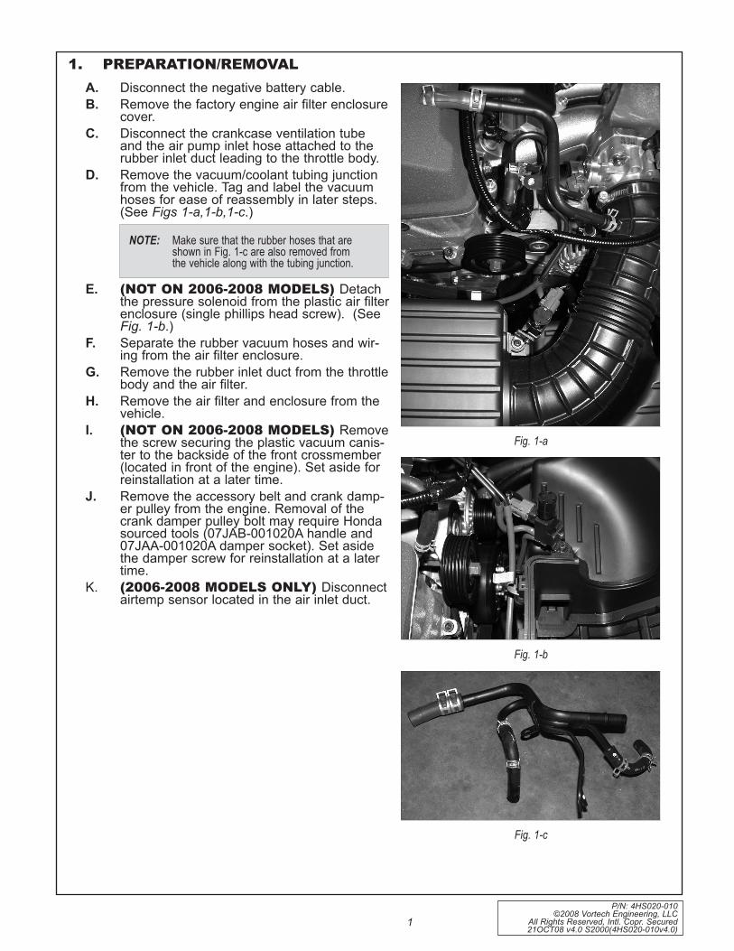
A. Disconnect the negative battery cable. B. Remove the factory engine air filter enclosure
cover.C. Disconnect the crankcase ventilation tube
and the air pump inlet hose attached to the rubber inlet duct leading to the throttle body.
D. Remove the vacuum/coolant tubing junction from the vehicle. Tag and label the vacuum hoses for ease of reassembly in later steps. (See Figs 1-a,1-b,1-c.)
E. (NOT ON 2006-2008 MODELS) Detach the pressure solenoid from the plastic air filter enclosure (single phillips head screw). (See Fig. 1-b.)
F. Separate the rubber vacuum hoses and wir-ing from the air filter enclosure.
G. Remove the rubber inlet duct from the throttle body and the air filter.
H. Remove the air filter and enclosure from the vehicle.
I. (NOT ON 2006-2008 MODELS) Remove the screw securing the plastic vacuum canis-ter to the backside of the front crossmember (located in front of the engine). Set aside for reinstallation at a later time.
J. Remove the accessory belt and crank damp-er pulley from the engine. Removal of the crank damper pulley bolt may require Honda sourced tools (07JAB-001020A handle and 07JAA-001020A damper socket). Set aside the damper screw for reinstallation at a later time.
K. (2006-2008 MODELS ONLY) Disconnect airtemp sensor located in the air inlet duct.
1. PREPARATION/REMOVAL
Fig. 1-a
Fig. 1-b
Fig. 1-c
NOTE: Make sure that the rubber hoses that are shown in Fig. 1-c are also removed from the vehicle along with the tubing junction.

P/N: 4HS020-010 ©2008 Vortech Engineering, LLC All Rights Reserved, Intl. Copr. Secured 21OCT08 v4.0 S2000(4HS020-010v4.0)
2
1. PREPARATION/REMOVAL, Cont.
Fig. 1-f
Fig. 1-g
Fig. 1-h
Fig. 1-d
reMoVe ScrewS
L. Remove the factory idler (smooth) pulley and hardware and set aside temporarily. (See Fig. 1-d)
M. Remove the two factory M8 x 1.25 screws that attach the front corner of the cylinder head to the engine front cove.r (See Fig. 1-f.)
N. Disconnect the wiring from the VTEC sole-noid assembly. Remove the three screws attaching the solenoid assembly to the side of the cylinder head. (See Figs. 1-g,1-h.) Set the VTEC solenoid assembly aside for mounting in a later step. Make sure that the o-ring seal-ing gasket does not get lost or damaged, because it will be re-used in a later step.
P/N: 4HS020-010 ©2008 Vortech Engineering, LLC
All Rights Reserved, Intl. Copr. Secured 21OCT08 v4.0 S2000(4HS020-010v4.0)
3
2. OIL FEED (2000-2005 MODELS ONLY)
Fig. 2-a
Fig. 2-b
Fig. 2-c
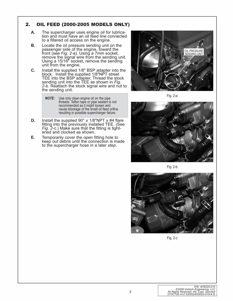
A. The supercharger uses engine oil for lubrica-tion and must have an oil feed line connected to a filtered oil access on the engine.
B. Locate the oil pressure sending unit on the passenger side of the engine, toward the front (see Fig. 2-a). Using a 7mm socket, remove the signal wire from the sending unit. Using a 15/16" socket, remove the sending unit from the engine.
C. Install the supplied 1/8" BSP adapter into the block. Install the supplied 1/8"NPT street TEE into the BSP adapter. Thread the stock sending unit into the TEE as shown in Fig. 2-b. Reattach the stock signal wire and nut to the sending unit.
D. Install the supplied 90° x 1/8"NPT x #4 flare fitting into the previously installed TEE. (See Fig. 2-c.) Make sure that the fitting is tight-ened and clocked as shown.
E. Temporarily cover the open fitting hole to keep out debris until the connection is made to the supercharger hose in a later step.
NOTE: Use only clean engine oil on the pipe threads. teflon tape or pipe sealant is not recommended as it might loosen and cause blockage of the small oil feed orifice resulting in possible supercharger failure.
oil preSSUre Sending Unit

P/N: 4HS020-010 ©2008 Vortech Engineering, LLC All Rights Reserved, Intl. Copr. Secured 21OCT08 v4.0 S2000(4HS020-010v4.0)
4
3. OIL DRAIN (2000-2005 MODELS ONLY)
Fig. 3-a
Fig. 3-b
A. Drain the engine oil and change the filter.B. To provide an oil drain for the supercharger, it
is necessary to make a hole in the pan. C. Remove (6 screws) the tubular chassis cross-
member located beneath the rear of the engine.
D. Remove the oil pan bumper that is attached to the vehicle frame in front of the oil pan.
E. Remove the two screws that attach the oil pan to the transmission bellhousing.
F. Remove the two lower A/C compressor pump mounting bolts that attach to the oil pan mounting bracket. Leave the small aluminum mounting bracket attached to the pan.
G. Remove the remaining oil pan screws around the perimeter of the pan and carefully remove the pan.
H. Locate and mark the drain hole location on the oil pan as per Figs. 3-a, 3-b. The hole location is between the two fins as shown, and down from the sealing surface of the pan 1.25". Grind down the fins on the oil pan as shown.
I. Using the supplied 9/16" rota-broach cutter and arbor, carefully machine a through hole into the pan in the location specified.
J. From the outside of the pan, tap the hole with a 3/8" NPT tap approximately 1/4" deep. Pack the flutes of the tap with heavy grease to hold the chips. Thoroughly clean the threads and hole with acetone or lacquer thinner.
K. Using a small amount of silicone sealer, install the 3/8"NPT x 1.5" hex nipple into the oil pan. Thread the supplied 3/8"NPT female x -8 flare fitting onto the hex nipple. Temporarily cap the fitting until the drain hose is connected in Step 12.
L. Thoroughly clean the mating surface of the oil pan flange and the bottom of the engine block. The surfaces must be free from oil so that a proper seal can be achieved when the pan is reinstalled.
M. Apply a small amount of Hondabond sealer (available at the local Honda dealership) to the oil pan mating flange.
N. Reattach the pan to the engine. Reinstall all of the factory hardware.
O. Reinstall the two A/C compressor screws, factory oil pan bumper and chassis cross-member.
P. Re-fill engine with factory specified weight oil. Vortech recommends the use of synthetic oil.
1.25"
grind FinS aS SHown

P/N: 4HS020-010 ©2008 Vortech Engineering, LLC
All Rights Reserved, Intl. Copr. Secured 21OCT08 v4.0 S2000(4HS020-010v4.0)
5
4. CRANk DAMPER PULLEY INSTALLATIONA. Locate the supplied damper pulley and billet
aluminum supercharger crank pulley.B. The aluminum supercharger crank pulley is to
be installed over the new damper pulley as shown in Fig. 4-a. Be sure to rotate the alu-minum pulley so that the holes properly line up with the corresponding threaded holes in the damper. Ensure that the damper is smooth and clean where the aluminum pulley is to be seated.
C. Carefully lower the aluminum pulley down onto the damper. Make sure that the alumi-num pulley is completely seated onto the damper. Do not hammer or pry the pulley into place. If necessary, the aluminum pulley may be lightly heated to allow for an easier fit onto the damper pulley
D. Secure the pulley and damper together using the six supplied 10-24 x .50 socket head screws. Use a drop of blue Loctite on the threads on each of the screws. Torque the screws to 50 in/lbs (4-5 ft/lbs.)
E. Clean the damper pulley screw and washer that were removed in Step 1. Using a small amount of engine oil, lubricate the screw threads and the bottom side of the screw head (area that mates to the washer). Install the new crank pulley assembly onto the engine. Torque the screw to 181 lb/ft. Do not use an impact wrench. In order to achieve the correct torque on the screw, Honda sourced tools may be required (07JAB-001020A handle and 07JAA-001020A damper socket) to keep the assembly from rotating.

P/N: 4HS020-010 ©2008 Vortech Engineering, LLC All Rights Reserved, Intl. Copr. Secured 21OCT08 v4.0 S2000(4HS020-010v4.0)
6
4. CRANk DAMPER PULLEY INSTALLATION, cont’d
VORTECH SUPPLIEDCRANK DAMPER
PULLEY 6.0" ALUMINUM
PULLEYSUPERCHARGER CRANK
6 x 10-24 x .50SCREWS (TORQUEEVENLY TO 50 IN/LBS)
Fig. 4-a
P/N: 4HS020-010 ©2008 Vortech Engineering, LLC
All Rights Reserved, Intl. Copr. Secured 21OCT08 v4.0 S2000(4HS020-010v4.0)
7
5. FUEL MANAGEMENT UNIT (2000-2005 MODELS ONLY)
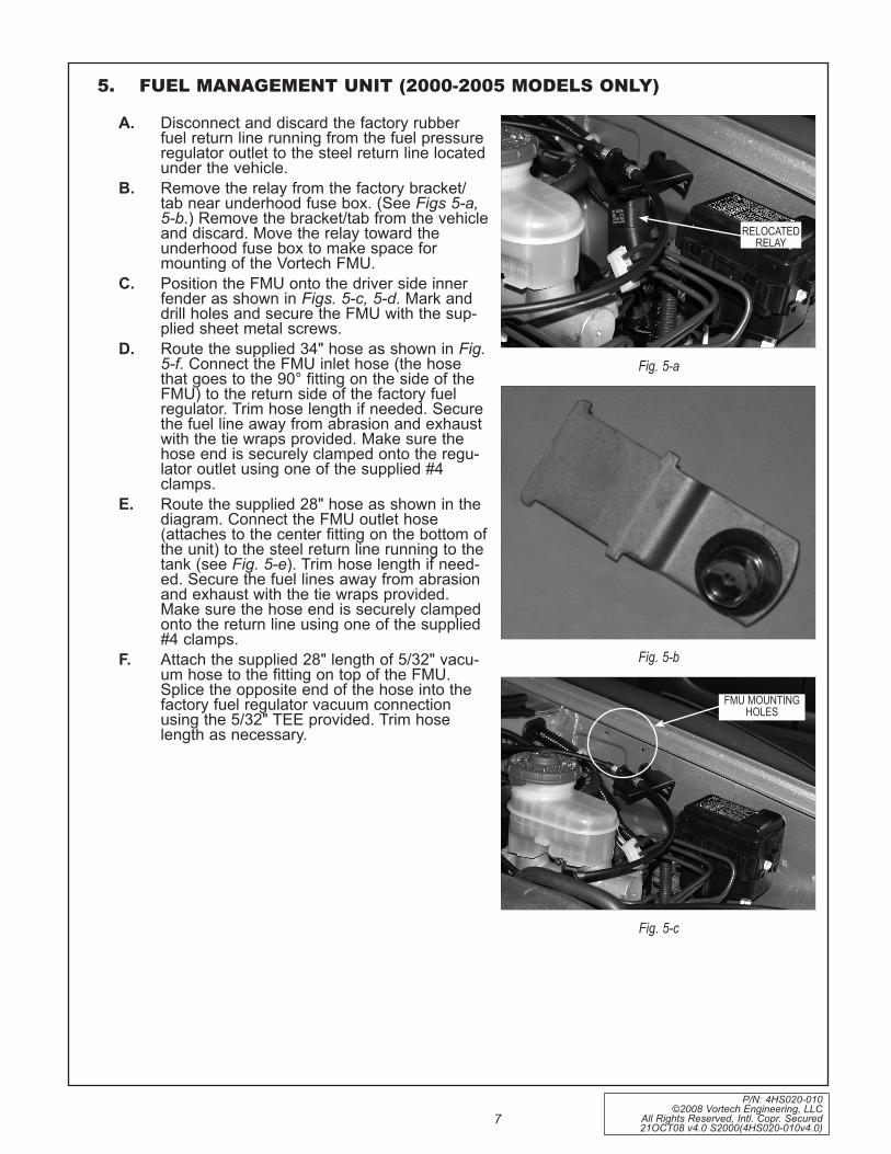
A. Disconnect and discard the factory rubber fuel return line running from the fuel pressure regulator outlet to the steel return line located under the vehicle.
B. Remove the relay from the factory bracket/tab near underhood fuse box. (See Figs 5-a, 5-b.) Remove the bracket/tab from the vehicle and discard. Move the relay toward the underhood fuse box to make space for mounting of the Vortech FMU.
C. Position the FMU onto the driver side inner fender as shown in Figs. 5-c, 5-d. Mark and drill holes and secure the FMU with the sup-plied sheet metal screws.
D. Route the supplied 34" hose as shown in Fig. 5-f. Connect the FMU inlet hose (the hose that goes to the 90° fitting on the side of the FMU) to the return side of the factory fuel regulator. Trim hose length if needed. Secure the fuel line away from abrasion and exhaust with the tie wraps provided. Make sure the hose end is securely clamped onto the regu-lator outlet using one of the supplied #4 clamps.
E. Route the supplied 28" hose as shown in the diagram. Connect the FMU outlet hose (attaches to the center fitting on the bottom of the unit) to the steel return line running to the tank (see Fig. 5-e). Trim hose length if need-ed. Secure the fuel lines away from abrasion and exhaust with the tie wraps provided. Make sure the hose end is securely clamped onto the return line using one of the supplied #4 clamps.
F. Attach the supplied 28" length of 5/32" vacu-um hose to the fitting on top of the FMU. Splice the opposite end of the hose into the factory fuel regulator vacuum connection using the 5/32" TEE provided. Trim hose length as necessary.
Fig. 5-c
Fig. 5-a
Fig. 5-b
FMU MoUnting HoleS
relocated relay

P/N: 4HS020-010 ©2008 Vortech Engineering, LLC All Rights Reserved, Intl. Copr. Secured 21OCT08 v4.0 S2000(4HS020-010v4.0)
8
5. FUEL MANAGEMENT UNIT, (2000-2005 MODELS ONLY) Cont’d.
Fig. 5-d
Fig. 5-e
Factory retUrnline into tank

P/N: 4HS020-010 ©2008 Vortech Engineering, LLC
All Rights Reserved, Intl. Copr. Secured 21OCT08 v4.0 S2000(4HS020-010v4.0)
9
5. FUEL MANAGEMENT UNIT, (2000-2005 MODELS ONLY) Cont’d.
ATTA
CH
TOM
ANIF
OLD
VAC
UU
M
FMU
/FU
ELLI
NE
DIA
GRA
M
FUEL
PRES
SURE
REG
ULA
TOR
SUPP
LIED
34"
FMU
SEC
URE
BOTH
END
SW
ITH
CLA
MPS
INLE
TH
OSE
–SU
PPLI
ED28
"FM
UO
UTL
ETH
OSE
–SE
CU
REBO
THEN
DS
WIT
HC
LAM
PS
FMU
OU
TLET
FMU
INLE
T
VEH
ICLE
'SST
OC
KRE
TURN
LIN
E(T
OTA
NK)
GRA
PHIC
SEVE
NFi
g. 5
-f
P/N: 4HS020-010 ©2008 Vortech Engineering, LLC All Rights Reserved, Intl. Copr. Secured 21OCT08 v4.0 S2000(4HS020-010v4.0)
10
6. FUEL PUMP REPLACEMENT (2000-2005 MODELS ONLY)
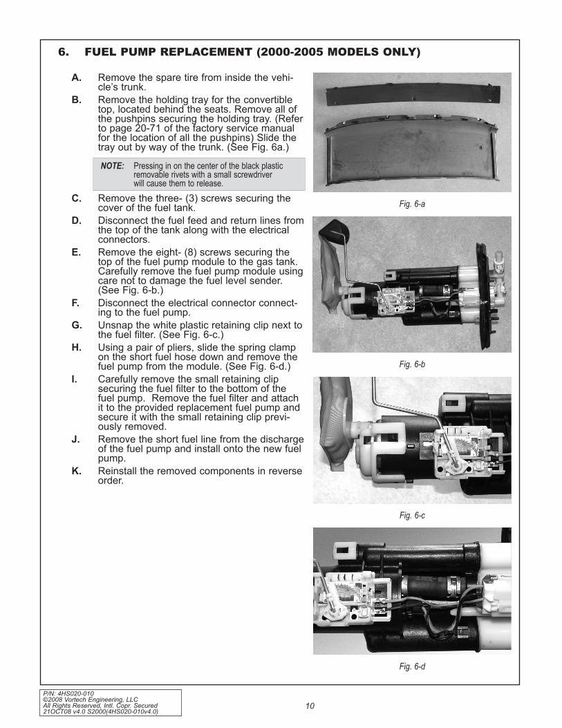
A. Remove the spare tire from inside the vehi-cle’s trunk.
B. Remove the holding tray for the convertible top, located behind the seats. Remove all of the pushpins securing the holding tray. (Refer to page 20-71 of the factory service manual for the location of all the pushpins) Slide the tray out by way of the trunk. (See Fig. 6a.)
C. Remove the three- (3) screws securing the cover of the fuel tank.
D. Disconnect the fuel feed and return lines from the top of the tank along with the electrical connectors.
E. Remove the eight- (8) screws securing the top of the fuel pump module to the gas tank. Carefully remove the fuel pump module using care not to damage the fuel level sender. (See Fig. 6-b.)
F. Disconnect the electrical connector connect-ing to the fuel pump.
G. Unsnap the white plastic retaining clip next to the fuel filter. (See Fig. 6-c.)
H. Using a pair of pliers, slide the spring clamp on the short fuel hose down and remove the fuel pump from the module. (See Fig. 6-d.)
I. Carefully remove the small retaining clip securing the fuel filter to the bottom of the fuel pump. Remove the fuel filter and attach it to the provided replacement fuel pump and secure it with the small retaining clip previ-ously removed.
J. Remove the short fuel line from the discharge of the fuel pump and install onto the new fuel pump.
K. Reinstall the removed components in reverse order.
Fig. 6-a
Fig. 6-b
Fig. 6-c
Fig. 6-d
NOTE: pressing in on the center of the black plastic removable rivets with a small screwdriver will cause them to release.

P/N: 4HS020-010 ©2008 Vortech Engineering, LLC
All Rights Reserved, Intl. Copr. Secured 21OCT08 v4.0 S2000(4HS020-010v4.0)
11
7. FUEL RAIL/REGULATOR MODIFICATIONS (2004/2005 Models Only)
A. Using a 10mm socket, remove the two nuts that secure the plastic cover on the fuel rail. Set the nuts and cover aside to be reinstalled later.
B. Disconnect the fuel feed line running to the middle of the factory fuel rail.
C. Remove the hose connected to the return side of the fuel regulator.
D. Loosen the factory screws securing the fuel rail and remove the fuel rail from the vehicle.
E. Using Figs. 7-a, 7-b, mark the location to be drilled. Keeping the drill perpendicular to the fuel rail, drill a .339" (R drill bit) hole into the top of the fuel rail.
F. With a 1/8"NPT tap, thread the newly drilled hole until the tap is 1/3 of the way inside the hole or the supplied 1/8"NPT x -4 fitting can be started. Thoroughly clean all debris from the fuel rail.
G. Using a thread sealant, install the 1/8"NPT end of the supplied fitting into the fuel rail until the fitting is snug.
H. Reinstall the fuel rail back into the vehicle. Reconnect the fuel feed line and secure all the factory hardware.
Fig. 7-b
FUEL PRESSUREREGULATOR
DRILL .078" HOLE
Fig. 7-c
NOTE: this step is also recommended for 2001-2003 model years.
NOTE: at this time, leave the fuel return line dis-connected from the fuel regulator.
2004/2005 FUEL RAILMODIFICATIONS
DRILL WITH AN ÔRÕ DRILLAND TAP 1/8 NPT
4.10"
.60"
I. Remove the two screws securing the fuel pressure regulator to the fuel rail.
J. Following Fig. 7-c, drill a .078" hole in the rear of the regulator. (This allows the regula-tor to bypass more fuel due to increased stat-ic fuel pressure.)
K. Clean all debris and reinstall the fuel pres-sure regulator back onto the fuel rail, verifying alignment of the O-ring.
L. Reconnect the fuel return line to the bottom barb on the fuel pressure regulator.
M. Re-install the plastic fuel rail cover using the factory nuts to secure it. The cover will need to be trimmed to clear the 1/8"NPT fitting pre-viously installed.
Fig. 7-a
FUel Feed line
SUpplied -4 x 1/8”npt Fitting
retUrn HoSe

P/N: 4HS020-010 ©2008 Vortech Engineering, LLC All Rights Reserved, Intl. Copr. Secured 21OCT08 v4.0 S2000(4HS020-010v4.0)
12
8. SUPERCHARGER MOUNTING BRACkET/PLATE INSTALLATION
A. Detach the factory wiring harness from the rear of the front crossmember for mounting bracket clearance. Push the harness down toward the steering rack.
B. Remove the two factory M6 x 1.0 screws from the passenger side front of the engine near the crank pulley at the location shown in Fig. 8-a.
C. Locate the lower supercharger plate spacer. This is a .75" thick aluminum spacer that is 2.9" wide x 4.05" tall with two 1/2" round protrusions machined into one end. Slide the two supplied 10 mm studs through the holes in the lower plate spacer. With the studs located loosely through the lower plate spacer, thread the two studs into the front cover as shown in Figs. 8-b, 8-n, 8-o. This step must be done as described because of the limited space available in the engine compartment. Use a drop of blue Loctite on the threads of the studs before threading them into the engine. Tighten the studs into the front of the engine by using a stud wrench, or by temporarily threading two nuts on the end of each stud and torquing. Remove the nuts from the ends of the studs.
D. Attach the supplied 6 grooved idler pulley to the main supercharger mounting plate as shown in Figs. 8-c, 8-d, 8-e, 8-f. Slide one of the supplied 3/8-24 x 3.5" screws through the machined bearing pilot, 6 groove idler pulley and steel idler spacer (1.772" effective length x Ø.406" through hole). Attach the complete assembly to the aluminum mounting plate by threading the 3/8-24 x 3.5" screw through the plate and into the threaded steel insert that is pressed into the plate.
E. Attach the belt tensioner adjustment screw, ten-sioner arbor and adjustment screw locator block to the supercharger mounting plate as shown in Figs. 8-e, 8-f, 8-g, 8-h, 8-i. Secure the assembly to the plate by threading the two 1/4-20 x .75" socket head screws through the plate and into the adjustment screw locator block as shown. Make sure the locator block is positioned as shown in Fig. 8-h or you will experience oil feed line clearance issues.
F. Slide the supplied smooth idler pulley and steel idler spacer (1.772" effective length x Ø.515" through hole) over the tensioner arbor that was previously installed onto the mounting plate. Install the 12 mm washer and 1/2-20 jam lock nut over the idler and arbor. Do not tighten the nut at this time. (See Fig. 8-f.)
G. (2000-2005 Models only) Remove the blue plastic dust cap located on the 1/2" oil drain fit-ting on the bottom of the supercharger. Attach the supplied 1/2" x 18" fabric braided oil drain hose to the supercharger drain fitting.
Fig. 8-a
Fig. 8-b
Fig. 8-c
Fig. 8-d
NOTE: Use a drop of blue loctite on all fastener threads prior to assembly.
P/N: 4HS020-010 ©2008 Vortech Engineering, LLC
All Rights Reserved, Intl. Copr. Secured 21OCT08 v4.0 S2000(4HS020-010v4.0)
13
8. SUPERCHARGER MOUNTING BRACkET/PLATE INSTALLATION, cont’d
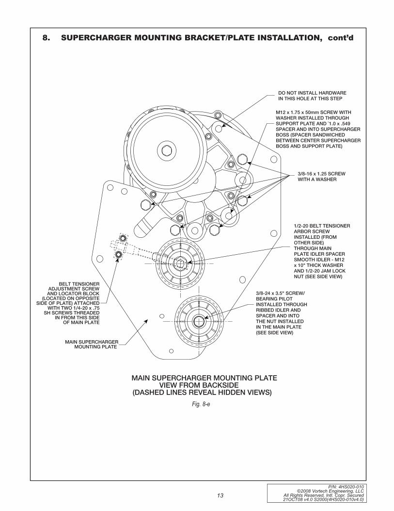
Fig. 8-e
DO NOT INSTALL HARDWAREIN THIS HOLE AT THIS STEP
M12 x 1.75 x 50mm SCREW WITHWASHER INSTALLED THROUGHSUPPORT PLATE AND ¯1.0 x .549SPACER AND INTO SUPERCHARGERBOSS (SPACER SANDWICHEDBETWEEN CENTER SUPERCHARGERBOSS AND SUPPORT PLATE)
3/8-16 x 1.25 SCREWWITH A WASHER
3/8-24 x 3.5" SCREW/BEARING PILOTINSTALLED THROUGHRIBBED IDLER ANDSPACER AND INTOTHE NUT INSTALLEDIN THE MAIN PLATE(SEE SIDE VIEW)
BELT TENSIONERADJUSTMENT SCREWAND LOCATOR BLOCK
(LOCATED ON OPPOSITESIDE OF PLATE) ATTACHED
WITH TWO 1/4-20 x .75SH SCREWS THREADED
IN FROM THIS SIDEOF MAIN PLATE
MAIN SUPERCHARGERMOUNTING PLATE
1/2-20 BELT TENSIONERARBOR SCREWINSTALLED (FROMOTHER SIDE)THROUGH MAINPLATE IDLER SPACERSMOOTH IDLER - M12x 10" THICK WASHERAND 1/2-20 JAM LOCKNUT (SEE SIDE VIEW)
GRAPHIC TWO
MAIN SUPERCHARGER MOUNTING PLATEVIEW FROM BACKSIDE
(DASHED LINES REVEAL HIDDEN VIEWS)
P/N: 4HS020-010 ©2008 Vortech Engineering, LLC All Rights Reserved, Intl. Copr. Secured 21OCT08 v4.0 S2000(4HS020-010v4.0)
14
8. SUPERCHARGER MOUNTING BRACkET/PLATE INSTALLATION, cont’d.
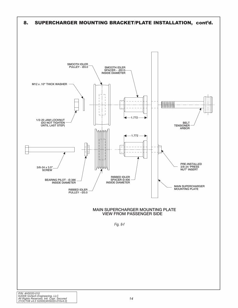
BELTTENSIONER
ARBOR
MAIN SUPERCHARGERMOUNTING PLATE
PRE-INSTALLED3/8-24 'PRESSNUT" INSERT
RIBBED IDLERSPACER .406Ø
INSIDE DIAMETER
GRAPHIC THREE
MAIN SUPERCHARGER MOUNTING PLATEVIEW FROM PASSENGER SIDE
RIBBED IDLERPULLEY - 3.0Ø
SMOOTH IDLERSPACER - . 515Ø
INSIDE DIAMETER
SMOOTH IDLERPULLEY - 3.0Ø
M12 x .10" THICK WASHER
1/2-20 JAM LOCKNUT(DO NOT TIGHTENUNTIL LAST STEP)
3/8-24 x 3.5"SCREW
BEARING PILOT - .386ØINSIDE DIAMETER
1.772
1.772
Fig. 8-f

P/N: 4HS020-010 ©2008 Vortech Engineering, LLC
All Rights Reserved, Intl. Copr. Secured 21OCT08 v4.0 S2000(4HS020-010v4.0)
15
8. SUPERCHARGER MOUNTING BRACkET/PLATE INSTALLATION, cont’d.
Fig. 8-g
Fig. 8-h
Fig. 8-i
belt tenSionerarbor Screw
belt tenSioneradjUStMent Screw
adjUStMent Screwlocator block

P/N: 4HS020-010 ©2008 Vortech Engineering, LLC All Rights Reserved, Intl. Copr. Secured 21OCT08 v4.0 S2000(4HS020-010v4.0)
16
Secure with a #8 hose clamp. Make sure that the hose clamp housing is clocked down toward the supercharger so that it will not cause interference with the supercharger mounting plate that is to be installed. (See Fig. 8-j.)
H. (2000-2005 Models Only) Remove the blue plastic dust cap located on the brass oil feed nozzle on the side of the supercharger. Thread the supplied steel 1/8" NPT x 45° x –4JIC fitting into the supercharger oil feed nozzle. Carefully tighten and clock the 45° fit-ting as shown in Figs. 8-j, 8-k. Use caution when tightening the oil feed fitting, as the brass nozzle may be broken if care is not exercised. Connect the supplied oil feed line to the flare fitting. Temporarily cover the open end from debris until the connection is made to the engine in step 15.
I. Attach the supercharger unit to the mounting plate as shown using the five supplied 3/8-16 x 1.25" screws with AN washers. The sixth supercharger mounting hole should remain empty at this time. (Refer back to Fig. 8-e, and Fig. 8-k.)
J. Using two of the supplied 3/8-16 x 1.25" screws with AN washers, attach the upper supercharger support plate to the super-charger mounting block as shown in Figs. 8-l, 8-m. Thread the screws down until the heads almost touch the plate/washers. Do not tight-en the screws at this time.
K. From the back side, slide the supplied 3/8-16 x 3.5" screw and AN washer through the top hole (refer to Figs. 8-n, 8-o) of the upper sup-port plate and into one of the supplied Ø.875 O.D. x 1.858" long spacers. Loosely mount the support plate assembly with spacer onto the supercharger and previously assembled main supercharger plate.
NOTE: Use only clean engine oil on the pipe threads. teflon tape or pipe sealant is not recommended as it might loosen and cause blockage of the small oil feed orifice resulting in possible supercharger failure.
NOTE: when directed, it is important to follow the suggestion: “do not tighten the screws”. Failure to follow this direction will result in bracket misalignment and the possibility of the Vtec solenoid not maintaining a prop-er seal. thread the applicable screws and nuts in until the head almost touches down (.01-.02" clearance). this will allow the bracket to properly align itself to the engine and other components in the assembly during installation.
8. SUPERCHARGER MOUNTING BRACkET/PLATE INSTALLATION, cont’d.
Fig. 8-j (2000-2005 only)
Fig. 8-k
Fig. 8-l
no FaStener Here at tHiS tiMe
3/8-16 x 1.25ScrewS witH an waSHerS
(do not tigHten)

P/N: 4HS020-010 ©2008 Vortech Engineering, LLC
All Rights Reserved, Intl. Copr. Secured 21OCT08 v4.0 S2000(4HS020-010v4.0)
17
8. SUPERCHARGER MOUNTING BRACkET/PLATE INSTALLATION, cont’d.
Fig. 8-m
SUPERCHARGER SUPPORT PLATEVIEW FROM FRONT (BEFORE
JOINING TO MAIN PLATEASSEMBLY)
PRE-INSTALLED 3/8-24 "PRESS NUT"INSERT (LOCATEDON BACKSIDE OFPLATE)
SUPERCHARGERSUPPORT PLATE
3/8-16 x 1.25 SCREWS WITHA WASHERS (DO NOTTIGHTEN SCREWS UNTILENTIRE BRACKETASSEMBY IS MOUNTEDONTO ENGINE)
HOLE FOR M12 x 1.75 x50mm SCREW (INSTALLED
FROM BACKSIDE)
SUPERCHARGER PLATEMOUNTING BLOCK(SANDWICHED BETWEENVTEC SOLENOID ANDCYLINDER HEAD)

P/N: 4HS020-010 ©2008 Vortech Engineering, LLC All Rights Reserved, Intl. Copr. Secured 21OCT08 v4.0 S2000(4HS020-010v4.0)
18
8. SUPERCHARGER MOUNTING BRACkET/PLATE INSTALLATION, cont’d.
Fig. 8-n
SUPERCHARGERPLATE MOUNTINGBLOCK (SANDWICHED BETWEEN
VTEC SOLENOID AND CYLINDER HEAD)
3/8-16 x 3/5" SCREW AND WASHER INSTALLEDFROM THE BACKSIDE THROUGH SUPPORT
PLA ACER AND INTOTE AND .875 x 1.858 SPØSUPERCHARGER(SPACER SANDWICHED
BETWEEN MAIN PLATE AND SUPPORT PLATE)
M12 x 1.75 x 50mm SCREW WITHW ALLED FROM THEASHER INST
BACKSIDE - THROUGH SUPPORTPLATE AND 1.0 x .549 SPACERØ
AND INTO SUPERCHARGER(SPACER SANDWICHED BETWEEN
CENTER SUPERCHARGERBOSSAND SUPPORT PLATE)
Ø3.0" SUPERCHARGERTENSIONER PULLEY
(SMOOTH)
BELT TENSIONER ARBOR
3/8-24 x 3.5" SCREWS/ANWASHERS INSTALLED
FROM THE FRONT -THROUGH MAIN PLATE
AND .875 x 1.858ØSPACERS AND INTO
SUPPORT PLATE (SPACERSSANDWICHED BETWEEN
MAIN PLATE AND SUPPORTPLATE)
BELT TENSIONER ADJUSTMENT SCREW
ADJUSTMENT SCREW AND LOCATORBLOCK ATTACHED WITH TWO 1/4-20 x .75
SH SCREWS THREADED IN FROM THEBACK SIDE OF MAIN PLATE
3/8-24 x 3.5 SCREW/BEARING PILOT INSTALLEDFROM THE BACKSIDE THROUGH RIBBED
IDLER AND SPACER AND INTO "PRESSED NUT"INSERT INSTALLED IN MAIN PLATE
M6 x 1.0 NUTS WITH WASHERS INSTALLEDONTO STUDS PREVIOUSLYTHREADED INTO
FRONT OF ENGINE (REMOVE FACTORYHARDWARE)
LOWER SUPERCHARGERPLATE SPACER (ROUNDPROTRUSIONS TO BE INSTALLED AGAINST THE
FRONT COVER)
SUPERCHARGERDRIVE BELT
FRONT VIEW OF ENGINE(DASHED LINES REVEAL HIDDEN VIEWS)
5/16-18 x 1.0 SCREWSWITH AN WASHERSTHROUGH MAIN PLATEINTO LATERAL SUPPORTPLATE
FACTORYSPRING
TENSIONER
M10 x 1.25 x 115 SCREWWITH WASHER THROUGHMAIN PLATE - 1.0 xØØ2.726 SPACER, FACTORYIDLER AND INTO FACTORYTHREADED IDLERMOUNTING HOLEON FRONT COVER
FACTORY FIXEDIDLER
FACTORYBELT
FACTORYBOSSES
LOCATED ONENGINE FRONT
COVER
OIL PAN FLANGE
GRAPHIC FIVE
CRANKPULLEY

P/N: 4HS020-010 ©2008 Vortech Engineering, LLC
All Rights Reserved, Intl. Copr. Secured 21OCT08 v4.0 S2000(4HS020-010v4.0)
19
3/8-16 x 3.5" SCREW / A WASHERINSTALLED FROM THE BACKSIDETHROUGH SUPPOR TE ANDT PLAØ.875 x 1.858 SPACER AND INTO
UPPER SUPERCHARGERMOUNTINGBOSS (SPACER SANDWICHED BETWEEN
MAIN PLATE AND SUPPORT PLATE)
M6 1.0 x 80mm SCREWSTHROUGH VTEC SOLENOID
(NOT SHOWN), SUPERCHARGERPLATE MOUNTING BLOCK
AND INTO CYLINDER HEAD)
CYLINDER HEAD
M10 x 1.25 x 50mm SCREWWITH WASHER THROUGH
SUPERCHARGERPLATE MOUNTINGBLOCK AND INTO CYLINDER HEAD
SUPERCHARGERPLATEMOUNTING BLOCK
M12 x 1.75 x 50 SCREW
FACTORY FIXED IDLER
PRE-INSTALLED 3/8-24"PRESS NUT" INSERT (3 PLACES)
M12 WASHER
Ø1.0" x .549 SPACER
SUPERCHARGERSUPPORT PLATE
FRONT FACE OFENGINE BLOCK
SUPERCHARGERBRACKET ASSEMBLY VIEW FROM PASSENGER SIDE –VORTECHIDLERS AND SOME FASTENERSNOT SHOWN FOR CLARITY
(DASHED LINES REVEAL HIDDEN VIEWS)
LOWER SUPERCHARGERPLATE SPACER(ROUND PROTRUSIONS TO BE INSTALLEDAGAINST THE FRONT COVER)
SUPERCHARGERMOUNTING PLATE
M10 X 1.25 X 115 SCREWTHROUGH MAIN PLATEØ1.0 x 2.726 SPACERFACTORY IDLER ANDINTO FACTORYTHREADED IDLERMOUNTING HOLEON FRONT COVER
3/8-24 x 3.5" SCREWSINSTALLED FROM THEFRONT THROUGH MAINPLATE AND .875 x 1.858ØSPACERS AND INTOSUPPORT PLATE, SPACERSSANDWICHED BETWEENMAIN PLATE AND SUPPORTPLATE – 3 PLACES)
CENTER M12SUPERCHARGERBOSS
3/8"WASHER
Ø1.0" x 2.726STEEL SPACER
M10WASHER
M6 x 1.0 NUTS WITH WASHERS INSTALLEDONTO STUDS PREVIOUSLYTHREADEDINTO FRONT OF ENGINE
1.858
2.726
.549
8. SUPERCHARGER MOUNTING BRACkET/PLATE INSTALLATION, cont’d.
Fig. 8-o
P/N: 4HS020-010 ©2008 Vortech Engineering, LLC All Rights Reserved, Intl. Copr. Secured 21OCT08 v4.0 S2000(4HS020-010v4.0)
20
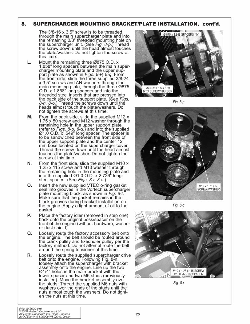
The 3/8-16 x 3.5" screw is to be threaded through the main supercharger plate and into the remaining 3/8" threaded mounting hole on the supercharger unit. (See Fig. 8-p.) Thread the screw down until the head almost touches the plate/washer. Do not tighten the screw at this time.
L. Mount the remaining three Ø875 O.D. x 1.858" long spacers between the main super-charger mounting plate and the upper sup-port plate as shown in Figs. 8-P, 8-q. From the front side, slide the three supplied 3/8-24 x 3.5" screws and AN washers through the main mounting plate, through the three Ø875 O.D. x 1.858" long spacers and into the threaded steel inserts that are pressed into the back side of the support plate. (See Figs. 8-n, 8-o.) Thread the screws down until the heads almost touch the plate/washers. Do not tighten the screws at this time.
M. From the back side, slide the supplied M12 x 1.75 x 50 screw and M12 washer through the remaining hole in the upper support plate (refer to Figs. 8-o, 8-q.) and into the supplied Ø1.0 O.D. x .549" long spacer. The spacer is to be sandwiched between the front side of the upper support plate and the center 12 mm boss located on the supercharger cover. Thread the screw down until the head almost touches the plate/washer. Do not tighten the screw at this time.
N. From the front side, slide the supplied M10 x 1.25 x 115 screw and M10 washer through the remaining hole in the mounting plate and into the supplied Ø1.0 O.D. x 2.726" long steel spacer. (See Figs. 8-r, 8-s.)
O. Insert the new supplied VTEC o-ring gasket seal into grooves in the Vortech supercharger plate mounting block. as shown in Fig. 8-t. Make sure that the gasket remains in the block grooves during bracket installation on the engine. Apply a light amount of oil to the gasket.
P. Place the factory idler (removed in step one) back onto the original boss/spacer on the front of the engine (without hardware, washer or dust shield).
Q. Loosely route the factory accessory belt onto the engine. The belt should be routed around the crank pulley and fixed idler pulley per the factory method. Do not attempt route the belt around the spring tensioner at this time.
R. Loosely route the supplied supercharger drive belt onto the engine. Following Fig. 8-n, loosely attach the supercharger with bracket assembly onto the engine. Line up the two Ø1/4" holes in the main bracket with the lower spacer and two M6 studs (previously installed). Move the bracket assembly over the studs. Thread the supplied M6 nuts with washers over the ends of the studs until the nuts almost touch the washers. Do not tight-en the nuts at this time.
8. SUPERCHARGER MOUNTING BRACkET/PLATE INSTALLATION, cont’d.
Fig. 8-p
Fig. 8-q
Fig. 8-r
3/8-16 x 3.5 Screwinto SUpercHarger
Ø.875 x 1.858 SpacerS (4x)
M12 x 1.75 x 50Screw/waSHer
M10 x 1.25 x 115 ScrewwitH Ø2.726” Spacer

P/N: 4HS020-010 ©2008 Vortech Engineering, LLC
All Rights Reserved, Intl. Copr. Secured 21OCT08 v4.0 S2000(4HS020-010v4.0)
21
8. SUPERCHARGER MOUNTING BRACkET/PLATE INSTALLATION, cont’d.
Fig. 8-s
Fig. 8-t
Slide tHe Ø1.0” x 2.726”Spacer onto tHe M10
x 1.25 x 115 ScrewbeFore attacHing
tHe MoUnting plateto tHe engine

P/N: 4HS020-010 ©2008 Vortech Engineering, LLC All Rights Reserved, Intl. Copr. Secured 21OCT08 v4.0 S2000(4HS020-010v4.0)
22
S. Align the M10 x 1.25" x 115 screw (previously inserted through the front of the main super-charger plate) into the factory idler pulley mount on the front cover. (See Fig. 8-u.) Make sure that the supplied Ø1.0" O.D. x 2.726" long spacer is sandwiched between the back of the supercharger mounting plate and the inner bearing race of the factory idler. Do not tighten any screws at this time.
T. Insert the three supplied M6 x 1.0" x 80 screws with washers through the previously removed VTEC solenoid, the Vortech super-charger plate mounting block and into the side of the cylinder head. (See Figs. 8-v, 8-w.) Make sure that both of the VTEC gas-kets remain in their proper locations during bracket installation on the engine. Thread the supplied M10 x 1.25 x 50 screw with washer into the remaining hole in the supercharger plate mounting block and into the cylinder head. Thread the four screws down until the heads almost touch the washers. Do not tighten the screws at this time.
U. Attach the supplied lateral supercharger mounting plate (‘L’ shaped bracket) support to the front corner of the cylinder head as shown using the supplied M8 x 1.25 x 45 socket head screws (no washers are used here). (See Figs. 8-u, 8-x). Thread the screws down until the heads almost touch the plate. Do not tighten the screws.
V. Align the two threaded holes in the end of the lateral support with the two holes in the supercharger mounting plate. Slide the two supplied 5/16-18 x 1.0" screws with AN wash-ers through the remaining two holes in the supercharger mounting plate and into the lat-eral support. Thread the screws down until the heads almost touch the washers. Do not tighten the screws at this time.
W. Secure the completed mounting bracket assembly to the engine by lightly “snugging” the hardware in the following sequence: 1. Four VTEC solenoid mounting screws.2. 3/8-16 x 3.5" screw running through the
top hole of the upper support plate, Ø.875" O.D. x 1.858" long spacer and into the supercharger.
3. M12 x 1.75" x 50 screw running through the upper support plate, Ø1.0 O.D. x .549"
NOTE: when installing the supercharger with bracket assembly onto the engine, the belt must be manipulated so that it is properly routed around the idler, tensioner, super-charger pulley and lower supercharger plate spacer. (refer back to Fig. 8-n.)
8. SUPERCHARGER MOUNTING BRACkET/PLATE INSTALLATION, cont’d.
Fig. 8-u
Fig. 8-v
Fig. 8-w
lateral MoUnting plate
M10 x 1.25" x 50

P/N: 4HS020-010 ©2008 Vortech Engineering, LLC
All Rights Reserved, Intl. Copr. Secured 21OCT08 v4.0 S2000(4HS020-010v4.0)
23
8. SUPERCHARGER MOUNTING BRACkET/PLATE INSTALLATION, cont’d.
Fig. 8-x
spacer and into the center 12 mm boss located on the supercharger cover.
4. Two 3/8-16 x 1.25" screws with AN wash-ers that attach the supercharger support plate to the supercharger mounting block.
5. M10 x 1.25 x 115 screw through the front of the supercharger mounting plate and into the factory idler pulley mount on the front cover.
6. Two 5/16-18 x 1.0" screws through the supercharger mounting plate and into the lateral support.
7. Two M8 x 1.25 x 45 socket head screws through the lateral support mounting plate, front corner of the cylinder head and into the front cover.
8. Three 3/8-24 x 3.5" screws running through the main mounting plate, Ø.875 O.D. x 1.858" long spacers and into the threaded steel inserts that are pressed into the back side of the support plate.
9. Two M6 nuts that are threaded onto the two studs inserted into the front of the engine.
X. Repeat the sequence above with final torqu-ing of all hardware.
Y. Reconnect the previously removed VTEC wir-ing connections.
Z. (NOT ON 2006-2008 Models) Reattach the plastic vacuum canister to the backside of the front crossmember (located in front of the engine) using the factory screw that was removed in step 1. Make sure that there is enough clearance between the vacuum hose and the crank pulley.
AA. (2006-2008 Models only) Secure the stainless steel oil service line away from hot or morning assemblies that may damage it. Locate the line so that it maybe easily accessed for service.
two 5/16-18 x 1"ScrewS witHan waSHerS
two M8 x 1.25 x 45Socket Head ScrewS
(no waSHerS)

P/N: 4HS020-010 ©2008 Vortech Engineering, LLC All Rights Reserved, Intl. Copr. Secured 21OCT08 v4.0 S2000(4HS020-010v4.0)
24
A. Disconnect the fuel feed line where it con-nects to the fuel rail. See Fig 9-a
B. Disconnect the four fuel injector harness connections from the injectors. Remove the four retaining screws that secure the fuel rail to the intake manifold. Gently pull up on the fuel rail and remove the fuel rail and injectors from the engine and set this assembly on a clean work surface.
C. Remove the injector retaining clips and set aside. Remove the factory fuel injectors and discard.
D. Remove the factory studded standoffs that secured the upper mounts of the fuel rail.
E. Locate the supplied fuel injectors. Lubricate the injector O-rings with clean motor oil and install in the fuel rail. Reinstall the factory injector retaining clips.
F. Drilling the upper holes on the fuel rail mounting points may be required to allow for the M8 bolts to pass through.
G. Lower the fuel rail/injector assembler onto the intake manifold, making sure the injec-tors seat properly in the injector ports. Position the supplied 1.59” and .50” spac-ers under the mounting tabs and secure the fuel rail using the M6 x 30mm and M8 x 55mm hardware provided. See Fig 9-b
H. Reconnect the four factory fuel injector’s connectors using the supplied injector har-ness adapters. Reconnect the factory fuel feed line from the fuel tank. See Fig 9-c
9. FUEL INjECTOR REPLACEMENT (2006-2008 MODELS ONLY)
Fig. 9-a
Fig. 9-b
Fig. 9-c
WARNING: The following step should be completed in a well ventilated area free of any possi-ble ignition source. Also have a fire extin-guisher standing by.
CAUTION: Fuel may be under high pressure. Loosen the fuel fill cap to help alleviate any resid-ual pressure in the fuel tank. Use care when disconnecting the fuel supply line.
NOTE: Use care not to get metal shavings in the fuel rail or injectors..

P/N: 4HS020-010 ©2008 Vortech Engineering, LLC
All Rights Reserved, Intl. Copr. Secured 21OCT08 v4.0 S2000(4HS020-010v4.0)
25
A. Locate the supplied charge cooler. Insert the supplied 60 lb/hr fuel injector into the injector base welded to the cooler discharge tube so that the injector plug is facing away from the injector base. (See Fig. 10-a.)
B. Insert the upper block over the injector. Secure the upper injector block with the sup-plied shoulder bolts.
C. Install the 1/8"NPT end of the supplied 90° fit-ting into the upper injector block. Orient the fitting so that it is pointing toward the back of the car.
D. Connect the 90° end of the supplied steel braided line to the -4 end on the installed straight fitting in the fuel rail. Run the fuel line toward the front of the car. Leave the open end of the fuel line disconnected until the charge cooler has been installed. (See Fig. 10-b.)
NOTE: lightly oil the o-rings on the injector for easier installation.
NOTE: thread sealant is recommenced on all fit-ting ends that have pipe threads.
10. SUPPLEMENTARY FUEL INjECTOR INSTALLATION (2004, 2005 MODELS ONLY)
Fig. 10-b
Fig. 10-a
P/N: 4HS020-010 ©2008 Vortech Engineering, LLC All Rights Reserved, Intl. Copr. Secured 21OCT08 v4.0 S2000(4HS020-010v4.0)
26
11. SUPERCHARGER BELT TENSIONER ADjUSTMENT
12. AIR PUMP INLET HOSE MODIFICATION (2000-2005 MODELS ONLY)
Fig. 12-b
Fig. 12-a
A. Make sure that the 1/2-20 jam lock nut previ-ously threaded onto the tensioner arbor is threaded down almost all of the way, but not tight. The belt is tightened/loosened by rotat-ing the belt tensioner adjustment screw. Tighten the belt until light resistance is felt in the belt tensioner adjustment screw. Proper belt tension is achieved when the belt can be twisted approximately 1/4 of a turn by hand. Adjust belt tension as needed. Do not over tension the belt.
B. From beneath the vehicle, tighten the 1/2-20 jam lock nut on the belt tensioner arbor.
C. Reinstall the factory accessory belt using the factory routing.
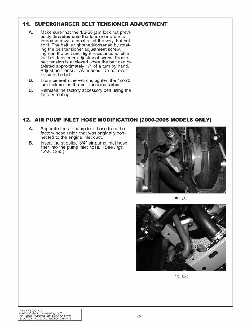
A. Separate the air pump inlet hose from the factory hose union that was originally con-nected to the engine inlet duct.
B. Insert the supplied 3/4" air pump inlet hose filter into the pump inlet hose. (See Figs. 12-a, 12-b.)

P/N: 4HS020-010 ©2008 Vortech Engineering, LLC
All Rights Reserved, Intl. Copr. Secured 21OCT08 v4.0 S2000(4HS020-010v4.0)
27
13. CHARGE AIR COOLER INSTALLATIONA. Attach the supplied breather/filter to the outlet
of the Vortech race bypass valve. Attach the Vortech race bypass valve to the charge cooler core using the supplied 1/4-20 x .50" socket head bolts and gasket. (See Fig. 13-a.)
B. Install two 1/2"NPT x 3/4" barb 90° fittings in the charge cooler water ports. (See Figs. 13-d, 10-a.)
C. Install the charge cooler between the super-charger and the throttle body using the sup-plied 2.75" sleeves and #44 hose clamps. The 3" long sleeve is to be placed on the throttle body.
D. Remove all of the plastic valance or splash panels located under the vehicle toward the front.
E. Install the two 1/4-20 nut plates into the bot-tom of the frame rails that extended forward from the radiator.
F. Install the two mounting brackets to the water cooler using 1/4-20 x 0.5" screws and wash-ers so that the inlet and outlet connections are facing the driver side of the vehicle. Be sure the port closest to the edge of the end tank is located on the top to allow for proper air purging.
G. Raise assembled cooler and brackets up into the cavity behind the front of the lower front grill and in front of the radiator. Line up the top of the mounting brackets with the previ-ously installed nut plates and secure with 1/4-20 X 1.0 screws and washers.
H. Adjust the cooler as needed and tighten all hardware on brackets.
I. Cut and route a length of the supplied 3/4" hose from the upper port on the water cooler, up behind the driver side headlight and across into the engine compartment to the lower driver side fitting on the charge cooler core. Secure each connection with nylon clamps provided.
J. Cut the electrical connector off of the end of water pump wiring harness and install one 14–16 Ga. ring terminal onto the brown (neg-ative) wire and the 18 Ga. insulated male slide connector onto the blue/green wire (positive).
K. Mount the water pump to the front of the pas-senger side core support using the supplied 1-11/16" Adel clamp and one #10 self-tapping screw. Test fit hoses from water pump cooler for proper positioning. Attach the ground wire (brown wire with ring terminal installed) from the water pump to the clamp. Angle the dis-charge of the water pump up as shown. (See Fig.13-f.)
The discharge of the water pump must be angled up. This is REQUIRED for the pump to purge itself of air.
Fig. 13-a
Fig. 13-b

P/N: 4HS020-010 ©2008 Vortech Engineering, LLC All Rights Reserved, Intl. Copr. Secured 21OCT08 v4.0 S2000(4HS020-010v4.0)
28
(FR
ON
T V
IEW
)
WAT
ER
C
OO
LER
CH
AR
GE
AIR
C
OO
LER
WAT
ER
FLO
W
WAT
ER
TA
NK
M
OU
NTI
NG
BR
AC
KE
T
WAT
ER
RE
SE
RV
OIR
WAT
ER
PU
MP
13. CHARGE AIR COOLER INSTALLATION, cont’d.
Fig.
13-
d

P/N: 4HS020-010 ©2008 Vortech Engineering, LLC
All Rights Reserved, Intl. Copr. Secured 21OCT08 v4.0 S2000(4HS020-010v4.0)
29
13. CHARGE AIR COOLER INSTALLATION, cont’d.L. Attach an 16 Ga. insulated female slide con-
nector to the yellow wire attached to the sup-plied relay. Route the yellow wire from the relay to the power distribution box located in front of thebattery. Following Fig. 13-g, route the wire up along the factory wires.
M. Remove the factory heater motor relay locat-ed in the underhood fusebox and modify to accept the electrical power tap as shown in Fig. 13-h. Reinstall the relay with the power tap. Connect the yellow wire to the power tap.
N. Attach the black wire from the supplied relay to a suitable ground.
O. Route the red wire from terminal #87 on the supplied relay down to the water pump. Install a female insulated slide connector onto the wire and connect to the blue/green (posi-tive) wire on the water pump.
P. Cut the supplied fuse holder wire and install the 12 GA ring terminal on one end and the 12 GA. solderless connector onto the other. Connect the #30 wire on the supplied relay to the solderless connector attached to the fuse holder. Connect the ring terminal to the posi-tive side of the battery and install the provid-ed fuse.
Q. Using one of the 4 X 12 3/4" 90° molded hoses attach the short leg to the discharge of the water pump and insert a 3/4" hose union into the long leg. Locate the 3/4" 150° molded hose and attach the long leg to the other end of the 3/4" hose union and route and attach the other end of the 150° molded hose to the lower port on the front mounted water cooler. Secure each connection with nylon clamps provided.
R. Temporarily install the water tank mounting bracket onto the water reservoir using the 1/4" hardware (see Fig. 13-k). Mock the water reservoir up as shown and mark the location on the vehicles frame (passenger side, outer frame rail) where the #10 self-tapping screws are to be located. Remove the 1/4" hardware attaching the bracket to the reservoir. Secure the bracket to the vehicle using the self-tap-ping screws. (See Fig. 13-j.)
S. Install the two remaining 90° brass fittings into the water reservoir using a small amount of thread sealant. Attach one end of the remaining Ø 3/4" hose to the top of the water reservoir and secure with a clamp.
T. Permanently attach the water reservoir to the mounting bracket using the 1/4" hardware.
U. Route the upper reservoir hose into the engine compartment (Fig. 13-k) under the radiator fan and then up between the radiator fan and the condenser fan finally connecting it to the passenger side fitting on the charge air cooler. Secure the hose with one of the provided clamps.
Fig. 13-f
Fig. 13-g
Fig. 13-h
water pUMp oUtlet HoSe
ModiFy Here

P/N: 4HS020-010 ©2008 Vortech Engineering, LLC All Rights Reserved, Intl. Copr. Secured 21OCT08 v4.0 S2000(4HS020-010v4.0)
30
13. CHARGE AIR COOLER INSTALLATION, cont’d.
V. Measure between the bottom of the reservoir water outlet and the pump inlet and cut an appropriate section of hose and attach.
W. Trim valance as shown for clearance. X. Reinstall the lower front valance.Y. Temporarily plug the 90° fitting attached to
the driver side of the charge air cooler that connects to the water cooler outlet hose. Leave the hose that comes from the top fit-ting of the water cooler open to atmosphere.
Z. Fill the system at the charge air cooler with 1/4 - 1/3 of a gallon of anti-freeze. Slowly fill the remainder with water until it comes out of the open hose coming from the top of the water cooler, this will help to purge the sys-tem of air. Connect the hose coming from the top fitting on the water cooler to the open fit-ting on the charge air cooler and secure with the provided clamp. Continue to fill the sys-tem with water until it is full and install the cap onto the charge air cooler.
AA. With the battery reconnected, key the vehicle to the ON position. Slowly remove the cap on the charge air cooler and check the level of the coolant and make sure the coolant is flowing through the system. Run the system for a few minutes to allow any air trapped in the lower part of the system to escape. Top the system off with coolant if necessary and reinstall the cap. Fig. 13-j
Fig. 13-k
Fig. 13-l
triM aS reQUired
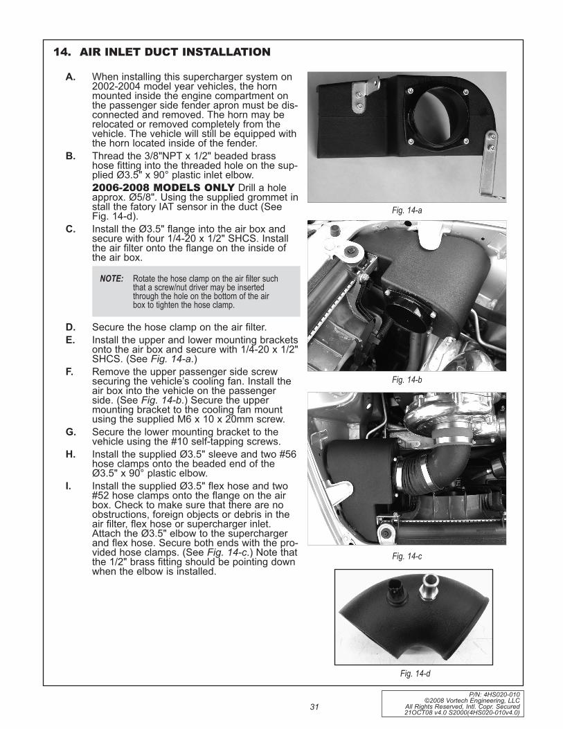
P/N: 4HS020-010 ©2008 Vortech Engineering, LLC
All Rights Reserved, Intl. Copr. Secured 21OCT08 v4.0 S2000(4HS020-010v4.0)
31
14. AIR INLET DUCT INSTALLATION
A. When installing this supercharger system on 2002-2004 model year vehicles, the horn mounted inside the engine compartment on the passenger side fender apron must be dis-connected and removed. The horn may be relocated or removed completely from the vehicle. The vehicle will still be equipped with the horn located inside of the fender.
B. Thread the 3/8"NPT x 1/2" beaded brass hose fitting into the threaded hole on the sup-plied Ø3.5" x 90° plastic inlet elbow.
2006-2008 MODELS ONLY Drill a hole approx. Ø5/8". Using the supplied grommet in stall the fatory IAT sensor in the duct (See Fig. 14-d).
C. Install the Ø3.5" flange into the air box and secure with four 1/4-20 x 1/2" SHCS. Install the air filter onto the flange on the inside of the air box.
D. Secure the hose clamp on the air filter.E. Install the upper and lower mounting brackets
onto the air box and secure with 1/4-20 x 1/2" SHCS. (See Fig. 14-a.)
F. Remove the upper passenger side screw securing the vehicle’s cooling fan. Install the air box into the vehicle on the passenger side. (See Fig. 14-b.) Secure the upper mounting bracket to the cooling fan mount using the supplied M6 x 10 x 20mm screw.
G. Secure the lower mounting bracket to the vehicle using the #10 self-tapping screws.
H. Install the supplied Ø3.5" sleeve and two #56 hose clamps onto the beaded end of the Ø3.5" x 90° plastic elbow.
I. Install the supplied Ø3.5" flex hose and two #52 hose clamps onto the flange on the air box. Check to make sure that there are no obstructions, foreign objects or debris in the air filter, flex hose or supercharger inlet. Attach the Ø3.5" elbow to the supercharger and flex hose. Secure both ends with the pro-vided hose clamps. (See Fig. 14-c.) Note that the 1/2" brass fitting should be pointing down when the elbow is installed.
NOTE: rotate the hose clamp on the air filter such that a screw/nut driver may be inserted through the hole on the bottom of the air box to tighten the hose clamp.
Fig. 14-a
Fig. 14-b
Fig. 14-c
Fig. 14-d
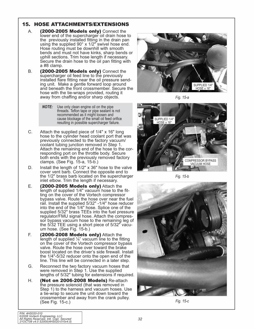
P/N: 4HS020-010 ©2008 Vortech Engineering, LLC All Rights Reserved, Intl. Copr. Secured 21OCT08 v4.0 S2000(4HS020-010v4.0)
32
15. HOSE ATTACHMENTS/EXTENSIONSA. (2000-2005 Models only) Connect the
lower end of the supercharger oil drain hose to the previously installed fitting in the drain pan using the supplied 90° x 1/2" swivel hose end. Hose routing must be downhill with smooth bends and must not have kinks, sharp bends or uphill sections. Trim hose length if necessary. Secure the drain hose to the oil pan fitting with a #8 clamp.
B. (2000-2005 Models only) Connect the supercharger oil feed line to the previously installed flare fitting near the oil pressure send-ing unit. Make a gentle forward loop around and beneath the front crossmember. Secure the hose with the tie-wraps provided, routing it away from chaffing and/or sharp objects.
C. Attach the supplied piece of 1/4" x 16" long hose to the cylinder head coolant port that was previously connected to the factory vacuum/coolant tubing junction removed in Step 1. Attach the remaining end of the hose to the cor-responding port on the throttle body. Secure both ends with the previously removed factory clamps. (See Fig. 15-a, 15-b.)
D. Install the length of 1/2" x 36" hose to the valve cover vent barb. Connect the opposite end to the 1/2" brass barb located on the supercharger inlet elbow. Trim the length if necessary.
E. (2000-2005 Models only) Attach the length of supplied 1/4" vacuum hose to the fit-ting on the cover of the Vortech compressor bypass valve. Route the hose over near the fuel rail. Install the supplied 5/32" -1/4" hose reducer into the end of the 1/4" hose. Splice one of the supplied 5/32" brass TEEs into the fuel pressure regulator/FMU signal hose. Attach the compres-sor bypass vacuum hose to the remaining leg of the 5/32 TEE using a short piece of 5/32" vacu-um hose. (See Fig. 15-b.)
F. (2006-2008 Models only) Attach the length of supplied ¼” vacuum line to the fitting on the cover of the Vortech compressor bypass valve. Route the hose over toward the brake boost located on the driver’s side firewall. Install the 1/4"-5/32 reducer onto the open end of the line. This line will be connected in a later step.
G. Reconnect the two factory vacuum hoses that were removed in Step 1. Use the supplied lengths of 5/32" tubing for extensions if required.
H. (Not on 2006-2008 Models) Re-attach the pressure solenoid (that was removed in Step 1) to the harness and vacuum hoses. Use a tie-wrap to secure the unit down toward the crossmember and away from the crank pulley. (See Fig. 15-c.)
NOTE: Use only clean engine oil on the pipe threads. teflon tape or pipe sealant is not recommended as it might loosen and cause blockage of the small oil feed orifice resulting in possible supercharger failure.
Fig. 15-a
Fig. 15-b
Fig. 15-c
SUpplied 1/4" HoSe x 16"
coMpreSSor bypaSSVacUUM HoSe
SUpplied 1/4"HoSe x 16"

P/N: 4HS020-010 ©2008 Vortech Engineering, LLC
All Rights Reserved, Intl. Copr. Secured 21OCT08 v4.0 S2000(4HS020-010v4.0)
33
16. ELECTRONIC CONTROL BOX INSTALLATION (2000-2005 MODELS ONLY) 2006-2008 MODELS SkIP TO SECTION 17
A. Unclip the yellow wiring harness near the steer-ing shaft above the accelerator / brake pedals located underneath the dash on the interior of the vehicle. (See Fig. 16-a.)
B. Referring to Fig. 16-a, mark the mounting hole locations, spacing should be 3-7/8". Temporarily attach the brackets to the timing controller and check for proper spacing.
C. Drill the holes using the self tapping screws and secure the brackets to the vehicle.
D. Following the diagram (See Fig.16-e) attach the MAP controller to the bottom of the timing con-troller using the supplied hook and loop fasten-er.
E. Mount the timing controller to the vehicle using the supplied 8-32 hardware. Point the vacuum line toward the drivers side and the wires toward the passenger side. (See Fig. 16-b.)
F. Route the wires of the timing controller toward the driver’s side.
G. Remove the drivers side kick panel and locate the vehicles computer. Disconnect the three electrical connectors to it. (See Figs. 16-c, 16-d.)
H. Tap the red wires from the timing controller and the MAP controller into the yellow/black wire (1 IGP1) on the 25P connector. (See Fig. 16-f.)
I. Tap the black wires from the timing controller and MAP controller into the black wire (2 PG1) on the 25P connector.
For map controller use only. Vehicles not using external map controller proceed to “M”.J. Cut the green/red wire (17 MAP) on the 31P
connector and install one male and one female slide connector onto each end.
K. Connect the blue wire from the MAP controller to the green/red wire leading to the engine compartment.
L. Connect the white wire from the MAP controller to the green/red wire leading to the vehicle’s computer.
M. Cut the blue wire (8 CKPP) on the 31P connec-tor and install one male and one female slide connector onto each end.
NOTE: the Map controller is offset to one side. Make sure the wires route toward the driv-er’s side door.
NOTE: 2004-2005 models do not require the installation of a map controller.
NOTE: each of the vehicles wires that are cut should have a male and female slide con-nector installed on each end so that the tim-ing box or the Map controller may be unplugged at any time and the vehicle can run in a stock configuration.
Fig. 16-a
Fig. 16-b
Fig. 16-c

P/N: 4HS020-010 ©2008 Vortech Engineering, LLC All Rights Reserved, Intl. Copr. Secured 21OCT08 v4.0 S2000(4HS020-010v4.0)
34
16. ELECTRONIC CONTROL BOX INSTALLATION, cont’d (2000-2005 MODELS ONLY)
N. Connect the blue wire from the timing controller to the blue wire leading to the engine compartment.
O. Connect the blue/red wire from the tim-ing controller to the blue wire leading to the vehicle’s computer.
P. Cut the green wire (20 TDC1P) on the 31P connector and install one male and one female slide connector onto each end.
Q. Connect the green wire from the timing controller to the green wire leading to the engine compartment.
R. Connect the green/red wire from the tim-ing controller to the green wire leading to the vehicle’s computer.
S. Cut the yellow wire (29 TDC2P) on the 31P connector and install one male and one female slide connector onto each end.
T. Connect the yellow wire from the timing controller to the yellow wire leading to the engine compartment.
U. Connect the yellow/green wire from the timing controller to the yellow wire lead-ing to the vehicle’s computer.
V. Tap the yellow/black wire from the timing controller into the blue (19 ned) wire on the 32P connector.
W. Route the supplied vacuum line to the rubber grommet that the vehicle’s com-puter wires go out of. Punch a small hole in the rubber grommet and push
NOTE: it does not matter which two red and tan wires you use to signal the supplement injector.
Fig. 16-d
Fig. 16-e
the vacuum line out through the hole.X. Route the vacuum line up to the FMU
and connect into it using the provided brass TEE.
Y. Connect the other end of the vacuum line to the FTC with the provided plastic vacuum line tap.
Z. (2004-2005 Models) There are four injector plugs running from the control box. Run one plug through the firewall to the supplementary injector installed in the charge cooler. Connect the plug to the injector. (See Fig. 16-g.)
AA. (2004-2005 Models) Secure the remain-ing injector wires.
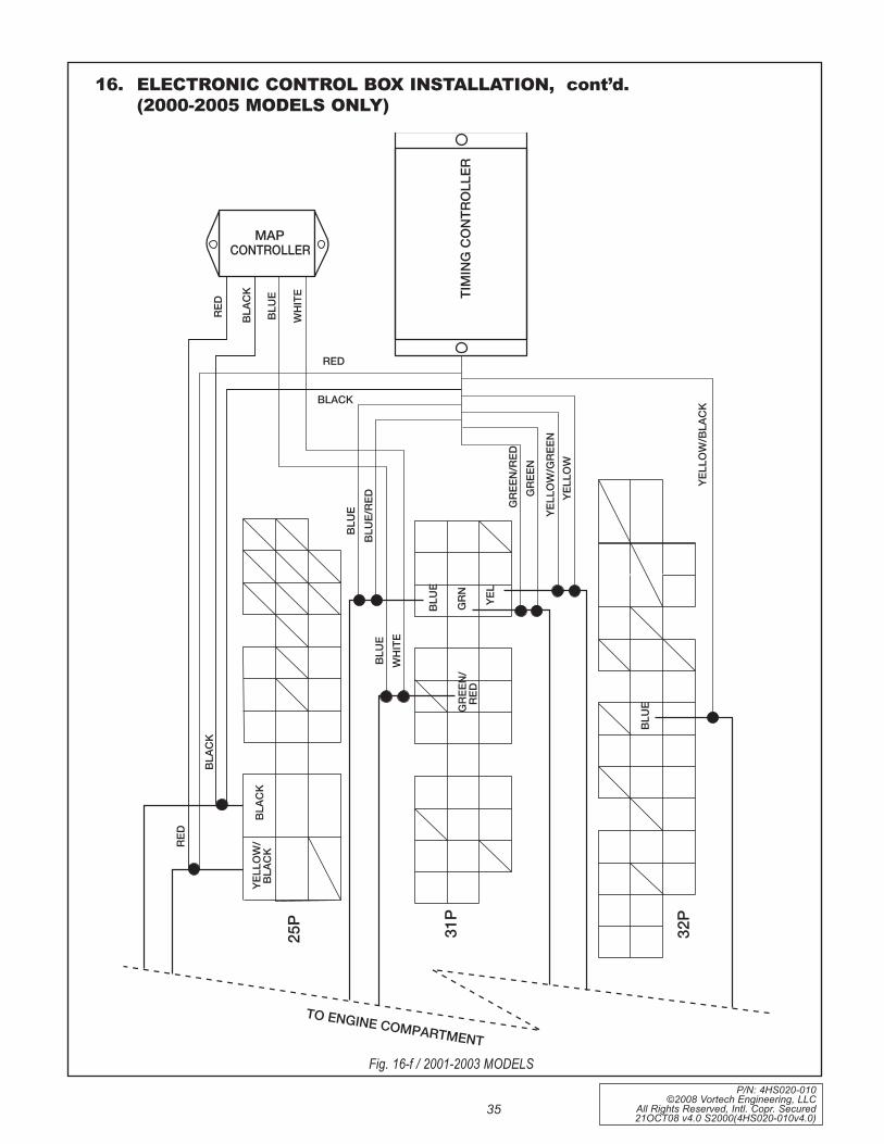
P/N: 4HS020-010 ©2008 Vortech Engineering, LLC
All Rights Reserved, Intl. Copr. Secured 21OCT08 v4.0 S2000(4HS020-010v4.0)
35
16. ELECTRONIC CONTROL BOX INSTALLATION, cont’d. (2000-2005 MODELS ONLY)
Fig. 16-f / 2001-2003 MODELS
YELL
OW
/BLA
CK
TIM
ING
CO
NTR
OLL
ER
MAPCONTROLLER
RED
BLAC
K
BLU
E
WH
ITE
RED
BLACK
BLU
EBL
UE/
RED
GRE
EN/R
EDG
REEN
YELL
OW
/GRE
ENYE
LLO
W
BLU
E
32P
31P
25P
YELL
OW
/BL
ACK
BLAC
K
BLU
EW
HIT
E
GRE
EN/
RED
BLU
E
GRN YE
L
RED
BLAC
K
TO ENGINE COMPARTMENT

P/N: 4HS020-010 ©2008 Vortech Engineering, LLC All Rights Reserved, Intl. Copr. Secured 21OCT08 v4.0 S2000(4HS020-010v4.0)
36
16. ELECTRONIC CONTROL BOX INSTALLATION, cont’d. (2000-2005 MODELS ONLY)
Fig. 16-g / 2004-2005 MODELS
YELL
OW
/BLA
CK
TIM
ING
CO
NTR
OLL
ER
RED
BLACK
BLU
EB
LUE/
RED GR
EEN
/RED
GR
EEN
YELL
OW
/GR
EEN
YELL
OW
BLU
E
32P
31P
25P
YELL
OW
/B
LAC
KB
LAC
K
GR
EEN
/R
ED
BLU
E
GR
N
YEL
RED
BLA
CK
TO ENGINE COMPARTMENT
GR
EEN
YELL
OW
FUEL
INJE
CTO
RPL
UG
S

P/N: 4HS020-010 ©2008 Vortech Engineering, LLC
All Rights Reserved, Intl. Copr. Secured 21OCT08 v4.0 S2000(4HS020-010v4.0)
37
A. (Removal prior to kit installation) Disconnect the neg- battery cable if not already done.Remove the driver’s side kick panel and locate the vehicle computer. Disconnect the factory ECU harness from the ECU (three plug connections).
B. Once re-flashed ECU has been received, re-install in the reverse order that it was removed.
17. ECU REINSTALLATION (2006-2008 MODELS ONLY)

P/N: 4HS020-010 ©2008 Vortech Engineering, LLC All Rights Reserved, Intl. Copr. Secured 21OCT08 v4.0 S2000(4HS020-010v4.0)
38
This Page Left Intentionally Blank

P/N: 4HS020-010 ©2008 Vortech Engineering, LLC
All Rights Reserved, Intl. Copr. Secured 21OCT08 v4.0 S2000(4HS020-010v4.0)
39
18. FINAL CHECkA. Reconnect the battery.B. If your vehicle has gone over 20,000 miles
since its last spark plug change, you will need to change the spark plugs now before test driving the vehicle.
C. Check all fittings, nuts, bolts and clamps for tightness. Pay particular attention to oil and fuel lines around moving parts, sharp edges and exhaust system parts. Make sure all wires and lines are properly secured with clamps or tie-wraps.
D. Check all fluid levels, making sure that your tank(s) is/are filled with 91 octane or higher fuel before commencing test drive. Turn the ingnition on to cycle the fuel pump a few times. Check all fuel fittings for leakage.
E. Start engine and allow to idle a few min-utes, then shut off.
F. Recheck to be sure that no hoses, wires, etc. are near exhaust headers or moving parts and for signs of any fluid leakage.
G. PLEASE TAKE SPECIAL NOTE: Operating the vehicle without ALL the sub-assemblies completely and properly installed may cause FAILURE OF MAJOR COMPONENTS.
H. Test drive the vehicle.I. The supercharger belt stretches initially
and will require adjustment in 250 to 400 miles.
J. Periodically, verify that the supercharger pulley bolt is tight. Also verify that the belt is not slipping under boost. (Belt slippage is usually accompanied by a squealing noise at high RPM and a leveling off or fluctuating boost pressure. If belt slippage occurs, tighten tensioner.)
K. Read the Street Supercharger System Owner's Manual and RETURN THE Warranty REGISTRATION FORM within thirty (30) days of purchasing your super-charger system to qualify.
Fig. 18-a
For internally lubricated V3 units onlyThis supercharger has been factory pre-filled with special Vortech synthetic lubricant. Oil does not need to be added to a brand new unit; however a fluid level check should be performed.Prior to operating the supercharger on the vehicle and after installation onto the vehicle:Remove the factory installed flat-head brass shipping plug (not the dipstick) from the top of the supercharg-er case. Replace the sealed shipping plug with the supplied “vented” plug. Do not operate the super-charger without it. Check the supercharger fluid level.
Fluid level checking procedure: 1. Ensure that the .06” copper sealing washer is located on the dipstick base. 2. Thread the clean dipstick into the supercharger unit it seats. 3. Once the dipstick has seated, remove the dipstick from the unit. Fluid should register in the crosshatched area on the dipstick. 4. DO NOT OVERFILL!!! Drain excess fluid the unit if it is above the maximum level on the dipstick.Check the fluid level using the dipstick at least every 2,500 miles.Initial supercharger fluid change must be performed at 2,500 miles. The supercharger fluid must be changed at least every 7,500 miles.Drain the fluid, refill the unit with 4 oz. of Vortech V3 lubricating fluid and then confirm proper oil level us-ing the dipstick. DO NOT OVERFILL!!!
WARNING: Use of any other fluid other than the special Vortech lubri-cant will void the warranty and may cause component failure.

1650 PACIFIC AVENUE • CHANNEL ISLANDS, CA 93033-9901 • (805) 247-0226FAX (805) 247-0669 • www.vortechsuperchargers.com • M-F 8:00 AM - 4:30 PM PST
®
ENGINEERING, LLC