Engineering guide to emergency planning for UK … · Defra Research Contract: Reservoir Safety...
89
Defra Research Contract: Reservoir Safety Advice ENGINEERING GUIDE TO EMERGENCY PLANNING FOR UK RESERVOIRS Volume 1 of 3 : Main Guide Draft for informal consultation Job Number 0022203/ 206 Rev A04 June 2006 Jacobs Babtie Thorncroft Manor, Dorking Road, Leatherhead, Surrey KT22 8JB Tel 01372 863613 Fax +01372 863602
Transcript of Engineering guide to emergency planning for UK … · Defra Research Contract: Reservoir Safety...

Defra Research Contract: Reservoir Safety Advice ENGINEERING GUIDE TO EMERGENCY PLANNING FOR UK RESERVOIRS Volume 1 of 3 : Main Guide Draft for informal consultation Job Number 0022203/ 206 Rev A04 June 2006 Jacobs Babtie Thorncroft Manor, Dorking Road, Leatherhead, Surrey KT22 8JB Tel 01372 863613 Fax +01372 863602

ENGINEERING GUIDE TO EMERGENCY PLANNING FOR UK RESERVOIRS RESERVOIR SAFETY ADVICE DRAFT GUIDE : VOLUME 1 DEFRA RESEARCH CONTRACT
15/06/2006 i
VOLUME PLAN Volume
1 Main Guide Main Guide Appendix A : Emergency Planning generally Appendix B : Detailed issues regarding hydraulic modelling Appendix C : Scenario Planning in relation to possible emergencies at a dam Appendix D : Possible template for off-site plan
2 Completed examples of elements of reservoir flood plan- A4 Appendix E : Rapid Impact assessment Appendix F.1 : Standard Impact assessment (A4 plan) Appendix G : On-site Plan Example A (owner of single dam) Appendix H : On-site Plan Example B (owner of many dams) Appendix J : External Interface Plan Appendix K : Statement by Qualified Civil Engineer
3 Completed examples of elements of reservoir flood plan- A3 Appendix F.2 : Standard Impact assessment (A3 maps and tables)
The authors of this report are employed by Jacobs Babtie. The work reported herein was carried out under a Contract placed on 6th September 2002 by the Secretary of State for the Environment, Food and Rural Affairs. Any views expressed are not necessarily those of the Secretary of State for the Environment, Food and Rural Affairs. © Crown copyright 2006.

ENGINEERING GUIDE TO EMERGENCY PLANNING FOR UK RESERVOIRS RESERVOIR SAFETY ADVICE DRAFT GUIDE : VOLUME 1 DEFRA RESEARCH CONTRACT
15/06/2006 ii
CONTENTS
PREFACE VII
DISCLAIMER VIII
ACKNOWLEDGEMENTS VIII
1 INTRODUCTION 1 1.1 Objective 1 1.2 Principles of Emergency planning 1 1.3 Interface between reservoir flood plans and other emergency planning 1 1.4 Overview of reservoir flood plans in relation to reservoir safety 2 1.5 Guidance to Panel Engineers 2
2 SPECIFICATIONS FOR FLOOD PLANS 4 Summary of this Section 4 2.1 Extracts from Water Act 2003 of sections relevant to reservoir flood plans 4
2.1.1 Clauses 77 to 79 4 2.1.2 Explanatory Notes in Water Act 2003 6
2.2 Defra Specification of “Matters to be included” under Section 12A(2)(a)) of Reservoirs Act 1975 (as amended by Water Act 2003) 7 2.2.1 General 7
2.2.1.1 Principles 7 2.2.1.2 Definitions 7 2.2.1.3 Elements of a reservoir flood plan 8 2.2.1.4 Cascades of reservoirs (Domino effect) 9 2.2.1.5 Content of reservoir flood plan 11 2.2.1.6 Maintenance of reservoir flood plans 12 2.2.1.7 Examination of reservoir flood plans 12 2.2.1.8 Distribution of accepted version of a reservoir flood plan 13
2.2.2 Schedule 1 : Impact assessment 14 2.2.3 Schedule 2 : On-site plan 15 2.2.4 Schedule 3 : External Interfaces plan 17
2.3 Technical Specification under Section 12A (2)(b) of the Reservoirs Act 1975 (as amended by the Water Act 2003) 18 2.3.1 Standard analysis 18 2.3.2 Rapid method of analysis 20 2.3.3 GIS Format suitable for use by Category 1 Respondents 20
3 SCHEDULE 1 : IMPACT ASSESSMENT 21 Summary of this Section 21 3.1 Objectives, scope and administration of impact assessment 21
3.1.1 Objectives 21 3.1.2 Scope 22 3.1.3 Administration 22
3.2 Scenarios modelled in impact assessment 22 3.2.1 General 22 3.2.2 Uncertainties in extent of inundation due to dam failure 22
3.2.2.1 Release of water from reservoir 22 3.2.2.2 Effect of downstream infrastructure embankments 22 3.2.2.3 Incremental damage caused by dam failure 23
3.2.3 Standard dam breach analysis scenarios 24 3.2.3.1 Background 24 3.2.3.2 Definition 24 3.2.3.3 Commentary – breach assumptions 24 3.2.3.4 Commentary – flood detention reservoirs 25 3.2.3.5 Commentary - effect of infrastructure embankments 25 3.2.3.6 Downstream limit of modelling 26

ENGINEERING GUIDE TO EMERGENCY PLANNING FOR UK RESERVOIRS RESERVOIR SAFETY ADVICE DRAFT GUIDE : VOLUME 1 DEFRA RESEARCH CONTRACT
15/06/2006 iii
3.2.4 Area to be evacuated in event of imminent dam failure 30 3.2.5 Additional scenarios 31 3.2.6 Information provided in reservoir specific assessment 31
3.3 Dam Break Discharges and critical flow paths 31 3.3.1 Introduction 31 3.3.2 Embankment dams 32 3.3.3 Concrete Dams 32 3.3.4 Service Reservoirs 33 3.3.5 Cascades 33 3.3.6 Information provided in reservoir specific assessment 34
3.4 Methodology for Hydraulic Routing 34 3.4.1 General 34 3.4.2 Level of analysis 34 3.4.3 Data Requirements 35 3.4.4 Transportation embankments across flow path 37 3.4.5 Roughness coefficients 37 3.4.6 Information provided in reservoir specific assessment 37
3.5 Consequence assessment 38 3.5.1 Introduction 38 3.5.2 Level of analysis and data requirements 38 3.5.3 Information provided in site specific assessment 40
3.6 Results of impact assessment 44 3.7 Impact on Infrastructure 44
3.7.1 Severing of transportation links 44 3.7.2 Possible use of infrastructure for attenuating flood wave 44
3.8 Maintenance of the Impact assessment 44
4 SCHEDULE 2 : ON-SITE PLAN 46 Summary of this Section 46 Data Requirements 46 Detail of Plan 46 4.1 Objectives, scope and administration of the on-site plan 47
4.1.1 Objectives 47 4.1.2 Scope 47 4.1.3 Administration of the On-site plan 47
4.1.3.1 General 47 4.1.3.2 Sensitive information 48
4.2 Management of emergency by the Undertaker 48 4.2.1 Undertaker’s procedures and authorised personnel 49 4.2.2 External communication 50 4.2.3 Checklist for those attending the emergency 51
4.3 Description of the reservoir and retaining dam(s) 54 4.3.1 Situation 54 4.3.2 Detailed records 54 4.3.3 Physical dimensions and features 55 4.3.4 Other facilities relevant to on-site operations 55 4.3.5 Access to reservoir 55 4.3.6 Communications at the reservoir site 56 4.3.7 Welfare facilities 56 4.3.8 Normal Operation 56
4.4 Actions by undertaker on site 57 4.4.1 Situation assessment 57
4.4.1.1 General 57 4.4.1.2 Serious incident at reservoir higher up cascade 58 4.4.1.3 Health and Safety 59 4.4.1.4 Potential Environmental impacts 59
4.4.2 Undertaker’s resources relevant to on-site activities 59 4.4.3 Reservoir drawdown 60
4.4.3.1 General 60 4.4.3.2 Capacity for emergency drawdown to avert dam failure 60

ENGINEERING GUIDE TO EMERGENCY PLANNING FOR UK RESERVOIRS RESERVOIR SAFETY ADVICE DRAFT GUIDE : VOLUME 1 DEFRA RESEARCH CONTRACT
15/06/2006 iv
4.4.3.3 Rate of drawdown to be utilised at time of incident 62 4.4.3.4 Inflows from direct catchment 63 4.4.3.5 Ability to divert or block inflows 64 4.4.3.6 Practical issues relating to emergency drawdown 65
4.4.4 Other measures 65 4.4.5 Off-site impacts of site activities 65 4.4.6 Assistance from external organisations with on-site measures 66
4.5 Measures at other installations 66 4.6 Maintenance of the On-site plan 67
4.6.1 Training of staff 67 4.6.2 Periodic testing of equipment 67 4.6.3 Exercising 68 4.6.4 Review and updating of the plan 68
4.7 Other issues 69
5 SCHEDULE 3 : EXTERNAL INTERFACES PLAN 70 Summary of this Section 70 5.1 Objectives, scope and administration of the plan 70
5.1.1 Objectives 70 5.1.2 Scope 70 5.1.3 Administration of the plan 70
5.2 Notification by Undertaker of a serious incident at a reservoir 71 5.2.1 Information to be provided to Local Resilience Forum 71 5.2.2 Available relevant documents 71
5.3 Management of a serious incident by Undertaker 72 5.3.1 Undertaker’s procedures and authorised personnel 72 5.3.2 Communications 72 5.3.3 Undertaker’s Resources relevant to off-site activities 72
5.4 Maintenance of the External Interface Plan 73 5.4.1 Training and Exercising 73 5.4.2 Review and updating of the plan 74
5.5 Other issues 74
6 REFERENCES 75
7 TERMINOLOGY 76 7.1 Acronyms 76 7.2 Definitions 78
APPENDIX A : EMERGENCY PLANNING GENERALLY 81 Summary of this Section 81 A.1 Principles of Emergency planning 81
A.1.1 General 81 A.1.2 Extendibility 81 A.1.3 Maintenance of emergency plans 82 A.1.4 Training and exercising 82
A.2 Planning for dam break flooding 83 A.2.1 Differnces between fluvial and dam break flooding 83 A.2.2 Proportionate cost 84
A.3 Role of the emergency services and local authority 84
APPENDIX B : DETAILED ISSUES REGARDING HYDRAULIC MODELLING 86 Summary of this Section 86 B.1 Possible scenarios for release of water from reservoirs 86 B.2 Program Types 88
B.2.1 Hydraulic modelling 88 B.2.2 Flood Mapping 88
B.3 Program Requirements for Dam-Break Analysis 90 B.4 Commercially available software 90
B.4.1 Hydraulic modelling 90

ENGINEERING GUIDE TO EMERGENCY PLANNING FOR UK RESERVOIRS RESERVOIR SAFETY ADVICE DRAFT GUIDE : VOLUME 1 DEFRA RESEARCH CONTRACT
15/06/2006 v
B.4.2 Flood Mapping 91 B.5 Ground model 92
B.5.1 Ground elevation data 92 B.5.2 Transportation embankments, structures and channel cross sections 95
B.6 Model Cross Section and Reach Specification 95 B.7 Model Boundary Conditions and Steady State Conditions 96 B.8 Model calibration and verification 97 B.9 Flood Risk Mapping 97
APPENDIX C : SCENARIO PLANNING IN RELATION TO POSSIBLE EMERGENCIES AT A DAM 99 C.1 Prompt sheet for assessment of measures to prevent or delay failure 99 C.2 Sinkholes above reservoir level 100 C.3 Spillway blocked by trash 101 C.4 Serious internal erosion incident 102
APPENDIX D : POSSIBLE TEMPLATE FOR A SITE SPECIFIC OFF-SITE PLAN 104 Preface to this Appendix 104 D.1 General 105
D.1.1 Aim of Plan 105 D.1.2 Scope of Plan 105 D.1.3 Risk Assessment 105 D.1.4 Plan Validation and Training 106
D.2 Roles and Responsibilities 106 D.2.1 Multi-Agency Strategic Co-ordinating Group (4.1-4.111) 106 D.2.2 Police (3.1 – 3.5) 107 D.2.3 Fire and Rescue Service (3.6-3.8) 107 D.2.4 Health bodies (3.9-3.11) 107 D.2.5 Local Authority (3.25 – 3.29) 107 D.2.6 Environment Agency (3.31 – 3.33) 108 D.2.7 The private sector - Essential service providers (3.50-3.54) 108
Water Company 108 Electricity Distribution Company 108 Gas Network Provider 108
D.2.8 The private sector -Other private sector organisations (3.55-3.57) 108 The Reservoir Undertaker 108
D.3 Coordination and control arrangements 109 D.3.1 Activation and Incident level 109 D.3.2 Multi-agency Gold, Silver and Bronze Controls 109 D.3.3 Other Agencies’ Control Arrangements 109 D.3.4 Public Warning and Information 109
D.4 Action 110 D.5 Appendices to possible off-site plan 111
D.5.A Contact numbers for key players 111 D.5.B Useful Background Information 111 D.5.C Schedule of the Vulnerable 111 D.5.D Schedule of Critical Local Infrastructure 111 D.5.E Schedule of culturally and environmentally sensitive areas 111 D.5.F Specific Contingency Arrangements 111 D.5.G Detailed risk assessment 111 D.5.H Details of plan validation and training arrangements 111 D.5.J Public information arrangements 111 D.5.K Log of plan validation (exercise) and training 111

ENGINEERING GUIDE TO EMERGENCY PLANNING FOR UK RESERVOIRS RESERVOIR SAFETY ADVICE DRAFT GUIDE : VOLUME 1 DEFRA RESEARCH CONTRACT
15/06/2006 vi
List of Tables Table 1.1 : Responsibilities of those involved in reservoir safety.................................................................3 Table 2.1 : Elements of a reservoir flood plan under the Reservoirs Act 1975 (as amended by the Water
Act 2003). ..............................................................................................................................................8 Table 2.2 : Period for preparation and examination of reservoir flood plans............................................13 Table 3.1 : Possible scenarios for effect of transportation embankments on extent of inundation .............23 Table 3.2 : Definition of Standard Dam Breach Analysis Scenarios ..........................................................27 Table 3.3 : Physical factors affecting attenuation of flood wave down valley............................................28 Table 3.4 : Preliminary values of blockage of structures in dam break scenario ........................................30 Table 3.5 : Data required for modelling breach discharge from reservoir ..................................................35 Table 3.6 : Other data required for hydraulic analysis ................................................................................36 Table 3.7 : Level of detail in estimating likely consequences of dam failure .............................................41 Table 3.8 : Alternative sources of data required to quantify consequences of dam failure, and possible
sources.................................................................................................................................................42 Table 3.9 : Indicative frequency of maintenance of impact assessment .....................................................45 Table 4.1 : Data required by Undertaker for preparation of an on-site plan ...............................................46 Table 4.2 : Checklist of processes that will need to be managed ................................................................49 Table 4.3 : Checklist of actions for which lead responsibility should be declared .....................................50 Table 4.4 : Recommended range of Undertaker’s incident level ................................................................52 Table 4.5 : Access in an emergency ............................................................................................................56 Table 4.6 : Occasions for review of failure modes......................................................................................58 Table 4.7 : Indicators of a serious structural problem with a dam ..............................................................58 Table 4.8 : Checklist of possible measures to prevent or delay failure .......................................................59 Table 4.9 : Criteria published in the literature for required capacity for rate of drawdown of reservoirs...61 Table 4.10 : Drawdown arrangements adopted by one major UK reservoir owner ....................................62 Table 4.11 : Factors influencing required capacity for rate of lowering .....................................................62 Table 4.12 : Factors influencing rate of lowering adopted for precautionary drawdown ...........................63 Table 4.13 : Possible levels of exercising of an On-site plan (additional to Table A.1) .............................68 Table 4.14 : Indicative frequency of maintenance of on-site plan ..............................................................69 Table 5.1 : Indicative frequency of maintenance of an external interface plan...........................................73 Table A.1 : Possible methods of exercising of an emergency plan.............................................................83 Table B.1 : Possible scenarios for releases from reservoirs ........................................................................86 Table B.2 : Comparison of different levels of modelling of spatial dimensions.........................................89 Table B.3: Summary of Flood Routing Software.......................................................................................91 Table B.4 : Summary of sources of ground data used in fluvial modelling ................................................93 Table D.1 : Trigger Levels for Implementing the Off-Site Plan to Respond to Potential and Actual Dam
Breaches ............................................................................................................................................110 List of Figures Figure 2.1 : Application of reservoir flood plans to reservoirs and dams in cascade..................................10 Figure 3.1: Illustration of possible effect of downstream inflows on peak flood flow ...............................26 Figure 3.2 : Flow chart to model transportation embankment across flow path .........................................29 Figure 3.3 Overall Consequence class (as Sheet 11.2 of Interim Guide to QRA, ICE, 2004) ....................39 Figure 3.4: Flow chart for estimation of consequences of am failure .........................................................39 Figure 4.1 : Example Flow chart for on-site assessment of the seriousness of an incident.........................53 Figure A.1 : Need for a proportionate approach to management of the risk of dam failure .......................84

ENGINEERING GUIDE TO EMERGENCY PLANNING FOR UK RESERVOIRS RESERVOIR SAFETY ADVICE DRAFT GUIDE : VOLUME 1 DEFRA RESEARCH CONTRACT
15/06/2006 vii
PREFACE The purpose of this Engineering Guide to Emergency Planning for UK Reservoirs is to provide guidance to assist the undertaker and his advisors in the preparation of an emergency plan (reservoir flood plan) for his reservoirs, as one of the tools used to manage risk. It is directed principally at those dams in England where the Secretary of State directs that a (reservoir) flood plan is required under Section 12A of the Reservoirs Act 1975 (as amended by the Water Act 2003), but may be used for any reservoir (including those which do not come under the provisions of the Reservoirs Act 1975). Any Direction would refer to a specification of “matters to be included”, a draft of this specification being reproduced with commentary in Section 2 of the main Guide. In addition it will require the impact assessment element of a reservoir flood plan to be prepared in accordance with a technical specification, which is also given in Section 2 of this Guide. The specifications have been prepared following the principles of a permissioning regime, where the responsibility for managing risk lies with the owner of the installation. Reservoir flood plans under the Reservoirs Act 1975 (as amended by the Water Act 2003) will comprise three elements covering the assessment of the potential consequences of failure in terms of both the extent of inundation and likely loss of life, on-site activities by the Undertaker, and the essential communication with the Emergency Services. They will not cover off-site activities. It is anticipated that the latter would be covered by Category 1 responders under the Civil Contingencies Act, 2004. The Guide comprises
• Section 1 setting out the objectives of Emergency Planning • Section 2 providing commentary on the specifications under Section 77 (12A(2)(a)) of the Water
Act 2003 • Sections 3 to 5 providing guidance on the preparation of the various elements of a reservoir flood
plan, as defined in the Schedules under Section 77 (12A(2)(a)) of the Water Act • Sections 6 and 7 provide References and Terminology • Appendix A : Emergency Planning generally • Appendix B : Detailed issues regarding hydraulic modelling • Appendix C : Scenario Planning in relation to possible emergencies at a dam • Appendix D : Possible template for off-site plan • Appendices E to J : Completed examples of elements of a reservoir flood plan (in Volumes 2,
although with the A3 size document in Volume 3) • Appendix K: Completed example of the statement by a Qualified Civil Engineer, supporting the
plan It is noted that the owner of any installation, including undertakers of dams, which may pose a threat to his staff or the public has a responsibility to manage that installation such that the risk is reduced to an acceptable level. Risk reduction measures can include physical works, improved surveillance and maintenance as well as emergency planning. The purpose of legislation and this Guide is to highlight the undertaker’s responsibilities and provide a check that emergency planning is in place; it is not to provide a prescriptive formula. Responsibility for the safety of the reservoir rests with the undertaker. In particular although service reservoirs are unlikely to be required to have reservoir flood plans, the onus remains with the Undertaker to make his own assessment of the risks and thus determine whether the cost of some or all elements of a reservoir flood plan would be a proportionate risk reduction measure for that service reservoir.

ENGINEERING GUIDE TO EMERGENCY PLANNING FOR UK RESERVOIRS RESERVOIR SAFETY ADVICE DRAFT GUIDE : VOLUME 1 DEFRA RESEARCH CONTRACT
15/06/2006 viii
DISCLAIMER Neither the authors, publishers or Defra shall be liable (whether in contract, tort (including negligence) or breach of statutory duty or otherwise) for any loss or damage suffered arising out of or in connection with any use of or reliance upon the contents of this document including direct loss, business interruption, loss of production, profits, contracts, goodwill or anticipated savings, loss arising from third party claims or any indirect or consequential loss (whether or not foreseeable). However, nothing in this disclaimer shall exclude or limit liability for death or personal injury resulting from the proven negligence of any person mentioned above or for fraud or any other liability which may not be limited or excluded by law. ACKNOWLEDGEMENTS This Guide was prepared by the following: Individual Role Alan J Brown Project Manager and Panel AR Dam Engineer Jacobs Babtie* John Gosden Overview/Reviewer and Panel AR Dam Engineer Jacobs Babtie* F Julian Smith Principal Hydraulic Modeller Jacobs Babtie* Bernard Kershaw County Emergency Planning Officer Lancashire CC Steve Ridings Senior Emergency Planning Officer Lancashire CC
*previously KBR We acknowledge the contribution to this project from the following, who provided valuable assistance in making information and staff available: British Waterways, Cornwall County Council, Environment Agency, Leeds Council, National Trust, Severn Trent, United Utilities and Yorkshire Water. Steering Group The project benefited from a Steering Group to advise Defra, appointed through the Institution of Civil Engineers Reservoirs Safety Working Group, which comprised: Alex Macdonald – Chairman Jacobs Babtie Andrew Robertshaw Yorkshire Water Services Jonathan Hinks Halcrow (Rev 03 onwards) Tanya Olmeda-Hodge Country Land and Business Association Ian Hope Environment Agency Technical Manager – Reservoir Safety Keith Bates Defra (Sponsor of the Project)

ENGINEERING GUIDE TO EMERGENCY PLANNING FOR UK RESERVOIRS RESERVOIR SAFETY ADVICE DRAFT GUIDE : VOLUME 1 DEFRA RESEARCH CONTRACT
15/06/2006 1
1 INTRODUCTION
1.1 Objective Section 77 of the Water Act, 2003 commences:-
“(1) The Secretary of State may, by written notice served on the undertakers in relation to a large raised reservoir, direct them to prepare a plan (a "flood plan") setting out the action they would take in order to control or mitigate the effects of flooding likely to result from any escape of water from the reservoir. (2) A direction may in particular- (a) specify the matters to be included in the flood plan; (b) require the flood plan to be prepared in accordance with such methods of technical or other analysis as may be specified by the Environment Agency” (The Enforcement Authority for the Reservoirs Act 1975, in accordance with Clause 74 of the Water Act);
The objective of this Guide is to provide the following to assist in the implementation of any Direction by the Secretary of State under Section 77 of the Reservoirs Act 1975 (as amended by the Water Act 2003) as to the requirement for reservoir flood plans under that Act:- a) Guidance to assist the undertaker and his advisors in the preparation of the reservoir flood
plan b) Details of what is “specified” under Section 72(2)(b) of the Water Act 2003 c) Completed examples of the various elements of a reservoir flood plan
1.2 Principles of Emergency planning Emergency planning is increasingly recognised as one of the measures, which when applied systematically, may be used to manage (and reduce) the risk from high hazard installations. Emergency planning may be subdivided into a) Assessing the potential consequences of failure (the “impact assessment”) b) Actions the owner of the high hazard installation takes on his land to prevent or mitigate a
failure (the “on-site” plan) and c) Measures taken on third party and public land to mitigate the effects of a failure (the “off-
site” plan). Further information is provided into the principles of emergency planning in Appendix A.
1.3 Interface between reservoir flood plans and other emergency planning It is anticipated that impact assessments will be prepared on the basis of information readily available to the Undertaker. Thus they would not necessarily include identification of occupants of buildings which could be affected. Similarly there would not normally be contact with the owners of property which could be affected to refine potential consequential damages or emergencies that might occur as a result of reservoir failure (e.g. release of chemicals from inundated factories). These are anticipated as being within the remit of an off-site plan. Similarly the on-site plan would only cover actions that could reasonably be expected of the Undertaker, for example being on land owned or occupied by him. Nevertheless, in producing his reservoir flood plan the Undertaker is encouraged to promote dialogue with Category 1 responders to mutually improve the quality of emergency planning for reservoirs owned by the Undertaker. Where the Undertaker is a Category 2 responder under the

ENGINEERING GUIDE TO EMERGENCY PLANNING FOR UK RESERVOIRS RESERVOIR SAFETY ADVICE DRAFT GUIDE : VOLUME 1 DEFRA RESEARCH CONTRACT
15/06/2006 2
Civil Contingencies Act 2004, then he would have a role under that legislation additional to that under the Reservoirs Act 1975 (as amended by the Water Act 2003).
1.4 Overview of reservoir flood plans in relation to reservoir safety The responsibilities of the various organisations and individuals involved in the safety of reservoirs are summarised in Table 1.1. Attention is drawn to the principle of a permissioning regime, whereby a) the organisation which creates the hazard has a legal duty to manage the risk through the
preparation of a safety case which describes how the risk is managed. The safety case involves the following steps:
• Identify the hazards • Assess the risks • Develop effective control measures in a coherent whole (i.e. an integrated
approach) • Keep a current documentary record.
b) The general approach to regulation is that a goal setting framework is preferable to defining prescriptive standards as it makes duty holders think for themselves. This flexibility leads to methods of risk control being tailored to particular circumstances.
Emergency planning should form part of the Undertaker’s risk control measures at a reservoir, being active and ongoing control measures which are documented in flood plans. With regard to the wider issues of the education of the public and others to appreciate the risk from reservoirs and the measures being taken to manage these risks, this is the responsibility of all those involved in the management of reservoir safety. This is necessary if societal decisions on the tolerability of risk are to be informed decisions.
1.5 Guidance to Panel Engineers It is noted that emergency planning is one of the tools which can be used to manage risk posed by a reservoir, the other tools comprise physical works and surveillance. As such it is anticipated that Inspecting Engineers would include
a) a review of the reservoir flood plan as part of any Section 10 Inspection, and if the reservoir flood plan is found to be inadequate recommendations covering the
• on-site plan could be included as matters in the interests of safety • the impact assessment and external interfaces could be included in relation to the
adequacy of records for the reservoir b) in directions under Section 11(2) of the Reservoirs Act 1975 that information to be
recorded should include both updates of the reservoir flood plan and exercising of the various elements of the reservoir flood plan
c) in matters noted for the Supervising Engineer under Section 12(2) of the Reservoirs Act 1975 the need to check the ongoing maintenance of the reservoir flood plan
In terms of the maintenance of reservoir flood plans, it is anticipated that the Supervising Engineer would check that each element of the plan is subject to validation, training, exercising and review and revision at the frequency specified in the reservoir flood plan. Where the maintenance specified in the plan was not occurring, then this should be reported to the enforcement authority under Section 20 (4)(e)(i) of the Reservoirs Act 1975.

ENGINEERING GUIDE TO EMERGENCY PLANNING FOR UK RESERVOIRS RESERVOIR SAFETY ADVICE DRAFT GUIDE : VOLUME 1 DEFRA RESEARCH CONTRACT
15/06/2006 3
Table 1.1 : Responsibilities of those involved in reservoir safety
Organisation Responsibility Undertaker (Reservoir owner)
Responsibility for managing the risk lies firmly with the owner of the hazardous installation and the duty of care they owe to everyone who is put at risk by the existence of that hazard. This follows, for example the common law case of Rylands v Fletcher (1868) LR 3 HL 330, and also Principles 3 and 6 of permissioning regimes (Policy Statement by HSC, available at www.hse.gov.uk/enforce/permissioning.pdf). This will apply irrespective of any standard or guide that may be defined by Government or any other party as to tolerability levels. The reasonableness of the actions of the Undertaker in managing any risk would in the last resort be tested and determined through courts of law.
Government Government is responsible for the legislative framework which seeks to ensure public safety through certain minimum requirements on Undertakers. For reservoirs this is through the Reservoirs Act 1975. Defra, along with other agencies, in its role as policy lead, promotes guidance on technical standards through the promotion of research and Engineering Guides. Defra, liaising with Scottish and Welsh Government bodies, would look to the Reservoir Safety Working Group (RSWG), appointed by the Institution of Civil Engineers to advise it on the appropriateness of issuing new guidance to panel engineers (as was carried out recently on extreme rainfall). The RSWG is representative of the dam industry in that it comprises panel engineers (with links to the Reservoirs Committee and the British Dam Society), Undertakers and the enforcement authority. Advice can also be obtained from technical research contractor(s), either in place or appointed to advise on specific issues. Government Ministers can therefore satisfy themselves that the guidance and other information issued to the engineers they have appointed stands up to contemporary technical scrutiny and is appropriate.
Qualified Civil Engineers
Assessment of safety at individual reservoirs is through certification of new reservoirs by Construction Engineers, and periodic inspections by Inspecting Engineers and annual statements by Supervising Engineers of existing reservoirs, termed collectively Qualified Civil Engineers. These are appointed to panels following Section 4 of the Reservoirs Act by the Secretary of State after consultation with the President of the Institution of Civil Engineers advised by the “Reservoirs Committee”. These engineers use their judgement as informed by guidance/ technical standards which have evolved from collective experience and research to advise the Undertaker on minimum acceptable standards. Inspecting Engineers have the power to require “works in the interests of safety”.
Enforcement authority
The enforcement authority has an executive role in ensuring that safety works are executed and other requirements of the Reservoirs Act 1975 are complied with. It is noted that their function as Enforcement Authority as defined in Section 2(3) of the Reservoirs Act 1975 is limited to enforcement of process rather than determining technical standards.
Society (including those at risk if a dam failed)
Tolerable is defined as “a willingness to live with a risk so as to secure certain benefits and in the confidence that the risk is one that is worth taking and that it is being properly controlled” (Reducing risk, protecting people, HSE, 2001, page 3). The balance between risk and benefits (tolerability) is ultimately determined by society, including for example balancing the cost of water against the risk posed by water supply reservoirs. Society’s views are voiced through representation in parliament and executive government

ENGINEERING GUIDE TO EMERGENCY PLANNING FOR UK RESERVOIRS RESERVOIR SAFETY ADVICE DRAFT GUIDE : VOLUME 1 DEFRA RESEARCH CONTRACT
15/06/2006 4
2 SPECIFICATIONS FOR FLOOD PLANS Summary of this Section
This section first reproduces the relevant text of the primary legislation on reservoir flood plans (the Reservoirs Act 1975 (as amended by the Water Act 2003)), followed by the two specifications produced under Section 77 (12A (2)) of this Act. The text of each specification is followed by commentary, apart from the three schedules of the contents of each element of a reservoir flood plan, for which commentary is given within the section of the Guide covering the relevant element of the reservoir flood plan.
2.1 Extracts from Water Act 2003 of sections relevant to reservoir
flood plans
The text of the Water Act 2003, together with explanatory notes, can be found at www.legislation.hmso.gov.uk/acts/acts2003/20030037.htm.
2.1.1 Clauses 77 to 79
77 Flood plans: large raised reservoirs After section 12 of the Reservoirs Act 1975 there is inserted- "Flooding 12A Flood plans: large raised reservoirs (1) The Secretary of State may, by written notice served on the undertakers in relation to a large
raised reservoir, direct them to prepare a plan (a "flood plan") setting out the action they would take in order to control or mitigate the effects of flooding likely to result from any escape of water from the reservoir.
(2) A direction may in particular- (a) specify the matters to be included in the flood plan; (b) require the flood plan to be prepared in accordance with such methods of technical or other analysis as may be specified by the Environment Agency; (c) require the flood plan, or any information about the matters contained in it, to be given to the Environment Agency at such time or times as may be directed by that Agency or by the Secretary of State; (d) require a copy of the flood plan to be sent to such persons as may be specified in the direction; (e) require publication of the flood plan, in such manner as may be specified in the direction, for the purpose of bringing the matters contained in the flood plan to the attention of persons likely to be interested.
(3) Before giving a direction under this section the Secretary of State shall consult-
(a) the undertakers concerned; (b) the Environment Agency; (c) if the reservoir concerned is in England, the county council, metropolitan district council or London borough council in whose area the reservoir is situated; (d) if the reservoir concerned is in Wales, the county council or county borough council in whose area the reservoir is situated; (e) such persons appearing to the Secretary of State to represent the emergency services in the area where the reservoir is situated; and (f) such other persons (if any) as the Secretary of State considers appropriate.

ENGINEERING GUIDE TO EMERGENCY PLANNING FOR UK RESERVOIRS RESERVOIR SAFETY ADVICE DRAFT GUIDE : VOLUME 1 DEFRA RESEARCH CONTRACT
15/06/2006 5
(4) If-
(a) the functions of the Secretary of State under the preceding provisions of this section are transferred to the National Assembly for Wales so far as exercisable in relation to Wales; (b) no direction has been given by the Assembly under subsection (1) above in relation to a reservoir in Wales; and (c) it appears to the Secretary of State that it is necessary or expedient in the interests of public safety in England that such a direction be given, he may give a direction under that subsection in relation to that reservoir.
(5) This section is subject to section 12B below." 78 National security (1) In section 2 of the Reservoirs Act 1975 (c. 23) (registration of reservoirs and
enforcement of Act, etc), after subsection (2) there is inserted- "(2A) If it appears to the Secretary of State that the inclusion of any information in the
register maintained under subsection (2) above by the Environment Agency would be contrary to the interests of national security, he may direct the Agency not to include that information in the register."
(2) After section 12A of that Act (which is inserted by section 77 of this Act) there is inserted-
"12B Flood plans and national security
(1) If it appears to the Secretary of State that in the interests of national security any person or class of persons referred to in any one or more of paragraphs (a) to (e) of section 12A(3) above should not be consulted about a proposed direction, he may treat that subsection as not referring to that person or to that class of person.
(2) In relation to any reservoir (whether a large raised reservoir or not, as the case may be) the Secretary of State may, by written notice served on the undertakers, require them not to publish, or not to publish except as specified in the notice-
(a) a flood plan prepared by them pursuant to a notice given under section 12A above;
(b) any corresponding plan prepared by them other than pursuant to such a notice, and a notice under this subsection may also require the undertakers to withhold access to any such plan from any person except as specified in the notice."
79 Offences (1) Section 22 of the Reservoirs Act 1975 (c. 23) (criminal liability of undertakers and their employees) is amended as follows. (2) In subsection (1), the word "or" at the end of paragraph (a) is omitted, and at the end of paragraph (b) there is inserted "or (c) the undertakers fail to comply with a direction under section 12A above;". (3) After subsection (1) there is inserted-

ENGINEERING GUIDE TO EMERGENCY PLANNING FOR UK RESERVOIRS RESERVOIR SAFETY ADVICE DRAFT GUIDE : VOLUME 1 DEFRA RESEARCH CONTRACT
15/06/2006 6
"(1A) If the undertakers fail without reasonable excuse to comply with a notice under section 12B above, they shall be guilty of an offence and liable-
(a) on summary conviction, to a fine not exceeding the statutory maximum; (b) on conviction on indictment, to imprisonment for a term not exceeding two years, or
to a fine, or to both."
It is noted that this is the only place in the Reservoirs Act 1975 where an offence is a criminal offence.
2.1.2 Explanatory Notes in Water Act 2003
Section 77: Flood plans: large raised reservoirs. The Reservoirs Act 1975 makes provision in respect of escapes of water from large raised reservoirs. The emphasis of the current legislation is on prevention of escapes. But with uncertainties over the future implications of climate change and rainfall patterns further flexibility within this safety legislation, in the Government's view, should be available. Some reservoir owners already prepare flood plans voluntarily. This section enables the Secretary of State, after consultation with all interested parties, to issue a direction to the owner of a large raised reservoir in England or Wales requiring the preparation and dissemination of such a plan. Under section 77(4), the Secretary of State may also issue directions to reservoir undertakers in Wales where the Assembly has not itself done so but where it is considered necessary in the interests of public safety in England. Section 78-79: National security and offences. This section provides for the exclusion from the registers, maintained under section 2 of the 1975 Act of information that is prejudicial to the interests of national security. It also imposes restrictions on consultation and publication arrangements in section 77 where the Secretary of State (or Assembly) considers it necessary to do so in the interests of national security. The restrictions on publication may extend to flood plans other than those prepared under section 77 and restrictions may also limit access to any flood plans. Failure by an undertaker to comply with a notice issued under this section will be a criminal offence (under section 79).

ENGINEERING GUIDE TO EMERGENCY PLANNING FOR UK RESERVOIRS RESERVOIR SAFETY ADVICE DRAFT GUIDE : VOLUME 1 DEFRA RESEARCH CONTRACT
15/06/2006 7
2.2 Defra Specification of “Matters to be included” under Section 12A(2)(a)) of Reservoirs Act 1975 (as amended by Water Act 2003)
2.2.1 General 2.2.1.1 Principles
1. A Flood Plan is required for situations which could lead to a large release of water from a reservoir (or a group of reservoirs) that could pose a threat to the public and property downstream (e.g. failure of a dam, accidental or deliberate releases of water from large diameter valves and gates).
2. The objective of a flood plan is to
• minimise the probability of failure in the event of a structural problem at a dam, • contribute to minimising the loss of life and injury to members of the public in the
potential inundated zone, both through the direct results of the dambreak and its consequential effects
3. The Undertaker shall make and test arrangements for managing these situations and
mitigating their consequences as part of ensuring the risk from the reservoir is managed and maintained at a tolerable level. This shall include preparing, and maintaining, a current documentary record of these arrangements in the form of one flood plan for each reservoir.
As described below the reservoir flood plan is essentially a document setting out actions by the Undertaker on land owned or occupied by him. It may therefore not include off-site actions on land owned by others. However, Water and Sewerage Operators are Category 2 Responders under the Civil Contingencies Act 2004, and have responsibilities to work within a framework of information sharing and co-operation in regard to off-site planning. Whilst not all Reservoir Undertakers are Category 2 Responders it is recommended that those who are not adopt the principles of information sharing and co-operation. 4. The flood plan will normally be prepared, and reviewed (and updated or modified where
appropriate), in conjunction with Section 10 Inspections under the Reservoirs Act 1975, as part of an integrated risk management strategy for the reservoir.
5. This Specification provides details of the required minimum content, and the timescale for
submission of the flood plan. The Undertaker, as duty holder responsible for the reservoir, may adopt more detailed plans, following the principles of permissioning regimes set out in “Regulating Higher Hazard Industries” (HSE, 2000)
2.2.1.2 Definitions
6. Definitions shall be as given in Schedule 1 to the Reservoirs Act and as follows Term Explanation Cascade Where two or more reservoirs are located adjacent to each other such that
the failure of one dam retaining one reservoir could lead to the failure of a dam retaining another reservoir (the domino effect). A cascade may include reservoirs on more than one upstream tributary. Where the valley between two reservoirs includes a community then for the purposes of this specification they shall not be considered as part of the same cascade.
Category 1 and 2 responders
As defined in Schedule 1 of the Civil Contingencies Act 2004
Flow path A credible route by which discharges from the reservoir may flow in the event of a breach. For impounding reservoirs this would generally be the

ENGINEERING GUIDE TO EMERGENCY PLANNING FOR UK RESERVOIRS RESERVOIR SAFETY ADVICE DRAFT GUIDE : VOLUME 1 DEFRA RESEARCH CONTRACT
15/06/2006 8
Term Explanation watercourse or valley across which the dam is built. For non-impounding reservoirs and service reservoirs it is likely to be more complex, and may be influenced by the geometry of buildings and transport infrastructure as well as topography.
(Reservoir) flood plan The elements described in this Specification.
Local authority As defined in Schedule 1 of the Civil Contingencies Act 2004
2.2.1.3 Elements of a reservoir flood plan
7. The flood plan at a reservoir will consist of three elements, as shown in Table 2.1
Table 2.1 : Elements of a reservoir flood plan under the Reservoirs Act 1975 (as amended by the Water Act 2003).
Element Title Purpose Minimum requirements
I Impact assessment An assessment of the likely impact in the event the dam failed releasing the water retained in the reservoir, both hydraulically and in consequences to people and property. Determination of the Consequence Class of the dam, which is necessary to determine the proportionate level of detail required for emergency planning
Schedule 1
II On-site plan The measures the Undertaker could take on his land to avert or mitigate the failure of the dam in the event of a structural problem developing.
Schedule 2
III External Interfaces plan
A plan to facilitate off-site activities in the event of a declaration of emergency at a dam, including
a) Defining and periodically testing channels of communication from the Undertaker to nominated members of the Local Resilience Forum
b) Defining the Undertaker’s resources which could be used to assist in dealing with an emergency.
Schedule 3
It is the responsibility of the Undertaker to prepare all of the above. It is anticipated that off-site planning for reservoir failure will be by Category 1 responders, under the co-ordination of the Local Resilience Forum, as required by the Civil Contingencies Act and associated documents. This is discussed further in Appendices A and D.
8. Where a reservoir is retained by more than one dam or structure, or a long dam, such that a
breach of the reservoir could be into separate flow paths, depending on which dam or section of a dam has failed, then a separate impact assessment will be required for each flow path along which the reservoir could breach. The impact assessments for each flow path, shall be attached together to form the impact assessment for the reservoir.
One reservoir flood plan is required for reservoir, including all flow paths into which a reservoir could breach. Where two flow paths join a short distance downstream of the reservoir with no intervening property at risk they may be considered as one flow path, although the flood mapping should include flooding on both flow paths.

ENGINEERING GUIDE TO EMERGENCY PLANNING FOR UK RESERVOIRS RESERVOIR SAFETY ADVICE DRAFT GUIDE : VOLUME 1 DEFRA RESEARCH CONTRACT
15/06/2006 9
For impounding reservoirs the flow path would generally be the valley across which the dam is built. For non-impounding and service reservoirs with no well defined watercourses, judgment may be required as to when more than one impact analysis is required, because breaches of different sections of the dam may breach into different flow paths. 9. Where several reservoirs, owned by the same undertaker, are in close geographical
proximity, are in the same administrative boundaries for all Category 1 responders and would involve the same undertaker’s staff in management of an incident at any of the reservoirs, the undertaker may propose one reservoir flood plan to cover these reservoirs. All elements of a reservoir flood plan will be similarly combined such that all elements cover the same reservoirs. This proposal to be subject to the consent of the Enforcement Authority. Such a flood plan should clearly differentiate different features of the reservoirs, and actions which would vary between reservoirs.
The plan will need to clearly differentiate between the various reservoirs, through the use of separate columns in tables and data appendices for each reservoir, and sub headings within the text as appropriate. It is anticipated that such a plan would not normally cover more than three reservoirs. 10. Where directed by the Secretary of State sections or parts of one or more elements of a
flood plan may be deemed to be confidential, with the Undertaker responsible for providing edited versions of the flood plan where sensitive information has been deleted.
2.2.1.4 Cascades of reservoirs (Domino effect)
11. Where a reservoir is in a cascade then the Undertakers of that reservoir may propose,
jointly with the undertakers of other reservoirs(s) in that cascade, that they produce one plan to cover all or some of the reservoirs in that cascade. This proposal to be subject to the consent of the Enforcement Authority.
In terms of a co-ordinated approach to risk reduction a single plan covering the whole cascade is preferred; however, this may be impractical where the reservoirs are owned by more than one undertaker. In this case the plan should refer to interface arrangements with the Undertakers of other reservoirs in the cascade.
12. Where failure of a reservoir covered by the flood plan is likely to lead to consequential
failure of a downstream reservoir not covered by the plan, then the impact assessment shall include the consequential failure of the downstream reservoir. Where there is an upstream reservoir too small to come under the Reservoirs Act 1975, the failure of which could lead to the failure of a reservoir covered by the flood plan, then all elements of the flood plan shall also include the effects of that small reservoir.
It is important that the reservoir flood plan identifies all reservoirs in the cascade, and includes an assessment as to whether these are likely to be important in terms of emergency planning. Where the presence of the small reservoirs may increase the extent of inundation, or affect on-site activities the plan should take this into account. It is noted that the Secretary of State has no power to direct that the Undertakers of the small reservoirs contribute to the plan as they are not a large raised reservoir as defined in the Reservoirs Act 1975.

ENGINEERING GUIDE TO EMERGENCY PLANNING FOR UK RESERVOIRS RESERVOIR SAFETY ADVICE DRAFT GUIDE : VOLUME 1 DEFRA RESEARCH CONTRACT
15/06/2006 10
Figure 2.1 : Application of reservoir flood plans to reservoirs and dams in cascade
Upper ReservoirSigma
Community of Bree
Alpha Beta
River KappaGamma
Delta River Aries
River AnduinKEY
Watercourse
Owned by Anduin Angling Society. All other reservoirs owned by Krypton plc.
Lower cascade

ENGINEERING GUIDE TO EMERGENCY PLANNING FOR UK RESERVOIRS RESERVOIR SAFETY ADVICE DRAFT GUIDE : VOLUME 1 DEFRA RESEARCH CONTRACT
15/06/2006 11
2.2.1.5 Content of reservoir flood plan 13. The flood plan shall contain adequate detail to achieve the objectives set out in Clause 2.
In particular the inundation and consequence analysis will be suitable for the communication of details of the potential inundation to all stakeholders, including overlaying the extent of flooding onto published Ordnance Survey maps.
Advice on the quality and detail which would be appropriate is given in this Guide. 14. The Undertaker shall consult with the Local Resilience Forum in the area covering the
subject reservoir, to establish whether they require additional information relating to any element of the flood plan.
The additional information could, for example, include details of velocity and depth at additional locations, for instance at key infrastructure for which details are limited on the grounds of national security. To avoid abortive work this information should ideally be defined prior to the Undertaker starting preparation of a plan. Any additional information required will vary between different geographical areas of the county, and for individual dams or reservoirs. 15. It is recommended that the plan is reviewed, and a statement signed to this effect, by an
independent qualified civil engineer, of the relevant panel of engineers qualified to carry out periodical inspections under Section 10 of the Reservoirs Act 1975 on that type of reservoir. The statement should include the signature, name and address of this engineer, and the date as to the next time the plan is reviewed.
The statement by an independent qualified civil engineer, provides an independent review of quality, which the Enforcement Authority will take into account when examining the plan. An example of a suitable statement is given in Appendix K. It is recommended that all three elements are reviewed by the same engineer. The word “review” mean a general review of the assumptions, data and approach and that the output is reasonable, rather than a detailed check of the analysis and content.
16. The plan and supporting documents as specified, should be in the electronic format specified by the Enforcement Authority, albeit with appropriate password protection, to allow them to be transferred by the undertaker to appropriate organisations and personnel in an emergency.
The format will be specified by the Enforcement Authority, and at the time of production of this Guide is likely to be as pdf files on a CD-Rom. It is noted that many large organisations with corporate IT structures will not allow password protected files past the firewall. Where this is the case undertakers should make appropriate arrangements to deliver the electronic file on media such as a CD-ROM. 17. Each element of a plan must include the headings and cover the issues specified in the
Schedules. Other than this the layout of each element should be such as to facilitate checking, review and maintenance of the plan. The use of tables in particular is encouraged both to ensure that the requisite data elements are complete, and to facilitate checking and maintenance.
It is anticipated that the layout may vary depending on the number of reservoirs owned by a particular Undertaker, and on the strategy adopted for maintenance of the plan. Where the Undertaker only has a small number of reservoirs the plan may be in the format of one report style plan with data within the text for each reservoir (or cascade). However, where the Undertaker owns many reservoirs the plan may comprise a short section of generic text, perhaps part of an ISO9001 Management system, with data specific to each reservoir given in

ENGINEERING GUIDE TO EMERGENCY PLANNING FOR UK RESERVOIRS RESERVOIR SAFETY ADVICE DRAFT GUIDE : VOLUME 1 DEFRA RESEARCH CONTRACT
15/06/2006 12
Appendices. The latter was the approach adopted by Hydro-Tasmania for their reservoirs (Barker, 2003), after they found that the maintenance requirements for multiple plans became disproportionate to the reduction in risk achieved. In this situation the plan for each reservoir comprises both the generic section and attachments. The exception is generic company emergency plans applicable to all forms of emergency which are audited externally under separate legislation. These may be omitted, subject to the consent of the Enforcement Authority, provided a contents list is attached together with a certificate from the external auditor. Two examples of an on-site plan have been produced, to illustrate some of the differences that may occur; Example A being for an Undertaker who owns a single reservoir whilst Example B is for an Undertaker who owns many reservoirs. The impact assessment given in Appendix F would be in four volumes, a main A4 report, and three accompanying A3 albums with data for each of the three flow paths (watercourses) into which the reservoir could breach; although for brevity only one of the albums is included here. Other formats may be appropriate, depending on the situation.
2.2.1.6 Maintenance of reservoir flood plans 18. Each element of a flood plan will include the maintenance requirements for the plan to
ensure its continuing effectiveness. This will include details of training, exercising and the date at which it is to be reviewed.
Maintenance of the flood plan is discussed in Appendix A.1.3 and Sections 3.8, 4.6 and 5.4 of the main text. It is envisaged that Qualified Civil Engineers will check that the maintenance is being carried out, as described in Section 1.5 of this Guide.
2.2.1.7 Examination of reservoir flood plans
19. In addition to submission to the Enforcement Authority, the Undertaker shall send copies of
the draft flood plan to a representative of the Local Resilience Forum for examination. The Undertaker shall consult with the Local Resilience Forum in the area covering the subject reservoir, to establish who these representatives are.
20. Each element of a new, or revised, flood plan shall be submitted to the Enforcement Authority, and LRF representatives, for examination no later than the expiry of the period. specified in Table 2.2. Comments by consultees other than the enforcement authority should be sent direct to the Undertaker, who should copy them to the enforcement authority on receipt. Where there is conflict between the comments from the different agencies, the comments of the enforcement authority will take precedence
The Local Resilience Forum will be asked which of their members should be sent copies of the draft reservoir flood plans, for examination. Responsibility for managing the consultation lies with the Undertaker, following the permissioning regime approach, as noted in Table 1.1. Examination by the Enforcement Authority will be carried out in the Reservoir Safety enforcement office (not the Environment Agency area offices). It will comprise checking that the requirements of the “specification” and that the headings in the schedules forming part of the Direction are complete, and would not include checking data or running check models. However, where there is no statement by a qualified civil engineer, or the quality of the flood plan or assumptions made appear questionable then the Enforcement Authority may commission an independent qualified civil engineer to carry out a review.

ENGINEERING GUIDE TO EMERGENCY PLANNING FOR UK RESERVOIRS RESERVOIR SAFETY ADVICE DRAFT GUIDE : VOLUME 1 DEFRA RESEARCH CONTRACT
15/06/2006 13
21. The flood plan shall include a schedule of all changes, including dates and a brief description of the nature of changes. Revisions to any element of a flood plan which are minor (such as valve numbering in the on-site plan,) and will not affect the effectiveness of the version of the plan with organisations other than the Undertaker, need not be sent to the Enforcement Authority for examination.. The plan may include an appendix of frequently updated information, such as lists of external contacts, together with contact details, which can be updated out with the version control of the element of the flood plan, although the date of last update should be included. In all other cases the revised element of a flood plan shall be submitted for examination as described in Clause 19.
Careful thought should be given to version control, with every change to an element of a reservoir flood plan recorded by updating the revision number. It is suggested that, this number would be in two sections, to reflect minor and significant updates, for example Rev 2.03 would indicate the second significant update has had two subsequent minor updates.
Table 2.2 : Period for preparation and examination of reservoir flood plans
Item Period Remarks Commencement date for the preparation of the first flood plan
The earlier of a) The date the next Section 10
Inspection is due b) five years from receipt of a
notice under Section 12A(1) of the Reservoirs Act 1975 (as amended by the Water Act 2003)
except that the commencement date will be no earlier than six months after issue of any Direction
a) If the Undertaker wishes for a plan to cover more than reservoir (Clauses 9 and 11), he shall propose this within 3 months of the commencement date
b) Where a flood plan covers several reservoirs the date the flood plan is due will be the date of the Inspection of the most upstream of the reservoirs in that cascade (Cl 11), or the earliest inspection date for adjacent reservoirs (Cl 9)
Period for preparation of the first, and review of existing, flood plan
6 months Where a review denotes that no significant change is required, the Undertaker shall submit this in the form of a statement signed by a Qualified Civil Engineer, stating the date that the next review is due.
Period for examination by recipients of the draft plans
3 months Where no response has been received within the period given, then the flood plan shall be deemed to be accepted
Period for resubmission, if initial submission not accepted
3 months
Period to next full review, after acceptance
As given in the flood plan, and shall be no later than the next Section 10 Inspection of that reservoir
Where a flood plan covers several reservoirs in a cascade then the governing date will be the date that the next Inspection is due for the most upstream of the reservoirs in that cascade
2.2.1.8 Distribution of accepted version of a reservoir flood plan
22. The accepted flood plan in the format defined in Clause 16 shall be sent by the Undertaker
to each of the organisations defined in Clause 19, within 2 weeks of notification of the acceptance of the flood plan by the Enforcement Authority

ENGINEERING GUIDE TO EMERGENCY PLANNING FOR UK RESERVOIRS RESERVOIR SAFETY ADVICE DRAFT GUIDE : VOLUME 1 DEFRA RESEARCH CONTRACT
15/06/2006 14
The Undertaker is expected to establish and maintain a relationship with the nominated member of the LRF, to facilitate effective response in the event of an emergency at the undertaker’s reservoir.
2.2.2 Schedule 1 : Impact assessment
Headings Example of issues that should be included, where applicable 1 Objectives, scope and
administration of the impact assessment
a) Reservoirs and dams covered by impact assessment b) Document status, distribution list, c) Other impact assessments covering these dams
2 Scenarios modelled in impact assessment
E.g. dam failure, gate/valve opening
3 Dam break discharges and critical flow paths
Dam break flood for all scenarios considered, as well as critical flow paths adopted for analysis
4 Methodology for hydraulic routing
Description of methodology and assumptions in the analysis of routing of the dam break flood down the valley downstream of the dam; including a) Level of analysis (Standard, Rapid) b) Software and ground data used c) Treatment of transportation embankments
5 Consequence assessment
Description of the methodology and assumptions in estimating the a) number of buildings in the inundation area, and the area and type
of non-residential property, and the degree of damage b) number of people (population) at risk, with the broad location e.g.
discrete settlements, isolated locations, campsites, recreational facilities, those on transportation route etc suitable for use by the Local Resilience Forum for the assessment of risk
c) likely loss of life (the base case is with no warning) d) third party property damage
6 Results of impact assessment
Present the results of the impact assessment in the format required by the technical specification, for each flow path into which the reservoir could breach
7 Impact on infrastructure
a) Velocity and depth at locations of key road/rail links and any other infrastructure the loss of which would cause major disruption b) Commentary on whether the existing infrastructure could attenuate the flood wave (sufficient to flag options to Category 1 responders)
8 Maintenance of the impact assessment
The period of time to the next review of the impact assessment and updating as necessary. May include several levels of review and update e.g. a) downstream infrastructure and population at risk b) developments in methods of analysis
This element of a flood plan is likely to be used by several different purposes, including a) to inform risk management by the undertaker b) to allow examination of the plans by the enforcement authority, including whether the
results appear reasonable c) to provide information suitable for the Local Resilience Forum (LRF) to carry out their own
risk assessment under the Civil Contingencies Act. (This may, or may not, result in the preparation by the LRF of an emergency plan, as detailed in the Civil Contingencies Act)
d) to inform emergency planning by the undertaker and LRF e) provide the data to allow the owners of infrastructure in the inundation area to assess the
risk of scour and other damage to their infrastructure f) in a serious incident to guide an assessment of the likely extent of inundation for that
scenario and thus to guide the extent of evacuation, noting the incident may vary from the
ENGINEERING GUIDE TO EMERGENCY PLANNING FOR UK RESERVOIRS RESERVOIR SAFETY ADVICE DRAFT GUIDE : VOLUME 1 DEFRA RESEARCH CONTRACT
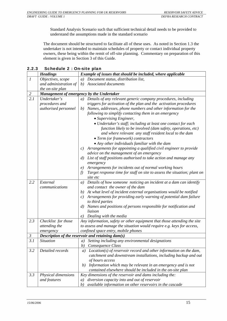
15/06/2006 15
Standard Analysis Scenario such that sufficient technical detail needs to be provided to understand the assumptions made in the standard scenario
The document should be structured to facilitate all of these uses. As noted in Section 1.3 the undertaker is not intended to maintain schedules of property or contact individual property owners, these being within the remit of off-site planning. Commentary on preparation of this element is given in Section 3 of this Guide.
2.2.3 Schedule 2 : On-site plan Headings Example of issues that should be included, where applicable 1 Objectives, scope
and administration of the on-site plan
a) Document status, distribution list, b) Associated documents
2 Management of emergency by the Undertaker 2.1 Undertaker’s
procedures and authorised personnel
a) Details of any relevant generic company procedures, including triggers for activation of the plan and the activation procedures
b) Names, addresses, phone numbers and other information for the following to simplify contacting them in an emergency
• Supervising Engineer, • Undertaker’s staff; including at least one contact for each
function likely to be involved (dam safety, operations, etc) and where relevant any staff resident local to the dam
• Term (or framework) contractors • Any other individuals familiar with the dam
c) Arrangements for appointing a qualified civil engineer to provide advice on the management of an emergency
d) List of staff positions authorised to take action and manage any emergency
e) Arrangements for incidents out of normal working hours f) Target response time for staff on site to assess the situation; plant on
site etc 2.2 External
communications a) Details of how someone noticing an incident at a dam can identify
and contact the owner of the dam b) At what level of incident external organisations would be notified c) Arrangements for providing early warning of potential dam failure
to third parties d) Names and positions of persons responsible for notification and
liaison e) Dealing with the media
2.3 Checklist for those attending the emergency
Any information, safety or other equipment that those attending the site to assess and manage the situation would require e.g. keys for access, confined space entry, mobile phones
3 Description of the reservoir and retaining dam(s) 3.1 Situation a) Setting including any environmental designations
b) Consequence Class 3.2 Detailed records a) Location(s) of reservoir record and other information on the dam,
catchment and downstream installations, including backup and out of hours access
b) Information which may be relevant in an emergency and is not contained elsewhere should be included in the on-site plan
3.3 Physical dimensions and features
Key dimensions of the reservoir and dams including the: a) diversion capacity into and out of reservoir b) available information on other reservoirs in the cascade

ENGINEERING GUIDE TO EMERGENCY PLANNING FOR UK RESERVOIRS RESERVOIR SAFETY ADVICE DRAFT GUIDE : VOLUME 1 DEFRA RESEARCH CONTRACT
15/06/2006 16
Headings Example of issues that should be included, where applicable 3.4 Other facilities
relevant to on-site operations
Other installations on, or adjacent to, the undertaker’s land which may be relevant in an emergency, for example because of potential hazard and/or consequential damage
3.5 Access to reservoir a) Key holders? b) Alternative routes to dam and other features that may be necessary
in an emergency c) Weight/width limits on site and adjacent roads? d) Vehicle size constraints? e) Roads that may be cut-off by flooding?
3.6 Communications at reservoir site
a) Which mobile telephones networks work at the site b) Nearest landline telephones
3.7 Welfare facilities Welfare facilities on, or adjacent to the site 3.8 Normal operation Details of normal operation, including
a) responsibilities for different functions, such as dam safety management, maintenance, operation
b) frequency of surveillance (this affects how quickly any structural problem would be detected, and the time available to prevent failure)
4 Actions by undertaker on site 4.1 Situation assessment a) Details of who would carry out the on-site assessment
b) Health, safety and environmental issues in implementing the on-site plan
4.2 Undertaker’s resources relevant to on-site activities
a) Equipment on site b) Communications equipment c) Other resources available (labour, materials, plant including
pumping equipment), with the location and (24 hour) contact details 4.3 Reservoir drawdown a) Curves of drawdown of the reservoir vs. time for full opening of the
bottom outlet for a range of inflow conditions b) Alternative means of lowering, if the structural problem relates to
the outlet to be used for emergency drawdown c) Consequent risks that may be created e.g. rapid drawdown slope
failure of the dam and reservoir d) Maximum releases from the reservoir for no downstream property
damage 4.4 Other measures a) Other measures that could be taken to avert failure
b) Risk assessment of carrying out candidate work c) This risk assessment may indicate that it would be appropriate to
add other sections to this on-site plan. 4.5 Off-site impacts of
site activities a) On third parties e.g. flooding, environmental impact b) On the Undertaker’s operations
4.6 Assistance from external organisations with on-site measures
e.g. Police in relation to the use of public highways for access and/or plant, closing roads/footpaths and providing diversions; Local Authority EPO in procuring additional pumps; etc
5 Measures at other installations 5.1 Interaction with
other reservoirs in the cascade (where present)
a) Communication between different undertakers b) Precautionary actions that could be taken if there is a serious
incident at an upstream reservoir c) Actions to mitigate the effect of the dambreak flood wave, e.g.
lowering of a downstream reservoir to absorb the flood wave 5.2 Measures at other
installations a) Any other means of temporarily diverting inflows, away from the
reservoir. b) Actions to mitigate the effect of the dambreak flood wave

ENGINEERING GUIDE TO EMERGENCY PLANNING FOR UK RESERVOIRS RESERVOIR SAFETY ADVICE DRAFT GUIDE : VOLUME 1 DEFRA RESEARCH CONTRACT
15/06/2006 17
Headings Example of issues that should be included, where applicable 6 Maintenance of the On-site plan 6.1 Training of staff Include the arrangements for training staff in the duties they are
expected to perform, and the time period to refresher courses 6.2 Periodic testing of
equipment a) Would normally include full opening of the bottom outlet at least
annually b) Need for advance warning of testing and potential environmental
impact c) Record keeping of testing
6.3 Exercising a) Level, type and frequency of exercise e.g. desk top, full scale field, component testing
b) Staff e.g. Undertaker only or include 3rd parties 6.4 Review and updating
of the plan a) Frequency of checking and updating contacts b) Date of next full review,
Commentary is given in Section 4 of this Guide.
2.2.4 Schedule 3 : External Interfaces plan
Headings Example of issues that should be included, where applicable 1 Objectives, scope
and administration of the Plan
a) Document status, distribution list b) Associated documents
2 Notification by undertaker of serious incident at a reservoir 2.1 Information to be
provided to Local Resilience Forum
Content and format of information that would be provided to the Local Resilience Forum in the event of a serious incident including a) status of warning e.g. early warning, likely failure or dam failed b) anticipated failure mode c) action being taken to avert failure d) estimated probability of failure (High/ Medium/Low) and indication
of the likely time to failure 2.2 Available relevant
documents List of available documents that may be of assistance in managing incident including: a) inundation analysis –date, revision number, distribution list b) on-site plan c) protocols regarding statutory duties for the Undertaker’s business
which may be affected by the dam burst e.g. dealing with burst water mains and sewers
3 Management of serious incident by Undertaker 3.1 Undertaker’s
procedures and authorised personnel
a) Reservoir site and Undertaker details b) Emergency control centre c) Contact details for people authorised to manage emergencies;
including base office address, office, mobile and home phone numbers
d) Arrangements for defining and notifying the level of serious incident 3.2 Communications How media contacts will be managed, including contact details of Press
Officer(s) 3.3 Undertaker’s
Resources relevant to off-site activities
a) Representation during an incident at the Local Resilience Forum Control room
b) Resources committed to activities e.g. responsibilities as Category 2 responder
c) Resources which could be made available to assist Category 1 responders with off-site activities relating to dam failure
d) In some situations, where agreed with the police and LRF, it may be

ENGINEERING GUIDE TO EMERGENCY PLANNING FOR UK RESERVOIRS RESERVOIR SAFETY ADVICE DRAFT GUIDE : VOLUME 1 DEFRA RESEARCH CONTRACT
15/06/2006 18
Headings Example of issues that should be included, where applicable appropriate for the Undertaker to provide warning to the population at risk immediately downstream of the dam
4 Maintenance of the External Interface plan 4.1 Training of staff Include arrangements for training staff in the duties they are expected to
perform, where appropriate co-ordinating this with other organisations 4.2 Exercising a) Level, type and frequency of exercise e.g. desk top, full scale field;
component testing b) Staff e.g. Undertaker only or include 3rd parties
4.3 Review and updating of the plan
a) Frequency of checking and updating contacts b) Date of next full review
Commentary is given in Section 5 of this Guide.
2.3 Technical Specification under Section 12A (2)(b) of the Reservoirs Act 1975 (as amended by the Water Act 2003) Section 12A (2)(b) of the Reservoirs Act 1975 (as amended by the Water Act 2003) makes provision for the specification of “methods of technical or other analysis”. This relates to the impact assessment element of a reservoir flood plan, with the specification given here together with commentary on the basis of the Specification. Depending on the level of risk involved, dam-break analyses may vary considerably in scale and the amount of detail. It is however crucial that the principal output from all such analyses is presented in a consistent manner. The following Technical Specification is therefore to be followed in all cases.
2.3.1 Standard analysis a) The hydraulic analysis will cover the Standard Analysis Scenario as defined in the
Engineering Guide to Emergency Planning, or as otherwise accepted by the Environment Agency. The Undertaker may identify further scenarios for which they wish to present output. Output should in all cases be presented consistently with that for the Standard Analysis.
It should be noted that the Specification is intended to cover a limited number of key issues for the impact assessment only, being the minimum necessary to define a permissioning regime (HSE, 2000, 2003) and to facilitate enforcement of this regime. The requirements vary with the level of analysis carried out. It is also noted that the only mandatory requirement is the use of the Standard Analysis Scenario and the content of the output, but that other assumptions including ground data and breach discharge rely on the user's judgement with guidance given in this document. b) Table of peak breach outflows for different failure scenarios and flow paths, to identify
which would give the highest peak discharge into each of the flow paths into which the reservoir could escape
c) The analysis shall be carried out by subdividing the downstream valley into Zones, the boundaries of which shall be • no further apart than 20 minute travel time for the peak flood discharge except in areas
where population and properties at risk are sparse when travel times of up to two hours would be acceptable.

ENGINEERING GUIDE TO EMERGENCY PLANNING FOR UK RESERVOIRS RESERVOIR SAFETY ADVICE DRAFT GUIDE : VOLUME 1 DEFRA RESEARCH CONTRACT
15/06/2006 19
• at significant changes in topography, transport infrastructure and other hydraulic controls on the dam break flood
• at the upstream and downstream limits of settlements, if not otherwise represented. d) Details and key dimensions in tabular form of transportation embankments across the
critical flow path which could affect the flow down the flow route, including approximate dimensions of bridges and culvert openings
The dimensions of transportation embankments are intended to be approximate (typically ±25% accuracy), to assist in the judgement as to whether the embankment would breach during the dam break flood. They would therefore be obtained from measurements made/ estimated during a walk over survey in the field, and inspection of aerial photographs, rather than needing to contact the owners of the infrastructure. It is good practice to include photographs of embankments (and associated cross drainage structures) which are likely to have a significant effect on flow conditions down the valley. e) The following output shall be provided at Zone boundaries, for each failure scenario:
• Ordnance Survey grid references (in seven digit format suitable for GIS use) • distance from the reservoir (measured along the modelled flow path) • the time to the onset and peak of flooding; time zero may be any convenient value but
the assumed times of onset of failure and peak flow of the most downstream reservoir must be quoted on the same timescale.
• on the cross section forming the zone boundary the maximum discharge, maximum average velocity and maximum depth of flooding relative to ground level in the base of the valley (channel invert and defence levels would not be available without site specific ground survey), normally quoted to a precision of 0.1m
• for the length of valley represented by the zone: the total population at risk; the likely loss of life, the typical level of property damage (inundation, partial structural or structural destruction) and value of third party property damage in pounds
It is suggested that data such as the arrival time and the maximum flood depth are generally best presented in tabular form. Nevertheless the user can choose to add these to the map, where it does not affect the clarity of the specified information. f) Figures shall be provided showing:
• Flood hydrographs at zone boundaries • how the peak flow varies with distance down the valley, both for each scenario
analysed and for the 1% and 0.1% annual probability floods with no dam failure • a longitudinal section down the valley, showing the level of the base of the valley and
the peak dam break water level The longitudinal section provides a useful check on both the effect of transportation embankments and the quality of the ground model. Attention is drawn to the comments in Section 3.2.3.5 on transportation embankment across the flow path and Section B.5 on the ground elevation data. g) A table shall be provided showing, for each failure scenario, the estimated total
population at risk; the likely loss of life; third party property damage and consequence class, in the event of dam failure together with a build up of these estimates
h) In addition damage parameters of both velocity and depth shall be provided in tabular form at selected Key Points to include • Key transportation infrastructure: Airports, Railways, A-Roads and above, canals • Locations specified by others under Clause 14 of the Defra specification

ENGINEERING GUIDE TO EMERGENCY PLANNING FOR UK RESERVOIRS RESERVOIR SAFETY ADVICE DRAFT GUIDE : VOLUME 1 DEFRA RESEARCH CONTRACT
15/06/2006 20
i) The output from the inundation analysis shall be in an electronic form in a standard GIS format based on 1:10000 scale mapping, with hard copy maps within the impact assessment plan as follows (each clearly labelled with flow path name and failure scenario) • Model layout plan showing the location of all sections and structures included in the
hydraulic model • Flood risk map, including extent of flooding and properties flooded where velocity is
less than or greater than 2m/s • Inundation plan showing extent of flooding and suitable for photocopying in black and
white and at a map scale no smaller than 1: 10,000 The output shall be suitable for overlaying onto Ordnance Survey maps to allow others to • assess the impacts on other installations, such as high pressure gas mains, electricity
substations etc • compare and combine the results with that received from other sources.
It is recommended that maps are normally presented at no greater than A3 size paper, to facilitate use in an emergency. Attention is drawn to the comments in Section 3.2.3.5 on how to show the extent of flooding upstream of transportation embankment across the flow path j) the flood plan submission shall be accompanied by an electronic copy of the hydraulic
model and data used in building the model Hydraulic modelling involves large quantities of electronic data, both in terms of the model and various run input and output. A systematic approach should be adopted to both documenting and auditing the quality of all aspects of the data involved in hydraulic modelling. This clause is to ensure the data is available for record purposes.
2.3.2 Rapid method of analysis This shall be as for the Standard Analysis, except that Items ‘f’, ‘h’ and ‘i’ are not required.
2.3.3 GIS Format suitable for use by Category 1 Respondents All digital geographical data submitted as part of an emergency plan shall conform to the appropriate Environment Agency standards, as disseminated publicly. The information to be supplied will be as set out in the Agency GIS Specification, but shall include
• the extent of inundation • base data • ASCI download of cross sections including geographical location

ENGINEERING GUIDE TO EMERGENCY PLANNING FOR UK RESERVOIRS RESERVOIR SAFETY ADVICE DRAFT GUIDE : VOLUME 1 DEFRA RESEARCH CONTRACT
15/06/2006 21
3 SCHEDULE 1 : IMPACT ASSESSMENT Summary of this Section
This section of the Guide provides guidance on the preparation of Element I of a Reservoir flood plan, as defined in Schedule 1 of the Specification accompanying any Direction by the Secretary of State under Section 12A of the Reservoirs Act 1975 (as amended by the Water Act 2003). This Section of the Guide should be read in conjunction with the following: a) Appendix B - detailed issues regarding hydraulic modelling b) Appendix E - completed example of a rapid impact assessment for Element I c) Appendix F - completed example of a standard impact assessment for Element I d) Technical Specification for GIS output (a separate document to be mounted on the
Environment Agency website)
The section is structured following the eight headings in Schedule 1, with the specification text in italics, followed by guidance on satisfying the requirements of the Specification.
3.1 Objectives, scope and administration of impact assessment
Headings Example of issues that should be included, where applicable 1 Objectives, scope and
administration of the impact assessment
a) Reservoirs and dams covered by impact assessment b) Document status, distribution list, c) Other impact assessments covering these dams
3.1.1 Objectives
In the preparation and maintenance of the inundation analysis and consequence assessment (termed “impact assessment”) the assessment should provide sufficient information for the various uses noted in the commentary after Schedule 1 (Section 2.2.2). In particular a dam break impact assessment is intended to a) Identify the area likely to be inundated in the event of a dam failure, and thus allow those
responsible for emergency planning and response to make informed decisions when planning for possible future events, and when dealing with actual events.
b) Provide data which can be used by others in assessing the risk to other infrastructure c) Quantify the likely impact on third parties, such that the dams retaining the reservoir can be
assigned a Consequence Class, as defined in the Interim Guide to Quantitative Risk Assessment for UK Reservoirs (Brown & Gosden, 2004)
As noted in the Preface, it is expected that technology will move forward during the life of this Guide. It is reasonable to expect that new and improved software, more powerful computers, and better geographic data will become available. It is therefore anticipated that some software and methodologies which are currently acceptable, may not be considered suitable for new studies in the future. It will be open to Defra to provide guidance on any change in minimum standards for new analysis, in consultation with the Environment Agency and other stakeholders. In relation to updating any existing analysis the as low as reasonably practicable (ALARP) approach should be adopted, through assessing the likely reduction of risk that would be achieved by updating the analysis, and whether this is proportionate to the cost of undertaking that analysis. As noted in Section 1.3 the undertaker is not intended to maintain schedules of property or contact individual property owners.

ENGINEERING GUIDE TO EMERGENCY PLANNING FOR UK RESERVOIRS RESERVOIR SAFETY ADVICE DRAFT GUIDE : VOLUME 1 DEFRA RESEARCH CONTRACT
15/06/2006 22
3.1.2 Scope
The Impact assessment should
a) tabulate all the reservoirs and dams to which the document applies b) provide a schematic plan of the dam(s) and flow paths c) identify whether any reservoir is retained by more than one dam, such that the reservoir
could breach into more than one valley
3.1.3 Administration This section should provide details, preferably in tabular form of
a) the status and distribution of the document. b) what measures are required to keep the information secure, following the circular letter
from Defra dated 29th March 2005
3.2 Scenarios modelled in impact assessment
Headings Example of issues that should be included, where applicable
2 Scenarios modelled in analysis E.g. dam failure, gate/valve opening
3.2.1 General The technical specification requires that analysis includes a "standard scenario", for a number of reasons including
• to achieve a repeatable, conservative estimate of the extent and impact of dam failure • that Category 1 responders can understand the wide range of possible scenarios,
and the severity/ assumptions in the "standard scenario". • to simplify enforcement of the reservoir flood plans, so that the enforcement authority
do not have to agree the scenario to be adopted on each individual dam. This section first describes the range of credible dam failure scenarios that could occur, and then goes on to describe the standard scenario. It then comments on the implications for the extent of evacuation and when additional scenarios may be included in an impact assessment, concluding with the information that should be included in the plan.
3.2.2 Uncertainties in extent of inundation due to dam failure
3.2.2.1 Release of water from reservoir The possible scenarios for release of water from a reservoir are noted in Appendix B. In addition to uncertainties over the release scenario and location of the failure along the dam axis, there is also uncertainty over the time that failure takes to occur. The latter has a significant effect on the peak flow released into the downstream channel.
3.2.2.2 Effect of downstream infrastructure embankments Transportation embankments across the flood plain may act as secondary dams. Although where small and breached in an early part of the flood this may be insignificant, in some situations this may be significant in terms of the extent of dambreak inundation and risk to people. This is illustrated in the example in Figure C.3 in Appendix F; where the figure shows the water levels in many of the upper reaches is governed by transportation embankments.

ENGINEERING GUIDE TO EMERGENCY PLANNING FOR UK RESERVOIRS RESERVOIR SAFETY ADVICE DRAFT GUIDE : VOLUME 1 DEFRA RESEARCH CONTRACT
15/06/2006 23
The actual behaviour of transportation embankments while the dam break flood wave is passing will be complex, will vary with time and may include failure by overtopping, piping along the structure interface or scour at the downstream side of the structure. Depending on the timing of any such failure relative to the passage of the dam break flood, breach of such an embankment may cause a secondary flood wave which could in itself have significant potential for loss of life and damage. In terms of hydraulic analysis Table 3.1 summarises the possible scenarios for a transportation embankment across the flow path. Where an embankment breaches this may lead to higher flows downstream, which in turn makes it more likely that transportation embankments further downstream would themselves fail. Thus overall there is a significant number of possible scenarios, depending both on the behaviour of individual embankments and the likelihood that the failure of any embankment influences the probability of failure of any other. Assessment of the risk to those in the potential inundation area is further complicated by the location of the population at risk: • where upstream of an embankment then the risk to life is maximised if the embankment is
intact as this maximises any overtopping depth (although acknowledging that the fatality rate would be low because of reduced velocities);
• where downstream of an embankment then the risk to life is maximised if the embankment breaches at an early stage in the dam break flood because this would lead to higher downstream flows.
Table 3.1 : Possible scenarios for effect of transportation embankments on extent of inundation
Transportation embankment Location of effect Intact Breached by dam break flood Upstream Increased inundation
upstream (water level backed up as determined by the size of culvert opening, the degree and timing of blockage and the height of embankment) but reduced velocity
Two stages of behaviour a) Increasing inundation, limited to the overtopping depth
necessary to breach the embankment b) After the breach, the upstream water levels will be
governed by the breach dimensions; where the breach is wide control may change to the valley cross section and slope
Downstream Peak flows attenuated by storage upstream of transportation embankment
Potentially three phases a) Dam break wave from breach of the embankment b) Water depths and velocities governed by the breach
dimensions c) Once the breach has developed to a sufficient width
there will be no attenuation of the peak flow, with the water depth and peak velocity governed by the valley section and bed slope
3.2.2.3 Incremental damage caused by dam failure
For failure during extreme floods it is likely there would have been significant damage even if the dam does not fail; particularly for small reservoirs on large catchments where a dam failure may lead to only a few centimetres increase in depth of flooding. In this situation the consequences of dam failure are only those in excess of the “no-failure damages” i.e. the incremental damage caused by the dam failure. However, for internal erosion failure modes not at a time of fluvial flooding, the whole damage would be due to dam failure.

ENGINEERING GUIDE TO EMERGENCY PLANNING FOR UK RESERVOIRS RESERVOIR SAFETY ADVICE DRAFT GUIDE : VOLUME 1 DEFRA RESEARCH CONTRACT
15/06/2006 24
In defining the standard scenario there is a choice between a) the total damage, for simplicity and noting it is a conservative estimate b) analysis of both failure and no-failure scenarios, and identification of the incremental
damage due to dam failure.
3.2.3 Standard dam breach analysis scenarios
3.2.3.1 Background One approach would be to specify the standard scenario as being the “most probable” failure mode (this is the “extendability” approach adopted in the nuclear industry, as defined in Appendix A.1.2). However, this will vary between dams and has significant uncertainty in reliably estimating both the most likely dam failure modes and the associated annual probabilities of failure. It has therefore been decided that Standard Analysis Scenario for dam break should comprise
a) the rainy day scenario as described below, reflecting a likely maximum dam break flood from a full reservoir.
b) dam break discharges (but not routed down the valley) for other credible scenarios, to allow an assessment of how the flood extent may vary from those estimated in the Standard Analysis Scenarios.
c) total consequences (no deductions of damages that would occur from fluvial flooding if the dam did not fail)
3.2.3.2 Definition
The “Emergency Planning Dam Failure Standard Analysis Scenarios” shown in Table 3.2 should be adopted as the minimum analysis. Additional assumptions in regard to the valley and the effect of infrastructure embankments are shown in Table 3.3. The Sunny day analysis scenario is optional, being of increased value in defining the range of possible breach discharges where the peak dam breach flow is less than say 50% of the rainy day breach flow. Thus it would normally only apply where a reservoir flood plan covers a cascade of reservoirs. For long dams, including non-impounding dams and service reservoirs, there may be a significant number of alternative locations of possible failure along the dam. Following on from the precept that reservoir flood plans are intended to protect the public the Standard Analysis Scenario calls for the failure location to be that which has the worst impact on the public, the “Critical flow path” (see definitions in Section 7.2). If the application of the Standard Analysis Scenario is considered to be inappropriate in a particular case, the undertaker (and their independent qualified civil engineer) shall propose for the consent of the Environment Agency the scenario to be analysed in advance of the preparation of the Impact Assessment. This proposal shall include reasoned justification for the proposed change. In the event of uncertainty remaining, the undertaker shall submit their best interpretation of the agreed scenario but may take advantage of their right to submit alternative scenarios as part of their overall flood plan.
3.2.3.3 Commentary – breach assumptions The 10,000 year flood as the incoming flood at dam failure is selected in preference to the PMF because of the general desire to move away from PMF towards a T-year approach (Recommendation 5 in KBR, 2002).

ENGINEERING GUIDE TO EMERGENCY PLANNING FOR UK RESERVOIRS RESERVOIR SAFETY ADVICE DRAFT GUIDE : VOLUME 1 DEFRA RESEARCH CONTRACT
15/06/2006 25
It is recognised that the dam failure Standard Analysis Scenario may not reflect a likely failure mode at a particular dam, for example for impounding reservoirs where the spillway is designed to pass the 10,000 year or PMF flood the Standard Analysis Scenario may be an unlikely failure mode (unless the spillway was blocked prior to the flood). However, it is defined, for the purposes of emergency planning, to provide a consistent approach to planning for dam failure. The Rainy Day Standard Analysis Scenario should generally prove to be conservative, particularly in the valley close to the dam. It is noted that the Rainy day Standard Analysis Scenario neglects runoff from the catchment downstream of the dam; for simplicity because of the wide range of possible severity and spatial extent of storms. It is thus implicit that the extent of inundation and consequences in the Standard Analysis Scenario arise largely from the dam failure, such that the issues of incremental discharge and damages relative to the “no dam failure” scenario are not included. If there is significant flood runoff from the downstream catchment and the timing of the peak flow of this coincides with dam failure then the peak flood flow in the lower part of the valley could increase above the rainy day scenario. This is illustrated in Figure 3.1. For this reason the technical specification requires that an indicative estimate be made of the potential run-off from the catchment(s) downstream of the dam, and that this be included in the reservoir flood plan in both tabular and graphical form on a long section in a format similar to that of Figure 3.1. In the event that a dam is in danger of imminent failure during an extreme regional flood event and the timing of the peaks is likely to coincide then an approach similar to that of Figure 3.1 may be adopted to estimate the potential peak flow, and thus assist with extrapolation of the extent of inundation.
3.2.3.4 Commentary – flood detention reservoirs For flood detention reservoirs it is noted that the most likely scenario in which the dam could fail with a full reservoir is in (or immediately following) an extreme flood event when the downstream valley is already flooded. In this scenario failure
• could be caused by blockage of a spillway by trees/ floating debris; or internal erosion failure triggered by the unusually high reservoir level.
• would be a particular risk to the emergency services • would create a flood wave where the dam temporarily ponds water to a greater depth
than natural flooding The Standard Analysis Scenario is therefore considered reasonable.
3.2.3.5 Commentary - effect of infrastructure embankments Where there are transportation embankments of a height which is significant in relation to the depth of the dam break flood wave this can have a significant effect on flow conditions down the valley, as discussed in Section 3.2.2.2. The recommended approach is given in Table 3.3 and Figure 3.2. The amount of blockage that could occur in a flood will depend on the size of the opening and the presence and size of debris. This would need to be assessed on a site by site basis; the values in Table 3.4 could be used as a starting point. The maps and longitudinal section required under the technical specification may either show separately the extent of flooding in the hydraulic model and the temporary greater extent of upstream inundation prior to breach of the embankment, or show whichever is greater. In a few circumstances it may be appropriate to model a transportation embankment as a downstream dam, failing in cascade. The additional effort is only likely to be proportionate where the breach flow from the transportation embankment could exceed the peak flow from the subject dam.

ENGINEERING GUIDE TO EMERGENCY PLANNING FOR UK RESERVOIRS RESERVOIR SAFETY ADVICE DRAFT GUIDE : VOLUME 1 DEFRA RESEARCH CONTRACT
15/06/2006 26
3.2.3.6 Downstream limit of modelling
The inundation analysis should extend to a point defined under Item 9 in Table 3.2. It is accepted that the downstream boundary for hydraulic modelling has to be defined before the extent of dam break flooding is available, such that there may be a degree of iteration required. In practice a suitable downstream limit would normally be the confluence with another significant watercourse, or similar step increment in catchment area. Where the modelled flow significantly exceeds the criteria for the downstream boundary then the model should be extended. The rapid method may be used to assist in defining a suitable end point for the model. There remains a risk to the population downstream of the boundary determined as above, but this would generally be significantly smaller than the risk upstream of the boundary and is likely to be limited to inundation rather than structural damage or loss of life.
Figure 3.1: Illustration of possible effect of downstream inflows on peak flood flow
0
100
200
300
400
500
600
700
0 5 10 15 20
Distance downstream of dam (km)
Peak
flow
(m3 /s
)
Dam break Rainy day (no downstreaminflows)Dam break Sunny day
Runoff from catchment downstream ofdam 100 yearRunoff from catchment downstream ofdam 1000 yearCombined Rainy day+ 1,000 year
Steady state base flow prioir to damfailure
Flood damage due to fluvial flood (no dam failure)
Incremental flood damage due to dam failure
Step increase in fluvial flood at confluence with another tributary

ENGINEERING GUIDE TO EMERGENCY PLANNING FOR UK RESERVOIRS RESERVOIR SAFETY ADVICE DRAFT GUIDE : VOLUME 1 DEFRA RESEARCH CONTRACT
15/06/2006 27
Table 3.2 : Definition of Standard Dam Breach Analysis Scenarios
Item Requirements for impounding reservoirs Rainy day Sunny day (Note 4)
Requirements for non-impounding and service reservoirs
Further guidance in
Section 1 Number of dams
involved and critical flow path
For reservoirs in cascade all dams on the Flow Path (Note 1) fail, triggered by the failure of the most upstream dam. Where there are alternative flow paths (as defined in the Defra Specification) into the same watercourse then the analysis shall be for the critical flow path (defined in Section 7.2)
Lowest dam on cascade only
As for impounding reservoirs, rainy day
2 Failure mode Failure in a manner to achieve the peak breach discharge defined elsewhere in the Guide, and such that the whole contents of the reservoir are released. Thus the failure mode assumes failure at the time of the peak inflow into the reservoir (for all types of inflow, including breach discharge from an upstream dam).
As rainy day, except that tailwater should be for dry weather flow.
All compartments fail in a manner which maximises the peak breach discharge. Internal dividing walls are to be disregarded, such that the breach hydrograph is based on the volume of all compartments
3.3
3 Timing of failure at individual dam
Commencement of the breach at the time of peak inflow to the reservoir (in a cascade this will lead to consecutive failure, starting from the upstream reservoir and progressing downstream).
As rainy day Where there is more than one reservoir on the flow path, then second and subsequent reservoirs fail as for impounding reservoirs
4 Inflows into reservoir(s)
10,000 year extreme rainfall event; input both as the inflow to the upper reservoir, and as inflows in each upstream sub-catchment. Also maximum possible indirect inflows
Normal baseflow as Note 3
Maximum possible indirect inflows 3.2.3.3
5 Initial reservoir level and reservoir volume in hydraulic model (in all reservoirs)
Case A: Where the spillway is vulnerable to more than 10% blockage in a major flood (Table 3.4) the reservoir is fully surcharged with an initial reservoir level, prior to routing the flood inflows, determined as follows:
a) if there is a crest wall which could structurally withstand a flood surcharge: at the top of the wall
b) if there is no wall, or it could not withstand the surcharge: at the dam crest c) if there is another dam retaining the reservoir with a lower crest/ flood wall, then the lowest top
level for all of the dams determined as ‘a’ or ‘b’ Case B: In all other cases the initial reservoir level is spilling a normal baseflow as Note 3
The initial reservoir level is spilling a normal baseflow as Note 3, subject to achieving mathematical stability
Full to soffit of roof, or to top of embankment or crest wall (if continuous).
6 Steady state flow prior to the dam failure
The initial flow should be sufficient for model stability throughout the cascade and should not generally exceed the peak of a 1000 year flood at any point on the flow path. Where this is not feasible, the initial flow should not exceed 10% of the maximum breach discharge.
The initial flow should not exceed 10% of the maximum breach discharge.
The steady state initial flow should not exceed 10% of the maximum breach discharge at that point
7 Controlled outflows from reservoir
All adjustable level and flow control equipment (e.g. spillway gates, bottom outlets, valves, penstocks) remain closed throughout the event regardless of their normal positions or settings, and that automatic systems (e.g. fuse gates) fail to operate.
Equipment functions as intended
As for impounding reservoirs, rainy day
8 Inflow from tributaries downstream of reservoir (Note 2)
Neglect inflows on basis that “Dam failure Standard Analysis Scenario” is generally conservative As Rainy day As for impounding reservoirs, rainy day
9 Downstream boundary for impact assessment (Note 5)
Where the • predicted extent of flooding is less than the 100 year fluvial flood extent and/or • where the peak flow of the attenuated dam-break flood is less than that of the 100 year flood
As Rainy day The point at which velocity and depth are below the threshold at which the population is included in the Population at Risk
3.2.3.6
10 Base Population at risk
Average on 24hour/365day basis, being the product of normal building occupancy and occupancy factor. No allowance for prior evacuation
As Rainy day As for impounding reservoirs, rainy day
11 Ground model along flow path
a) IfSAR data (see Table B.3 of this Guide) or better. Channel may be neglected except where its capacity significantly exceeds the 1% annual probability flood
b) Other aspects as given in Table 3.3
As Rainy day As for impounding reservoirs, rainy day 3.2.3.5
Notes 1. Small reservoirs, defined as having a capacity of less than 5% of the total volume of the other reservoirs on the flow path, may be neglected. 2. The inflow from side tributaries downstream of the reservoir will depend on the spatial extent of rainfall (e.g. Dales & Reed, 1989), if a rainy day flood; or would be normal river flows if sunny day failure. Historically this was often
neglected because it could not be modelled in DAMBRK. 3. Normal base flow should be taken as the 50 percentile daily flow for that catchment (see Section 4.4.3.4 of this Guide) 4. Sunny day failure is optional, and may be of value for emergency planning where peak dam breach flow is less than 50% of the rainy day breach flow

ENGINEERING GUIDE TO EMERGENCY PLANNING FOR UK RESERVOIRS RESERVOIR SAFETY ADVICE DRAFT GUIDE : VOLUME 1 DEFRA RESEARCH CONTRACT
15/06/2006 2:23 PM 28 P:\Environment\0022203 Defra research 2002-06\206 Task F Eng Guide to emergancy planning\Guide 04 Draft for Public consultation\2006-06-12 Final\Vol 1 Eng Guide Emgy Plan R04.09r.doc
Table 3.3 : Physical factors affecting attenuation of flood wave down valley
Issue Remarks Recommended standard approach 1 Infrastructure
embankments crossing the inundation area
a) Although gaps are included in embankments across the watercourse in IfSAR elevation data, these are inserted to achieve hydraulic continuity for high level fluvial flood mapping, and may not reflect the geometry which would result if the embankment breached as a result of dam failure.
b) Where canal embankments are breached this can lead to additional inflows, and may warrant modelling of additional scenarios
c) In urban areas large diameter drains and transport tunnels may act as sinks to flow; although the associated storage capacity is only likely to be relevant to Non-impounding and Service Reservoirs
a) Embankments running parallel to the direction of flow and/or intruding on but not fully crossing the flood plain should be represented in cross sections but not modelled as limiting the flooded area
b) Embankments running across the direction of flow should be assessed in steps as shown on Figure 3.2. Guidance on breach dimensions are given in Section 3.4.4.
c) Neglect large diameter drains and transport tunnels in routing the flood
2 Dense urban development across base of valley
Buildings across the floodplain will obstruct the flow, with the issues being similar to transportation embankments, in terms of whether the buildings are destroyed by the time of the peak of the dam break flood, or whether they remain and constrict the flow. Where they remain structurally intact but plate glass windows and cladding are removed by the force of the flood significant flow may pass through the structure.
Follow the same approach as for transportation embankments, i.e. where a) likely to be destroyed by the
time of the peak flow use increased roughness possibly with raised bed level to model flattened debris
b) building(s) remain intact either insert as constrictions in the cross section, or model as continuous obstruction with gaps to model streets etc.
3 Roughness coefficients
The roughness will vary in time and space: a) across a section (e.g. in-bank channel,
across flood plain) b) between urban and rural areas; open and
forested areas c) during a flood; for example, as vegetation
and/or property is damaged or removed
See main text (Section 3.4.5)
4 Sediment and debris
a) Debris is likely to block most bridges and culverts
b) bed level can change during the flood due to deposition (or erosion) of sediment and debris e.g. Carpart et al.1998 and Carpart, 2000, and Graham, 1998 report a 5m to 10m change in bed levels during dam break flooding
a) Allowed for at structure in considering blockage of culverts through transportation embankments
b) Normally neglect effect on valley cross section
5 Debris flows/ lahars
Mobilisation of large quantities of debris by floods can lead to debris flows (sometimes called lahars) which behave differently to normal flood flows
No evidence for occurrence in UK conditions

ENGINEERING GUIDE TO EMERGENCY PLANNING FOR UK RESERVOIRS RESERVOIR SAFETY ADVICE DRAFT GUIDE : VOLUME 1 DEFRA RESEARCH CONTRACT
15/06/2006 2:23 PM 29 P:\Environment\0022203 Defra research 2002-06\206 Task F Eng Guide to emergancy planning\Guide 04 Draft for Public consultation\2006-06-12 Final\Vol 1 Eng Guide Emgy Plan R04.09r.doc
Figure 3.2 : Flow chart to model transportation embankment across flow path Hydraulic modelling
1. Site visit with non-contact distance measuring equipment, to determine approximate size of culverts/ bridge openings, and
embankment height
2. Assess risk of blockage of bridge/ culvert; determine % blocked to be used in dam break modelling
3. Run dam break analysis assuming all structures block as Step 2, but embankments do not breach
4. Does the embankment and any opening attenuate peak flow significantly (say downstream peak flow < 80% upstream peak), or cause ponding upstream (upstream water depth > 120% of downstream water depth)?
No
Yes
5. Is it reasonable to assume the structure will breach under dam break conditions?
No
Yes
6. Define proportions of breach through embankment
Yes 7. Any additional embankments across flow path?No
8. Re-run hydraulic analysis with embankments breached as Step 6, or intact and blocked as Step 3
Hydraulic mapping
9 Dam break flood levels taken as the higher of a) flood levels from 8,b) for those embankments which breach, the peak water level prior to breach (often
sufficient to simplify to a horizontal line at the top of the embankment plus overtopping depth, projected upstream)
Inundation maps produced from intersection of these flood levels with DTM
Maximum velocity and hydrodynamic properties as output from Step 8 (do not use those from 9'b' when assessing damage)

ENGINEERING GUIDE TO EMERGENCY PLANNING FOR UK RESERVOIRS RESERVOIR SAFETY ADVICE DRAFT GUIDE : VOLUME 1 DEFRA RESEARCH CONTRACT
15/06/2006 2:23 PM 30 P:\Environment\0022203 Defra research 2002-06\206 Task F Eng Guide to emergancy planning\Guide 04 Draft for Public consultation\2006-06-12 Final\Vol 1 Eng Guide Emgy Plan R04.09r.doc
Table 3.4 : Preliminary values of blockage of structures in dam break scenario
Size of opening (lesser/minimum
dimension)
% blockage of culvert/ bridge in transportation embankment, due to sediment, trees, building debris etc
% blockage of spillway weir/ chute, where trees are present either around the reservoir
or on any incoming watercourse, within 1km of the reservoir.
>10m 10% Nil 5-10m 50% 10% 2-5m 80% 25% <2m 100% 50%
3.2.4 Area to be evacuated in event of imminent dam failure
The decision as to the areas to be evacuated and sequence of evacuation (e.g. whether vulnerable elements of the population are evacuated when a preliminary warning is given) are likely to be made by the by the Police Gold or Silver Commander (coordinating the response from members of the Local Resilience Forum), or in the event of a quick response the Police Operational Commander. In all occasions decisions will take into account information provided by the Undertaker and his advisors. The inundation maps provided in the Inundation analysis will normally show the outer limit of inundation. This extends beyond the limits setting the boundary in which “population at risk” is determined, which is where both the water depth exceeds 0.5m and the product of velocity and depth is greater than 0.5m2/s. However, attention is drawn to the following issues which may lead to the extent of inundation and risk to people varying from that shown on the maps a) the overall duration for the reservoir to fail may vary from that predicted, which is likely to
have a significant effect on the peak flow as the dam fails, and thus peak flows down the valley
b) infrastructure embankments across the valley will generally act as significant constraints to propagation of the dam break flood wave downstream; particularly where any existing openings are blocked by debris carried by the dam break flood and the embankments are high (the comments in 3.2.2 apply). The effect of these embankments is also likely to vary with time as openings become blocked and where the embankment breaches, leading to time varied effects additional to that of (superimposed on) the dam break hydrograph
c) the ground model used in the hydraulic analysis is obtain from remote sensing from aircraft; filtered using automatic algorithms to remove trees and buildings; in areas which are thickly wooded and there are steep slopes there is particular scope for errors (see Section B.5.1)
d) Where the magnitude of the dam break flood wave is such that the flow spills out of a clearly defined valley, the flow path(s) are likely to be complex, being affected by development on the flood plain, erodibility of surface materials and other factors
The extent of inundation for the Rainy day Standard Analysis Scenario is a generally conservative scenario assuming the worst combination of dams in the cascade fail. In the event that imminent failure involves other scenarios the extent of inundation would vary with the breach discharge but also dependent on inflows from downstream tributaries. The extent of inundation for the Sunny day Standard Analysis Scenario would generally be a lower bound for the extent of inundation if the dam failed when the reservoir was full (level with the spillway). In the event that the dam failed during emergency drawdown of the reservoir, with the reservoir partially drawn down the extent of inundation would depend on the breach discharge, which would depend on the geometry and the rate of development of the breach.

ENGINEERING GUIDE TO EMERGENCY PLANNING FOR UK RESERVOIRS RESERVOIR SAFETY ADVICE DRAFT GUIDE : VOLUME 1 DEFRA RESEARCH CONTRACT
15/06/2006 2:23 PM 31 P:\Environment\0022203 Defra research 2002-06\206 Task F Eng Guide to emergancy planning\Guide 04 Draft for Public consultation\2006-06-12 Final\Vol 1 Eng Guide Emgy Plan R04.09r.doc
3.2.5 Additional scenarios The Undertaker may analyse other failure scenarios or carry out sensitivity studies, to inform either his own safety management or the uncertainties in the extent of potential dam break inundation. These may be included in the impact assessment at the discretion of the Undertaker. Whether this is limited to noting the differences in breach discharge, or whether separate inundation maps are produced is also at the discretion of the Undertaker. Floods due to the failure of hydraulic control structures may also require more detailed modelling because they could lead to sustained high discharges within the range which present a risk to bridges and other hydraulic structures, and to waterfront property, without necessarily overtopping embankments or flooding large areas. Where additional scenarios or sensitivity studies are carried out, the Impact assessment should clearly differentiate between the results for the Standard Analysis Scenario, and the results of sensitivity studies. It is recommended that the Standard Analysis results are included for comparison on plans of alternative flood scenarios.
3.2.6 Information provided in reservoir specific assessment The plan for individual reservoirs should provide justification for the scenarios analysed, including commentary on how the assumptions in Tables 3.2 to 3.3 have been implemented Where the reservoir is part of a cascade, the plan for each reservoir in the cascade should include the estimated dam breach discharge for all possible combinations of failure of dams within the cascade, to ensure that the flow paths and combination of dam failures are correctly identified.
3.3 Dam Break Discharges and critical flow paths Headings Example of issues that should be included, where
applicable 3 Dam break discharges and critical
flow paths Dam break flood for all scenarios considered, as well as critical flow paths adopted for analysis
3.3.1 Introduction
Three basic approaches may be used for the assessment of dam-breach hydrographs:
a) assumptions about breach geometry and the time taken for the breach to develop; b) formulae based on the analysis of historic events relating discharge to parameters such
as dam height and storage capacity. c) numerical modelling of physical processes occurring during the breach requiring
information about the erodibility of fill materials etc. It is noted that the breach outflow will vary depending on the mode of failure and materials forming the dam; for example a clay core dam with sand fill shoulders being overtopped is likely to lead to much faster breach development than a foundation failure. The most realistic estimate is considered likely to be using approach ‘b’. However, this approach does not produce the complete flood hydrograph required for realistic assessment of the potential impacts in the downstream valley.

ENGINEERING GUIDE TO EMERGENCY PLANNING FOR UK RESERVOIRS RESERVOIR SAFETY ADVICE DRAFT GUIDE : VOLUME 1 DEFRA RESEARCH CONTRACT
15/06/2006 2:23 PM 32 P:\Environment\0022203 Defra research 2002-06\206 Task F Eng Guide to emergancy planning\Guide 04 Draft for Public consultation\2006-06-12 Final\Vol 1 Eng Guide Emgy Plan R04.09r.doc
Alternative ‘c’ would be the ideal solution in theory, and software is available to apply it, but there is insufficient understanding of erosion processes to reliably predict breach hydrographs (and the erodibility data required is generally not available for an intact dam). Most available hydraulic modelling software has provision to incorporate a geometric definition of breaches, and to calculate flow through a breach as it develops, taking account of reservoir storage and concurrent flood flows, thus producing the necessary downstream hydrograph, but with limitations on the credibility of the peak flow. Such software also allows backwater effects on breach discharges to be modelled, as might be relevant where there are significant hydraulic constraints immediately downstream of the breached dam.
3.3.2 Embankment dams It is recommended that the breach discharge hydrograph used in the Standard Analysis Scenario is defined such that the peak breach discharge is as Froehlich (1995a): QP = 0.607 V0.295 H1.24 Where QP = peak breach discharge (m3/s) V = reservoir capacity (m3) H = height of peak reservoir level
above base of dam (m)
The guidance given on pages 48 and 49 of CIRIA Report C542 (2000) can be adopted to estimate the time to peak and time base of the hydrograph with: a) the time to peak taken as 120 times dam height b) the duration of the flood wave is taken as a triangular hydrograph with a volume equal to
the reservoir volume, subject to reducing Tp and Te in accordance with the CIRIA Report to ensure that the hydrograph volume is the same as the reservoir volume.
This approach would provide a usable outflow hydrograph for a sunny day scenario for a single dam. A dam failure associated with significant reservoir inflows, including those arising from the failure of upstream dams, requires a more dynamic approach, however, and it is therefore recommended that a breach formation process be developed for each dam in a cascade individually by varying breach width, side slope and development time by a process of trial and error until the peak discharge approximates the Froehlich value. If this is done in the same program as will be used for the flood routing, the hydrograph time step (and the model results reporting time step) will need to be set to a short enough value to allow the peak flow to be clearly identified.
3.3.3 Concrete Dams For this Guide the relation in Section 5.2.2 of CIRIA REPORT C542 is adopted, as being the latest published information, whereby the peak discharge is:
QP = 0.9R 0.28 L H 1.5 Where QP = peak breach discharge (m3/s) R = ratio between breach area and total dam face area L = length of the dam across the valley (m) H = height of peak reservoir level above base of dam (m)

ENGINEERING GUIDE TO EMERGENCY PLANNING FOR UK RESERVOIRS RESERVOIR SAFETY ADVICE DRAFT GUIDE : VOLUME 1 DEFRA RESEARCH CONTRACT
15/06/2006 2:23 PM 33 P:\Environment\0022203 Defra research 2002-06\206 Task F Eng Guide to emergancy planning\Guide 04 Draft for Public consultation\2006-06-12 Final\Vol 1 Eng Guide Emgy Plan R04.09r.doc
L and R are both measured at the reservoir level for which breaching is considered. In gravity and buttress dams the breach area would normally be an integral number of blocks in the dam, selected from consideration of potential failure modes. It is recommended that the iterative approach to developing an outflow hydrograph be adopted as is proposed for embankment dams.
3.3.4 Service Reservoirs There are a number of potential breach mechanisms of service reservoirs, which vary significantly in the rate of failure and thus potential peak discharge. The mechanism which is likely to lead to the fastest failure is a foundation stability failure. For this mechanism it is suggested to:
• adopt the concrete dam breach equation but with the “gravity dam” parameter values • constrain the breach width to a single panel (between movement joints) • consider failure at each distinct alternative location around the perimeter of the
reservoir.
This approach can however produce unfeasibly high discharges, given the limited storage capacity of service reservoirs, and the absence of significant inflows. Following the CIRIA Report C542 methodology for developing an outflow hydrograph to its limit may still leave a hydrograph volume greater than the storage in the reservoir. In such circumstances, it is appropriate to reduce the peak discharge. It is not necessary to consider the further development of breach parameters, as service reservoirs should never be subject to significant inflows during a failure event. The nature of service reservoir locations, on the tops of hills and/or in the middle of urban areas, means that numerous flood routes are possible and that these frequently do not follow obvious valleys.
3.3.5 Cascades It is suggested that as a first approximation the breach geometry for the second and subsequent dams in a cascade is defined on the basis of a breach hydrograph estimated:
a) using the height of the subject dam and the cumulative volumes of the subject reservoir and all upstream reservoirs, in conjunction with the equation appropriate to the dam type
b) the volume of the most upstream reservoir (i.e. the first in the cascade) should be as the initial reservoir level in the Standard Analysis Scenario (Table 3.2)
c) the volume of the second and subsequent reservoirs should be fully surcharged to the top of the crest wall (or dam crest) i.e. Case A in Table 3.2.
In some cases the magnitude of the inflow from failure of the dams further upstream may be greater than the nominal outflow from the dam at the bottom of the cascade. This is not a problem for the Standard Analysis, as the 1-D unsteady modelling will allow for attenuation in the reservoir and thus correct for this effect. For the rapid method this situation should be allowed for as described in the Interim Guide to Quantitative Risk Assessment (2004) and supplements. Application of the definition of “Critical Flow path” given in Section 7.2 should normally make it straightforward to identify the sequence of dam failures to be considered in a cascade.

ENGINEERING GUIDE TO EMERGENCY PLANNING FOR UK RESERVOIRS RESERVOIR SAFETY ADVICE DRAFT GUIDE : VOLUME 1 DEFRA RESEARCH CONTRACT
15/06/2006 2:23 PM 34 P:\Environment\0022203 Defra research 2002-06\206 Task F Eng Guide to emergancy planning\Guide 04 Draft for Public consultation\2006-06-12 Final\Vol 1 Eng Guide Emgy Plan R04.09r.doc
3.3.6 Information provided in reservoir specific assessment This should provide the following
• breach discharge for all dams covered by plan • the critical flow path which was modelled • the dimensions of the breach, and development time, as used in the model
3.4 Methodology for Hydraulic Routing Headings Example of issues that should be included, where applicable 4 Methodology
for hydraulic routing
Description of methodology and assumptions in the analysis of routing of the dam break flood down valley downstream of the dam; including a) Level of analysis (Standard, Rapid) b) Software and ground data used c) Treatment of transportation embankments
3.4.1 General
Dam-break modelling for the purpose of emergency planning comprises three principal elements:
a) Assessment of the potential discharge arising from a failure scenario b) Routing the resulting estimated flood down the valley c) Assessment of the impact of the flood
The following sections provide guidance on the generic model characteristics required for a consistent approach to dam-break analysis, specifically ‘b’ above, additional to the requirements in the definition of “Standard Analysis Scenario”. It is possible to address this process using a single integrated analysis package or a number of individual tools: there is no one “correct” approach to the process of analysis. Item ‘a’ above is covered in the previous section, whilst Item ‘c’ is covered in Section 3.5 onwards. The estimation of floods is not covered, as this is adequately covered in standard texts. It is appropriate to use the FEH rainfall-runoff approach for the estimation of catchment floods unless better estimates already exist. The event duration used should be appropriate for the reservoir catchment(s). Guidance on modelling is given in Appendix B.
3.4.2 Level of analysis Reference is made to two levels of analysis: a “Rapid” screening level appropriate for low consequence dams and the “Standard” level of analysis for high consequence dams. Where the consequence class of the dam is unknown then an initial screening can be carried out using the Rapid method, followed where appropriate by the Standard analysis. The recommended methodology for rapid impact assessment is given in the Interim Guide to Quantitative Risk Assessment for UK Reservoirs and is not repeated here, although a completed example of such an analysis is given in Appendix E. In terms of the Standard Analysis a description of the various issues relating to hydraulic modelling is given below and in Appendix B. This includes program types together with a list of software.

ENGINEERING GUIDE TO EMERGENCY PLANNING FOR UK RESERVOIRS RESERVOIR SAFETY ADVICE DRAFT GUIDE : VOLUME 1 DEFRA RESEARCH CONTRACT
15/06/2006 2:23 PM 35 P:\Environment\0022203 Defra research 2002-06\206 Task F Eng Guide to emergancy planning\Guide 04 Draft for Public consultation\2006-06-12 Final\Vol 1 Eng Guide Emgy Plan R04.09r.doc
It is anticipated that for most UK impounding reservoirs some form of 1-D modelling would be appropriate. In this situation although water depth varies across the section, a single “average” value of velocity applies at each section.
3.4.3 Data Requirements Whichever set of tools is adopted for carrying out a dam-break analysis, certain core data items will be required for a “Standard” inundation analysis. The data are summarised in Tables 3.5 and 3.6. The quality of the hydraulic analysis and the subsequent inundation mapping however depends crucially on the geographical data used and it is essential to understand the implications of the choice of elevation data source, as the cheapest option may not ultimately yield the cheapest study. The data requirements in Table 3.5 are the standard information which would be expected to be available for any reservoir falling under the requirements of the Reservoirs Act 1975. Much of the data listed in Table 3.6 can be obtained from the Environment Agency (some through a pan government agreement on use of data). This would be free to undertakers, where necessary to carry out their legal obligations.
Table 3.5 : Data required for modelling breach discharge from reservoir
Data Reason needed
1 Reservoir water level vs. surface area or volume (area data preferred)
Calculation of discharges from reservoir
2 Elevation or longitudinal section along dam axis
To confirm size and shape of feasible breaches.
3 Cross section across dam, from upstream to downstream toe including (where available): details of fill materials; dam crest construction; and type/ levels of foundation cut-off
To confirm likely type of failure, bottom level of assumed breach, overtopping level, top water level, plus whether top of concrete cut-off would influence breach characteristics
4 Spillway level(s), normal maximum water level (if different), other critical levels (e.g. crest levels of other dams forming the reservoir)
To assist in confirming reservoir operation in no-failure case and initial conditions prior to failure.
5 Type and dimensions of spillway(s); discharge rating curves if available; details of emergency spillways (e.g. fuse gates, fuseplug, grassed spillway)
To assist in confirming reservoir operation in no-failure case and initial conditions prior to failure.
6 Flood inflow and outflow from reservoir design and/or safety assessments
For comparison with modelled flows
Notes 1. Data required for consequence assessment is given in Table 3.7.

ENGINEERING GUIDE TO EMERGENCY PLANNING FOR UK RESERVOIRS RESERVOIR SAFETY ADVICE DRAFT GUIDE : VOLUME 1 DEFRA RESEARCH CONTRACT
15/06/2006 2:23 PM 36 P:\Environment\0022203 Defra research 2002-06\206 Task F Eng Guide to emergancy planning\Guide 04 Draft for Public consultation\2006-06-12 Final\Vol 1 Eng Guide Emgy Plan R04.09r.doc
Table 3.6 : Other data required for hydraulic analysis
Data Owner of data
Status Reason needed
1 1:10,000 scale maps in electronic format (raster)
Ordnance Survey
Essential Geographic detail
2 Digital elevation data/ ground model – see Table B.4 It is recommended that IfSAR is used as the minimum standard
Various Essential Define valley shape, flood extents and flood depths
3 Field survey of channel sections, structures on/ across flow path
Environment Agency
Optional Improve accuracy of flood modelling, although noting channel capacity is normally insignificant in relation to magnitude of dambreak flows.
4 Key dimensions of transportation embankments across dam break flow route, including bridge/ culvert openings (see Appendix B.5.2 for comment on modelling)
Various Essential1 Define whether the dam break flood will back up and overtop the embankment, leading to a secondary breach, or whether the dam break can be passed through the bridge/culvert with no overtopping of the transportation embankment.
5 Dimensions and form of construction of buildings comprising dense urban development across base of flow path, which could obstruct flow
Various Where available
Define the extent to which the dam break flood will back up due to the constriction across the flow path
6 Orthorectified, or other, aerial photography
Various Optional Assists in assessment of valley roughness; clarification of land use
7 Agency 100 and 1000 year flood mapping and detailed flood mapping (Section 105), if different, or equivalent.
Environment Agency
Where available
Assessment of no-failure flood risk and downstream limit of flood risk modelling
8 Previous river modelling (if available)
Environment Agency
Where available
Useful starting point, especially where the channel capacity is likely to be significant. However, it can be difficult to determine adequately the location of model sections on the ground.
Notes 1. It is anticipated this will normally be obtained by the engineering company preparing the impact assessment, as described in Appendix B.5.2 of this Guide (where not available from ‘3’)

ENGINEERING GUIDE TO EMERGENCY PLANNING FOR UK RESERVOIRS RESERVOIR SAFETY ADVICE DRAFT GUIDE : VOLUME 1 DEFRA RESEARCH CONTRACT
15/06/2006 2:23 PM 37 P:\Environment\0022203 Defra research 2002-06\206 Task F Eng Guide to emergancy planning\Guide 04 Draft for Public consultation\2006-06-12 Final\Vol 1 Eng Guide Emgy Plan R04.09r.doc
3.4.4 Transportation embankments across flow path The recommended methodology is given in Table 3.3 and Figure 3.2. In relation to the breach dimensions it is noted that the breach may be significantly wider than a dam breach where the transportation embankment breaches early in a flood, because of the prolonged flow through the breach (Wahl, 1998 includes one lateral erosion model). The suggested approach is to use the prediction equation suggested by Froehlich (1995b) namely Bw = 15 Ko V 0.32 H 0.19 Where Bw - average breach width, in metres Ko - 1.4 for overtopping failure mode; 0.9 otherwise V - volume of water in Mm3 (it is recommended that the overall dam break volume is used) H - height of final breach , in metres Z - sideslope, taken as 1.4H:1V for overtopping failure mode; 0.9H:1V otherwise
3.4.5 Roughness coefficients There is no uniform guidance on the selection of Manning’s ‘n’ for dam-break analysis. Work reported by Sellin and Van Beesten (2004) shows that the channel ‘n’ varies significantly on a seasonal basis, as expected. There are also indications that roughness drops as a consequence of the demolition of obstructions to flow, and thus changes during the dam-break flood. The magnitude of dam-break flows is such that the depth of flow in the valley is closer to channel proportions than it is to flood plain flow in most cases. Users of ‘n’ could therefore expect to use values in the region of 0.05 for the, reasonably unobstructed, centre of the valley and 0.1 or higher for areas of shallower flow or greater degree of obstruction. The Conveyance Estimation System (CES, Defra/EA, 2004), though currently untested in this respect, should be able to extend to model this situation and may be able to take account of changes in roughness during an event. Standard application of CES will provide upper and lower bound results by default.
3.4.6 Information provided in reservoir specific assessment This should provide a description of the methodology, key assumptions and features of the modelling, including the following
• level of analysis • data and software used, preferably in tabular form, both for hydraulic analysis and for
flood mapping • Manning’s ‘n’ • downstream limit of model, including justification • comment on whether reasonable to neglect the channel capacity (as implied by use of
IfSAR ground model), and any existing flood defences • structure dimensions and loss coefficients (where modelled separately from that given
in the base IfSAR data)

ENGINEERING GUIDE TO EMERGENCY PLANNING FOR UK RESERVOIRS RESERVOIR SAFETY ADVICE DRAFT GUIDE : VOLUME 1 DEFRA RESEARCH CONTRACT
15/06/2006 2:23 PM 38 P:\Environment\0022203 Defra research 2002-06\206 Task F Eng Guide to emergancy planning\Guide 04 Draft for Public consultation\2006-06-12 Final\Vol 1 Eng Guide Emgy Plan R04.09r.doc
3.5 Consequence assessment Headings Example of issues that should be included, where applicable 5 Consequence
assessment Description of the methodology and assumptions in estimating the a) number of buildings in the inundation area, and the area and type of
non-residential property, and the degree of damage b) number of people (population) at risk, with the broad location e.g.
discrete settlements, isolated locations, campsites, recreational facilities, those on transportation routes etc suitable for use by the Local Resilience Forum for the assessment of risk
c) likely loss of life (the base case is with no warning) d) third party property damage
3.5.1 Introduction
This section discusses how to estimate the following:
• population at risk • likely loss of life • damage to third party property • consequence class of the dam (see Figure 3.3)
The process is summarised on Figure 3.4, with commentary on the methodology is given in the Interim Guide to Quantitative Risk Assessment for UK reservoir (Brown & Gosden, 2004), and its supplements. The comments in Section 3.2 regarding the downstream boundary should be noted. Commentary on the presentation of the output from the hydraulic modelling for flood risk mapping is given in Appendix B. It should be noted that the estimates of population at risk, likely loss of life and third party damage are a) for the purposes of assigning an appropriate consequence class and facilitating risk
assessment by the Local Resilience Forum, and not for the purposes of detailed planning of evacuation or other possible off-site activities.
b) not intended to be accurate estimates but are an indicative average, with a “normal approach” specified to achieve consistency between the impact assessments rather than necessarily indicating any particular accuracy of the estimate. In particular the population at risk will vary with time of day, and day of the week.
c) indicative based on a desk study with no detailed field verification. In particular the number and types of property may vary from those indicated where there has been new development and/ or demolition of redundant buildings
The Local Resilience Forum have access to the inundation maps and can make their own assessment of potential consequential problems, such as risk to major services, other hazardous installations and storage of hazardous substances.
3.5.2 Level of analysis and data requirements Table 3.7 shows the level of detail required for Rapid and Standard Analysis. The decision on whether to enhance the level of detail in the estimate should be determined taking into account issues such as the benefits to risk management and emergency planning.

ENGINEERING GUIDE TO EMERGENCY PLANNING FOR UK RESERVOIRS RESERVOIR SAFETY ADVICE DRAFT GUIDE : VOLUME 1 DEFRA RESEARCH CONTRACT
15/06/2006 2:23 PM 39 P:\Environment\0022203 Defra research 2002-06\206 Task F Eng Guide to emergancy planning\Guide 04 Draft for Public consultation\2006-06-12 Final\Vol 1 Eng Guide Emgy Plan R04.09r.doc
0.001
0.01
0.1
1
10
100
10000.001 0.01 0.1 1 10 100 1000
Likely loss of life
Third
par
ty d
irect
floo
d da
mag
e du
e to
dam
failu
re £
M
A2
B
C
CD
A1
A1
B
A2
Figure 3.3 : Overall Consequence class (as Sheet 11.2 of Interim Guide to QRA, ICE, 2004)
Figure 3.4 : Flow chart for estimation of consequences of dam failure
Identify properties in inundation area, subdivided into R and NR.
For each property determine how many floors affected by flood wave
Estimate occupancy of each building, and sum to obtain Population at risk (PAR) in each zone down the flow
path
Determine level of damage (structural or inundation)
using the peak discharge divided by flooded with estimate the fatality rate (Figure 9.1 in Interim Guide to QRA)
for each zone
Estimate cost of damage, by multiplying property number or area by cost of damage for appropriate level
of damage
Estimate the likely loss of life (LLOL) in each zone, and sum to obtain the
overall LLOL
Assign consequence class based on likely loss of life and third party property damage

ENGINEERING GUIDE TO EMERGENCY PLANNING FOR UK RESERVOIRS RESERVOIR SAFETY ADVICE DRAFT GUIDE : VOLUME 1 DEFRA RESEARCH CONTRACT
15/06/2006 2:23 PM 40 P:\Environment\0022203 Defra research 2002-06\206 Task F Eng Guide to emergancy planning\Guide 04 Draft for Public consultation\2006-06-12 Final\Vol 1 Eng Guide Emgy Plan R04.09r.doc
There are several alternatives sources for the data that is required for a consequence estimate and some of these are summarised in Table 3.8. This data is often GIS based, and data format and availability is likely to develop relatively rapidly in the future. Some of this data is available free on the internet, some should be available from the Environment Agency (as for modelling data in Table 3.6) whilst some would only be available commercially. It is noted that the rapid method is likely to underestimate the number of properties (and thus the consequences of dam failure) as the following cannot be deduced from the 1:25,000 scale map: a) semi detached and terraced houses (and blocks of flats) cannot be differentiated from
detached houses b) small to medium non-residential properties in an area of housing cannot be differentiated
from residential properties c) the number of floors in non-residential properties Although a site visit should allow corrections to a desk based assessment for the above, where the number of properties is large this is likely to become impractical. The rapid method is therefore better suited to low to medium consequence dams, and for preliminary comparative screening of higher consequence dams. In terms of other damages these may be added where considered appropriate by the undertaker, and can include
a) Emergency services costs of response and recovery relating to the dam break (these amounted to 10.4% of property damage costs in the 2000 floods)
b) Environment Agency costs of response and emergency repairs to watercourses c) Restore transportation and utility infrastructure d) Direct damage to agricultural land e) Traffic disruption f) Temporary accommodation for those affected by flooding g) Intangibles
3.5.3 Information provided in site specific assessment
The methodology and key assumptions used in assessing the following shall be given in the flood plan
• Number of residential properties, • Number, building area and type of non-residential properties • Base Population at risk (PAR) and Likely loss of life (LLOL) • Cost of Third party property damage, and date of assessment • Consequence class (as defined in Sheet 11.2 of the Interim Guide to QRA of UK
reservoirs) This shall include a description of any difficulties encountered, and additional assumptions made in the analysis. It is anticipated that identification of, and information on, sites of environmental and cultural importance that could be affected by a dam failure would be given in any off-site plan. Attenuation is drawn to the government website www.magic.gov.uk which collates the various statutory designations.

ENGINEERING GUIDE TO EMERGENCY PLANNING FOR UK RESERVOIRS RESERVOIR SAFETY ADVICE DRAFT GUIDE : VOLUME 1 DEFRA RESEARCH CONTRACT
15/06/2006 2:23 PM 41 P:\Environment\0022203 Defra research 2002-06\206 Task F Eng Guide to emergancy planning\Guide 04 Draft for Public consultation\2006-06-12 Final\Vol 1 Eng Guide Emgy Plan R04.09r.doc
Table 3.7 : Level of detail in estimating likely consequences of dam failure
Property database Population at risk in property
Number and area of buildings affected1
Subdivision of property type Subdivision for valuation of damage
Number of floors2
Categorisation of level of property damage
Rapid Estimated from 1:25,000 scale OS map (thus only major NR properties identified)
Single digit property code for each of residential (R) and non-residential (NR)
Regional average Two for residential, one for non-residential
Inundation or Structural; based on representative value for that zone
Single values of the following for each of R and NR a) occupant area/
person (NR) b) number occupants/
house (R) c) occupancy factor
(%/ time) Standard Taken from a GIS dataset, otherwise as Rapid
As Rapid As Rapid Judgment based on available information on property
As Rapid As Rapid
Other options for enhanced estimate4 Break down NR to one of
a) four bulk classes, in ODPM rateable value statistics
b) property type into at least 2 digit Multicoloured manual (MCM) code, or equivalent (Middlesex, 2005)
R broken down by property type into at least 2 digit MCM code, or equivalent
Broken down to a) Local
authority b) Other
postcode level
a) Subdivide each zone into levels of damage (up to 3 levels as Binnie, 1991), based on either
- adjacent model cross section - position relative to outer
edges of inundation4 b) Inundation damage related to
depth of inundation, using existing methodology for economics of flood alleviation schemes
Break down NR on similar basis to property type4

ENGINEERING GUIDE TO EMERGENCY PLANNING FOR UK RESERVOIRS RESERVOIR SAFETY ADVICE DRAFT GUIDE : VOLUME 1 DEFRA RESEARCH CONTRACT
15/06/2006 2:23 PM 42 P:\Environment\0022203 Defra research 2002-06\206 Task F Eng Guide to emergancy planning\Guide 04 Draft for Public consultation\2006-06-12 Final\Vol 1 Eng Guide Emgy Plan R04.09r.doc
Notes to Table 3.7 1. All levels require a site visit to check the validity of the property database; this is particularly important for the rapid method 2. Where structural destruction should allow for the destruction of all floors in the building 3. Likely loss of life should be single value for each zone, as curves in Figure 9.1 of the Interim Guide to QRA is based on observed fatality rates
averaged over zones 4. This is most useful where there is a limited number of large non-residential properties in the inundated area. This approach has been adopted in the
worked example in Appendix F.
Table 3.8 : Alternative sources of data required to quantify consequences of dam failure, and possible sources
Data Possible alternative sources Owner of data
Applicable to Remarks
NR
R (Num) Num Area
1 Property number and gross area1
a) Direct measurement from Ordnance Survey 1: 10,000 scale map
Ordnance Survey √ √ √
a) this is the suggested method for Rapid analysis b) Where a dense industrial area, then for the rapid method
the area could be estimated as that of the whole industrial area x the % occupied by buildings
b) Polygons on “Master map”
Ordnance Survey √ √ √
c) Address Point property location data
Post Office √ √ X
d) Customer database Water company √ √ X
e) National property
database Environment Agency √ √2 √2
Includes rateable value of each NR property; may omit non-rateable property such as places of worship. Floor area may be estimated by dividing the rateable value by the rateable value/m2 for that local authority, obtained from 3b
2 Population at risk2 National census √ X
Building occupancy Architects data e.g. Pickard,
2002 Publisher √ √

ENGINEERING GUIDE TO EMERGENCY PLANNING FOR UK RESERVOIRS RESERVOIR SAFETY ADVICE DRAFT GUIDE : VOLUME 1 DEFRA RESEARCH CONTRACT
15/06/2006 2:23 PM 43 P:\Environment\0022203 Defra research 2002-06\206 Task F Eng Guide to emergancy planning\Guide 04 Draft for Public consultation\2006-06-12 Final\Vol 1 Eng Guide Emgy Plan R04.09r.doc
Data Possible alternative sources Owner of data
Applicable to Remarks
NR
R (Num) Num Area
3 Property valuation2 Inundation
damage a) Multicoloured manual
(MCM), Middlesex University, 2005
Publisher
√ √
a) Data is presented in several levels of detail, from single digit for average of all property, to three digit for property type and social class
b) Provides data on value of contents of both R and NR property
b) Commercial and Industrial Floorspace and Rateable Value Statistics
ODPM
X √
This may be used to estimate: • Average floor area for NRP in the inundation area, by
dividing the total area in a local authority area by the number of NRP in that area
• Market value for building element of NRP, by dividing the rateable value by yield
Total destruction
c) Market value for residential property. www.landregistry.gov.uk
Land Registry √ X
This data is available from the Land Registry at levels from national down to 4 digit postcode, at timescales down to quarterly. There are also various websites on which recent sale prices are available, for a payment.
Notes R- Residential (domestic); NR – Non-residential 1. Some of the information in Table 3.6, such as a ground model may also be needed, to assign threshold levels to property 2. Suggested values are given in the Interim Guide to Quantitative risk assessment for UK reservoirs (Brown & Gosden, 2004)

ENGINEERING GUIDE TO EMERGENCY PLANNING FOR UK RESERVOIRS RESERVOIR SAFETY ADVICE DRAFT GUIDE : VOLUME 1 DEFRA RESEARCH CONTRACT
15/06/2006 2:23 PM 44 P:\Environment\0022203 Defra research 2002-06\206 Task F Eng Guide to emergancy planning\Guide 04 Draft for Public consultation\2006-06-12 Final\Vol 1 Eng Guide Emgy Plan R04.09r.doc
3.6 Results of impact assessment Headings Example of issues that should be included, where applicable 6 Results of impact
assessment Present the results of the impact assessment in the format required by the technical specification, for each flow path into which the reservoir could breach
The results should be presented in the form of tables and maps showing the results of both the hydraulic analysis and consequence assessment, as required by the technical specification. Attention is drawn to the commentary under Section 17 of the Defra Specification. Where major utility services are identified in the field which are likely to be vulnerable to severing in a dam break situation, these can be included in the plan if wished. It is noted that the Local Resilience Forum has the power to obtain this information from Category 2 responders.
3.7 Impact on Infrastructure Headings Example of issues that should be included, where applicable 7 Impact on
infrastructure a) Velocity and depth at locations of key road/rail links and any other infrastructure the loss of which would cause major disruption b) Commentary on whether the existing infrastructure could attenuate the flood wave (sufficient to flag options to Category 1 responders)
3.7.1 Severing of transportation links
The Impact assessment should provide a schedule of key infrastructure, as defined in the Technical Specification, with the estimated velocity and depth at bridges or culverts.
3.7.2 Possible use of infrastructure for attenuating flood wave The Impact assessment should comment on where existing infrastructure, or downstream dams, could be used to reduce the peak dam break flow. Comment in the impact assessment should be limited to the identification of any possible options, with assessment of the practicality and other aspects left to any off-site plan.
3.8 Maintenance of the Impact assessment Headings Example of issues that should be included, where applicable 8 Maintenance of the
impact assessment The period of time to the next review of the impact assessment and updating as necessary. May include several levels of review and update e.g. a) downstream infrastructure and population at risk b) developments in methods of analysis
The general comments in Appendix A.1.3 on the maintenance of emergency plans apply. The Impact assessment should be reviewed (and updated or modified where appropriate) as follows: a) check that no change in development in, or across, flow path(s) which may affect dam break
flow or consequences of failure at the frequency indicated in Table 3.9 b) full review no less frequently than the Section 10 Inspection of the most upstream reservoir. A full review should include a review of the methodology used in the original analysis, and an assessment of whether a partial or full update is likely to significantly improve the value of the

ENGINEERING GUIDE TO EMERGENCY PLANNING FOR UK RESERVOIRS RESERVOIR SAFETY ADVICE DRAFT GUIDE : VOLUME 1 DEFRA RESEARCH CONTRACT
15/06/2006 2:23 PM 45 P:\Environment\0022203 Defra research 2002-06\206 Task F Eng Guide to emergancy planning\Guide 04 Draft for Public consultation\2006-06-12 Final\Vol 1 Eng Guide Emgy Plan R04.09r.doc
plan in terms of risk reduction at the reservoir. The update may often be limited to the consequences of failure, with no change in the hydraulic analysis.
Table 3.9 : Indicative frequency of maintenance of impact assessment
Form of Maintenance
Type1
Frequency for Overall Consequence Category
Application
A1 A2 B Review & Update
Development in or across flow path(s) which may affect dam break flow or consequences of failure
Annual 2 years 5 years Every reservoir

ENGINEERING GUIDE TO EMERGENCY PLANNING FOR UK RESERVOIRS RESERVOIR SAFETY ADVICE DRAFT GUIDE : VOLUME 1 DEFRA RESEARCH CONTRACT
15/06/2006 2:23 PM 46 P:\Environment\0022203 Defra research 2002-06\206 Task F Eng Guide to emergancy planning\Guide 04 Draft for Public consultation\2006-06-12 Final\Vol 1 Eng Guide Emgy Plan R04.09r.doc
4 SCHEDULE 2 : ON-SITE PLAN Summary of this Section
This section of the Guide provides guidance on the preparation of Element II of a Reservoir flood plan, as defined in Schedule 2 of the Specification accompanying any Direction by the Secretary of State under Section 12A of the Reservoirs Act 1975 (as amended by the Water Act 2003). It should be read in conjunction with
a) Appendices G, H : Includes completed examples of Element II b) Appendix C : Prompt sheets for assessment of possible mitigation measures to avert
failure at a dam c) Environment Agency protocols for releases from reservoirs, a separate document to be
put on the Agency website
The section is presented in the form of the relevant headings in the Schedules in the Specification in italics, followed by guidance on satisfying the requirements of the Specification.
Data Requirements
Data that would normally be required for the preparation of the On-site plan includes that summarised in Table 4.1. In addition site specific information on issues such as access, facilities, resources etc would be required, following the headings in Schedule 2.
Table 4.1 : Data required by Undertaker for preparation of an on-site plan
Data Reason needed 1 Any generic information common to all high hazard installations
owned by the Undertaker • emergency management plan(s) or processes, following
the checklist in Tables 4.2 and 4.3 • resources for physical works
To avoid unnecessary work/ repetition in preparing the On-site plan
2 Data on the characteristics of the reservoir, retaining dams and appurtenant works
• Geometry and construction of dam(s) • Plan and schedule of valves
For inclusion in the On-site plan
3 Reservoir level vs. area or volume curves 4 Capacity of Draw off works over a range of reservoir levels
For calculation of how quickly the reservoir can be lowered
5 Typical values of Inflows over a year** Notes ** Where not available, then may be estimated using data on internet for nearest Environment Agency gauging station
Detail of Plan
Two examples of an on-site plan are provided a) a plan for a cascade of reservoirs all owned by the same Undertaker, an Undertaker of a
significant number of reservoirs, employing technical staff to manage them b) a plan for a single reservoir owned by an Undertaker with no technical staff The two examples are prepared to illustrate the range of content and style of on-site plan that might occur, whilst still being responsive to the specified requirements for contents. The detail given in the plan should be determined by the Undertaker, comply with the minimum specified

ENGINEERING GUIDE TO EMERGENCY PLANNING FOR UK RESERVOIRS RESERVOIR SAFETY ADVICE DRAFT GUIDE : VOLUME 1 DEFRA RESEARCH CONTRACT
15/06/2006 2:23 PM 47 P:\Environment\0022203 Defra research 2002-06\206 Task F Eng Guide to emergancy planning\Guide 04 Draft for Public consultation\2006-06-12 Final\Vol 1 Eng Guide Emgy Plan R04.09r.doc
requirements and be determined by evaluating whether additional detail will add value in terms of avoiding or mitigating the risk of failure of the dam in the event of an emergency.
4.1 Objectives, scope and administration of the on-site plan
In the preparation of the on-site plan the following assumptions should normally be made
a) The on-site plan will be for use by those unfamiliar with the reservoir e.g. someone standing in for the Supervising Engineer who is not available, an Inspecting Engineer, Emergency Services, Environment Agency, or any Category 1 responder
b) The Reservoir Record is available c) Any existing drawings of the dam(s) are available
Headings Example of issues that should be included, where
applicable 1 Objectives, scope and
administration of the on-site plan
a) Document status, distribution list, b) Associated documents
4.1.1 Objectives
Preparation and maintenance of an on-site plan is intended to
a) prevent failure of the dams covered by the plan in the event of an emergency b) in the event that failure cannot be averted, the On-site plan is intended to identify actions
which would delay failure to allow off-site actions to be taken, and also reduce the breach discharge, both of which are intended to reduce the loss of life.
It should therefore be suitable to
• Brief employees of the Undertaker (and subcontractors) who are unfamiliar with the dam, such that they can effectively contribute to measures to avert failure in the event of an emergency
• Set out the processes to be followed, and other information required to manage any emergency which could lead to dam failure
4.1.2 Scope
The on-site plan should a) list all the reservoirs and dams to which the plan applies, together with the location and
consequence category b) provide a schematic plan of the dam(s) and watercourses, together with significant inflows
and pipelines c) identify how other elements of a reservoir flood plan are organised
4.1.3 Administration of the On-site plan
4.1.3.1 General This section should provide details, preferably in tabular form, of:
a) the status and distribution of the document. b) other documents relevant to the management of emergencies at the dam
The members of the LRF who would receive copies of the plan should be agreed with that body, and would probably be • (Police) Force Incident Manager

ENGINEERING GUIDE TO EMERGENCY PLANNING FOR UK RESERVOIRS RESERVOIR SAFETY ADVICE DRAFT GUIDE : VOLUME 1 DEFRA RESEARCH CONTRACT
15/06/2006 2:23 PM 48 P:\Environment\0022203 Defra research 2002-06\206 Task F Eng Guide to emergancy planning\Guide 04 Draft for Public consultation\2006-06-12 Final\Vol 1 Eng Guide Emgy Plan R04.09r.doc
• Police Headquarters • (Local Authority) Duty Officer • Area office of local Environment Agency.
4.1.3.2 Sensitive information
Distribution of an on-site plan is normally restricted to those with a valid need to see the plan. However, in an emergency the plan will be issued to all those involved in managing the emergency, including Category 1 responders and other individuals and organisations. Information included in the plan may be sensitive, for reasons including
a) the need to keep the information secure, following the circular letter from Defra dated 29th March 2005
b) personal information, such as phone numbers and addresses c) commercial sensitivity
In the event that there is any information that is considered sufficiently sensitive in this plan not to be included in the general distribution then it is recommended that this is included in an appendix, which is only issued to a list of named individuals and/or in a serious emergency. Clearly this should be information, the absence of which, will not affect the effectiveness of the plan in preventing failure (or mitigating its effects if failure cannot be prevented).
4.2 Management of emergency by the Undertaker 2 Management of emergency by the Undertaker 2.1 Undertaker’s
procedures and authorised personnel
a) Details of any relevant generic company procedures, including triggers for activation of the plan and the activation procedures
b) Names, addresses, phone numbers and other information for the following to simplify contacting them in an emergency
• Supervising Engineer, • Undertaker’s staff; including at least one contact for each
function likely to be involved (dam safety, operations, etc) and where relevant any staff resident local to the dam
• Term (or framework) contractors • Any other individuals familiar with dam
c) Arrangements for appointing a qualified civil engineer to provide advice on the management of an emergency
d) List of staff positions authorised to take action and manage any emergency
e) Arrangements for incidents out of normal working hours f) Target response time for staff on site to assess the situation;
plant on site etc 2.2 External
communications a) Details of how someone noticing an incident at a dam can
identify and contact the owner of the dam b) At what level of incident external organisations would be notified c) Arrangements for providing early warning of potential dam
failure to third parties d) Names and positions of persons responsible for notification and
liaison e) Dealing with the media
2.3 Checklist for those attending the emergency
Any information, safety or other equipment that those attending the site to assess and manage the situation would require e.g. keys for access, confined space entry, mobile phones

ENGINEERING GUIDE TO EMERGENCY PLANNING FOR UK RESERVOIRS RESERVOIR SAFETY ADVICE DRAFT GUIDE : VOLUME 1 DEFRA RESEARCH CONTRACT
15/06/2006 2:23 PM 49 P:\Environment\0022203 Defra research 2002-06\206 Task F Eng Guide to emergancy planning\Guide 04 Draft for Public consultation\2006-06-12 Final\Vol 1 Eng Guide Emgy Plan R04.09r.doc
Some caution is required to avoid overlap between this element of the reservoir flood plan, the On-site plan (Element II), and the External Interfaces plan (Element III). Element II, this plan, deals with how the Undertaker will manage his activities at his dam, and when and what he will communicate to third parties about such actions. Element III of a reservoir flood plan is in effect a pre-arranged briefing document which will be provided to the Category 1 responders summarising the situation and providing information likely to be required by the Category 1 responders.
4.2.1 Undertaker’s procedures and authorised personnel Preparation of the on-site plan should identify issues that may arise during and following the incident, and have identified how these would be managed. A checklist of such processes is given in Table 4.2 whilst a checklist of the actions likely to be required in an emergency, for which the lead responsibility should be declared is included in Table 4.3. As well as identification of the levels of staff authorised to manage the processes, the on-site plan should identify individuals with knowledge of the normal and historic behaviour of the dam(s), preferably engineers. This should be a minimum of two individuals, and could include an external Supervising Engineer or the last Inspecting Engineer. Contact details and names should be shown for the various roles, including address and phone details (work, home, mobile).
Table 4.2 : Checklist of processes that will need to be managed
Title Remarks 1 Declaring and managing an incident Includes
• who is responsible for identifying, approving and implementing the various actions that will need to be taken, including those in Table 4.3
• the process for escalation of decisions, and how the absence of key staff would be dealt with (these should not lead to inaction)
• the process for obtaining internal and external technical advice e.g. Supervising Engineer etc
• target response times (taking into account the normal frequency of surveillance visits)
2 Arrangements for incidents out of normal working hours
3 Arrangements for appointing an Inspecting Engineer to provide advice on the management of an emergency
Where several reservoirs are owned it may be appropriate to set up a call-off arrangement
4 Arrangements for suitably qualified contractors
Including how contact can be made and resources provided out of normal working hours.
5 Co-ordination with external organisations who would need to be involved in on-site activities
6 Co-ordination with the Environment Agency in relation to potential environmental impacts
7 Co-ordination with off-site installations and organisations who may be affected

ENGINEERING GUIDE TO EMERGENCY PLANNING FOR UK RESERVOIRS RESERVOIR SAFETY ADVICE DRAFT GUIDE : VOLUME 1 DEFRA RESEARCH CONTRACT
15/06/2006 2:23 PM 50 P:\Environment\0022203 Defra research 2002-06\206 Task F Eng Guide to emergancy planning\Guide 04 Draft for Public consultation\2006-06-12 Final\Vol 1 Eng Guide Emgy Plan R04.09r.doc
Title Remarks 8 Arrangements for interface with the media 9 Changes in operation of the reservoir, and
downstream works • Section 4.3.8 deals with those involved in
reservoir operation, whilst the actions likely to be taken are listed in Section 4.4.
• As well as actions to prevent failure of the dam, there may be other actions due to the loss of operational drawoff e.g. arranging alternative supply
Note: It is often helpful to consider the likely response time for key stages of the above processes, and in some cases set formal target response times.
Table 4.3 : Checklist of actions for which lead responsibility should be declared
Action Remarks 1 Declaring and deciding the level of emergency 2 Identifying and instigating actions to avert
failure of the dam, including reservoir drawdown
Supported with technical advice from the Inspecting Engineer (once appointed)
3 Communicating with Category 1 responders under the Civil Contingencies Act
As agreed with the Local Resilience Forum
4 Communicating with the media a) Communication should normally have been made with Category 1 Responders prior to any communication by the undertaker with the media
b) Media communication should be in consultation with the LRF
5 Informing the Undertaker’s Insurance company
6 Recovery Notes 1. The need for many of these actions will be dependent on the level of emergency
4.2.2 External communication Communication is the key to the effective management of an incident, including
• The ease of identifying and reporting the incident internally (it is good practice to have a name board at the dam, showing the Undertaker’s name, the dam and reservoir name and a 24 hour emergency phone number, to facilitate reporting by the public or others who may be the first to notice the incident)
• The undertaker’s response, including following up the initial report and then, where appropriate, instigating actions
• Initiating and implementing off-site activities, if necessary There are various definitions of the level of seriousness of an incident, with those relevant to reservoir safety including a) Internal triggers for the escalation of notification and management by more senior staff, and
external notification b) Those which trigger the powers of Category 1 responders and others to take actions (which
may vary between responders) c) Those in the Environment Agency protocol for releases from reservoirs, which relate to the
risk of prosecution for pollution d) The Dam Incident database, relating to the seriousness of an incident for statistical purposes

ENGINEERING GUIDE TO EMERGENCY PLANNING FOR UK RESERVOIRS RESERVOIR SAFETY ADVICE DRAFT GUIDE : VOLUME 1 DEFRA RESEARCH CONTRACT
15/06/2006 2:23 PM 51 P:\Environment\0022203 Defra research 2002-06\206 Task F Eng Guide to emergancy planning\Guide 04 Draft for Public consultation\2006-06-12 Final\Vol 1 Eng Guide Emgy Plan R04.09r.doc
In relation to external communication Table 4.4 shows a possible range of escalation of external warnings, whilst Figure 4.1 shows how the level of incident may be assed on site.
4.2.3 Checklist for those attending the emergency It is often found helpful to consider what information and ancillary equipment is likely to be required by those attending the site, and how this could be obtained (particularly if the incident occurred outside normal working hours). An example of such a checklist is included in the example of an on-site plan in Table 3 of Appendix H.

ENGINEERING GUIDE TO EMERGENCY PLANNING FOR UK RESERVOIRS RESERVOIR SAFETY ADVICE DRAFT GUIDE : VOLUME 1 DEFRA RESEARCH CONTRACT
15/06/2006 2:23 PM 52 P:\Environment\0022203 Defra research 2002-06\206 Task F Eng Guide to emergancy planning\Guide 04 Draft for Public consultation\2006-06-12 Final\Vol 1 Eng Guide Emgy Plan R04.09r.doc
Table 4.4 : Recommended range of Undertaker’s incident level
Trigger Possible actions by Alarm level Undertaker Local Resilience Forum1 Watch An earthquake has occurred, or major
flood is predicted/ has occurred Immediate surveillance visit to the dam by the Supervising Engineer
None (not notified, with actions internally within the Undertaker’s organisation only)
Alert a) Instrumentation reading exceeds predefined trigger level
b) some other aspect of behaviour is outside the normal range of behaviour
Increasing escalation of actions a) Repeat readings to confirm they were
correct b) Inform Reservoir Safety manager and the
Supervising Engineer immediately c) Increase the frequency of readings d) The Supervising Engineer and/ or
Inspecting Engineer to visit site to inspect the dam as soon as practicable, and determine what further action is required
Advisory A serious structural problem has been detected. Precautionary drawdown is being carried out to reduce the likelihood of failure to an acceptable level
This incident has the potential to be an 'emergency' as defined by the Civil Contingencies Act 2004. Nominated members of the Local Resilience Forum should be given early notification (put on standby)
Alarm Emergency drawdown is required to avert failure
Imminent failure
Control of the reservoir has been lost and failure (release of the reservoir) is inevitable
Failed The dam has failed (a large uncontrolled release of water has occurred)
a) External notification to the Local Resilience Forum of the alarm level. Regular contact and updates should then continue until such time as the incident is deemed to be routine maintenance
b) Internal actions as Table 4.2 and 4.3 (including appointing an Inspecting Engineer)
Category 1 responders to consider activating, commencing with standby1, plans to prevent the emergency; reduce, control or mitigate its effect; and take other action that may include warning the public, providing information and advice. Actions may include evacuation of the public, closure of major transport and service infrastructures e.g. roads, railways, gas mains etc (with attendant disruption).
Recovery Flooding due to dam break has dissipated; police have removed their cordons and handed control back to the local authority
Steps to minimise the consequential environmental impacts in and adjacent to the reservoir
Actions to reinstate infrastructure and rebuild the community
1. The actions to be taken will depend on both the probability of failure, and the likely time to failure. It is anticipated that the LRF would have a planned escalation, commencing with standby and escalating through several levels of action – see Table A.2.

ENGINEERING GUIDE TO EMERGENCY PLANNING FOR UK RESERVOIRS RESERVOIR SAFETY ADVICE DRAFT GUIDE : VOLUME 1 DEFRA RESEARCH CONTRACT
15/06/2006 2:23 PM 53 P:\Environment\0022203 Defra research 2002-06\206 Task F Eng Guide to emergancy planning\Guide 04 Draft for Public consultation\2006-06-12 Final\Vol 1 Eng Guide Emgy Plan R04.09r.doc
Figure 4.1 : Example Flow chart for on-site assessment of the seriousness of an incident
What are the magnitudes of the available indicators (leakage flow, settlement,
movement etc)?
Has the reservoir failed, or control been lost, such that a large uncontrolled release of
water is unavoidable? Yes
Failed, or Imminent failure
No
What is the probability of failure?What is the likely failure mode (or modes)?For each failure mode, estimate the time to failure and actions that could be taken to
avert failure ?
Obtain more data
Is failure likely unless the reservoir is lowered, or other emergency mitigation
actions are implemented? Yes Advisory, or
Alarm
No
YesCan the estimates be improved within a short
time period e.g. by obtaining more data?
No
Is behaviour out of the ordinary, such that further action is required? Yes Alert
No
End assessment. Conclude not a declarable incident

ENGINEERING GUIDE TO EMERGENCY PLANNING FOR UK RESERVOIRS RESERVOIR SAFETY ADVICE DRAFT GUIDE : VOLUME 1 DEFRA RESEARCH CONTRACT
15/06/2006 2:23 PM 54 P:\Environment\0022203 Defra research 2002-06\206 Task F Eng Guide to emergancy planning\Guide 04 Draft for Public consultation\2006-06-12 Final\Vol 1 Eng Guide Emgy Plan R04.09r.doc
4.3 Description of the reservoir and retaining dam(s) Heading Example of issues that should be included, where applicable 3 Description of the reservoir and retaining dam(s) 3.1 Situation a) Setting including any environmental designations
b) Consequence Class 3.2 Detailed records a) Location(s) of reservoir record and other information on
the dam, catchment and downstream installations, including backup and out of hours access
b) Information which may be relevant in an emergency and is not contained elsewhere should be included in the on-site plan
3.3 Physical dimensions and features
Key dimensions of the reservoir and dams, including the a) diversion capacity into and out of the reservoir b) available information on other reservoirs in the cascade
3.4 Other facilities relevant to on-site operations
Other installations on, or adjacent to, the undertaker’s land which may be relevant in an emergency, for example because of potential hazard and/or consequential damage
3.5 Access to reservoir
a) Key holders? b) Alternative routes to dam and other features that may be
necessary in an emergency c) Weight/width limits on site and adjacent roads? d) Vehicle size constraints? e) Roads that may be cut-off by flooding?
3.6 Communications at reservoir site
a) Which mobile telephones networks work at the site b) Nearest landline telephones
3.7 Welfare facilities Welfare facilities on, or adjacent to the site 3.8 Normal operation Details of normal operation, including
a) responsibilities for different functions, such as dam safety management, maintenance, operation
b) frequency of surveillance (this affects how quickly any structural problem would be detected, and the time available to prevent failure)
4.3.1 Situation
The plan should give a general description of the situation of the dams and reservoirs, including the valley both upstream and downstream of the dam and consequence class.
4.3.2 Detailed records The on-site plan should provide details of where the various records are located, whether only in hard copy or electronic copy and the custodian positions and contact details. Records are likely to include: Essential a) Reservoir Record (Regulations prescribe the information to be given as SI
1985 No 177, as amended by SI 1985 No 548) b) Drawings c) Other records of construction works (original, matters in the interests of
safety, other upgrades) Desirable a) Inspection reports under Section 10 of the Reservoirs Act 1975
b) Annual Statements under Section 12 of the Reservoirs Act 1975 c) Photographs, instrumentation readings and other surveillance data

ENGINEERING GUIDE TO EMERGENCY PLANNING FOR UK RESERVOIRS RESERVOIR SAFETY ADVICE DRAFT GUIDE : VOLUME 1 DEFRA RESEARCH CONTRACT
15/06/2006 2:23 PM 55 P:\Environment\0022203 Defra research 2002-06\206 Task F Eng Guide to emergancy planning\Guide 04 Draft for Public consultation\2006-06-12 Final\Vol 1 Eng Guide Emgy Plan R04.09r.doc
d) Feasibility studies into upgrading and rehabilitation works (including assessments of spillway adequacy, safety factor against sliding etc)
e) Technical papers (e.g. in ICOLD and British Dam Society conference proceedings)
This raises several issues about data management. Firstly whether the level of detail and quantification of the dam characteristics in the Reservoir Record is sufficient for use in an emergency? Where this is felt to be inadequate then either the detail in the Reservoir Record could be improved, or supplementary information provided as part of the emergency planning process. Secondly, knowledge of any historic and ongoing problems is often extremely important to understanding the behaviour of a dam. This should be captured in the periodic Section 10 Inspection reports and intervening annual statements by the Supervising Engineer. Thus the on-site plan should record all those familiar with the behaviour of the dam, who may be able to assist in the interpretation of the behaviour of the dam in an emergency. Thirdly reliance wholly on electronic data is only considered acceptable where the Undertaker has a control room manned 24 hours a day, and this control room has back-up power provision. In all other cases it is recommended that at least one, and preferably two sets of hard copy data are readily available.
4.3.3 Physical dimensions and features
Key information normally includes
a) Dimensions and the form of construction of dams b) Dimensions and capacity of the draw off works c) Staff resources required to carry out a full emergency drawdown; including a risk
assessment of the heath and safety and environmental risks involved in that operation d) Summary of all valves that may be used for emergency drawdown at each dam,
including plans and / or sections showing the valve locations and identity, the means to identify the valve on site, the method of operation and the number of turns to fully open the valve
Caution should be applied in the use of the terms “scour outlet” and “bottom outlet”; reference is made to the definitions in Section 7.2. Much of this information is available in the Reservoir Record and need not be repeated (on the basis that the Reservoir Record should be readily available). The exception is for cascades where a summary in one table of the heights and levels of all of the dams in the cascade is considered worthwhile.
4.3.4 Other facilities relevant to on-site operations The on-site plan should identify other installations on or immediately adjacent to, the Undertaker’s land, or which he could otherwise reasonably be expected to be aware of, and which may be relevant to any operations on the site. This could include services along the dam crest, or toe, or between the dams in a cascade.
4.3.5 Access to reservoir The on-site plan should provide sufficient detail for someone unfamiliar with the reservoir (e.g. Inspecting Engineer, Contractor’s or Undertaker's staff) to make his way from the nearest motorway (or A road) to the reservoir unaided, in the middle of the night. This should include

ENGINEERING GUIDE TO EMERGENCY PLANNING FOR UK RESERVOIRS RESERVOIR SAFETY ADVICE DRAFT GUIDE : VOLUME 1 DEFRA RESEARCH CONTRACT
15/06/2006 2:23 PM 56 P:\Environment\0022203 Defra research 2002-06\206 Task F Eng Guide to emergancy planning\Guide 04 Draft for Public consultation\2006-06-12 Final\Vol 1 Eng Guide Emgy Plan R04.09r.doc
describing the issues set out in Table 4.5. It will normally be necessary to provide plans in order to satisfy this. The plans should preferably be in black and white and a maximum of A3 size to facilitate copying. Where possible the Environment Agency limits of extreme flooding should be included on the map.
Table 4.5 : Access in an emergency
Issue Features to be considered Access to dam site
• the location relative to major landmarks, such as a major town and motorways • how these might be affected by flooding (e.g. those in the Environment Agency
extreme (1000 year) flood outline) • alternative access routes if serious flooding in the valley downstream of the dam
blocks the main access • weight limits on bridges • width and height restrictions • nearest locations suitable for helicopter landing.
Access around dam site
• access to key parts of the dams such as the abutments, all structures, along the dam crest and downstream face
• any access routes which may be blocked for any other reason e.g. locked Access to structures
• Schedule of padlocks and keys • Level of security e.g. any compliance to Loss Prevention Certification board
Standard LPS1175 (BRE, 2005) and if so the security level of the building components
• Any alarms or other intruder detection systems
4.3.6 Communications at the reservoir site The on-site plan should provide details of mobile phone coverage and the nearest fixed landlines (a minimum of two is recommended, both outside the Environment Agency extreme flood outline)
4.3.7 Welfare facilities The on-site plan should note whether any of the following are available at, or close to the site
• Toilets • Kitchen or other facilities to make hot drinks • Any room with tables, power etc which could be used as an office
4.3.8 Normal Operation
The on-site plan should note the functions involved in normal reservoir operation and who thus are likely to be impacted by an emergency (rather than management of the emergency). This may be simply reference to the distribution list for the document, but may need to list other functions such as maintenance or works contractors, or for multi-use reservoirs other organisations using or having some interest in the reservoir. The plan should also state the normal surveillance regime, as this will be relevant to the time any structural problem has had to develop prior to being noticed, and thus the time that may remain before failure, if no action were taken. This should include the frequency of reading instruments, as well as visual inspections.

ENGINEERING GUIDE TO EMERGENCY PLANNING FOR UK RESERVOIRS RESERVOIR SAFETY ADVICE DRAFT GUIDE : VOLUME 1 DEFRA RESEARCH CONTRACT
15/06/2006 2:23 PM 57 P:\Environment\0022203 Defra research 2002-06\206 Task F Eng Guide to emergancy planning\Guide 04 Draft for Public consultation\2006-06-12 Final\Vol 1 Eng Guide Emgy Plan R04.09r.doc
4.4 Actions by undertaker on site
Headings Example of issues that should be included, where applicable 4 Actions by undertaker on site 4.1 Situation assessment a) Details of who would carry out the on-site assessment
b) Health, safety and environmental issues in implementing the on-site plan
4.2 Undertaker’s resources relevant to on-site activities
a) Equipment on site b) Communications equipment c) Other resources available (labour, materials, plant including
pumping equipment), with Location and (24 hour) contact details
4.3 Reservoir drawdown a) Curves of drawdown of the reservoir vs. time for full opening of the bottom outlet for a range of inflow conditions
b) Alternative means of lowering, if the structural problem relates to the outlet to be used for emergency drawdown
c) Consequent risks that may be created e.g. rapid drawdown slope failure of the dam and reservoir
d) Maximum releases from the reservoir for no downstream flood damage
4.4 Other measures a) Other measures that could be taken to avert failure b) Risk assessment of carrying out candidate work c) This risk assessment may indicate that it would be appropriate
to add other sections to this on-site plan. 4.5 Off-site impacts of site
activities a) On third parties E.g. flooding, environmental impact b) On the Undertaker’s operations
4.6 Assistance from external organisations with on-site measures
E.g. Police in relation to the use of public highways for access and/or plant, closing roads/footpaths and providing diversions; Local Authority EPO in procuring additional pumps; etc
4.4.1 Situation assessment
4.4.1.1 General
This section covers the on-site assessment of the incident. Assessment of the potential failure modes of the dam (and by implication consideration of the measures to reduce the risk of failure) should normally be carried out on the occasions listed in Table 4.6. Occasion 1 is part of the periodic safety review of the dam and does not come within the scope of reservoir flood plans. Occasions 2 and 3 apply when preparing a reservoir flood plan, and this section of the Guide is concerned with identifying practicable measures to deal with credible failure modes. Occasion 4 applies when an incident occurs, and is concerned with identifying and prioritising immediate actions. Table 4.7 includes indicators of serious structural problem at dams, whilst Figure 4.1 comprises an example of a flow chart that could be used to determine the seriousness of the incident. Table 4.8 comprises a initial checklist of candidate options for on-site measures to prevent failure.

ENGINEERING GUIDE TO EMERGENCY PLANNING FOR UK RESERVOIRS RESERVOIR SAFETY ADVICE DRAFT GUIDE : VOLUME 1 DEFRA RESEARCH CONTRACT
15/06/2006 2:23 PM 58 P:\Environment\0022203 Defra research 2002-06\206 Task F Eng Guide to emergancy planning\Guide 04 Draft for Public consultation\2006-06-12 Final\Vol 1 Eng Guide Emgy Plan R04.09r.doc
4.4.1.2 Serious incident at reservoir higher up cascade Where a reservoir is in cascade, with other dams upstream which could fail and release their reservoirs into the subject reservoir, the on-site emergency plan should include the scenario where the owner of one of the upstream reservoirs notifies the Undertaker of the subject reservoir that their reservoir is at risk of failure. This notification should strictly be through the Local Resilience Forum, but it is also recommended that notification is direct between the two Undertakers.
Table 4.6 : Occasions for review of failure modes
Driver for review of failure modes
Objective of review
Remarks
1 Routinely as part of the safety management system, for example as part of the periodic safety review for the reservoir (i.e. Reservoirs Act 1975, Section 10 Report).
Is the dam adequately safe?
This is part of proactive safety management of the dam and may lead, where the cost is proportionate, to physical works to reduce the probability of failure. Historically it has often been an implicit process by the Inspecting Engineer in considering the safety of the dam, rather than a formal documented analysis. In future it is likely to become more systematic, including ALARP analysis.
2 As part of the preparation of the on-site element of a reservoir flood plan, as part of contingency planning
Which failure modes might require on-site actions?
See Section 4.4 of this Guide
3 Where appropriate as part of the feedback from exercising an on-site plan
Reviews and updates the process in Occasion 2
4 Whenever an incident occurs, as part of the initial on-site assessment (triage)
Which actions are practicable now?
Clearly any one incident may lead to multiple indicators and potential failure modes, and thus justify the implementation of several mitigation measures in parallel. One example is where an elevated reservoir level, due to a flood or spillway blockage, triggers an internal erosion incident.
Table 4.7 : Indicators of a serious structural problem with a dam
Indicator Prompt sheet for Scenario planning
provided in Appendix C 1 Strong leakage carrying fines through or beneath a dam C.4 2 Strong leakage carrying fines into, from or along the outside of any
buried or surface appurtenant structure (outlets and spillways),
3 Deformation and cracks (new or opening of existing) over a large area of a dam, particularly if close to the crest for an embankment dam
4 Sink holes and local depressions in an embankment, particularly if close to the crest
C.2
5 A whirlpool in the reservoir, not associated with the outlets 6 Complete blockage of the only overflow or spillway culvert which
cannot immediately be cleared C.3
7 Overtopping of the embankment crest 8 Strong leakage from pipework Note: See also the Guides to Embankment dams (Johnston et al, 1999) and Concrete and masonry dam structures (Kennard et al, 1996)

ENGINEERING GUIDE TO EMERGENCY PLANNING FOR UK RESERVOIRS RESERVOIR SAFETY ADVICE DRAFT GUIDE : VOLUME 1 DEFRA RESEARCH CONTRACT
15/06/2006 2:23 PM 59 P:\Environment\0022203 Defra research 2002-06\206 Task F Eng Guide to emergancy planning\Guide 04 Draft for Public consultation\2006-06-12 Final\Vol 1 Eng Guide Emgy Plan R04.09r.doc
Table 4.8 : Checklist of possible measures to prevent or delay failure
Candidate option Information required for assessment of effectiveness in terms of preventing failure
1 Current water levels at all reservoirs in the cascade
Lower reservoir using outlets/ pumps
How fast can the existing outlets lower the reservoir?
How many pumps can I get, and how fast would they lower the reservoir?
Where would I put pumps? 2 Lower reservoir by decanting to other
reservoirs/ elsewhere
3 Use upstream reservoir(s) to store inflows? Available storage capacity and how long before it is filled?
Could weir be raised by sandbagging? Availability of sandbags?
What is the increased risk of failure of the upstream dam due to raised water levels?
What is the runoff from the “uncontrolled catchment”, downstream of any upstream dams?
4 Divert inflows e.g. Using bywash channel 5 Controlled breach of a dam on an
abutment/ side valley to lower the reservoir Topography of dam, risk of erosion downstream
6 Dump fill upstream? Fill materials forming dam in area of leakage 7 Dump fill downstream to form filter? Fill materials forming dam in area of leakage 8 Dump fill downstream as toe weight? 9 Remove debris from partially blocked
spillway during flood Access for plant
4.4.1.3 Health and Safety
It is noted that the assessment and selection of options to be implemented to try and avert (or delay) failure should include a health and safety assessment of the risks to personnel implementing the measures, and the associated mitigation measures to reduce those risks. Hazards may include lone working, working near water, confined spaces, leptospirosis, working at heights, slipping on steep slopes, adverse weather and darkness. An assessment should also be made of the applicability of safety legislation (e.g. the CDM Regulations 1994) and what actions would need to be taken in the event of an emergency to comply with these. There needs to be clarity over whom has overall responsibility for site operations, and thus may include the need to appoint a principal contractor. Employees and/or the company safety representative should also be consulted as appropriate as part of the development of these plans.
4.4.1.4 Potential Environmental impacts Attention is drawn to the need to prepare method statements for any releases from reservoirs; reference should be made to the Environment Agency Protocols. The need for early liaison on environmental issues is stressed.
4.4.2 Undertaker’s resources relevant to on-site activities The on-site plan should provide details of the available resources which would normally be available for use in on-site mitigation measures. This should include both resources normally available on-site and off-site. Additional resources which could be used to assist with off-site activities are listed separately in Element III of a reservoir flood plan.

ENGINEERING GUIDE TO EMERGENCY PLANNING FOR UK RESERVOIRS RESERVOIR SAFETY ADVICE DRAFT GUIDE : VOLUME 1 DEFRA RESEARCH CONTRACT
15/06/2006 2:23 PM 60 P:\Environment\0022203 Defra research 2002-06\206 Task F Eng Guide to emergancy planning\Guide 04 Draft for Public consultation\2006-06-12 Final\Vol 1 Eng Guide Emgy Plan R04.09r.doc
4.4.3 Reservoir drawdown
4.4.3.1 General
The most effective way of averting failure is generally to lower the reservoir, to maintain this lowered level and thus reduce the load on the dam. This section discusses the issues relating to how this is achieved.
4.4.3.2 Capacity for emergency drawdown to avert dam failure There are various rules of thumb quoted in the literature for the required rates of lowering of a reservoir, with significant variation between the alternate criteria, as summarised in Table 4.9. These are largely empirical, based on practical experience. Nevertheless, a period of time to reduce the load on the dam by 50% (i.e. reduce the reservoir level to 75% of its initial level) of between 5 and 60 days is indicated from the table. It is recommended that this should be with inflows from the direct catchment as described in Section 4.4.3.4. One major owner has related the required rate of lowering to both the overall consequence class of the dam and the frequency of surveillance, as shown in Table 4.10. This is in recognition of the time that could occur between the incident commencing and the time it is first noticed on a surveillance visit. A theoretical assessment of the required drawdown capacity would take into account the factors in Table 4.11, which would need to established on a dam specific basis. However, at present theoretical knowledge is not sufficient to fully quantify all the factors in that table. It is therefore recommended that the assessment of the desirable drawdown capacity at any dam is a matter of judgement taking into account all of the factors discussed in Section 4.4 of this Guide. It is recommended that the required drawdown capacity is specified as a percentage of dam height per day, such that the drawdown capacity is linked directly to the load on the dam. Key points is specifying this are considered to be
• the point at which the load is halved (equivalent to a water depth of 70% of the initial reservoir level) and also
• 1m below the spillway overflow level (recognising that some internal erosion incidents are located in the upper part of the core).
It is noted that this may lead to a requirement for increasing the drawdown capability at some dams. One option that may be practicable is to provide a proportion of the specified capacity as a permanent installation, together with measures to allow the rapid installation of pumps to increase the drawdown capacity. Under these circumstances it is recommended that the permanent installation should never be less than 50% of the specified capacity. It is recommended that a risk based approach is used to evaluate whether the cost of any increase in capacity is proportionate to the reduction in risk that would be achieved. A further issue is that of risk to the personnel operating any drawdown facility. Assessment of the adequacy of drawdown facilities should include an assessment of the risk to the health and safety of personnel operating draw off equipment under both normal and emergency scenarios; on occasions the risk may be disproportionate and measures would be required to reduce health and safety risks.

ENGINEERING GUIDE TO EMERGENCY PLANNING FOR UK RESERVOIRS RESERVOIR SAFETY ADVICE DRAFT GUIDE : VOLUME 1 DEFRA RESEARCH CONTRACT
15/06/2006 2:23 PM 61 P:\Environment\0022203 Defra research 2002-06\206 Task F Eng Guide to emergancy planning\Guide 04 Draft for Public consultation\2006-06-12 Final\Vol 1 Eng Guide Emgy Plan R04.09r.doc
Table 4.9 : Criteria published in the literature for required capacity for rate of drawdown of reservoirs
Organisation Criteria No of days to reduce reservoir to percentage of
initial height (load)1
Reference
Outlet capacity Inflows Initial Reservoir
75% (50%)
50% (25%)
Author, date Title
Overseas Bureau of Reclamation
Varies with class of hazard and risk (9 classes in Table 4). Extremes shown in adjacent columns
Highest mean monthly
inflow for duration of lowering
Spillway crest, exclude
volume used for flood control
10-20 for high risk; 60-90 for low risk
30-40 for high risk; 90-120 for
low risk
Bureau of Reclamation, 1990
Criteria and guidelines for evacuating storage reservoirs and sizing low level outlet works. ACER tech memorandum No 3. 16pp
State of California
For reservoirs < 6.2Mm3: 50% of reservoir capacity in less than 7 days. For larger reservoirs 10% of reservoir depth in 7 to 10 days (Logic is larger dams are more thoroughly designed and constructed). Exclude releases through power plants
Nil (It is stated that in
California this is true nine
months of the year)
Not specified See releases
Babbit D H & Mraz DM, 1999
Emergency drawdown capability. 19th USCOLD Annual lecture series (conference). Pp 277 - 291.
French practice
Bottom outlets should be capable of reducing load on dam by 50% in 8 days
8 Combelles et al, 1985
Mesures destines a améliorer la sécurité des ouvrages hydrauliques des barrages. 15th ICOLD. Q59. R46.
United Kingdom Northumbria Water
Reduce reservoir contents to 25% of their storage over 28 days
Winter 28 day peak
Assumed at spillway crest
See releases Prentice J Dams and Reservoirs Feb 2005. 15(1) pp17-18
1. It is noted that the criteria could alternatively be based on dam crest level, as consideration of options for managing a piping incident developing during extreme floods

ENGINEERING GUIDE TO EMERGENCY PLANNING FOR UK RESERVOIRS RESERVOIR SAFETY ADVICE DRAFT GUIDE : VOLUME 1 DEFRA RESEARCH CONTRACT
15/06/2006 2:23 PM 62 P:\Environment\0022203 Defra research 2002-06\206 Task F Eng Guide to emergancy planning\Guide 04 Draft for Public consultation\2006-06-12 Final\Vol 1 Eng Guide Emgy Plan R04.09r.doc
Table 4.10 : Drawdown arrangements adopted by one major UK reservoir owner
Overall Consequence Class Number of days to lower the reservoir to 50% of volume when full, with inflow of winter daily mean flow
Surveillance once a week Surveillance twice a week A1 3 5 A2 5 7
B, C, D 7 9
Table 4.11 : Factors influencing required capacity for rate of lowering
Issue Information required 1 What is the frequency of surveillance,
i.e. how long could a problem develop before being noticed?
2 How fast could the reservoir fail? And thus how fast does the reservoir load have to be reduced to avert failure?
This will depend on factors such as • the potential failure modes (which may include
piping developing during a flood event) • the erodibility of soil
3 Inflows to the reservoir (base flows and flood flows)
• Inflows from both direct and indirect catchments (see section 4.4.3.4 for estimates of inflows from the direct catchment)
• Whether direct inflows can be reduced by diversion (e.g. by-wash channel) or some other action.
• Whether indirect inflows can be terminated (and if the flow could be reversed, to assist in lowering the reservoir)
4 Once the situation has been stabilised by lowering the reservoir, can floods be controlled such that the reservoir is kept between defined target minimum and maximum drawdown levels until more permanent measures to prevent a re-occurrence of the incident can be designed and implemented?
• Outlet capacity at the lowered reservoir level • Storage available between the target draw down
level and a maximum safe level (which storage could be represented as millimetres of effective rainfall over the catchment).
• Flood volumes
5 What are the consequences of failure? Overall Consequence Class, as determined in Section 3.5 of this Guide
4.4.3.3 Rate of drawdown to be utilised at time of incident
Where the dam is at risk of imminent failure then the full installed drawdown capacity would be used, supplemented by temporary pumping where this could be set up in time. However, for less serious incidents, it may be appropriate to use only a proportion of the installed capacity, with the rate of lowering adopted being a judgement including consideration of the factors shown in Table 4.12.

ENGINEERING GUIDE TO EMERGENCY PLANNING FOR UK RESERVOIRS RESERVOIR SAFETY ADVICE DRAFT GUIDE : VOLUME 1 DEFRA RESEARCH CONTRACT
15/06/2006 2:23 PM 63 P:\Environment\0022203 Defra research 2002-06\206 Task F Eng Guide to emergancy planning\Guide 04 Draft for Public consultation\2006-06-12 Final\Vol 1 Eng Guide Emgy Plan R04.09r.doc
Table 4.12 : Factors influencing rate of lowering adopted for precautionary drawdown
Issue Information required 1 How fast does the reservoir have to be lowered
to avert failure? The current and likely future rate of deterioration of the dam, due to the structural problem
2 Would full emergency drawdown cause flooding of property, roads etc downstream?
The capacity of the watercourse downstream
3 Would full emergency drawdown cause environmental damage downstream
Knowledge of the sensitivity of the watercourse downstream
4 Could fast reservoir drawdown lead to instability of a) the reservoir rim, which could in turn displace water and cause a surge wave in the reservoir?
Any existing, or historic instability of the reservoir rim
b) the upstream face of the dam Stability assessment of the upstream face
4.4.3.4 Inflows from direct catchment
The required rate of removal of water should allow for the unavoidable effect of inflows into the reservoir. For small reservoirs on large catchments this may form the larger proportion of the required rate of removal of water. Historically the average inflow has been taken as the “average non-separated flow” from FSSR 16, reproduced in Section 2.4 of Table A1 to Floods and Reservoir Safety (ICE, 1996). It is repeated in Section 2.4.3 of Volume 4 of the Flood Estimation Handbook (IH, 1999). However, this may produce artificially high inflows in some circumstances, and the following alternative approaches are recommended. The recommended source of data for assessing inflows to the reservoir is the Hydrometric Register and Statistics, published by CEH/ BGS every five years (last publication 1996-2000) and available on the Internet at www.nwl.ac.uk/ih/nrfa . This includes the following observed data for 1500 gauging stations: a) Mean annual runoff (mm, and as mean flow in m3/s) b) Flow duration curves for the whole year, winter (December – March) and summer (June-
September); giving percentile daily flow (% of time flow is exceeded) • 10% (a high flow parameter) • 50% (median) • 95% (normally taken as “low flow”)
c) Median annual flood (QMED) (an instantaneous peak flow rather than a daily flow parameter which is what is represented by the percentile values)
It is recommended that inflows could normally be taken as the 50 percentile daily flow in the winter period, on the basis that the flow should be less than this for half the four winter months, and that the critical modes of failure for most high hazard dams (i.e. when emergency drawdown is most likely) are now sunny day failure modes. It should be recognised that at times of high inflow it may not be possible to lower the lake, or indeed hold it down if already lowered. It may be helpful to quantify the probability of this occurring, by considering several scenarios, both as percentile daily flow and floods, noting that
• it is volume rather than peak (flood) flow that is important in this instance • the period over which daily flows might be sustained should be considered carefully

ENGINEERING GUIDE TO EMERGENCY PLANNING FOR UK RESERVOIRS RESERVOIR SAFETY ADVICE DRAFT GUIDE : VOLUME 1 DEFRA RESEARCH CONTRACT
15/06/2006 2:23 PM 64 P:\Environment\0022203 Defra research 2002-06\206 Task F Eng Guide to emergancy planning\Guide 04 Draft for Public consultation\2006-06-12 Final\Vol 1 Eng Guide Emgy Plan R04.09r.doc
For the purposes of emergency planning the flow at relevant gauging stations QG can be adjusted to the reservoir specific catchment by using the following equation
QD = QG X ( AD ) x SAARD ( AG ) SAARG
Where Q flow m3/s A catchment area (if there is a reservoir for which substantial
quantities of water are diverted out of the catchment, then the gauging station catchment area could be reduced to compensate for this loss of effective catchment. It is suggested that this correction is only used in deriving the 50% daily flow)
km2
SAAR Standard annual average rainfall as given in FEH CD mm Subscript D for dam, G for gauging station
Although there are some simplifications in the gauged flows, for example in that flows recorded at gauging stations are sometimes affected by compensation flows from reservoirs, and will have variable proportions of base flow (e.g. from springs) and surface runoff, nevertheless it provides a reasonable indicative first estimate of possible direct inflows. Where there is no gauging station within a reasonable distance then an alternative approach could be 1. Examine regional gauging station records to assess
• a reasonable mean runoff value from gauging stations in the region, for similar catchments
• a factor to convert from mean to median (50%) daily flow
• a factor to convert from 50% to 10% daily flow
Preliminary values for the median/mean conversion of 0.5 and an upper bound of 10% flow = 50% flow x (2.95 - 0.16 log(AREA)) were obtained based on examination of recorded flows in a variety of gauged catchments in one region of England, but this should be verified on a regional basis
2. Obtain SAAR (mm) from the FEH CD 3. Multiply the catchment area by SAAR and % runoff, to get average (mean) annual runoff
(m3/s) 4. Divide by a factor to convert from mean to median (50%) 5. Similarly convert from 50% daily flow (median) to 10% (wet) daily flow Clearly where site specific flow data is available at the reservoir and inflows are a significant issue in terms of emergency planning then this data could be analysed to provide both site specific 10%, 50% and 95% flows and how these vary seasonally. It is recommended that values are generally only quoted to no greater than one significant figure, to avoid any unrealistic impression of accuracy.
4.4.3.5 Ability to divert or block inflows The on-site plan should consider ways in which inflows into the reservoir could be diverted or otherwise blocked. This might include
• bywash channels, • blocking indirect inflows from adjacent catchments or

ENGINEERING GUIDE TO EMERGENCY PLANNING FOR UK RESERVOIRS RESERVOIR SAFETY ADVICE DRAFT GUIDE : VOLUME 1 DEFRA RESEARCH CONTRACT
15/06/2006 2:23 PM 65 P:\Environment\0022203 Defra research 2002-06\206 Task F Eng Guide to emergancy planning\Guide 04 Draft for Public consultation\2006-06-12 Final\Vol 1 Eng Guide Emgy Plan R04.09r.doc
• temporarily raising the spillway crest on upstream reservoirs (with proper consideration that if this caused the upstream dam to fail and cause a cascade failure, the consequences are likely to be higher than if the downstream dam alone failed)
Where this would make a significant difference to the rate at which the reservoir could be lowered, then this could be included in the on-site plan, together with an appropriate frequency of testing and exercising the diversion facility.
4.4.3.6 Practical issues relating to emergency drawdown The draw off capacity can be presented in several ways, including as tables giving capacity at 1m intervals of elevation from the dam crest level to an empty reservoir, and as figures including the cumulative time to empty the reservoir for a variety of inflow conditions. An example of a format that is considered likely to be helpful in an emergency is given with the example in Appendix H, although it may vary depending on individual dams and preferences. Practical issues that should be considered in estimating the drawoff capacity include
• any ability to decant to other reservoirs, or water treatment works • washouts on supply lines may be used to augment the drawoff capacity in an
emergency • at some reservoirs with multiple draw-offs that all feed into a single smaller pipe, in an
emergency the possibility of discharging straight into the tunnel could be considered, to increase capacity (this would depend on factors such as the increase in capacity that would be achieved and the damage the releases may do, and whether this could threaten the safety of the dam)
4.4.4 Other measures
The On-site plan should provide information that would be needed to assess candidate options for reducing the likelihood of failure, including risks to personnel implementing that option. Table 4.8 includes a checklist of possible candidate options whilst Appendix C provides a prompt sheet for assessment of candidate mitigation measures. There are likely to be other possibilities at any individual dam. In relation to scenario planning g) it should be noted that the examples in Appendix C are indicative of some of the principles
only h) there may be scenarios which develop which had not been anticipated, thus adequately
trained and experienced staff should always be mobilised to deal with any emergency It is anticipated that for major owners the cost of preparing generic assessment sheets for the circumstances and construction details of their own dams is likely to be proportionate to the reduction in risk achieved, but that for small owners it is likely to be sufficient to have the scenario planning sheets in Appendix C to hand for development in the event of any emergency.
4.4.5 Off-site impacts of site activities The on-site plan should consider what potential offsite impacts may result from the measures taken to avert failure of the dam, and any actions that should be taken to mitigate these. These could include issues such as downstream flooding, the need to close public roads or footpaths either to provide access to the reservoir for plant, or because of the risk of flooding. This would normally include a description of the watercourses downstream of the dam, highlighting the locations where members of the public, local authorities or other organisations

ENGINEERING GUIDE TO EMERGENCY PLANNING FOR UK RESERVOIRS RESERVOIR SAFETY ADVICE DRAFT GUIDE : VOLUME 1 DEFRA RESEARCH CONTRACT
15/06/2006 2:23 PM 66 P:\Environment\0022203 Defra research 2002-06\206 Task F Eng Guide to emergancy planning\Guide 04 Draft for Public consultation\2006-06-12 Final\Vol 1 Eng Guide Emgy Plan R04.09r.doc
will be adversely affected by discharges resulting from emergency drawdown or where they will be required to assist in managing the discharge. If there are likely to be adverse environmental impacts due to the rapid drawdown identify them together with any mitigating measures that might be put into effect. The plan should also consider any consequential effects of loss of supply, for example for water companies in terms of arranging alterative supplies to customers.
4.4.6 Assistance from external organisations with on-site measures The on-site plan should identify where assistance is likely to be required from external organisations in order to implement the on-site measures. These could relate to access over neighbouring land, closing public footpaths or roads.
4.5 Measures at other installations Headings Example of issues that should be included, where applicable 5 Measures at other installations 5.1 Interaction with other
reservoirs in the cascade (where present)
a) Communication between different undertakers b) Precautionary actions that could be taken if there is a
serious incident at an upstream reservoir c) Actions to mitigate the effect of the dambreak flood
wave, e.g. lowering of a downstream reservoir to absorb the flood wave
5.2 Measures at other installations
a) Any other means of temporarily diverting inflows away from the reservoir.
b) Actions to mitigate the effect of the dambreak flood wave
Where there are other installations not covered by the on-site plan (e.g. reservoirs in the cascade owned by a different company), then the on-site plan should identify whether changed operation of these other installations could be used to avert a failure of the subject dam. This might include temporarily diverting or storing inflows, or lowering downstream reservoirs to store any dam break flood.

ENGINEERING GUIDE TO EMERGENCY PLANNING FOR UK RESERVOIRS RESERVOIR SAFETY ADVICE DRAFT GUIDE : VOLUME 1 DEFRA RESEARCH CONTRACT
15/06/2006 2:23 PM 67 P:\Environment\0022203 Defra research 2002-06\206 Task F Eng Guide to emergancy planning\Guide 04 Draft for Public consultation\2006-06-12 Final\Vol 1 Eng Guide Emgy Plan R04.09r.doc
4.6 Maintenance of the On-site plan Headings Example of issues that should be included, where applicable 6 Maintenance of the On-site plan 6.1 Training of staff Include the arrangements for training staff in the duties they
are expected to perform, and the time period to refresher courses
6.2 Periodic testing of equipment
a) Would normally include full opening of the bottom outlet at least annually
b) Need for advance warning of testing and potential environmental impact
c) Record keeping of testing 6.3 Exercising a) Level, type and frequency of exercise e.g. desk top, full
scale field, component testing b) Staff e.g. Undertaker only or include 3rd parties
6.4 Review and updating of the plan
a) Frequency of checking and updating contacts b) Date of next full review
The general comments in Appendix A.1.3 on the maintenance of emergency plans apply.
4.6.1 Training of staff The on-site plan should set out the training regime which those responsible for managing and implementing the on-site plan should receive. Available external training courses relevant to emergency planning includes the Cabinet Office Course at the Emergency Planning College on “The management of flooding and other severe weather incidents” (aimed mainly at off-site activities by local authorities). Training relevant to normal operation of the reservoir is summarised in Section D8 of the Guide to the Reservoirs Act (ICE, 2000). It is noted that training courses set up, or facilitated by both Category 1 responders and owners of portfolios of reservoirs should, where practicable, be extended to owners of single reservoirs in the same area.
4.6.2 Periodic testing of equipment The on-site plan should set out the normal regime for testing equipment, including
• the bottom outlet and other draw offs • any communication equipment at the site • any other equipment which would be used in when the on-site plan is activated,
including equipment which would be brought to site Attention is drawn to the need to prepare method statements for any releases from reservoirs; attention is drawn to the Environment Agency Protocol for releases from reservoirs. It is strongly preferred that when valves are tested, this comprises 100% opening with release of water from the bottom outlet into the downstream watercourse, sustained sufficiently long for the water to run clear and achieve steady flow conditions (say a minimum of five minutes). This is subject to the caveat that it should be safe to do so, i.e. that it would not cause consequential damage downstream.

ENGINEERING GUIDE TO EMERGENCY PLANNING FOR UK RESERVOIRS RESERVOIR SAFETY ADVICE DRAFT GUIDE : VOLUME 1 DEFRA RESEARCH CONTRACT
15/06/2006 2:23 PM 68 P:\Environment\0022203 Defra research 2002-06\206 Task F Eng Guide to emergancy planning\Guide 04 Draft for Public consultation\2006-06-12 Final\Vol 1 Eng Guide Emgy Plan R04.09r.doc
Where the emergency drawoff forms part of the operational supply from the system, and testing with the release of water would compromise the ability to supply water, then it may be sufficient for the valves to be 100% opened in sequence, without the release of water.
4.6.3 Exercising There are various levels of possible exercising, as discussed in general terms in Appendix A.1.3 and shown in relation to On-site plans in Table 4.13. Possible frequencies of exercising are shown in Table 4.14. Every exercise should include a formal debriefing and lessons learnt report, with changes to the on-site plan where appropriate, as part of a continuous improvement culture. As for training, it is recommended that, where practicable, owners of single reservoirs should be invited to participate in or witness exercises set up, or facilitated by both Category 1 responders and owners of portfolios of reservoirs in their area. A log should be kept with the plan of exercising with a possible format included in the example.
4.6.4 Review and updating of the plan The on-site plan should state when the next review is due. It is recommended that this is normally carried out as follows
• on a reservoir by reservoir basis, as part of a periodic Section 10 Inspection • following every exercise of the on-site plan
Table 4.13 : Possible levels of exercising of an On-site plan (additional to Table A.1)
Exercise Description Possible measures of effectiveness of on-site plan
O Operations Room
Test internal communications and decision making capability
a) Sequence of escalation within company structure
b) Time to obtain authorisation to issue external notification of incident
c) Time to complete Incident Notification form
S1 Site attendance
Those who would be involved on site (including confined space access teams, if required) are contacted (with no prior notice) and advised of an incident scenario – they have to report to the positions they would adopt on site for the exercise scenario e.g. ready to operate valves
Time a) to get the first person to site, after a
report by the member of the public b) to get a full team in position, who
could commence emergency drawdown
c) for completing the sequence of escalation within the company structure
S2 Emergency measures
As S1, but leading to one of • operation of valves necessary to
initiate emergency drawdown (valves need not release water)
• Delivery of equipment to site Purpose to test communication and level of decision making
Time to get a) decision on rate of drawdown b) pumps to site

ENGINEERING GUIDE TO EMERGENCY PLANNING FOR UK RESERVOIRS RESERVOIR SAFETY ADVICE DRAFT GUIDE : VOLUME 1 DEFRA RESEARCH CONTRACT
15/06/2006 2:23 PM 69 P:\Environment\0022203 Defra research 2002-06\206 Task F Eng Guide to emergancy planning\Guide 04 Draft for Public consultation\2006-06-12 Final\Vol 1 Eng Guide Emgy Plan R04.09r.doc
Table 4.14 : Indicative frequency of maintenance of on-site plan
Form of Maintenance
Type1
Frequency for Overall Consequence Category
Application
A1 A2 B Review & Update
Contact verification
Quarterly 6 monthly Annual Every reservoir
Training Seminar Annual 2 years 5 years One member of staff for every group2
Exercise O1 Call-out
simulation Annual 5 years 10 years Every owner
O2 Tabletop Annual 5 years Not required Every owner O3 Control post/
Operations Room Annual 5 years 10 years Every owner
S1 Site attendance 2 years 5 years 5 years S2 Emergency
measures 5 years Not required Not required
One reservoir of every group2
Notes 1. Type of maintenance as defined in Table A.1 and Table 4.13 2. A group of reservoirs as defined in Section 7.2 of this Guide 3. It is anticipated that undertakers of a limited number of reservoirs would often set up co-operation
agreements with adjacent undertakers for training and exercising and thus pooling staff and other resources in the event of an emergency.
4. Consequence Class C and D reservoirs are not included in this table as they do not require on-site plans
4.7 Other issues
The on-site plan may cover other issues not specified as essential in a reservoir flood plan. Preparation of the on-site plan may also identify other issues which need to be considered, but which may not be appropriate to include in the on-site plan, for example for reasons of commercial confidentiality. These could include a) the process and issues relating to refilling the reservoir after an emergency drawdown (for
reservoirs on small catchments it would be prudent to estimate how long it would take to refill the reservoir using only natural inflows; in some cases this can take several years)
b) business continuity issues, if the reservoir is held down for some time (e.g. if the reservoir is a commercial fishing lake, is the loss covered by insurance?)

ENGINEERING GUIDE TO EMERGENCY PLANNING FOR UK RESERVOIRS RESERVOIR SAFETY ADVICE DRAFT GUIDE : VOLUME 1 DEFRA RESEARCH CONTRACT
15/06/2006 2:23 PM 70 P:\Environment\0022203 Defra research 2002-06\206 Task F Eng Guide to emergancy planning\Guide 04 Draft for Public consultation\2006-06-12 Final\Vol 1 Eng Guide Emgy Plan R04.09r.doc
5 SCHEDULE 3 : EXTERNAL INTERFACES PLAN
Summary of this Section This section of the Guide provides guidance on the preparation of Element III of a Reservoir flood plan, as defined in Schedule 3 of the Specification accompanying any Direction by the Secretary of State under Section 12A of the Reservoirs Act 1975 (as amended by the Water Act 2003). It should be read in conjunction with
a) Appendix J which comprises a completed example of Element III. b) Appendix A which covers emergency planning generally c) Appendix D which gives a list of headings for a possible off-site plan
The section is presented in the form of the relevant headings in the Schedules in the Specification in italics, followed by guidance on satisfying the requirements of the Specification.
5.1 Objectives, scope and administration of the plan
This element is intended to facilitate communication with the Local Resilience Forum (LRF), as set up under the Civil Contingencies Act 2004, by
a) in advance of any incident agreeing the information that the Forum would require at the time an incident was declared (through the examination process in the Specification)
b) when a dam has failed, or is in imminent danger of failure providing the information required to maximise the effectiveness of the off-site response
The plan shall comply with good practice, including the publication “Responding to Emergencies” (HM Government, 2005). The extent of duplication of any information in Elements I and II of a reservoir flood plan, will depend on whether these are available to the LRF. Headings Example of issues that should be included, where
applicable 1 Objectives, scope and
administration of the Plan
a) Document status, distribution list b) Associated documents
5.1.1 Objectives
Preparation and maintenance of an external interface plan is intended to facilitate off-site activities in the event that a failure cannot be prevented, including giving reasonable early warning of the potential failure to the relevant Category 1 responders.
5.1.2 Scope The document should:
a) List all the reservoirs and dams covered by the plan b) Identify how other elements of a reservoir flood plan are organised
5.1.3 Administration of the plan
This section should provide details, preferably in tabular form of:
a) the status and distribution of the document b) other documents relevant to the management of emergencies at the dam

ENGINEERING GUIDE TO EMERGENCY PLANNING FOR UK RESERVOIRS RESERVOIR SAFETY ADVICE DRAFT GUIDE : VOLUME 1 DEFRA RESEARCH CONTRACT
15/06/2006 2:23 PM 71 P:\Environment\0022203 Defra research 2002-06\206 Task F Eng Guide to emergancy planning\Guide 04 Draft for Public consultation\2006-06-12 Final\Vol 1 Eng Guide Emgy Plan R04.09r.doc
c) what measures are required to keep the information secure, following the circular letter from Defra dated 29th March 2005
5.2 Notification by Undertaker of a serious incident at a reservoir
Headings Example of issues that should be included, where applicable 2 Notification by undertaker of a serious incident at a reservoir 2.1 Information to be
provided to Local Resilience Forum
Content and format of information that would be provided to the Local Resilience Forum in the event of a serious incident including a) status of warning e.g. early warning, likely failure or dam
failed b) anticipated failure mode c) action being taken to avert failure d) estimated probability of failure (High/ Medium/Low) and
indication of the likely time to failure 2.2 Available relevant
documents List of available documents that may be of assistance in managing incident including a) inundation analysis –date, revision number, distribution list b) on-site plan c) protocols regarding statutory duties for the Undertaker’s
business which may be affected by the dam burst e.g. dealing with burst water mains and sewers
1. Left blank in draft notifications; only completed when issued to Local Resilience Forum
5.2.1 Information to be provided to Local Resilience Forum The document should provide, preferably in tabular form, the information that would be provided in the event of imminent failure of a dam. It is anticipated that this information, supplemented by face to face discussions, would be used by the Local Resilience Forum or its nominees (e.g. Police Gold Commander) to decide when evacuation is warranted with associated regional press release and warnings broadcast over local radio. The example plan in Appendix J includes this section completed as if the dam were about to fail, to illustrate what such a document might look like if were completed in a real emergency.
5.2.2 Available relevant documents The plan should list all documents in existence which may be relevant to off-site activities to minimise the impact of a dam burst on people, property and the environment.

ENGINEERING GUIDE TO EMERGENCY PLANNING FOR UK RESERVOIRS RESERVOIR SAFETY ADVICE DRAFT GUIDE : VOLUME 1 DEFRA RESEARCH CONTRACT
15/06/2006 2:23 PM 72 P:\Environment\0022203 Defra research 2002-06\206 Task F Eng Guide to emergancy planning\Guide 04 Draft for Public consultation\2006-06-12 Final\Vol 1 Eng Guide Emgy Plan R04.09r.doc
5.3 Management of a serious incident by Undertaker Headings Example of issues that should be included, where applicable 3 Management of a serious incident by Undertaker 3.1 Undertaker’s
procedures and authorised personnel
a) Reservoir site and Undertaker details b) Emergency control centre c) Contact details for people authorised to manage emergencies;
including base office address, office, mobile and home phone numbers
d) Arrangements for defining and notifying the level of serious incident
3.2 Communications How media contacts will be managed, including contact details of Press Officer(s)
3.3 Undertaker’s Resources relevant to off-site activities
a) Representation during an incident at the Local Resilience Forum Control room
b) Resources committed to activities e.g. responsibilities as Category 2 responder
c) Resources which could be made available to assist Category 1 responders with off-site activities relating to dam failure
d) In some situations, where agreed with the police and LRF, it may be appropriate for the Undertaker to provide warning to the population at risk immediately downstream of the dam
5.3.1 Undertaker’s procedures and authorised personnel
This section should list the information required by the schedule which it is necessary for the Local Resilience Forum to be effective in off-site activities. It is anticipated that for Undertakers of only one or two reservoirs the information would often all be available in the on-site plan, and this could be either be copied with this external interface plan, or the relevant information reproduced in this plan. However, for water companies and other organisations where the on-site plan cross-refers to company procedures which are considered to be commercially sensitive then this section of the document should provide the information required. It is recommended that the undertaker should have a single point of contact with the Local Resilience Forum, which may be different for an emergency and for routine maintenance.
5.3.2 Communications This section should list the information required by the schedule which is not included in the on-site plan. In particular it should cover communication with both the public and the media.
5.3.3 Undertaker’s Resources relevant to off-site activities The External Interface Plan should identify a) arrangements for providing a competent person to advise the Emergency Services and the
LRF Multi-Agency Meeting b) what resources the Undertaker has that could be used to assist the Local Resilience Forum
(where agreed with the forum). Such assistance could include warning inhabitants of houses in the potential inundation zone in the immediate vicinity of the dam, prior to failure.

ENGINEERING GUIDE TO EMERGENCY PLANNING FOR UK RESERVOIRS RESERVOIR SAFETY ADVICE DRAFT GUIDE : VOLUME 1 DEFRA RESEARCH CONTRACT
15/06/2006 2:23 PM 73 P:\Environment\0022203 Defra research 2002-06\206 Task F Eng Guide to emergancy planning\Guide 04 Draft for Public consultation\2006-06-12 Final\Vol 1 Eng Guide Emgy Plan R04.09r.doc
The role of the competent person should be set out in the plan, and would normally comprise • to assist with interpretation of plans and data, • to represent the Undertaker and , if necessary, make decisions on behalf of the
Undertaker. For Water Companies, which are Category 2 responders under the Civil Contingencies Act 2004 there will be duties placed on them under that legislation which are not covered here. These could include issues such as securing an alternative water supply, in the event the dam failure destroyed water mains across the river.
5.4 Maintenance of the External Interface Plan Headings Example of issues that should be included, where applicable 4 Maintenance of the External Interface Plan 4.1 Training of staff Include arrangements for training staff in the duties they are
expected to perform, where appropriate co-ordinating this with other organisations
4.2 Exercising a) Level, type and frequency of exercise e.g. desk top, full scale field, component testing
b) Staff e.g. Undertaker only or include 3rd parties 4.3 Review and updating of
the plan a) Frequency of checking and updating contacts b) Date of next full review
5.4.1 Training and Exercising
There are various levels of possible exercising, as discussed in general terms in Appendix A.1.3 and shown in relation to external interface plans in Table 5.1.
Table 5.1 : Indicative frequency of maintenance of an external interface plan
Form of Maintenance
Type1
Frequency for Overall Consequence Category
Application
A1 A2 B Review & Update
Contact verification
Quarterly
6 monthly Annual Every reservoir
Training Seminar Annual 2 years 2 years One member of staff for every group
Exercise O1 Call-out
simulation Annual 5 years Not required Every owner
O2 Tabletop Annual 5 years Not required Every owner O3 Control post/
Operations Room
Annual 5 years 10 years Every owner
Notes 1. Type of maintenance as defined in Table A.1 and Table 4.13 2. A group of reservoirs as defined in Section 7.2 of this Guide 3. It is anticipated that undertakers of a limited number of reservoirs would often set up co-operation
agreements with adjacent undertakers for training and exercising and thus pooling staff and other resources in the event of an emergency.
4. Consequence Class C and D reservoirs are not included in this table as they do not require on-site plans

ENGINEERING GUIDE TO EMERGENCY PLANNING FOR UK RESERVOIRS RESERVOIR SAFETY ADVICE DRAFT GUIDE : VOLUME 1 DEFRA RESEARCH CONTRACT
15/06/2006 2:23 PM 74 P:\Environment\0022203 Defra research 2002-06\206 Task F Eng Guide to emergancy planning\Guide 04 Draft for Public consultation\2006-06-12 Final\Vol 1 Eng Guide Emgy Plan R04.09r.doc
Every exercise should include a formal debriefing and lessons learnt report, with changes to this External Interface Plan where appropriate, as part of a continuous improvement culture.
5.4.2 Review and updating of the plan The External Interface Plan should state when the next review is due. It is recommended that this is normally carried out as follows
• on a reservoir by reservoir basis, as part of a periodic Section 10 Inspection • following every exercise of the External Interface Plan
5.5 Other issues
Preparation of the External Interface Plan may also identify other issues which need to be considered, but which it may not be appropriate to include in the plan, for example because of commercial confidentiality or national security. These could include c) identification of the Undertaker’s installations downstream of a dam which would be
destroyed or damaged by a dam break failure (e.g. water treatment works, major distribution mains)
d) actions which could be taken to mitigate those losses both operationally and in terms of permanent replacement

ENGINEERING GUIDE TO EMERGENCY PLANNING FOR UK RESERVOIRS RESERVOIR SAFETY ADVICE DRAFT GUIDE : VOLUME 1 DEFRA RESEARCH CONTRACT
15/06/2006 2:23 PM 75 P:\Environment\0022203 Defra research 2002-06\206 Task F Eng Guide to emergancy planning\Guide 04 Draft for Public consultation\2006-06-12 Final\Vol 1 Eng Guide Emgy Plan R04.09r.doc
6 REFERENCES
Babbtt D H & Mraz D M
1999 Emergency drawdown capability. 19th USCOLD Annual lecture series (conference). Pp 277 - 291.
BRE 2005 Loss Prevention Standard LPS 1175: Issue 5.2. 21pages Bridle R C 2004 Lessons from a dam incident. Proc BDS conf. Canterbury. Pp584-596 Brown AJ & Gosden JD
2004 An incident reporting and investigation system for UK dams. Dams and Reservoirs 14(1) pp21-28
Bureau of Reclamation
1990 Criteria and guidelines for evacuating storage reservoirs and sizing low level outlet works. ACER tech memorandum No . 16pp
Carpart H, Young DL and Zech Y
1998 Dam-break induced debris flow. Proc Int Particulate Gravity Currents Conference. Leeds, Sept.
Carpart H 2000 Dam break induced geomorphic flows and the transition from solid to liquid like behaviour across evolving interfaces. Doctoral thesis, Université Catholique de Louvain, January.
CEH/ BHS 2001 Hydrometric Register and Statistics, 1996-2000. Data also available on internet at www.nwl.ac.uk/ih/nrfa/
CIBS 2003 Fire Engineering, 2nd Edition, Chartered Institution of Building Services Engineers Guide E
CIRIA 2000 Risk management for UK reservoirs Report No C542. 213pp. Combelles et al 1985 Mesures destines a améliorer la securitee des ouvrages hydrauliques des
barrages. 15th ICOLD. Q59. R46. DEFRA/EA 2004 Reducing Uncertainty in River Flood Conveyance, Conveyance Manual,
Project W5A- 057, HR Wallingford Ltd., United Kingdom DTI 2004 Civil Nuclear Emergency Planning, Consolidated Guidance prepared by
the Nuclear Emergency Planning Liaison Group (via the D.T.I.) On the DTI website: http://www2.dti.gov.uk/energy/nuclear/safety/neplg_guide.shtml
Environment Agency
1999 Flood Defence Emergency Response (FDER) Project : Project Close out report. 16pp
Flood Hazard research centre
2005 The benefits of flood and coastal risk management: A handbook of assessment techniques. Pubc Middlesex university. Penning-Rowsell, Johnson, Tunstall, Tapsell, Morris, Chatterton, Green.
Froehlich D C 1995a
Peak outflow from breached embankment dam. ASCE Journal of water resources planning and management. 121 (1). Pp90-97
Froehlich D C 1995b
Embankment dam breach parameters revisited. Int. Water Res Eng Conf. Vol 1. pp887-891.
Graham 1998 Dam failure inundation maps- are they accurate. Proc 2nd CADAM workshop, Munich, October
Home Office 2000 The Exercise Planners Guide. 15pp. Emergency Planning Division of Home Office Available at: - www.ukresilience.info/contingencies/business/exercise_planners_guide.htm
HM Government 2005 Emergency preparedness. Guidance on part 1 of the Civil Contingencies Act 2004, its associated Regulations and non-statutory arrangements. 230pp. On Internet at www.ukresilience.info/home.htm
HM Government 2005 Emergency Response and Recovery. Non-statutory guidance to complement Emergency Preparedness. 103pp On Internet at www.ukresilience.info/home.htm
HM Government 2005 Civil Contingencies Act 2004: a short guide (revised October 2005). 8pp. On Internet at www.ukresilience.info/home.htm
HMSO 1975 Reservoirs Act. HMSO, London. HMSO 2003 The Water Act HMSO 2004 Civil Contingencies Act

ENGINEERING GUIDE TO EMERGENCY PLANNING FOR UK RESERVOIRS RESERVOIR SAFETY ADVICE DRAFT GUIDE : VOLUME 1 DEFRA RESEARCH CONTRACT
15/06/2006 2:23 PM 76 P:\Environment\0022203 Defra research 2002-06\206 Task F Eng Guide to emergancy planning\Guide 04 Draft for Public consultation\2006-06-12 Final\Vol 1 Eng Guide Emgy Plan R04.09r.doc
HSE 1997 Further guidance on emergency plans for major accident hazard pipelines. ISBN 0717613933
HSE 1999 Emergency Planning for major accidents. COMAH Regulations 1999. Publication No HSG191. 58pp
HSE 1999 A Guide to the Control of Major Accident Hazards Regulations. 125pp HSE 2000 Regulating higher hazards: exploring the issues. Published as a draft for
discussion 28 Sept 2000.(DDE15) 61pp. Summary of response 6 pages (Annex to HSC/02/51)
HSE 2001 A Guide to Radiation (Emergency preparedness and public information). Regulations 148pp
HSE 2001 Reducing risks, protecting people. On Internet on HSE website HSE 2003 Policy statement on permissioning Regimes. March. 11pp ICE 1996 Floods and reservoir safety: 3rd edition. Thomas Telford, London. 63pp.
Errors & omissions given in Dams & Reservoirs Nov 1997 page 12. ICE 2000 A guide to the Reservoirs Act 1975. Thomas Telford, London. IH 1999 Flood Estimation Handbook (in five volumes). Institute of Hydrology,
Wallingford, UK Johnston TA, Millmore JP, Charles JA and Tedd P
1999 An engineering Guide to the safety of embankment dams in the United Kingdom. 2nd Edition BRE Report BR363. 102pp
KBR 2002 Research Report on Contract : Reservoir safety – Floods and Reservoir safety Integration. In 3 volumes. Available on Defra website www.defra.gov.uk/environment/water/rs/index.htm
Kennard MF, Owen Cl and Reader RA
1996 Engineering guide to the safety of concrete and masonry dam structures in the UK. CIRIA Report 148. 172pp
NERC 1975 The flood studies report (five volumes). Natural Environmental Research Council, London.
Pickard 2002 The Architects Handbook. Blackwell.454pp Prentice J 2005 Minimum discharge capacity of impounding reservoirs, Northumbrian
Water’s experience. Dams and Reservoirs Feb. 15(1) pp17-18 Sellin RHJ and van Beesten DP
2004 Conveyance of a managed two-stage river channel. Proc ICE water Management. March
Wahl 1998 Prediction of embankment dam breach parameters. A literature review and needs assessment. DSO-98-004. July. Publ US BOR Dam Safety Office.
7 TERMINOLOGY 7.1 Acronyms ALARP
As low as reasonably practicable : Tolerable only if risk reduction is impracticable or if its cost is grossly disproportionate to the improvement gained.
ANCOLD Australian National Committee on Large Dams www.ancold.org.au BOR United States Bureau of Reclamation. www.usbr.gov. Dam safety office
Website borworld.usbr.gov/dsi. Responsible for federal dams in 17 western states of USA
CPF Cost of preventing a fatality. See Section 11.5.3 of this Guide. Defra Department for Environment, Food and Rural Affairs.
www.defra.gov.uk/environment EA Environment Agency (England) www.environment-agency.gov.uk FEH Flood Estimation handbook (IH, 1999) 5 volumes
http://www.nwl.ac.uk/feh/index.html FMECA Failure modes, effect and criticality analysis e.g. BS 5760 Part 5.

ENGINEERING GUIDE TO EMERGENCY PLANNING FOR UK RESERVOIRS RESERVOIR SAFETY ADVICE DRAFT GUIDE : VOLUME 1 DEFRA RESEARCH CONTRACT
15/06/2006 2:23 PM 77 P:\Environment\0022203 Defra research 2002-06\206 Task F Eng Guide to emergancy planning\Guide 04 Draft for Public consultation\2006-06-12 Final\Vol 1 Eng Guide Emgy Plan R04.09r.doc
FRS Floods and Reservoir Safety (ICE, 3rd Edition, 1996) HSE Health and Safety Executive www.hse.gov.uk/hse.board ICE Institution of Civil Engineers www.ice.org.uk ICOLD International Commission on Large Dams www.icold-cigb.org IfSAR Interferometric Synthetic Aperture Radar – see Table B.3 IMPACT Investigation of Extreme Flood Processes and Uncertainty. Research
project on dambreak www.impact-project.net Lidar Light Detection And Ranging- see Table B.3 LLOL Likely loss of life, following dam failure LRF Local Resilience Forum, as defined in Civil Contingencies Act 2004 NPD National property Database. (set up by Environment Agency) PAR Population at risk, in the event of dam failure PMF/ PMP Probable maximum flood/ probable maximum precipitation QRA Quantitative Risk Assessment R2P2 Reducing risk, protecting people (HSE, 2001) RMUKR Risk Management for UK Reservoirs, CIRIA, 2000 SAAR Standard annual average rainfall

ENGINEERING GUIDE TO EMERGENCY PLANNING FOR UK RESERVOIRS RESERVOIR SAFETY ADVICE DRAFT GUIDE : VOLUME 1 DEFRA RESEARCH CONTRACT
15/06/2006 2:23 PM 78 P:\Environment\0022203 Defra research 2002-06\206 Task F Eng Guide to emergancy planning\Guide 04 Draft for Public consultation\2006-06-12 Final\Vol 1 Eng Guide Emgy Plan R04.09r.doc
7.2 Definitions Note: Definitions given in Clause 6 of the Defra Specification as to matters to be included in the reservoir flood plan (Section 2.2) are not repeated here Base Population at risk (PAR)
Most likely number present on average, on all floors, including correction for the fact that the building largely unoccupied for a proportion of the time. (see Section 3.6.4.2). Use in estimating the likely loss of life, to assign an overall consequence Class
Bottom outlet An outlet near the base of a dam, suitable for emptying the reservoir. Although not designed to remove silt accumulation in the reservoir by scour (a “scour outlet”), silt may build up within the pipe and intake, which would be flushed through on opening. Modern design may include trash screens to reduce the risk of blockage by trash, when the screen area would be much greater than the outlet area to reduce intake velocities across the screens.
Building area Overall footprint of building, as seen in plan (obtainable from maps) Building occupancy Product of Gross floor area divided by Occupant area Category 1 responders As defined in Civil Contingences Act 2004
Consequence category As given on Sheet 11.2 of the Interim Engineering Guide to Quantitative
Risk Assessment for UK dams (2004). Applies to an individual dam. When applied to a reservoir is deemed to the consequence category of the highest category dam retaining that reservoir.
Critical flow path The sequence of dam failure within a cascade which would give rise to the greatest risk to life downstream of the dam. It may include simultaneous failure of dams in adjacent tributaries, which converge at a lower dam in the cascade
Dam A structure retaining a reservoir, for example an embankment dam or a concrete or masonry dam
Emergency An event or situation which threatens serious damage to human welfare in a
place in the UK, the environment of a place in the UK, or war or terrorism which threatens serious damage to the security of the UK Definition as given in Part 1 of the Civil Contingencies Act 2004, with commentary in Par 1.13 to 1.18 of “Emergency preparedness”, HM Government, 2005.
Emergency services Blue light emergency services, namely those police, fire, ambulance and other services who are likely to respond to an emergency covered by any reservoir flood plan
Emergency Planning Dam Failure Standard Analysis Scenarios
Hypothetical scenarios for the purposes of emergency planning of dam failure. Defined in Table 3.2 of this Guide.
Failure Uncontrolled sudden large release of water from the reservoir retained by the dam (large is in relation to the downstream channel and is taken to be the lesser of the mean annual flood or bank full flow)
Flood plain Lowest ground level in valley floor, other than watercourse itself, and thus the invert of flow channel for dam break analysis. Used in preference to “river bank”, to avoid difficulties with flood defences and natural levees.

ENGINEERING GUIDE TO EMERGENCY PLANNING FOR UK RESERVOIRS RESERVOIR SAFETY ADVICE DRAFT GUIDE : VOLUME 1 DEFRA RESEARCH CONTRACT
15/06/2006 2:23 PM 79 P:\Environment\0022203 Defra research 2002-06\206 Task F Eng Guide to emergancy planning\Guide 04 Draft for Public consultation\2006-06-12 Final\Vol 1 Eng Guide Emgy Plan R04.09r.doc
Gross floor area Floor area in use. For this Guide taken as building area x number of storeys, which may be a fraction. Used as the basis of estimates of population at risk and third party damage.
Group of reservoirs A number of reservoirs which meet the following criteria, and for which exercising of elements of a flood plan can consider them as one element
a) all within a reasonable travelling distance of each other in the context of management of a reservoir safety incident
b) the same Undertaker’s staff would be involved in any incident at any one of the group
c) not exceeding twenty reservoirs.
Likely loss of life The likely loss of life as a result of flood inundation following dam failure. Estimated for the purposes of this guide assuming the population at risk consists of statistically average vulnerability (e.g. age, mobility etc) and a fatality rate as defined in the QRA Guide.
Local Resilience Forum As defined in Civil Contingences Act 2004, and associated guidance. Non-impounding reservoir
A reservoir which is not designed to obstruct or impede the flow of a watercourse (Statutory Instrument 1985 No 1086)
Occupant area Average number of metres square occupied by each person in a building. Calculated as the gross floor area of a property (all floors) divided by the number of persons present (on all floors) when the building is in normal use.
Occupancy factor The percentage of time the building is in normal occupancy, where normal occupancy would be normal working hours for offices, duration of time in use for services, meetings and functions at places of worship.
On-site Land owned (or controlled) by Undertaker. Where the dam or reservoir in question is part of a cascade then the “site” is deemed to be all the dams and reservoirs covered by the plan.
Off-site Land which is not “On-site”
Permissioning regime See Table 1.2
Population at risk The population in the area subject to inundation where both:- • the product of depth and velocity is greater than 0.5 m2/s; and • the depth of floodwater above external ground level is greater than
0.5m It should be noted this is a statistical boundary for planning purposes and does not necessarily denote zero risk from dam break flooding
Rapid analysis A simplified analysis, suitable at a preliminary screening level and for dams for which the consequences of failure are low or medium (i.e. Consequence Class B to D)
Reservoir The Reservoirs Act 1975 refers to a “reservoir for water as such” and defines a “raised reservoir” as being “designed to hold, or capable of holding, water above the natural level of any part of the land adjoining the reservoir”.

ENGINEERING GUIDE TO EMERGENCY PLANNING FOR UK RESERVOIRS RESERVOIR SAFETY ADVICE DRAFT GUIDE : VOLUME 1 DEFRA RESEARCH CONTRACT
15/06/2006 2:23 PM 80 P:\Environment\0022203 Defra research 2002-06\206 Task F Eng Guide to emergancy planning\Guide 04 Draft for Public consultation\2006-06-12 Final\Vol 1 Eng Guide Emgy Plan R04.09r.doc
Scour outlet An outlet near the base of a dam designed to remove silt from a reservoir by creating locally high velocities at the intake or other appropriate measures intended to dislodge silt (see also bottom outlet). Thus the pipework would normally be designed both to ensure a minimum velocity throughout the system and outlet to an area where silt could be discharged, and would also not normally have trash screens (which would be designed for low velocities to reduce the risk of blockage by trash)
Service Reservoir A non-impounding reservoir which is constructed of brickwork, masonry, concrete or reinforced concrete. (Statutory Instrument 1985 No 1086, page 105 of Guide to Act) The definition for a Service reservoir is based on the structural element retaining the water (i.e. a tank) and varies from the interpretation used by some water companies which is by function i.e. “retains water which has been treated prior to distribution for “service” to customers.” The Reservoirs Act definition relates to engineering assessment of the safety of the dam, which should be carried out by engineers with a knowledge of structural engineering, whereas non-impounding reservoirs are generally embankments and demand a knowledge of geotechnical engineering.
Standard Analysis The standard level of inundation and consequence analysis; using ground elevation data from remote sensing and considering only the Standard Analysis Scenario
Undertaker As Schedule 1 of the Reservoirs Act 1975, which refers to Section 1(4) of that Act.
Velocity Velocity of flow resulting from dam failure may be one of a) point b) average in the channel (or flood plain) c) average on an inundated section (section velocity)
Unsteady open channel flow is generally modelled using 1-D models (see Table C.1), which can only provide ‘c’.