Software Intensive Systems - Programmierung und Softwaretechnik
Engineering Families of Software-Intensive Systems using Features,
Goals and Scenarios
Magnus Eriksson
PH.D. DISSERTATION, DECEMBER 2007 DEPARTMENT OF COMPUTING SCIENCE
UMEÅ UNIVERSITY

Department of Computing Science Umeå University SE-901 97 Umeå Sweden Copyright © 2007 by Magnus Eriksson, except:
Paper I Copyright © 2007 by Wiley. Reprinted with permission. Paper II Copyright © 2005 by Springer. Reprinted with permission. Paper III Copyright © 2005 by ACM Press. Reprinted with permission. Paper IV Copyright © 2006 by ACM Press. Reprinted with permission.
ISSN: 0348-0542 ISBN: 978-91-7264-440-3 UMINF-07.24 Printed by Print & Media, Umeå University, Umeå, Sweden, 2007.2003779

To Kevin, you make me happy and proud every single day.


I do not enjoy writing at all. If I can turn my back on an idea, out there in the dark, if I can avoid opening the door to it, I won’t even reach for a pencil.
But once in a while there’s a great dynamite-burst of flying glass and brick and splinters through the front wall and somebody stalks over the rubble, seizes me by the throat and gently says, “I will not let you go until you set me, in words, on paper.”
− Richard Bach

Abstract
Over the last decade, software has become an integral part of many products with which it is not traditionally associated (e.g., automobiles, medical equipment, home appliances, etc.). This has led to problems in many organizations, since it has proved difficult to integrate software engineering processes with other engineering processes. To address the increased complexity and to coordinate their engineering efforts, many organizations working in such domains have therefore introduced systems engineering into their business processes.
Systems engineering is an interdisciplinary approach to system development. Teamwork is essential in developing complex systems, and systems engineering orchestrates this process throughout the lifespan of a system. The focus of systems engineering is on defining customer needs and required functionality, documenting requirements, synthesizing a design and validating the system. A problem with the traditional techniques of systems engineering is, however, that they provide inadequate support for achieving high levels of reuse between different projects.
In this dissertation, methods and tools with the overall purpose of providing an improved reuse infrastructure for systems engineering artifacts and their resulting detailed design artifacts are proposed. The proposed methods and tools are based on the software product-line approach, a reuse strategy which focuses on families of related systems that address particular market segments.
Studies have shown that if an empirical study does not report experiences from that which practitioners consider a “real” situation, results are likely to be ignored. Even though case studies cannot achieve the scientific rigor of formal experiments, case studies can provide enough information to decide if a specific technology will benefit a particular organization. To ensure industry-relevant research results, case studies on real development projects were chosen as the main vehicle for performing research.
This dissertation reports experiences from four empirical studies which were performed within the Swedish defense industry. The studies indicate that the proposed methods and tools indeed provide an improved reuse infrastructure, compared to the previously used methods and tools.


Acknowledgements
Many have supported me, both in preparation for, and during the course of this project. I am very grateful to you all. First, I would like to thank my academic supervisor Associate Professor Jürgen Börstler and my industrial supervisor Kjell Borg. You always make yourselves available to discuss my ideas, and your advice has significantly increased the quality of my work.
I am also very grateful to BAE Systems Hägglunds AB for financing this project. Dr. Örjan Olsson and Mats Bergström, without your support this project would never have been possible. Mats, I am really sad that you are no longer with us to see the results. Micael Jonsson, Dr. Carl-Gustav Löf, Conny Flemin, Marléne Westman and Niclas Lindberg, thank you for believing in me and providing me with the means to apply my ideas at Hägglunds. To all the people that applied my ideas and participated in my empirical studies (and therefore must remain anonymous), without you, none of this work would have been possible. Thank you all!
Henrik Morast, thank you for your enthusiasm developing tools to support my ideas, and also for your reality-checks. Without your support, my work would have had far less influence on development at Hägglunds.
Finally, I would like to thank my family. Without your support and encouragement, I would never have been able to do this.
Umeå, November 2007
Magnus Eriksson


Preface
This dissertation consists of the following five papers and an introduction to the research area (Kappa):
I. M. Eriksson, J. Börstler & K. Borg (2007): Use Cases for Systems Engineering – An Approach and Empirical Evaluation, Systems Engineering Journal, In press.
II. M. Eriksson, J. Börstler & K. Borg (2005): The PLUSS Approach ─ Domain Modeling with Features, Use Cases and Use Case Realizations, Proceedings of the 9th International Conference on Software Product Lines, LNCS, Vol. 3714, Springer-Verlag, 33-44.
III. M. Eriksson, H. Morast, J. Börstler & K. Borg (2005): The PLUSS Toolkit - Extending Telelogic DOORS and IBM-Rational Rose to Support Product Line Use Case Modeling, Proceedings of the 20th IEEE/ACM International Conference on Automated Software Engineering (ASE'05), Long Beach California, ACM Press, 300-304.
IV. M. Eriksson, J. Börstler & K. Borg (2006): Software Product Line Modeling Made Practical - An Example from the Swedish Defense Industry, Communication of the ACM (CACM), vol. 49(12), 49-53.
V. M. Eriksson, J. Börstler & K. Borg (2007): Managing Requirements Specifications for Product Lines – An Approach and Industry Case Study, Submitted to Journal of Systems and Software.
These papers have been reformatted, compared to the original publication, to achieve a consistent layout with the overall dissertation. Furthermore, minor typographical corrections have been made.


Table of Contents
1 INTRODUCTION 1 1.1 BACKGROUND AND MOTIVATION 1 1.2 RESEARCH QUESTION 2 1.3 RESEARCH HYPOTHESIS 2 1.4 RESEARCH CONTEXT 3 1.5 RESEARCH APPROACH 5 1.6 OUTLINE 11
2 SYSTEMS AND SOFTWARE ENGINEERING 11
3 SOFTWARE PRODUCT LINES 15 3.1 DOMAIN ENGINEERING 16 3.2 APPLICATION ENGINEERING 19 3.3 PRODUCT LINE MANAGEMENT 19
4 MODELING 20 4.1 FEATURE MODELING 20 4.2 USE CASE MODELING 21 4.3 CHANGE CASE MODELING 23
5 SUMMARY OF CONTRIBUTIONS 24 5.1 PAPER I – FAR FEASABILITY STUDY (SYSTEMS ENGINEERING JOURNAL) 25 5.2 PAPER II – PLUSS FEASABILITY STUDY (SPLC’05) 26 5.3 PAPER III – THE PLUSS TOOLKIT (ASE’05) 26 5.4 PAPER IV – PLUSS REFINEMENT (COMMUNICATIONS OF THE ACM) 27 5.5 PAPER V – PLUSS VALIDATION STUDY (SUBMITTED) 27 5.6 RELATED PUBLICATIONS 28
6 SUMMARY AND CONCLUSIONS 29
7 FUTURE WORK 30 7.1 SUPPORT FOR MODEL DRIVEN ENGINEERING 30 7.2 FOLLOW-UP STUDIES 30
8 REFERENCES 31


Kappa 1
1 Introduction
1.1 Background and Motivation
Product development organizations in various business segments are forced by intense competition to release higher quality products in an ever increasing pace. The software engineering community has had long-standing high-hopes that software reuse would be the key to meet such challenges. Unfortunately, traditional methods of software reuse have proved ineffective in practice [Bos00]. However, over the last few years, a new1 approach to software reuse has gained considerable attention both by industry and academia. This approach is known as software product line (SPL) development (see section 3) and it has been successfully applied in many organizations (see for example [SEI07]). The basic idea of the SPL approach is to use domain knowledge to identify common and variable parts among a family of products. Based on this knowledge a configurable platform can be developed and used as a common baseline for all products within a product family.
Over the last decade, software has also become an integral part of many products traditionally not associated with software, e.g., cars, medical equipment, home appliances, etc. Unfortunately, it is hard to make engineering organizations aware of the special need of software engineering [Bas02]. This has made it hard for many organizations to get their different engineering disciplines to work effectively together. To address the increased complexity and to coordinate their engineering efforts, many organizations working in such business segments have integrated systems engineering [INC06] into their business processes. Systems engineering is an interdisciplinary approach to successful system development (see section 2). The focus of systems engineering is on defining customer needs and required functionality, documenting requirements, synthesizing a design and validating the system [INC06]. Teamwork is essential when developing complex systems and systems engineering orchestrates this process throughout the project life-cycle [For96].
A problem with traditional systems engineering techniques is that they provide inadequate support for achieving high levels of reuse. Systems engineering typically utilizes classic structured analysis techniques [Lyk00]. The problem is that the top-down process of classic functional decomposition does not have any built in mechanisms for developing requirements that map well to existing reusable components [Ric00]. A key activity in this context is the so called requirements flowdown activity [Dor97]. The flowdown activity consists of writing requirements for each element of the systems architecture
1 The basic concepts were actually presented in the seventies by Parnas [Par76].

2 Magnus Eriksson
based on their allocated system requirements. The resulting lower-level requirements are sometimes referred to as derived requirements.
The work presented in this dissertation aims to address the reuse shortcomings of systems engineering by introducing software product line concepts as part of the systems engineering processes.
1.2 Research Question
The general research question investigated is:
How can existing methods and tools for development of software-intensive systems be evolved to better facilitate systematic reuse?
1.3 Research Hypothesis
Our strategy to address the research question stated above was to develop methods and tools for functional decomposition [INC04] and requirements flowdown [Dor97] that aim to provide an improved reuse-infrastructure for systems engineering specifications and their resulting detailed design solutions. We focus on these activities since we consider them central to guide the design of a new product to enable maximal utilization of existing assets. To provide this improved reuse-infrastructure, we attack the problem from three different directions:
• End-user goals. We propose using end-user goals for the purpose of functional decomposition. The main difference between a goal and a traditional function is in the question that they answer; goals suggest “why” questions, while functions suggest “what” questions [Moy96]. End-user goals, e.g., the goal to withdraw cash from an ATM, tend to be more enduring than the specific technology used to realize a system. Traditional structured functional decompositions, on the other hand, tend to be tightly coupled with a systems’ physical architecture. To change a physical architecture when using a structured approach, it is necessary to change all functions related to those architectural entities; hence the overall system architecture can become unstable [Elf07]. This is likely to make goal-oriented decompositions less sensitive for technology changes in new members of a product line, and hence more reusable.
• Variability management. We propose introducing variability management as part of the goal oriented functional decomposition process mentioned above. Variability management is a key success factor in software product line development [Bos00]. By introducing variability management we are able to model rules for how new
Kappa 3
products may be composed from already existing functional decompositions within a product line.
• Scenarios. We propose using a scenario-based requirements flowdown activity. When assigning responsibilities for realizing scenarios to different subsystems, it is possible to use a catalogue of reusable components as input. This would ensure that subsystem requirements resulting from the scenario-based requirements flowdown activity are suitable for the capabilities provided by existing reusable components.
The research hypothesis, on which the work presented in this dissertation is based, is therefore:
Goal-oriented functional decomposition, supported by variability management, and requirements flowdown based on scenarios, leads to an improved reuse infrastructure for systems engineering artifacts and their resulting detailed design solutions.
The specific modeling techniques we have utilized for end-user goals, scenarios and variability are goal-oriented use case modeling [Ado03] (goals and scenarios) and Feature Modeling [Kan90] (variability). Studies (see, e.g., [Bör97,Kan90]) indicate that these techniques produce outputs that can easily be communicated among both non-technical system stakeholders as well as among different engineering disciplines. This is important since systems engineering is an interdisciplinary approach requiring interaction of many different types of stakeholders in an organization (e.g., mechanical engineers, electrical engineers, reliability and maintainability analysts, system safety analysts, etc.).
1.4 Research Context
The work presented in this dissertation is financed by, and performed in collaboration with BAE Systems Hägglunds AB (referred to as Hägglunds from now on). Hägglunds is a leading developer and manufacturer of combat vehicles, all terrain vehicles and a supplier of various turret systems.
Domain characteristics Organizations developing software-intensive defense systems (e.g. vehicles) are today faced with a number of challenges. These challenges are related to characteristics of both the market place and the system domain.
• Complexity. Systems are growing ever more complex, consisting of tightly integrated mechanical, electrical/electronic and software components.
4 Magnus Eriksson
• Long life-cycles. Systems have very long life-spans, typically 30 years or longer.
• Few units. Systems are often produced in relatively few units; ranging from only tens to hundreds of units.
• High degree of customization. Systems are often part of a product line of related systems; however, they are always customized for specific customer needs.
Organization characteristics System development projects at Hägglunds are often constrained by different types of standards prescribed by acquisition organizations (customers). These standards typically prescribe certain artifacts to be developed and certain processes to be followed. Hägglunds is also certified according to the ISO 9001 standard [ISO00], as well as the NATO AQAP-2110 standard [NAT07].
Like many other companies in the defense sector, Hägglunds has a systems engineering team which is responsible for system-wide technical issues. However in contrast to many other organization, Hägglunds’ systems engineering team is not responsible for verification and validation. Instead, the verification and validation responsibility is assigned to a separate department at Hägglunds.
Hägglunds develops software according to a tailored version of the IBM-Rational Unified Process (RUP) [Kru00]. RUP is a specific and detailed version of the more general Unified Software Development Process (USDP) [Jac99], and it is widely used in industry. RUP has been developed based on six “best practices” which are adopted by many successful software development organizations [Kru00]: Develop Iteratively, Manage Requirements, Use Component Architecture, Model Visually, Continuously Verify Quality and Manage Change2.
Hägglunds previously adopted a “clone and own” software reuse approach [Cle02]. The basic idea of clown-and-own reuse is to identify another product developed within the organization that resembles the new product as much as possible. All project artifacts, not only code, are then copied (cloned). The development team then modifies and adds whatever needed to launch the new product. This approach can yield considerable savings compared to developing all products from scratch. A drawback with this approach is, however, inefficient maintenance. When “cloning” an existing product to create a new product, its maintenance trajectory is split into two separate
2 “Manage Change” in RUP refers to having control over changes, not to rapidly respond to
changes; which is the main focus in agile software development [Coc02]. This lack of agility is one of the most common criticisms of RUP, since it makes RUP unsuitable for small fast paced projects [Hir02].

Kappa 5
paths. This will lead to considerable additional maintenance costs for the common parts of the products over their lifespan.
1.5 Research Approach
Similar to the goals of the NASA Software Engineering Laboratory (SEL) [Bas02], one of Hägglunds’ major goals with this research project was to create a liaison with the research community to identify potential technologies which could solve specific development problems at Hägglunds. This meant that the focus of the research must be on what people do or can do in practice rather than on what is possible in principle. Such focus is also one of the cornerstones of the “industry-as-laboratory” approach proposed by Potts [Pot93].
Studies have shown that one important obstacle for successful technology transfer between academia and industry is that researchers generally limit their attention to small examples and rarely validate their ideas on larger and more realistic examples [Kai02]. Studies have furthermore shown that practitioners prefer to trust field- or case studies, compared to controlled experiments (which typically are favored by researchers). If a study does not report experiences from what practitioners consider a “real” situation, results are likely to be ignored [Pfl99]. Even though case studies can not achieve the scientific rigor of formal experiments, case studies can provide enough information to decide if a specific technology will benefit a particular organization [Kit95]. Therefore, as in the “industry-as-laboratory” approach [Pot93]; case studies within real development projects were chosen as the main vehicle for performing research.
An overview of our research approach is shown in Fig. 1. Our research model is similar to the technology transfer model presented by Gorschek et al. [Gor06]. We developed our model independently of Gorschek et al., but we did have similar research goals (i.e. industry-relevant research). The following sections describe the activities of the approach in more detail and discuss some of the decisions made during the course of the project. We furthermore discuss some of our experience applying the approach.

6 Magnus Eriksson
Pilotproject isrunning
Pilotproject isrunning
Industry-relevant
problem isknown
Industry-relevant
problem isknown
Practitionersare
committed
Practitionersare
committed
State-of-the-art is known
State-of-the-art is known
Proposal isready
Proposal isready
Proposalhas been evaluated
Proposalhas been evaluated
7. Refine problem(academia)
6. Refine proposal(academia)
5. Perform preliminaryevaluation of proposal
(academia)4. Developproposal
(academia)
8. “Sell“ proposalto practitioners
(academia)
1. Express problem(industry)
2. Perform capability assessment(academia)
11. Mentor practitioners(academia)
3. Study state-of-the-art(academia)
14. Institutionalize proposed practice(industry)
13. Evaluate proposal based onpilot project experiences
(academia)
9. Train practitioners and tailor environment
(academia)
Industry environment
is ready
Industry environment
is ready10. Allocate resourcesand initiate pilot project
(industry)
12. Collect data(academia)
Fig. 1: An overview of the used research approach presented as a finite-state machine; the main party performing the activity is shown within parentheses.
Activity 1 – Express problem Careful analysis of real world problems often reveals that what software engineering researchers consider being a major problem often turns out to have little practical significance; whereas neglected problems turn out to be important obstacles for practitioners [Pot93]. If the research does not reflect the needs perceived by the practitioners, practitioner commitment to process changes are difficult to obtain [Gor06].
To avoid such problems, the research agenda was formulated in close collaboration with middle management at Hägglunds. Problems emphasized by these representatives were the domain characteristics discussed in section 1.4 (complexity, few units, reuse and variability). These middle management representatives then became active champions of the research project within the organization. This was considered very important since management

Kappa 7
support is critical to the long-term success of process improvement efforts [Bas02].
Activity 2 – Perform Capability Assessment A foundation for improvement is knowledge about the current state of the environment and where improvements are needed most [Bas02]. Therefore, at the beginning of the project, a formal capability assessment of Hägglunds in accordance with the ISO/IEC 15504 standard (SPICE) [ISO98a,ISO98b, ISO98c,ISO98d,ISO99] was performed. The assessment revealed system- and software requirements engineering to be important areas for process improvement efforts [BAE03].
Activity 3 – Study state-of-the-art It is important that researcher’s act as a link to state-of-the-art methods and tools, ensuring that technology already developed and validated is not ignored [Gor06]. One useful technique in this area, which has gained considerable interest within the empirical software engineering community over the last few years, is called systematic reviews. A systematic review is a way to identify, evaluate and interpret all available research relevant to a phenomenon of interest [Kit04]. Although full scale systematic reviews were not utilized in this project, efforts were made to find all relevant literature in each research area.
Activity 4 – Develop proposal Practitioners often prefer to make minor modifications and enhancements to their processes, rather than replacing them [Pfl99]. We chose to build on existing work in the organization regarding modeling and reuse. More particular we focused on reuse of requirements models as part of both the systems- and the software engineering processes. This decision was based on the assessment results mentioned above (see Activity 2).
Activity 5 – Perform preliminary evaluation of proposal An initial practical test of an improvement proposal in an academic environment can provide valuable feedback so that obvious flaws can be fixed before industry piloting and thereby avoid consuming industry resources [Gor06]. This is important for maintaining credibility among practitioners. The following preliminary evaluation techniques were utilized in this project:
• Proof-of-concept models. The first step of the preliminary evaluation was to develop domain specific examples (modeling real Hägglunds products) using the proposed approach. Example models were developed using standard office tools and a basic UML modeling

8 Magnus Eriksson
tool. Experiences from developing these examples indicated that the resulting models were a feasible way of describing the target domain. However, it also became clear that improved tool support was an important factor for successful large-scale application.
• Peer reviews. A description of the proposed approach and experiences from developing the examples were composed into a research paper and submitted to a national conference (SERPS’04, see [Eri04]). The main purpose of submitting the paper was to receive peer review feedback before applying the proposed approach in full-scale development projects. The main feedback from referees was that the approach was technically sound, which further strengthened our confidence in the approach.
• Practitioner feedback. A number of seminars at Hägglunds provided feedback from practitioners. Practitioners can provide a reality check making sure the proposal fits the current industrial context. During these seminars it became evident that the proposed models provided effective means of multi-disciplinary communication, which was one of the major goals of the proposed approach.
Activity 6 – Refine proposal Technology transfer happens with small incremental and sometimes unplanned improvements [Gor06]. Each evaluation revealed several opportunities for improvements of the proposed approach. Furthermore, also during the training of practitioners improvement opportunities were noticed. One example was the use of local and global use case parameters discussed in Paper II and Paper III. During the training of practitioners it became evident that the concept of local- and global parameters were not as intuitive as initially indicated. The use of parameters was therefore refined to only have one type, as described in Paper IV and Paper V.
Activity 7 – Refine problem Evaluations may also indicate that the problem(s) the proposal intends to solve are either not valid or that the problem statement needs to be more specific. In such cases, a new or refined research problem must be formulated. This, in turn, implies new studies regarding state-of-the-art in respect to the new problem, and development and evaluation of a new proposal. One example of such a refinement is our shift of research focus from software- to systems during the course of the project.
Activity 8 – “Sell” proposal to practitioners Even though the cost of adopting a technology might be small, the business risk of choosing the wrong technology might be very high [Pfl00]. Our

Kappa 9
experiences from this activity are similar to the ones described by Gorschek et al. [Gor06]. We noticed that the domain specific examples developed during preliminary evaluation were powerful tools for communicating the proposal to practitioners. Industry management could also be convinced that the potential benefits are worth the possible risks of a pilot application using these examples. According to Gorschek et al., another key to earning practitioner trust is to learn the domain specific terminology and understanding the practitioners’ situation. However, domain knowledge was never an issue in this project as the doctorial candidate had previously worked as a practitioner in the reference organization.
Activity 9 – Train practitioners and tailor environment Since the preliminary evaluation indicated that improved tool support was an important factor for successful large-scale application, we chose to develop prototype tools to support the proposed approach before initiating pilot projects. We chose to develop these tools in the form of add-ons to already used CASE tools in the organization (see Paper III for details). The main motivation for this was:
• Utilizing the existing CASE tool environment will minimize the need for training of personnel.
• Using commercially available tools will minimize the amount of tool code that needs to be developed and maintained.
It is also important that practitioners are given adequate training and have sufficient experience of the new technology prior to pilots; otherwise data collected from pilot projects might be misleading [Kit95]. Our training of practitioners consisted of research seminars where the methodology was presented and hands-on demonstrations of the provided toolkits.
Activity 10 – Allocate resources and initiate pilot project When satisfactory tool-support is available and when practitioners have sufficient experience from the proposed practice, industry executes one or more pilot projects where the proposal is applied in its target domain. It is important that the pilot projects chosen are typical (size, complexity, domain, etc.) for the organization, otherwise the results will be of limited validity [Kit95].
Another important factor to take into consideration is staff morale (very enthusiastic vs. very skeptical). Staff morale can have a large influence on the outcome of a project. From a research perspective it is important that normal staff-allocation procedures are used also for pilot projects to minimize this effect [Kit95]. However, there is also another consideration which should influence the pilot project staffing that may actually be contradictory to this requirement. From a practical point of view it can be very useful to staff pilot

10 Magnus Eriksson
projects with individuals who can become experts in the new technology and act as champions in future projects, when a decision is made to institutionalize the proposed practice. In all case-studies presented here normal staff-allocation procedures were used. Management did not consider the availability of potential champions to be an issue in the projects in question.
Activity 11 – Mentor practitioners To avoid that practitioners (when frustrated or stuck in the new practice) return back to their previous way of working, it is important that they have access to support from an expert. Researchers should therefore make themselves available to support practitioners as technology mentors during pilot project(s). During this mentoring activity care must however be taken not to destroy the validity of the study by becoming a “… non-observing participant, instead of being a non-participating observant” [Sea99,Why84]. In our work, the mentoring activity consisted of making ourselves available to answer questions during a number of modeling sessions, as well as via phone and email throughout the pilot projects. The researchers did, however, not actively participate in any of the studied projects.
Activity 12 – Collect data In parallel to and after the pilot project(s) the researchers collects data to enable an empirical evaluation of the proposal. This data is typically qualitative. Since qualitative data is richer in information content than quantitative data [Sea99], it is generally the better alternative when gathered from only one or a few pilot projects with few participants. Example sources of such qualitative data which have been widely used in our work are document analysis, participant observation during the mentoring activity, open-ended questionnaires and semi-structured interviews [Let05]. One issue to consider is that data collection should be balanced. The most vocal practitioners should not get more attention on the expense of the quieter ones [Gor06]. Another important aspect to keep in mind in this context is that, even though data collection is important, it will always take second place to project deadlines [Bas02]. If the researchers fail to recognize this fact it will result in loss of trust among the practitioners; which in turn will hurt the research effort. It is therefore important to compromise and only ask for as much information as is feasible to obtain [Bas02]. However, in this research setting this was never a problem as the researchers were familiar with the organization and conflicts could therefore be avoided.
Activity 13 – Evaluate proposal based on pilot project experiences One risk associated with our research approach was the close involvement of the research team with the development teams (see Activity 11). This
Kappa 11
confounding factor3 may affect the internal validity of the empirical evaluations performed. Therefore, it is important to take this fact into consideration during data analysis. Another more general issue to consider is also the fact that people are not always reliable; comments may be censored to make the individual look good [Pot93].
Our major tool for addressing these issues has been triangulation [Sea99]. By collecting data using several different methods it is possible to find and analyze inconsistencies between the different types of data; in particular inconsistencies between interviews/questionnaires vs. participant observations/document analysis. If such inconsistencies are found, analysis must reveal if the inconsistencies relate to researchers intervention, censored comments, misunderstandings or other reasons.
Activity 14 – Institutionalize proposed practice If a decision is made (based on pilot project experiences) to institutionalize the proposal, industry will incorporate the proposal in its quality system and also apply it in future projects. In this context, surveys are valuable empirical tools that can be utilized to ensure that the process changes are successful throughout the organization [Kit95]. Surveys can effectively collect experiences from several different projects at once. However, due to the nature of defense projects (relatively long calendar time) it has not been possible to perform such follow-up studies during the course of this research project.
1.6 Outline
The remainder of this dissertation is structured as follows: Section 2 provides brief introductions to systems- and software engineering. Section 3 introduces the basic concepts of software product line development. Section 4 discusses some of the modeling techniques utilized in the present work. Section 5 discusses the contributions of this dissertation. Section 6 summarizes the dissertation and section 7 presents some future work in the area.
2 Systems and Software Engineering
Systems engineering is an approach to manage complexity and change and thereby reducing the risk associated with development or modification of complex systems [INC06]. Systems engineering is an interdisciplinary
3 A confounding factor is one that can not properly be distinguished form another factor
measured in a study [Kit98].
12 Magnus Eriksson
approach which involves both technical- and project management aspects [INC06]. Systems engineering communicates a shared vision of a system being developed which is typically not captured by hardware- and software engineers. Traditionally, hardware engineers develop physical views of a system and software engineers develop functional views of their code. Systems engineering integrates these perspectives to help avoid omissions and confusion [INC04].
Systems engineering began emerging as an engineering discipline during the space- and nuclear arms races in the late 1950’s. During this time, extreme pressure was put on military services and contractors to develop new technology, such as nuclear tipped missiles and orbiting satellites; as such technology was considered essential for national survival. A driving force for innovations in systems engineering during this time was a stride to achieve high system reliability [INC04].
Systems engineering is an iterative process that employs the following common sense strategy [INC04]:
• Understand the problem before you try to solve it. • Do not jump to a design decision; examine alternative solutions. • Verify that the design solution is acceptable before proceeding to the
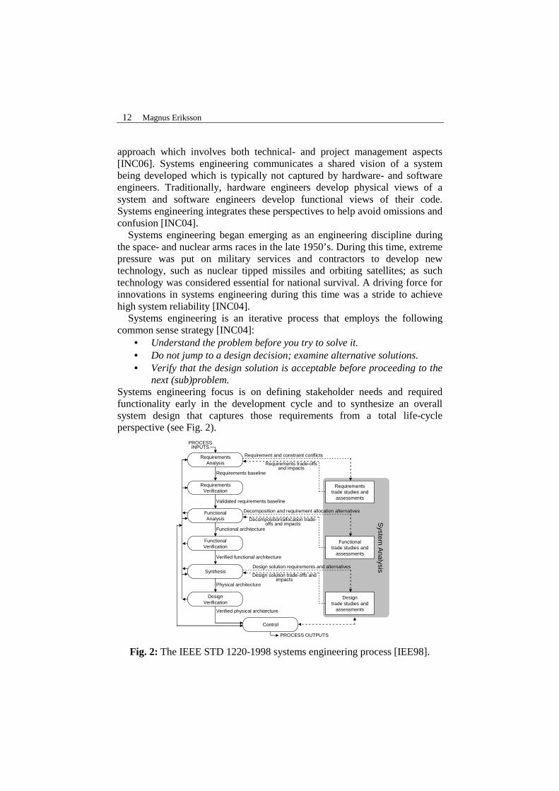
next (sub)problem. Systems engineering focus is on defining stakeholder needs and required functionality early in the development cycle and to synthesize an overall system design that captures those requirements from a total life-cycle perspective (see Fig. 2).
System
Analysis
RequirementsAnalysis
RequirementsVerification
FunctionalAnalysis
FunctionalVerification
Synthesis
DesignVerification
Control
Verified physical architecture
Physical architecture
Verified functional architecture
Functional architecture
Validated requirements baseline
Requirements baseline
Requirement and constraint conflicts
Requirementstrade studies and
assessments
Functionaltrade studies and
assessments
Designtrade studies and
assessments
Requirements trade-offs and impacts
Decomposition and requirement allocation alternatives
Decomposition/allocation trade-offs and impacts
Design solution requirements and alternatives
Design solution trade-offs and impacts
PROCESSINPUTS
PROCESS OUTPUTS
Fig. 2: The IEEE STD 1220-1998 systems engineering process [IEE98].
Kappa 13
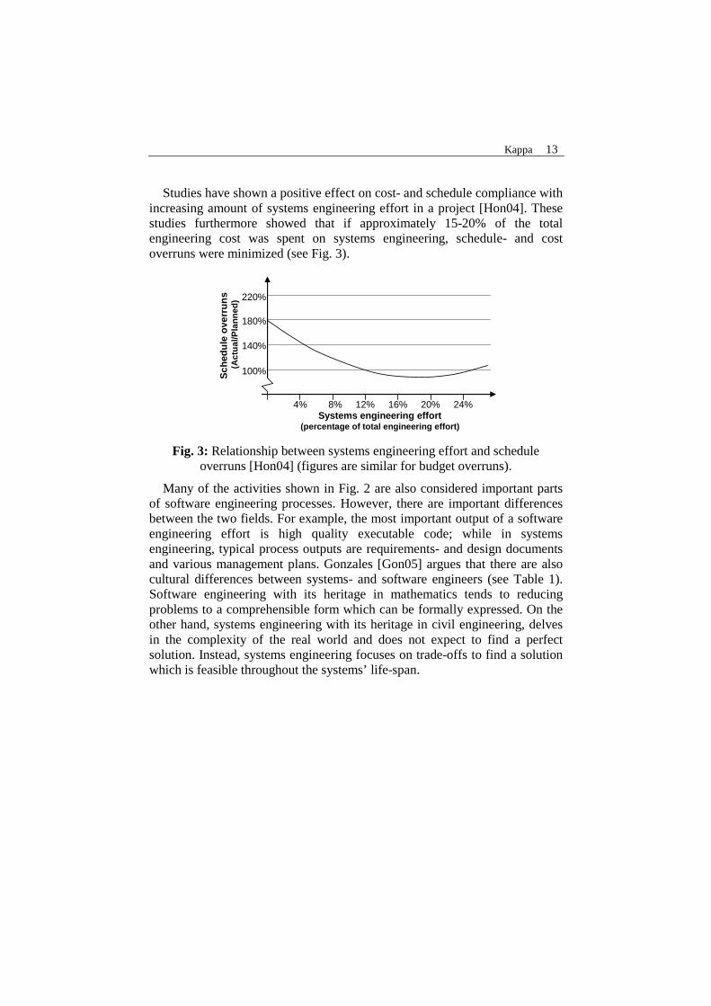
Studies have shown a positive effect on cost- and schedule compliance with increasing amount of systems engineering effort in a project [Hon04]. These studies furthermore showed that if approximately 15-20% of the total engineering cost was spent on systems engineering, schedule- and cost overruns were minimized (see Fig. 3).
4% 8% 12% 16% 20% 24%Systems engineering effort
(percentage of total engineering effort)
Sch
edu
le o
verr
un
s(A
ctu
al/P
lan
ned
)
100%
140%
180%
220%
Fig. 3: Relationship between systems engineering effort and schedule overruns [Hon04] (figures are similar for budget overruns).
Many of the activities shown in Fig. 2 are also considered important parts of software engineering processes. However, there are important differences between the two fields. For example, the most important output of a software engineering effort is high quality executable code; while in systems engineering, typical process outputs are requirements- and design documents and various management plans. Gonzales [Gon05] argues that there are also cultural differences between systems- and software engineers (see Table 1). Software engineering with its heritage in mathematics tends to reducing problems to a comprehensible form which can be formally expressed. On the other hand, systems engineering with its heritage in civil engineering, delves in the complexity of the real world and does not expect to find a perfect solution. Instead, systems engineering focuses on trade-offs to find a solution which is feasible throughout the systems’ life-span.

14 Magnus Eriksson
Table 1. Software- vs. systems engineering culture according to [Gon05].
Software Engineering Systems Engineering Fundamental beliefs and assumptions
• Engineers can reduce problems or problem solutions to a set of formalisms.
• Precisely specifying and applying methods will produce equal results regardless of the people involved.
• The software is the system.
• Formalisms help, but communication is most important.
• Collect, mix, and match methods and techniques and put them in your toolkit. Apply as appropriate; no method or technique offers any guarantees.
• The software is a system component.
Shared values
• Developing formalisms for a problem or domain is the most important step in solving the problem.
• Understanding the people involved and their interpersonal dynamics is most important.
Behavioral patterns (or customs)
• Precisely state or formalize the problem even if it requires narrowing the scope.
• Model the problem using formalisms.
• Develop a full understanding of a prospective solution’s operational aspects, and use natural language to establish an agreement.
Behavioral norms
• Avoid the messiness of systems in the real world, such as deployment, aging, poor physical environment, and chaos.
• Have a passion for new methods.
• Apply a balance of management and engineering methods to achieve the desired outcome.
• Be risk averse.
Artifacts • Artifacts include UML diagrams and user scenarios.
• Artifacts include operational scenarios and abundant management documents, such as SEMPs (systems engineering management plans), TEMPs (test and evaluation management plans), risk management plans, and so forth.
A common denominator between systems- and software engineering is, however, that systematic requirements management is considered critical for the success of large projects. Similar requirements engineering methods and tools are also used in both disciplines. Most of these methods and tools have originated in software development and were later adopted by systems engineers [Dor97]. Requirements engineering involves activities such as
Kappa 15
discovering, documenting and maintaining a set of requirements for a system [Som97]. Requirements can be divided into two main categories4 [Som97]:
• Functional requirements, which describe what the system should do. • Non-functional requirements5 (NFRs), which place constraints on how
functional requirements are implemented. A difference between systems- and software engineers in this area is however that software engineers have a tendency to neglect NFRs [Cys04]; while NFRs form a basis for the various trade-off studies in the systems engineering process. Furthermore, software engineers tend to favor concrete component-level requirements, while systems engineers focus is on high-level goals and customer requirements.
3 Software Product Lines
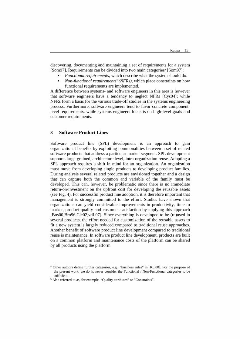
Software product line (SPL) development is an approach to gain organizational benefits by exploiting commonalities between a set of related software products that address a particular market segment. SPL development supports large-grained, architecture level, intra-organization reuse. Adopting a SPL approach requires a shift in mind for an organization. An organization must move from developing single products to developing product families. During analysis several related products are envisioned together and a design that can capture both the common and variable of the family must be developed. This can, however, be problematic since there is no immediate return-on-investment on the upfront cost for developing the reusable assets (see Fig. 4). For successful product line adoption, it is therefore important that management is strongly committed to the effort. Studies have shown that organizations can yield considerable improvements in productivity, time to market, product quality and customer satisfaction by applying this approach [Bos00,Bro96,Cle02,vdL07]. Since everything is developed to be (re)used in several products, the effort needed for customization of the reusable assets to fit a new system is largely reduced compared to traditional reuse approaches. Another benefit of software product line development compared to traditional reuse is maintenance. In software product line development, products are built on a common platform and maintenance costs of the platform can be shared by all products using the platform.
4 Other authors define further categories, e.g., “business rules” in [Kul00]. For the purpose of
the present work, we do however consider the Functional / Non-Functional categories to be sufficient.
5 Also referred to as, for example, “Quality attributes” or “Constraints”.
16 Magnus Eriksson
#1 #2 #3 #4
Cost
Project
Cost of Product Line
Total Cost withoutProduct Line
Fig. 4: Software product line payoff [Cle07].
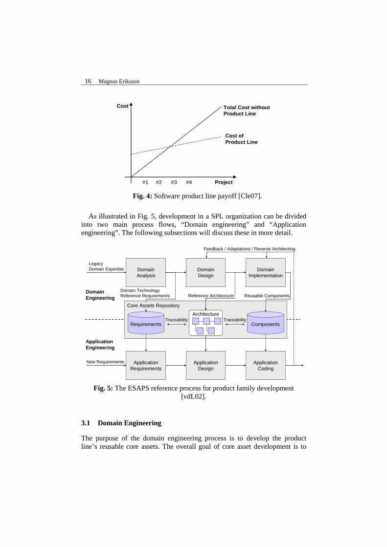
As illustrated in Fig. 5, development in a SPL organization can be divided
into two main process flows, “Domain engineering” and “Application engineering”. The following subsections will discuss these in more detail.
DomainEngineering
ApplicationEngineering
DomainAnalysis
DomainDesign
DomainImplementation
ApplicationRequirements
ApplicationDesign
ApplicationCoding
Requirements Components
Architecture
Reference Architecture Reusable ComponentsDomain TechnologyReference Requirements
TraceabilityTraceability
Feedback / Adaptations / Reverse Architecting
LegacyDomain Expertise
New Requirements
Core Assets Repository
Fig. 5: The ESAPS reference process for product family development [vdL02].
3.1 Domain Engineering
The purpose of the domain engineering process is to develop the product line’s reusable core assets. The overall goal of core asset development is to

Kappa 17
provide a production capability for products [Nor02]. As illustrated in Fig. 5, some of the key artifacts of a product line are its requirements, its architecture and its components. However, the reusable core assets also contains many other artifacts; for example test cases, budgets, schedules, specifications, etc. [Cle02]. All of these different types of artifacts are developed to be easily (re)usable within the product line.
Together with these core assets, production plans [Cle02] should also be developed. The purpose of a production plan is to describe how products are developed using core assets. For example by describing how specific tools are applied in order to use, tailor and evolve assets, how any product-unique development should be accomplished to supplement the core assets, and how products should be tested [Cle02].
As indicated by Fig. 5, the domain engineering process can be divided into three major activities:
• Domain Analysis. The activity in which commonality and variability analysis is performed in software product line development is commonly referred to as domain analysis. The input to this activity is domain expertise and technology from existing products. The main outputs from this activity are product line requirements. What is peculiar about product line requirements compared to traditional requirements is that they span several products [Cle02]. This means that some of these product-line-wide requirements must be written with variation points to be able to capture variations between individual products within a product line. Such a variation point could for example be defined as a symbolic placeholder within a textual requirement (see Fig. 6). A widely used domain analysis technique is feature modeling [Kan90,Cza04]. Feature modeling, which is a way to organize the results of the commonality and variability analysis into a tree structure, will be further discussed in section 4.1.
• Domain Design. The purpose of the domain design activity is to develop a product line architecture6 that can fulfill the product line requirements developed during domain analyses. A difference between product line architectures and conventional software architectures is that product line architectures define a set of explicitly allowed variations, representing the individual products that can be built within a product line. The product line architecture also defines the necessary mechanisms to implement these variations and thereby constrains the component implementation [Cle02]. Svahnberg and
6 A number of product line architecture design methods have been described in the literature.
Further discussion of these methods is not within the scope of this dissertation; however, a summary and comparison of some of the most well-known ones (COPA [Ame02], FAST [Wei99], FORM [Kan98], KobrA [Atk02] and QADA [Nie06]) can be found in [Mat04].

18 Magnus Eriksson
Bosch build on the work by Jacobson et al. [Jac97], and define the following product line architecture variability mechanisms [Sva00]: Inheritance, Extension points, Parameterization using templates and macros, Module interconnection languages, Generation using higher-level languages and Compile-time selection of implementations (#ifdef’s).
• Domain Implementation. The domain implementation activity aims to produce the reusable software, based on the product line requirements and the constraints posed by the product line architecture. Even though software product line development typically employs a form of component-based development [Szy02], a few differences exist compared to the view of components in other settings. For example, product line components are typically not instantiated independently. Product line components are assembled in a prescribed way specified by their production plans and the product line architecture [Cle02]. Furthermore, product line components implement variability mechanisms specified by the product line architecture [Bos00]. If variability is required in traditional components, the variability is typically managed by maintaining separate releases of the required components. Fig. 7 shows an overview of the activities and artifacts leading up to component design and implementation in a software product line context.
CMD-01220:It shall be possible to define up to a maximum of @MAX_NUM_CMD command sub-systems where MAX_NUM_CMD can not be greater than 255.
Fig. 6: An example of a requirement variation point [Man00]
Componentimplementation
Componentdesign
Softwarearchitectural
design
Variabilityanalysis
Componentrequirements
Constraints & rules
Legacycode
Fig. 7: Activities and deliverables in software product line component development [Bos00].
Kappa 19
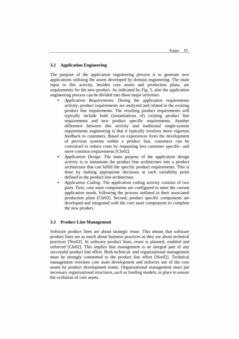
3.2 Application Engineering
The purpose of the application engineering process is to generate new applications utilizing the assets developed by domain engineering. The main input to this activity, besides core assets and production plans, are requirements for the new product. As indicated by Fig. 5, also the application engineering process can be divided into three major activities:
• Application Requirements. During the application requirements activity, product requirements are analyzed and related to the existing product line requirements. The resulting product requirements will typically include both (instantiations of) existing product line requirements and new product specific requirements. Another difference between this activity and traditional single-system requirements engineering is that it typically involves more vigorous feedback to customers. Based on experiences from the development of previous systems within a product line, customers can be convinced to reduce costs by requesting less customer specific- and more common requirements [Cle02].
• Application Design. The main purpose of the application design activity is to instantiate the product line architecture into a product architecture that can fulfill the specific product requirements. This is done by making appropriate decisions at each variability point defined in the product line architecture.
• Application Coding. The application coding activity consists of two parts. First, core asset components are configured to meet the current application needs, following the process outlined in their associated production plans [Cle02]. Second, product specific components are developed and integrated with the core asset components to complete the new product.
3.3 Product Line Management
Software product lines are about strategic reuse. This means that software product lines are as much about business practices as they are about technical practices [Nor02]. In software product lines, reuse is planned, enabled and enforced [Cle02]. This implies that management is an integral part of any successful product line effort. Both technical- and organizational management must be strongly committed to the product line effort [Nor02]. Technical management oversees core asset development and enforces use of the core assets by product development teams. Organizational management must put necessary organizational structures, such as funding models, in place to ensure the evolution of core assets.

20 Magnus Eriksson
Studies have shown that several different organizational models are used for software product line development in industry [Bos00]. These organizational models include both specialized organizational units responsible for the core assets, as well as models where the core assets are a sheared responsibility among several business units. Bosch proposes the following influencing factors that affects the choice of organizational model [Bos00]: Size of the organization, Geographical distribution, Project management maturity, Organizational culture and Type of products.
4 Modeling
4.1 Feature Modeling
As mentioned in section 3.1, a widely used domain analysis technique in software product line development is feature modeling. Kang et al. first proposed using feature models in 1990 as part of Feature Oriented Domain Analysis (FODA) [Kan90]. Kang et al. define a feature as: “… a prominent or distinctive user-visible aspect, quality, or characteristic of a software system or systems …” In feature models, system features are organized into trees of AND and OR nodes that represent the commonalities and variations within a family of related systems. General features are located at the top of the tree and more refined features are located below.
Originally, FODA described “Mandatory”, “Optional” and “Alternative” features, and the additional feature composition rules “requires” and “mutually exclusive with” (mutex). Mandatory features are available in all systems within a family. Optional features represent variability within a family that may or may not be included in products. Alternative features represent an “exactly-one-out-of-many” selection among a set of features. A “requires” relationship indicates that a feature depends on some other feature to make sense in a system. A “mutex” relationship between two features indicates that both features can not be included in the same system. Fig. 8 shows an example of a simple feature model in the FODA notation.
Kappa 21
Car
Transmission Engine Air conditioning
AutomaticManual
Alternativefeatures
Mandatoryfeatures
Optionalfeatures
Sunroof
Composition rule:“Air conditioning” is mutually exclusive with “Sunroof”Composition rule:“Air conditioning” is mutually exclusive with “Sunroof”
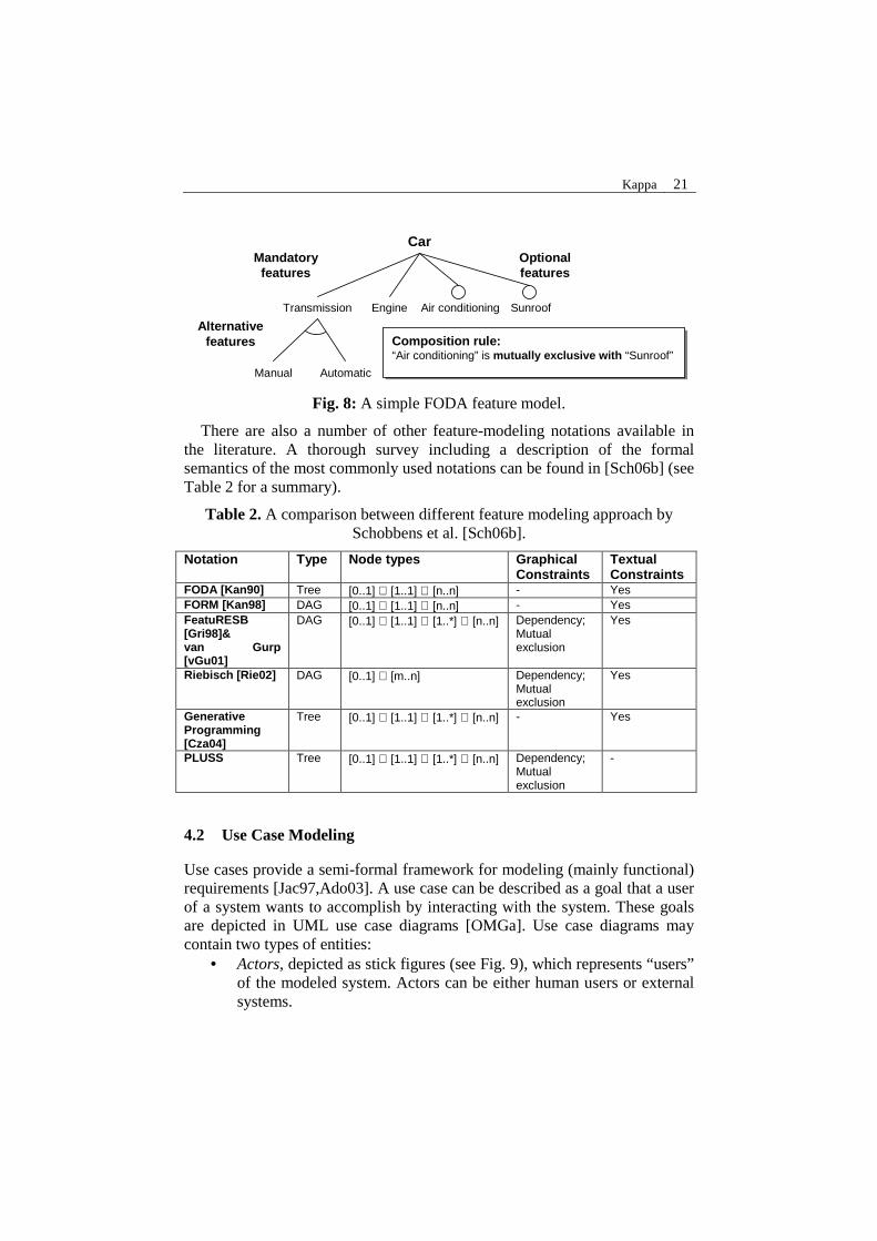
Fig. 8: A simple FODA feature model.
There are also a number of other feature-modeling notations available in the literature. A thorough survey including a description of the formal semantics of the most commonly used notations can be found in [Sch06b] (see Table 2 for a summary).
Table 2. A comparison between different feature modeling approach by Schobbens et al. [Sch06b].
Notation Type Node types Graphical Constraints
Textual Constraints
FODA [Kan90] Tree [0..1] ∪ [1..1] ∪ [n..n] - Yes FORM [Kan98] DAG [0..1] ∪ [1..1] ∪ [n..n] - Yes FeatuRESB [Gri98]& van Gurp [vGu01]
DAG [0..1] ∪ [1..1] ∪ [1..*] ∪ [n..n] Dependency; Mutual exclusion
Yes
Riebisch [Rie02] DAG [0..1] ∪ [m..n] Dependency; Mutual exclusion
Yes
Generative Programming [Cza04]
Tree [0..1] ∪ [1..1] ∪ [1..*] ∪ [n..n] - Yes
PLUSS Tree [0..1] ∪ [1..1] ∪ [1..*] ∪ [n..n] Dependency; Mutual exclusion
-
4.2 Use Case Modeling
Use cases provide a semi-formal framework for modeling (mainly functional) requirements [Jac97,Ado03]. A use case can be described as a goal that a user of a system wants to accomplish by interacting with the system. These goals are depicted in UML use case diagrams [OMGa]. Use case diagrams may contain two types of entities:
• Actors, depicted as stick figures (see Fig. 9), which represents “users” of the modeled system. Actors can be either human users or external systems.

22 Magnus Eriksson
• Use cases, depicted as ellipses (see Fig. 9), which can have association relationships to actors. An association relationship between an actor and a use case means that the actor can communicate with the use case. That is, either initiate or participate in the behavior specified in the use case.
Use cases are further specified by a number of use case scenarios. These scenarios, which describe interaction between a system and its actors, are typically described informally, in natural language. However, also UML Sequence diagrams and Activity diagrams [OMGa] are popular notations for describing use case scenarios.
Customer Withdraw cash Bank Mainframe
Fig. 9: An example of a UML use case diagram.
Typically, for each use case in a use case model, there is also a corresponding use case realization in a design model [Bit03]. A use case realization is a description of how different design elements collaborate to perform the tasks defined by a specific use case (see Fig. 10) [Kru00]. The main purpose of a use case realization is to provide a bridge between requirements modeled as a use case and a systems’ design (i.e. traceability). Use case realizations are often described using UML Sequence or Collaboration diagrams [OMGa].

Kappa 23
Use Case Model
Use Case Model Hierarchy
Use Case SpecificationIntro...Main Success Scenario
Alternative Scenarios...Exceptional Scenarios...
Use Case Package 1
Use Case Package 1.2
Use Case Package 1.1
Use Case Package 1.3
Use Case Diagram
Actor 1
Use Case 1
Use Case 2
Actor 1 System
Design Model
Use Case Realization
<<realize>>
Use Case Realization: Use Case 1
:Actor
: a
: c
: b
1: ...
2: ...
4: ...
6: ...
5: ...
: d
7: ...
8: ...3: ...
Fig. 10: An overview of use case modeling artifacts and concepts.
4.3 Change Case Modeling
An interesting extension to use case modeling, from the perspective of software product lines, is known as change case modeling. Change cases, proposed by Ecklund et al. [Eck96], are basically use cases that specify anticipated changes to a system over its foreseeable lifetime. Compared to use cases, change cases provide the additional relation “impact link”7. The purpose of this relation is to provide traceability to use cases whose implementations are affected, if the change case is realized (see Fig. 11). Change cases enable product line designers to model and plan for anticipated future requirements in a domain [Cle02].
7 We proposed a change case meta-model in [Eri06a].

24 Magnus Eriksson
Customer <<change case>>Withdraw foreign currency
Bank Mainframe
Withdraw cash
<<impacts>>
Fig. 11: A change case example in a UML use case diagram.
5 Summary of Contributions
The contributions of the present dissertation can be divided into two main parts, the FAR approach (see Paper I) and the PLUSS approach (see Papers II, III, IV and V):
The FAR (Functional Architectures by use case Realizations) approach is a use case driven methodology to allocate system requirements to the elements of a system architecture. Based on these allocations, the FAR approach also provides means to derive requirements for each of these system elements (requirements flowdown). The FAR approach thereby provides a framework for end-user goal-based functional-decomposition and scenario-based requirements flowdown as described in our research hypothesis (see section 1.3).
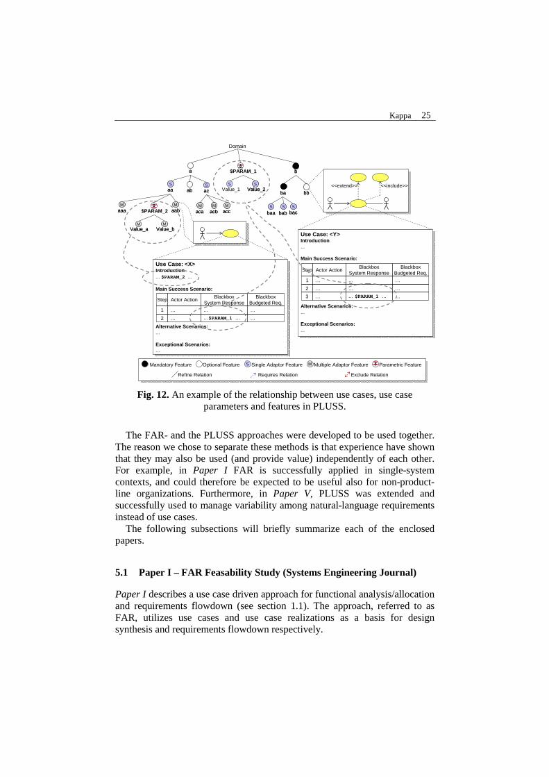
PLUSS (Product Line Use case modeling for Systems- and Software engineering) is an approach to manage variability in use case models. PLUSS provide means to develop and maintain a common model for a whole family of products. Following the work by Griss et al. on FeaturRSEB [Gri98], PLUSS provides means to systematically manage variability by integrating feature modeling and use case modeling. PLUSS furthermore introduce textual use cases parameters (see Fig. 12). PLUSS thereby provides a framework for variability management as described in our research hypothesis (see section 1.3).
Kappa 25
<<extend>>
Domain
bb
Sbac
Sbac
S
baaS
baaS
babS
bab
bbbbbaba
aa
MaccM
accM
acbM
acb
SacSac
SaaS
aa
Maaa
Maaa
MaabM
aab
abab
Maca
Maca
Use Case: <Y>Introduction...
Main Success Scenario:
Alternative Scenarios:...
Exceptional Scenarios:...
Use Case: <Y>Introduction...
Main Success Scenario:
Alternative Scenarios:...
Exceptional Scenarios:...
Step Actor ActionBlackbox
System ResponseBlackbox
Budgeted Req.
1 … … …
2 … … …
3 … …… $PARAM_1 …
<<include>>
$$PARAM_1
SValue_2
SValue_2
SValue_1
$$PARAM_2
MValue_b
MValue_b
MValue_a
MValue_a
S Single Adaptor FeatureMandatory Feature Optional Feature M Multiple Adaptor Feature
Requires Relation Exclude RelationRefine Relation
Parametric Feature $
Use Case: <X>Introduction... $PARAM_2 ...
Main Success Scenario:
Alternative Scenarios:...
Exceptional Scenarios:...
Use Case: <X>Introduction... $PARAM_2 ...
Main Success Scenario:
Alternative Scenarios:...
Exceptional Scenarios:...
Step Actor Action BlackboxSystem Response
BlackboxBudgeted Req.
1 … … …
2 … …$PARAM_1 … …
Fig. 12. An example of the relationship between use cases, use case parameters and features in PLUSS.
The FAR- and the PLUSS approaches were developed to be used together.
The reason we chose to separate these methods is that experience have shown that they may also be used (and provide value) independently of each other. For example, in Paper I FAR is successfully applied in single-system contexts, and could therefore be expected to be useful also for non-product-line organizations. Furthermore, in Paper V, PLUSS was extended and successfully used to manage variability among natural-language requirements instead of use cases.
The following subsections will briefly summarize each of the enclosed papers.
5.1 Paper I – FAR Feasability Study (Systems Engineering Journal)
Paper I describes a use case driven approach for functional analysis/allocation and requirements flowdown (see section 1.1). The approach, referred to as FAR, utilizes use cases and use case realizations as a basis for design synthesis and requirements flowdown respectively.

26 Magnus Eriksson
The paper also presents an empirical study where FAR is applied and evaluated in two large-scale defense projects within Hägglunds. The results indicate that the approach performs better than the previously used approach to manage the system functional view in the organization.
5.2 Paper II – PLUSS Feasability Study (SPLC’05)
Paper II describes a product line use case modeling approach which provides means to develop and maintain a common and complete use case model for a whole product family (the PLUSS approach). A UML meta-model is presented which also includes use case realizations in the product line model.
To manage variability in this product line model, an extended version of FODA feature models is used, combined with textual parameters. The feature modeling extension enables modeling of “at-least-one-out-of-many”-selections (also known as “OR” features) which were not present in original FODA. This extension was required to be able to capture all variants that can exist in use case models. Together with this extension, a new feature modeling notation was proposed. As indicated by the comparison in Table 2 (see section 4.1), the PLUSS feature modeling notation used in the present work is not more expressive than other available notations. Instead, the improvements proposed are mainly esthetical with the purpose of improving readability (e.g. by using color-coded feature symbols).
Paper II also presents an empirical study where PLUSS was applied to develop core assets for one of Hägglunds subsystem product lines. The results indicated that the approach performs better than modeling according to the styles and guidelines specified by RUP [Kru00], which were previously used in the organization.
5.3 Paper III – The PLUSS Toolkit (ASE’05)
Paper III describes how commercially available CASE tools can be adapted and utilized to support the PLUSS approach. A toolkit is presented which extends the UML modeling tool IBM-Rational Rose and the requirements management tool Telelogic DOORS. DOORS is utilized to manage PLUSS models and Rose is used for drawing feature graphs and UML diagrams. Appropriate reports (use case model survey, use case specifications, feature model survey) are generated from DOORS as MS Word documents (see Fig. 13).

Kappa 27
Feature Model,Use Case Specifications
andUse Case Realizations
DOORS
Feature Graphand
UML Diagrams
Rose
Repository ofPublished Reports
Software CM SystemMS Word Reports
Feature Model,Use Case Specifications
andUse Case Realizations
DOORS
Feature Graphand
UML Diagrams
Rose
Repository ofPublished Reports
Software CM SystemMS Word Reports
Fig. 13: An overview of the PLUSS toolkit.
An empirical evaluation of the PLUSS toolkit was performed and published in [Eri06b] (see section 5.6). The evaluation showed the toolkit allows subjects to work effectively. However, a problem raised was that DOORS and Rose were not integrated well enough. This unsatisfactory integration led to time-consuming and to some extent error-prone manual synchronization work between the tools. In later versions of the toolkit we have therefore minimized the use of Rose by improving the DOORS extensions.
5.4 Paper IV – PLUSS Refinement (Communications of the ACM)
Paper IV describes a refinement regarding use cases parameters in PLUSS. Further experience using PLUSS at Hägglunds has shown that the concept of local- and global parameters described in Paper II and Paper III is not as intuitive as initially indicated. The use of parameters has therefore been modified to only offer one type (see Paper IV and Paper V for details).
5.5 Paper V – PLUSS Validation Study (Submitted)
Paper V describes how the PLUSS approach can be extended and used for managing natural-language product line requirements specifications. The paper also includes a multiple-case study which covers two different product line projects at Hägglunds with (in total) eight product instances. These projects are compared to historical projects employing clone-and-own reuse of requirements specifications. The collected data indicate that PLUSS performs better than the clone-an-own reuse approach applied before in the organization.

28 Magnus Eriksson
5.6 Related Publications
The following publications are related to, but not included in this dissertation:
M. Eriksson, J. Börstler & K. Borg (2004): Marrying Features and Use Cases for Product Line Requirements Modeling of Embedded Systems, Proceedings of the Fourth Conference on Software Engineering Research and Practice in Sweden (SERPS'04), 73-82.
− This paper presents an approach to system-level domain modeling that utilizes feature models and use cases that are integrated into a coherent two-layer product family model. The approach presented here was later refined and split-up into the FAR- and the PLUSS approaches discussed above.
M. Eriksson, K. Borg & J. Börstler (2006): The FAR Approach - Functional Analysis/Allocation and Requirements Flowdown Using Use Case Realizations, Proceedings of the Sixteenth Annual International Symposium of the International Council on Systems Engineering (INCOSE'06).
− This paper is an introduction to the FAR approach. The approach is illustrated throughout the paper using an Automatic Teller Machine (ATM) example. This paper received the 2006 INCOSE – Brian Mar Award (Best Student Paper). This paper was later considerably revised and included in Paper I in this dissertation.
M. Eriksson, J. Börstler & K. Borg (2006): Performing Functional Analysis/Allocation and Requirements Flowdown Using Use Case Realizations - An Empirical Evaluation, Proceedings of the Sixteenth Annual International Symposium of the International Council on Systems Engineering (INCOSE'06).
− This paper presents an empirical study in which the FAR approach is applied and evaluated in two large-scale defense projects. The results indicated that the FAR approach performed better than the previously used approach at Hägglunds. This paper was later considerably revised and included in Paper I in this dissertation.
M. Eriksson, H. Morast, J. Börstler & K. Borg (2006): An Empirical Evaluation of the PLUSS Toolkit, Technical Report, Dept. of Computing Science, Umeå University, UMINF-06.31.
− This paper presents an empirical evaluation of the CASE tool extensions developed to support the PLUSS approach. The evaluation was designed as a blocked subject-project study [Sea99] including data collection from two different projects. Data was collected using

Kappa 29
observation, document studies, questionnaires and interviews with eight subjects. Results indicated that the toolkit allows developers to work effectively. Some minor shortcomings of the toolkit were however identified and we therefore propose certain improvements. Some of these improvements were later realized; however, the details regarding these improvements have not yet been published.
T. Gorschek, M. Svahnberg, A. Borg, J. Börstler, M. Eriksson, A, Loconsole & K. Sandahl (2007): A Replicated Controlled Empirical Evaluation of a Requirements Abstraction Model, Information and Software Technology Journal, Vol. 49, No 7, 790-805.
− This paper presents an evaluation of a requirements abstraction model (not related to PLUSS or FAR). The evaluation’s primary goal was to test the model’s usability and usefulness in a lab environment prior to large scale industry piloting. The evaluation consisted of a formal experiment using 179 subjects from three different Swedish universities. The results provided a strong indication that the model was indeed both useful and usable.
M. Eriksson, J. Börstler & K. Borg (2007): Anchoring the Product Line Process – Tailoring the RUP Life-Cycle Model to Software Product Line Development, Technical Report, Dept. of Computing Science, Umeå University, UMINF-07.18
− This paper presents an extended life-cycle model tailored to the specific needs of domain- and application engineering projects using RUP. The purpose of this work was to provide a basis for product line organizations to perform systematic phase reviews. Tailored phase reviews will help organizations to anchor the product line process throughout a product line’s life-cycle. As a basis for the proposed model, SEI’s framework for product line practice and our experiences applying RUP in a product line context were used.
6 Summary and Conclusions
In this dissertation, methods and tools related to functional decomposition, requirements flowdown and management of product line requirements artifacts have been proposed. The over-all purpose of these methods and tools has been to provide an improved reuse infrastructure for systems engineering artifacts and their resulting detailed-design solutions (see hypothesis in section 1.3).

30 Magnus Eriksson
Four empirical studies (see Paper I, Paper II, Paper V and [Eri06b]) have also been performed with the purpose of evaluating the proposed methods and tools in a realistic industrial environment. These studies have indicated that these methods and tools, compared to the previously used methods and tools, indeed provide an improved reuse infrastructure. However, further studies are desirable to verify these results (see discussion in section 7.2 below).
7 Future Work
The studies presented in this dissertation have pointed to several interesting openings for future work in the area. Some examples are improved support for managing non-functional requirements; documenting design rationale; integrating metrics for early cost estimates, etc. However, from a practitioner and a research perspective, we consider the following two areas to be most important.
7.1 Support for Model Driven Engineering
From a practitioner perspective, an important supplement to the present work would be improved support for model-driven engineering [Sch06a]. In the present work, mainly natural language notations have been utilized to describe system behavior. However, as we mention in Paper I, the proposed methods are likely to be applicable also using more formal notations, such as message-sequence charts of finite-state machines. Use of more formal notations is a prerequisite for being able to apply FAR and PLUSS in a model-driven context.
7.2 Follow-up Studies
From a research perspective, it would be interesting to perform follow-up studies to verify whether the positive results reported in this dissertation are still valid when the proposed methods and tools are applied in other industrial contexts.

Kappa 31
8 References
[Ado03] Adolph S., Bramble P., Cockburn A., Pols A.: Patterns for Effective Use Cases, Addison-Wesley (2003)
[Ame00] America P., Obbink H., Muller J., van Ommering R.: COPA: A Component-Oriented Platform Architecting Method for Families of Software Intensive Electronic Products, Proceedings of the First Conference on Software Product Line Engineering (2000)
[Atk02] Atkinson C., Bayer J., Bunse C., Kamsties E., Laitenberger O., Laqua R., Muthig D., Paech B., Wüst and Zettel J.: Component-based Product Line Engineering with UML, Addison-Wesley (2002)
[BAE03] BAE Systems Hägglunds AB: Processutvärdering vid Alvis Hägglunds AB i Örnsköldsvik, Internal Report (2003)
[Bas02] Basili V., McGarry F., Pajerski R., Zelkowitz M.: Lessons learned from 25 years of process improvement: the rise and fall of the NASA software engineering laboratory, Proceedings of the 24th International Conference on Software Engineering (2002) 69-79.
[Bit03] Bittner K., Spence I.: Use Case Modeling, Addison-Wesley (2003)
[Bos00] Bosch J.: Design & Use of Software Architectures, Addison-Wesley (2000)
[Bro96] Brownsword L., Clements P.: A Case Study in Successful Product Line Development, CMU/SEI-96-TR-016, Pittsburgh, PA: Carnegie Mellon University, Software Engineering Institute (1996)
[Bör97] Börstler J., Boman T., Sigerud K.: A pragmatic approach to Use Cases, Technical Report UMINF-97.24, Department of Computing Science, Umeå University, Sweden (1997)
[Cle02] Clements P., Northrop L.: Software Product Lines, Practices and Patterns, Addison-Wesley (2002)
[Cle07] Clements P.: It Takes Two, news@sei, Vol 6, No. 4, Fourth quarter 2003, Available at: http://www.sei.cmu.edu/news-at-sei/columns/software-product-lines/2003/4q03/software-product-lines-4q03.htm, Accessed: (October 14, 2007)
[Coc02] Cockburn A.: Agile Software Development, Addison-Wesley (2002)
[Cys04] Cysneiros L., Sampaio J.: Nonfunctional Requirement: From Elicitation to Conceptual Models, IEEE Transactions on Software Engineering, Vol. 30, No. 5 (May 2004)
[Cza04] Czarnecki K., Eisenecker U.: Generative Programming – Methods, Tools, and Applications, Addison-Wesley (2004)
[Dor97] Dorfman M.: Requirements Engineering, Software Requirements Engineering, Los Alamitos, CA, IEEE Computer Society Press, (1997)
[Eck96] Ecklund E., Delcambre L., Freiling M.: Change Cases - Use Cases that Identify Future Requirements, Proceedings of OOPSLA 96, San Jose, Ca (1996) 342-358.
[Elf07] Elfatatry A.:Dealing with Change – Components Versus Services, Communications of the ACM, Vol. 50, No. 8 (August 2007) 35-39.
32 Magnus Eriksson
[Eri04] Eriksson M., Börstler J., Borg K.: Marrying Features and Use Cases for Product Line Requirements Modeling of Embedded Systems, Proceedings of the Fourth Conference on Software Engineering Research and Practice in Sweden (2004) 73-82.
[Eri06a] Eriksson M.: An Approach to Software Product Line Use Case Modeling, Licentiate Dissertation, Dep. of Computing Science, Umeå University, UMINF-06.01, ISSN 0348-0542, ISBN 91-7264-023-5, (2006)
[Eri06b] Eriksson M., Morast H., Börstler J., Borg K.: An Empirical Evaluation of the PLUSS Toolkit, Technical Report, Dept. of Computing Science, Umeå University, UMINF-06.31 (2006)
[For96] Forsberg K., Mooz H.: Systems Engineering Overview, In Software Requirements Engineering, Los Alamitos, CA, IEEE Computer Society Press, 44-72.
[Gon05] Gonzales R.: Developing the Requirements Discipline: Software vs. Systems, IEEE Software (March/April 2005) 59-61.
[Gor06] Gorschek T., Wohlin C., Garre P., Larsson S.: A Model for Technology Transfer in Practice, IEEE Software (November/December 2006) 88-95.
[Gri98] Griss M., Favaro J., d’Alessandro M.: Integrating Feature Modeling with the RSEB, Proceedings of the Fifth International Conference on Software Reuse, Vancouver, BC, Canada (June 2-5 1998) 76-85.
[Hir02] Hirsch M.: Making RUP Agile, Proceedings of OOPSLA’02 (November 2002).
[Hon04] Honor E.: Understanding the Value of Systems Engineering, Proceedings of the 14th INCOSE International Symposium (2004)
[IEE99] IEEE 1220-1998, Standard for Application and Management of the Systems Engineering Process, ISBN 0-7381-1543-6 (January 1999)
[INC04] International Council on Systems Engineering, Systems Engineering Handbook Version 2a, INCOSE-TP-2003-016-02 (June 2004)
[INC06] International Council on Systems Engineering, Systems Engineering Handbook Version 3, INCOSE-TP-2003-002-03 (June 2006)
[ISO00] ISO 9001:2000, Quality Management Systems – Requirements
[ISO98a] ISO/IEC 15504-1:1998, Information technology – Process assessment – Part 1: Concepts and vocabulary.
[ISO98b] ISO/IEC 15504-2:1998, Software Engineering – Process assessment – Part 2: Performing an assessment.
[ISO98c] ISO/IEC 15504-3:1998, Information technology – Process assessment – Part 3: Guidance on performing an assessment.
[ISO98d] ISO/IEC 15504-4:1998, Information technology – Process assessment – Part 4: Guidance on use for process improvement and process capability determination.
[ISO99] ISO/IEC 15504-5:1999, Information technology – Process assessment – Part 5: An exemplar Process Assessment Model.

Kappa 33
[Jac97] Jacobson I., Griss M., Jonsson P.: Software Reuse – Architecture, Process and Organization for Business success, Addison-Wesley (1997)
[Jac99] Jacobson I., Booch G., Rumbaugh J.: The Unified Software Development Process, Addison-Wesley (1999)
[Kai02] Kaindl H., Brinkkemper S., Bubenko J., Farbey B., Greenspan S., Heitmeyer C., Leite J., Mead N. Mylopoulos J. Siddiqi J.: Requirements Engineering and Technology Transfer – Obstacles Incentives and Improvement Agenda, Requirements Engineering, Vol. 7 (2002) 113-123.
[Kan90] Kang K. Cohen S., Hess J., Novak W., Peterson A.: Feature Oriented Domain Analysis (FODA) Feasibility Study, Technical Report CMU/SEI-90-TR-021, Software Engineering Institute, Carnegie Mellon University, Pittsburgh, PA (1990)
[Kan98] Kang K., Kim S., Shin E., Huh M.: Form: A Feature-Oriented Reuse Method with Domain Specific Reference Architectures, Annals of Software Engineering, vol. 5 (1998) 143-168.
[Kit95] Kitchenham B., Pickard L., Pfleeger S.: Case Studies for Method and Tool Evaluation, IEEE Software, Vol. 12 Nr. 45 (1995) 52-62.
[Kit98] Kitchenham B., Pickard L.: Evaluating Software Eng. Methods and Tools Part 10: Designing and Running a Quantitative Case Study, Software Engineering Notes, Vol. 23, No. 3 (May 1998) 20-22.
[Kit04] Kitchenham B.: Procedures for Performing Systematic Reviews, NITCA Technical Report 0400011T.1 (July 2004)
[Kru00] Kruchten P.: The Rational Unified Process: An Introduction, Second Edition, Addison-Wesley (2000)
[Kul00] Kulak D., Guiney E.: Use Cases – Requirements in Context, Addison-Wesley (2000)
[Let05] Lethbridge T., Sim S., Singer J.: Studying Software Engineers: Data Collection Techniques for Software Field Studies, Empirical Software Engineering Journal, vol. 10 (2005) 311-341.
[Lyk00] Lykins H., Friedenthal S., Meilich A.: Adapting UML for an Object Oriented Systems Engineering Method (OOSEM), Proceedings of the 10´th Annual International Symposium of the International Council on Systems Engineering (INCOSE'00), International Council on Systems Engineering, 2000.
[Man00] Mannion M., Lewis O., Kaindl H., Montroni G., Wheadon J.: Representing Requirements of Generic Software in an Application Family Model, Proceedings of the 6’th International Conference on Software Reuse (2000) 153-169.
[Mat04] Matinlassi M.: Comparison of Software Product Line Architecture Design Methods: COPA, FAST, FORM, KobrA and QADA, Proceedings of the 26th International Conference on Software Engineering ICSE’04 (2004) 127-136.
34 Magnus Eriksson
[Moy96] Moynihan T.: An experimental comparison of object-orientation and functional-decomposition as paradigms for communicating system functionality to users, Journal of Systems and Software, Vol. 33, Issue 2, (May 1996) 163-169.
[NAT07] NATO: NATO Quality Assurance Requiremetns for Design, Devlopment and Production - AQAP 2110, Edition 2 , Available at: http://www.nato.org (November 2006)
[Nie06] Niemelä E.: QADA – Quality-driven Architecture Design and Architecture Analysis, Available at: http://www.vtt.fi/qada/, Accessed (January 15, 2006)
[Nor02] Northrop L.: SEI’s Software Product Line Tenets, IEEE Software (July/August 2002) 32-40.
[OMGa] Object Management Group: The Unified Modeling Language, Version 2.0, Available at: http://www.uml.org (2005)
[OMGb] Object Management Group: OMG Systems Modeling Language, Available at: http://www.omgsysml.org (2007)
[Par76] Parnas D.: On the design and development of product families, IEEE Transactions on Software Engineering, vol.2, no. 1 (1976) 1-9.
[Pfl99] Pfleeger S.: Understanding and improving technology transfer in software engineering, Journal of Systems and Software, Vol. 47 (1999) 111-124.
[Pfl00] Pfleeger S., Mendezes W.: Marketing Technology to Software Practitioners, IEEE Software, (January/February 2000) 27-33.
[Pot93] Potts C.: Software-Engineering Research Revisited, IEEE Software (September 1993) 19-28.
[Ric00] Rickman D.: A Process for Combining Object Oriented and Structured Analysis and Design, Proceedings of the 3’rd Annual Systems Engineering and Supportability Conference, National Defense Industrial Association – NDIA (2000)
[Rie02] Riebisch M., Bollert K., Streitferdt D., Philippow I.: Extending Feature Diagrams with UML Multiplicities. Proceedings of the Sixth Conference on Integrated Design and Process Technology (IDPT2002), Pasadena, CA, (June 2002).
[Sch06a] Schmidt D.: Model Driven Engineering, IEEE Computer, (February 2006) 25-31.
[Sch06b] Schobbens P., Heymans P., Trigaux J.: Feature Diagrams: A Survey and a Formal Semantics, Proceedings the 14th IEEE International Requirements Engineering Conference (2006)
[Sea99] Seaman C.: Qualitative Methods in Empirical Studies of Software Engineering, IEEE Transactions on Software Engineering (July/August 1999) 557-572.
[SEI07] Software Engineering Institute: Product Line Hall of fame, Available at: http://www.sei.cmu.edu/productlines/plp_hof.html, Accessed: (October 28, 2007)
[Som97] Sommerville I., Sawyer, P.: Requirements Engineering, A good practices guide, Wiley (1997)
Kappa 35
[Sva00] Svahnberg M., Bosch, J.: Issues Concerning Variability in Software Product Lines, Proceedings of the Third International Workshop on Software Architectures for Product Families (2000) 50-60.
[Szy02] Szyperski C., Gruntz D., Murer S.: Component Software ─ Beyond Object-Oriented Programming, Second Edition, Addison-Wesely (2002)
[vdL02] van der Linden F.: Engineering Software Architectures, Processes and Platforms for System Families - ESAPS Overview, Proceedings of the Second International Conference on Software Product Lines, San Diego, CA, USA (August 2002) 383-397.
[vdL07] van der Linden F., Schmid K., Rommes E.: Software Product Lines in Action – The Best Industrial Practice in Product Line Engineering, Springer Verlag (2007)
[vGu01] van Gurp J., Bosch J., Svahnberg M.: On the Notion of Variability in Software Product Lines, Proceedings of the Working IEEE/IFIP Conference on Software Architecture WZCSA'01, (2001)
[Wei99] Weiss D., Lai C., Tau R.: Software product-line engineering: a family-based software development process, Addison-Wesley (1999)
[Why84] Whyte W.: Learning from the field: A Guide from Experience, Bevery Hills, CA, Sage (1984)