
Engineering Failure Analysis - UM Repositoryrepository.um.edu.my/86003/1/Failure analysis on a...
10
Failure analysis on a primary superheater tube of a power plant J. Purbolaksono a, * , J. Ahmad b , L.C. Beng b , A.Z. Rashid a , A. Khinani a , A.A. Ali a a Department of Mechanical Engineering, Universiti Tenaga Nasional, Km 7 Jalan Kajang-Puchong, Kajang 43009, Selangor, Malaysia b Kapar Energy Ventures Sdn Bhd, Jalan Tok Muda, Kapar 42200, Malaysia article info Article history: Received 16 March 2009 Received in revised form 23 April 2009 Accepted 25 April 2009 Available online xxxx Keywords: Primary superheater tube Failure analysis Hardness Clinker Short-term overheating abstract In this paper failure analysis on the SA213-T12 superheater tube by visual inspection, in situ measurements of hardness and finite element analyses is presented. A primary superheater tube has failed with a wide open burst after running at around 28,194 h. Heavy clinkers were found to almost entirely cover the primary superheater region. In situ hard- ness measurements were carried out on the selected primary superheater first row tubes at the middle region between furnace rear screen tube and primary superheater blower flow path. Hardness measurements are also taken on the as-received failed tube. Finite element analyses on possible features prior to failure are also conducted in order to illustrate and deduce the failure mechanism and failure root cause. Localized short-term overheating of the tube due to localized and concentrated flue gas flow resulted in a failure of the pri- mary superheater tube. Ó 2009 Published by Elsevier Ltd. 1. Introduction Superheater tubes are the highest failure location as reported by French [1]. Jones [2] also reported creep failure problems including superheater tube failure and indicated that under which the failures occurred the conditions of temperature and time are deduced from the morphology of fracture and the change in microstructure. Detailed discussions on superheater tube failures have been discussed by French [1] and Port and Herro [3]. This paper presents failure analysis on the SA213-T12 superheater tubes by visual inspection, in situ measurements of hardness and finite element analyses. It was reported that a primary superheater tube has failed with wide open burst. Con- dition of the site at the time of failure showed heavy clinkers almost entirely covering the primary superheater region. In situ hardness measurements were carried out on the selected primary superheater first row tubes at the middle region between furnace rear screen tube and primary superheater blower flow path to estimate the average operating metal temperature under the normal service condition. Microscopic examinations are carried out on unruptured parts of the as-received tube. Finite element analyses on possible features prior to failure are carried out in order to illustrate and deduce the failure mech- anism and failure root cause. The finite element simulations are carried out by using software package of ANSYS [4]. 2. Operation facts and condition of failure region New SA213-T12 primary superheater first row tubes were fitted in the boiler unit in August 2004. The tubes have outer diameter of 50.8 mm and thickness of 5 mm. It was reported that the boiler had operated normally until a new type of coal was used for the firing of the operation. The failure occurred in less than 10 days (226 h) in June 2007 after a new firing 1350-6307/$ - see front matter Ó 2009 Published by Elsevier Ltd. doi:10.1016/j.engfailanal.2009.04.017 * Corresponding author. Tel.: +60 3 89212213; fax: +60 3 89212116. E-mail address: [email protected] (J. Purbolaksono). Engineering Failure Analysis xxx (2009) xxx–xxx Contents lists available at ScienceDirect Engineering Failure Analysis journal homepage: www.elsevier.com/locate/engfailanal ARTICLE IN PRESS Please cite this article in press as: Purbolaksono J et al. Failure analysis on a primary superheater tube of a power plant. Eng Fail Anal (2009), doi:10.1016/j.engfailanal.2009.04.017
Transcript of Engineering Failure Analysis - UM Repositoryrepository.um.edu.my/86003/1/Failure analysis on a...

Engineering Failure Analysis xxx (2009) xxx–xxx
ARTICLE IN PRESS
Contents lists available at ScienceDirect
Engineering Failure Analysis
journal homepage: www.elsevier .com/locate /engfai lanal
Failure analysis on a primary superheater tube of a power plant
J. Purbolaksono a,*, J. Ahmad b, L.C. Beng b, A.Z. Rashid a, A. Khinani a, A.A. Ali a
a Department of Mechanical Engineering, Universiti Tenaga Nasional, Km 7 Jalan Kajang-Puchong, Kajang 43009, Selangor, Malaysiab Kapar Energy Ventures Sdn Bhd, Jalan Tok Muda, Kapar 42200, Malaysia
a r t i c l e i n f o a b s t r a c t
Article history:Received 16 March 2009Received in revised form 23 April 2009Accepted 25 April 2009Available online xxxx
Keywords:Primary superheater tubeFailure analysisHardnessClinkerShort-term overheating
1350-6307/$ - see front matter � 2009 Published bdoi:10.1016/j.engfailanal.2009.04.017
* Corresponding author. Tel.: +60 3 89212213; faE-mail address: [email protected] (J. Purbola
Please cite this article in press as: Purbolakso(2009), doi:10.1016/j.engfailanal.2009.04.017
In this paper failure analysis on the SA213-T12 superheater tube by visual inspection,in situ measurements of hardness and finite element analyses is presented. A primarysuperheater tube has failed with a wide open burst after running at around 28,194 h. Heavyclinkers were found to almost entirely cover the primary superheater region. In situ hard-ness measurements were carried out on the selected primary superheater first row tubes atthe middle region between furnace rear screen tube and primary superheater blower flowpath. Hardness measurements are also taken on the as-received failed tube. Finite elementanalyses on possible features prior to failure are also conducted in order to illustrate anddeduce the failure mechanism and failure root cause. Localized short-term overheatingof the tube due to localized and concentrated flue gas flow resulted in a failure of the pri-mary superheater tube.
� 2009 Published by Elsevier Ltd.
1. Introduction
Superheater tubes are the highest failure location as reported by French [1]. Jones [2] also reported creep failure problemsincluding superheater tube failure and indicated that under which the failures occurred the conditions of temperature andtime are deduced from the morphology of fracture and the change in microstructure. Detailed discussions on superheatertube failures have been discussed by French [1] and Port and Herro [3].
This paper presents failure analysis on the SA213-T12 superheater tubes by visual inspection, in situ measurements ofhardness and finite element analyses. It was reported that a primary superheater tube has failed with wide open burst. Con-dition of the site at the time of failure showed heavy clinkers almost entirely covering the primary superheater region. In situhardness measurements were carried out on the selected primary superheater first row tubes at the middle region betweenfurnace rear screen tube and primary superheater blower flow path to estimate the average operating metal temperatureunder the normal service condition. Microscopic examinations are carried out on unruptured parts of the as-received tube.Finite element analyses on possible features prior to failure are carried out in order to illustrate and deduce the failure mech-anism and failure root cause. The finite element simulations are carried out by using software package of ANSYS [4].
2. Operation facts and condition of failure region
New SA213-T12 primary superheater first row tubes were fitted in the boiler unit in August 2004. The tubes have outerdiameter of 50.8 mm and thickness of 5 mm. It was reported that the boiler had operated normally until a new type of coalwas used for the firing of the operation. The failure occurred in less than 10 days (226 h) in June 2007 after a new firing
y Elsevier Ltd.
x: +60 3 89212116.ksono).
no J et al. Failure analysis on a primary superheater tube of a power plant. Eng Fail Anal

2 J. Purbolaksono et al. / Engineering Failure Analysis xxx (2009) xxx–xxx
ARTICLE IN PRESS
pattern was introduced. According to the record of the operation for the boiler unit, the failed tube had only operated ataround 28,194 h. The average steam pressure was reported equal to 14.1 MPa.
According to the on-site condition, the firing of a new type of coal had significantly produced heavy clinker formations asshown in Fig. 1. Thick clinkers almost entirely covered the primary superheater leading tubes (topmost tubes). The emptyspaces between primary superheater panels were filled with clinkers. There were random spots where were uncovered orlightly covered by the clinkers including the failed tube region. The new type of coal had low ash fusion temperature of1210 �C which is close to the minimum specification limit of 1200 �C. It considerably leads to firing problem if this fusiontemperature is compared with the average furnace flame temperature of 1400 �C. This condition is identified as the mainroot cause of the failure. It may be schematically illustrated in Fig. 2. The flue gas from furnace will concentrate at the pri-mary superheater region resulting in concentrated flow through the uncovered tubes. Due to obstruction of the flue gas flow,the panels which have closer distance to the burner might have a higher temperature.
3. Visual inspections
Visual appearance of the failed tube shown in Fig. 3 revealed findings as follows:
– The dimensions of the opening burst of the tube are 7 cm in length and 9.0 cm in width, and no swelling was foundelsewhere.
– At the rupture lips/edges, the wall thickness is in the range of 0.2–0.5 mm.– Thin oxide scale was found with thickness of 0.2 mm.– There was no evidence of the active corrosion on both internal and external surfaces of the tube.– There were no signs of the localized wall thinning of the failed tube and at adjacent tubes.
This information may be used to evaluate possibility of the failure due to localized overheating in a relatively short periodof time.
4. Hardness measurements
Hardness measurements on the selected primary superheater first row tubes at the middle region between furnace rearscreen tube and primary superheater blower flow path were carried out. The measurements were taken during the un-planned outage due to the failed tube at the different location after the boiler unit returned into service (7½ days later).
Fig. 1. Heavy clinkers covering the primary superheater region and filling empty spaces between the panels, and potential localized overheating at someuncovered spots.
Please cite this article in press as: Purbolaksono J et al. Failure analysis on a primary superheater tube of a power plant. Eng Fail Anal(2009), doi:10.1016/j.engfailanal.2009.04.017

Fig. 2. Flow and mapping of flue gas temperatures in the boiler unit.
J. Purbolaksono et al. / Engineering Failure Analysis xxx (2009) xxx–xxx 3
ARTICLE IN PRESS
The hardness readings are plotted together with the minimum and maximum hardness values for SA213-T12 as shown inFig. 4. It can be seen from Fig. 4 that hardness readings of all the selected primary superheater first row tubes remain withinthe acceptable values. The average value of the readings, i.e. 160.5 HV, may be compromised to be used for estimating theoperating metal temperature under the normal service condition.
Correlation between hardness (HV) and the Larsen–Miller parameter for 1Cr–½ Mo steel in the as-normalized conditionmay be expressed as [5]
Please(2009
Hardness ðHVÞ ¼ 595:453� 0:012603P ð1Þ
cite this article in press as: Purbolaksono J et al. Failure analysis on a primary superheater tube of a power plant. Eng Fail Anal), doi:10.1016/j.engfailanal.2009.04.017

Fig. 3. The failed primary superheater tube with a wide open burst.
4 J. Purbolaksono et al. / Engineering Failure Analysis xxx (2009) xxx–xxx
ARTICLE IN PRESS
The operating metal temperature under the normal service condition may be determined by using Eq. (1) as follows:
– 160.5 = 595.453 � 0.012603 (T (20 + log(28,194))– T = 1411.5 Rankine = 510.84 �C.
The normal operating temperature may be used to ensure that the failure due to creep problem is not expected. The esti-mated hoop stress rh developed in the tube may be determined as
Please(2009
rh ¼ Pðr þ t
2Þt
ð2Þ
where P is operational internal pressure, r and t are inner radius and wall.Diagram of Larsen–Miller parameter with stress variation to rupture of SA213-T12 steel (ASTM) [6] as shown in Fig. 5 is
utilized to determine the rupture time. For the operating steam pressure of 14.1 MPa, the Larsen–Miller parameter obtainedfrom Fig. 5 using the mean curve is 36,400. Hence, the rupture time for the metal tube temperature of 510.84 �C is 613,690 h.If conservative calculation is made by using the minimum curve shown in Fig. 5 with the Larsen–Miller parameter of 35,700,the rupture time is around 195,897 h. Both calculations confirm that the creep damage is not expected.
Hardness measurements of the as-received tube at the rupture edges and some distance away from the rupture region arealso carried out. The locations for the hardness measurements indicated in Fig. 3. Locations 1 and 5 are, respectively, situated
130
140
150
160
170
180
190
0 10 20 30 40No. of the selected first row tubes
Har
dnes
s, H
V
Hardness readings of 1st row tubes
Min. T12 hardness limit = 135 HV
Max. T12 hardness limit = 184 HV
Fig. 4. Hardness readings of the selected primary superheater first row tubes.
cite this article in press as: Purbolaksono J et al. Failure analysis on a primary superheater tube of a power plant. Eng Fail Anal), doi:10.1016/j.engfailanal.2009.04.017
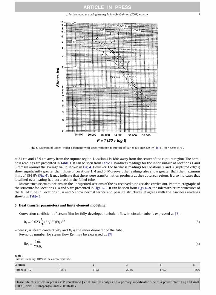
Fig. 5. Diagram of Larsen–Miller parameter with stress variation to rupture of 1Cr–½ Mo steel (ASTM) [6] (1 ksi = 6.895 MPa).
J. Purbolaksono et al. / Engineering Failure Analysis xxx (2009) xxx–xxx 5
ARTICLE IN PRESS
at 21 cm and 18.5 cm away from the rupture region. Location 4 is 180� away from the center of the rupture region. The hard-ness readings are presented in Table 1. It can be seen from Table 1, hardness readings for the inner surface of Locations 1 and5 remain around the average value shown in Fig. 4. However, the hardness readings for Locations 2 and 3 (ruptured edges)show significantly greater than those of Locations 1, 4 and 5. Moreover, the readings also show greater than the maximumlimit of 184 HV (Fig. 4). It may indicate that there were transformation products at the ruptured regions. It also indicates thatlocalized overheating had occurred in the failed tube.
Microstructure examinations on the unruptured sections of the as-received tube are also carried out. Photomicrographs ofthe structure for Locations 1, 4 and 5 are presented in Figs. 6–8. It can be seen from Figs. 6–8, the microstructure structures ofthe failed tube in Locations 1, 4 and 5 show normal ferrite and pearlite structures. It agrees with the hardness readingsshown in Table 1.
5. Heat transfer parameters and finite element modeling
Convection coefficient of steam film for fully developed turbulent flow in circular tube is expressed as [7]:
Table 1Hardne
Locatio
Hardne
Please(2009
hs ¼ 0:023ks
DiðResÞ0:8ðPrsÞ0:4 ð3Þ
where ks is steam conductivity and Di is the inner diameter of the tube.Reynolds number for steam flow Res may be expressed as [7]
Res ¼4 ms�
pDilsð4Þ
ss readings (HV) of the as-received tube.
n 1 2 3 4 5
ss (HV) 155.4 215.1 204.5 176.0 156.6
cite this article in press as: Purbolaksono J et al. Failure analysis on a primary superheater tube of a power plant. Eng Fail Anal), doi:10.1016/j.engfailanal.2009.04.017

Fig. 6. Microstructures (magnification of 200�) of the failed tube at Location 1 as indicated in Fig. 3.
6 J. Purbolaksono et al. / Engineering Failure Analysis xxx (2009) xxx–xxx
ARTICLE IN PRESS
where ms�
is mass flow rate of the steam and ls is steam viscosity. Prandtl number for steam flow Prs may be defined as
Please(2009
Prs ¼lsCps
ksð5Þ
in which Cps is specific heat of the steam.A conservative estimated convection coefficient of flue gas hg on outer surface of bare tube in inline and staggered
arrangements is given by [8]
hg ¼ 0:3312kg
DoðRegÞ0:6ðPrgÞ0:33 ð6Þ
where kg is flue gas conductivity and Do is outer diameter of the tube. The Prandtl number for flue gas flow Prg is defined as
Prg ¼lgCpg
kgð7Þ
Fig. 7. Microstructures (magnification of 500�) of the failed tube at Location 4 as indicated in Fig. 3.
cite this article in press as: Purbolaksono J et al. Failure analysis on a primary superheater tube of a power plant. Eng Fail Anal), doi:10.1016/j.engfailanal.2009.04.017

Fig. 8. Microstructures (magnification of 500�) of the failed tube at Location 5 as indicated in Fig. 3.
J. Purbolaksono et al. / Engineering Failure Analysis xxx (2009) xxx–xxx 7
ARTICLE IN PRESS
in which Cpg and kg are specific heat and thermal conductivity of the flue gas, respectively. The corresponding Reynolds num-ber Reg may be expressed as [8]
Please(2009
Reg ¼GD0
12lgð8Þ
where G is gas mass velocity and may be defined as [8]
G ¼ 12Wg
NwLðSt � D0Þð9Þ
in which Wg is gas flow, Nw is number of tube wide, St is transverse pitch and L is the tube length.The finite element simulations are carried out in order to illustrate the phenomena of heat transfer under normal and
abnormal service conditions. The properties of the elements are defined as 2D-axisymmetric solid elements. In the presenceof the oxide scale the model will have two domain areas, i.e. scale and tube metal, as shown in Fig. 9. Data obtained from thevisual inspection for scale thickness and the geometry of the failed tube are used to generate the geometry of the finite ele-ment models. The bulk temperature and convection coefficient hgas of the flue gas are applied on the right edge of the model(Fig. 9). Next, the bulk temperature and convection coefficient hsteam of the steam are applied on the left edge of the model.
Different convective film coefficients due to steam flow inside tube and flue gas flow outside tube would influence thetemperature profile in the tube metal. Four finite element models are made to illustrate the effect of the steam and fluegas flows on the temperature distributions in the tube. In this study material of the oxide scale is treated to be all magnetite(Fe3O4) which has thermal conductivity of 0.592 W/m �C [1]. The primary superheater SA213-T12 has thermal conductivityof 35 W/m �C [1]. Steam temperature of 450 �C is considered in the finite element simulations. Details of parameters for themodels are shown in Table 2. Each model may be described as follows:
– Model A represents tube under normal service.– Model B represents tube having a higher convective coefficient due to concentrated flue gas flow. Massive clinker forma-
tions have obstructed flue gas flow. Eqs. (8) and (9) may be used to explain this phenomenon. Expression of (St � Do) willphysically become small in the presence of clinkers on the outer surface of the tube, and it results in increasing of the gasmass velocity G.
– Model C represents tube having a higher fire-side convective coefficient and a decreased steam-side convective coefficient.Unbalanced distribution of the firing and a localized flue gas flow might impede mass flow of the steam. Eq. (4) shows thatthe steam-side convective coefficient decrease as the mass flow rate of steam decrease.
– Model D is similar to Model C, but the condition is also triggered by the increased temperature of the flue gas.
Temperature distributions of the models obtained from the finite element simulations are presented in Fig. 10. Model A ismade to approximately represent tube under normal service. Increasing of fire-side convective coefficient causes the in-creased temperature in tube metal as indicated by the temperature distribution for Model B. Further increased temperaturein tube metal due impaired mass flow of steam is indicated by temperature distribution of Model C. The worst situation isrepresented by Model D which results in extremely increased temperature in tube metal. However, either of Models B, C andD may cause short-term overheating problems.
cite this article in press as: Purbolaksono J et al. Failure analysis on a primary superheater tube of a power plant. Eng Fail Anal), doi:10.1016/j.engfailanal.2009.04.017

oxidescale tube metal
steam
hot gas
hollowradius
remaining tube metal thickness
initial tube metal thickness
Fig. 9. Model of the primary superheater tube with scale on the inner surface.
Table 2Details of flue gas temperatures and convective coefficients of steam and flue gas for the finite element models.
Model Tgas (�C) hgas (W/m2 �C) hsteam (W/m2 �C)
A 800 120 1000B 800 600 1000C 800 600 800D 850 600 800
8 J. Purbolaksono et al. / Engineering Failure Analysis xxx (2009) xxx–xxx
ARTICLE IN PRESS
6. Discussion
The failure due to creep damage mechanism under the estimated normal operating temperature is not expected, and ithas been confirmed by the conservative creep analysis showing that the tube should fit for operation for next many yearsunder normal service condition. However, creep-fracture mechanisms as described by Jones [2] may be used to explain pos-sibility of the creep mechanism in the failed tube. At higher temperatures and stresses the failed tube will usually show achisel-edge at the burst region. Finding of the visual observation showed that a thin-lipped feature was found at the rupturedregion of the primary superheater tube. Finite element simulations are carried out to support the investigation and to illus-trate the possible phenomena causing failure of the primary superheater tube. Either condition of increasing of fire-side con-vective coefficient and temperature, or decreasing of steam-side convective coefficient as a result of the impaired mass flowof steam, or combination of them may cause a significant increase of the tube metal temperature. Combination of a highoperating steam pressure and an increased temperature would consequently result in creep rupture of the tube due toshort-term overheating. From the hardness measurements on the ruptured region, the readings indicate significantly higherthan those of ferrite and pearlite parts. It shows that the tube had experienced a localized overheating at the time of failure.The temperature at the ruptured region might have gone above 723 �C.
Please cite this article in press as: Purbolaksono J et al. Failure analysis on a primary superheater tube of a power plant. Eng Fail Anal(2009), doi:10.1016/j.engfailanal.2009.04.017

scale/metal interface
3/4 expansion model of 2D-axisymmetric solid
492.939
495.125
497.311
499.498
501.684
503.871
506.057
508.243
510.430
512.616Model A
575.140
581.512
587.885
594.257
600.629
607.001
613.373
619.745
626.117
632.489Model B
593.590
599.440
605.289
611.138
616.988
622.837
628.686
634.535
640.385
646.234Model C
614.103
620.788
627.473
634.158
640.843
647.528
654.213
660.897
667.582
674.267Model D
Fig. 10. Temperature distributions of the models as stated in Table 2.
J. Purbolaksono et al. / Engineering Failure Analysis xxx (2009) xxx–xxx 9
ARTICLE IN PRESS
The failure mechanism is identified due to the short-term overheating as result of the localized flue gas flow followingmassive clinker formations in primary superheater region. Operation of a new type of coal having low ash fusion tempera-ture of 1210 �C which is close to the minimum specification limit of 1200 �C is identified as the main root cause of the failure.Coal blending for firing of coal with low ash fusion temperature should be strongly considered. Appropriate operation alert incase of low ash fusion temperature of coal firing should also be considerably taken.
7. Conclusions
Failure analysis on the SA213-T12 primary superheater tube by visual site inspection, hardness measurements and finiteelement analyses was presented. Hardness measurements on the failed rupture region and some distance away region of theas-received tubes were carried out in order to support in determining the failure mechanism. Finite element simulationswere able to illustrate the phenomena causing failure of the tube. Short-term overheating as result of the localized fluegas flow following massive clinker formations in primary superheater region was considered as the failure mechanism. Oper-ation of a new type of coal having low ash fusion temperature was the main root cause of the failure.
Acknowledgements
The authors wish to thank Kapar Energy Ventures Sdn Bhd Malaysia and Universiti Tenaga Nasional Malaysia for permis-sion of utilizing all the facilities and resources while conducting this study.
Please cite this article in press as: Purbolaksono J et al. Failure analysis on a primary superheater tube of a power plant. Eng Fail Anal(2009), doi:10.1016/j.engfailanal.2009.04.017

10 J. Purbolaksono et al. / Engineering Failure Analysis xxx (2009) xxx–xxx
ARTICLE IN PRESS
References
[1] French David N. Metallurgical failures in fossil fired boilers. New York: A Wiley-Interscience Publication, John Wiley and Sons Inc.; 2000.[2] Jones DRH. Creep failures of overheated boiler, superheater and reformer tubes. Eng Fail Anal 2004;11:873–93.[3] Port Robert D, Herro Harvey M. The NALCO guide to boiler failure analysis. Nalco Chemical Company, McGraw-Hill Inc.; 1991.[4] ANSYS multiphysics version 11.0. Southpointe 275 Technology Drive Canonsburg (PA): ANSYS, Inc.; 2008.[5] Viswanathan R, Foulds JR, Roberts DA. Method for estimating the temperature of reheater and superheater tubes in fossils boilers. In: Proceedings of the
international conference on life extension and assessment, The Hague; 1988.[6] Smith GV. Evaluation of the elevated temperature tensile and creep-rupture properties of ½Cr–½Mo, 1Cr–½Mo, and 11=4Cr–½Mo steels. Philadelphia
(PA): ASTM; 1973.[7] Incropera FP, DeWitt DP. Introduction to heat transfer. 3rd ed. John Wiley; 1996.[8] Ganapathy V. Industrial boilers and heat recovery steam generators: design, applications, and calculations. New York: Marcel Dekker; 2003.
Please cite this article in press as: Purbolaksono J et al. Failure analysis on a primary superheater tube of a power plant. Eng Fail Anal(2009), doi:10.1016/j.engfailanal.2009.04.017


![Sport Utility Vehicle...Rated output1 (kW [HP] at rpm) XXX XXX XXX XXX XXX Acceleration from 0 to 100 km/h (s) XXX XXX XXX XXX XXX Top speed (km/h) XXX 3XXX XXX 3XXX XXX3 Fuel consumption4](https://static.fdocuments.in/doc/165x107/5e9ad03bae36bf4b5c045c78/sport-utility-vehicle-rated-output1-kw-hp-at-rpm-xxx-xxx-xxx-xxx-xxx-acceleration.jpg)