Engineering Failure Analysis -...
11
Failure analysis on abnormal wall thinning of heat-transfer titanium tubes of condensers in nuclear power plant Part II: Erosion and cavitation corrosion Fei-Jun Chen, Cheng Yao, Zhen-Guo Yang ⇑ Department of Materials Science, Fudan University, Shanghai 200433, PR China article info Article history: Received 24 March 2013 Accepted 19 November 2013 Available online 4 December 2013 Keywords: Titanium tube Wall thinning Failure analysis Erosion Cavitation corrosion abstract In Part I of the failure analysis on abnormal wall thinning of heat-transfer titanium tubes used in condensers in nuclear power plant, we analyzed the causes and mechanisms of abnormal thinning that commonly happened at the contact part between the tubes and the support plates. This kind of failure was the mainstream failure type in our case and the main causes were found to be eccentric contact wear and three-body contact wear rooted in processing defect of internal borings, corrosion products deposit and sagging, and foreign particles. However, there were still some individual failure tubes with different failure sites and modes and were located under the bypass pipes at the shoulder of the tube tower instead of in its lower part, obviously telling another failure story. In Part II of the failure analysis, material analysis, metallographic examination, mechanical performance tests, macro- and microstructure analysis and composition analysis were conducted. The failure causes were found to be erosion and cavitation corrosion and the synergetic effect of them. Finally, corresponding countermeasures were suggested. Ó 2013 Elsevier Ltd. All rights reserved. 1. Introduction Since nuclear power was utilized, safety concerns have never stopped to bother us. From the disaster of Chernobyl in Russia decades ago, to the nuclear leak in Fukushima in the last two years, historical lessons written in blood have taught us that every detail in a nuclear power station is of critical importance and not a single tiniest potential peril can be ignored. The heat-transfer titanium tubes in condensers of the two 700 MW CANDU units in China – the first and only two pres- surized heavy water reactor (PHWR) units in the country – have encountered abnormal tube wall thinning. With a design life of 40 years, the condensers were forced to temporarily stop operation after only 8 years in service because unexpected wall thinning problems were found on the heat-transfer titanium tubes, bringing about heavy economic loss and potential safety threat. Our team was asked to conduct failure analysis of the tubes. The tubes are made of industrial pure titanium in correspondence to Chinese brand TA1, with the length of 17370 mm, and specifications of 25.4 mm 0.5 mm (outside diameter wall thickness). All these specifications have also been mentioned in Part I [1] of the failure analysis. Among the dozens of tube samples we got, most of them presented similar failure modes at similar positions. After detailed analysis by various techniques, we primarily ascribed most of the failure cases to eccentric contact wear and three-body contact wear rooted in processing defect of internal borings, corrosion products deposit and sagging, and foreign particles, discussed in Part I [1] of the failure analysis. However, we still found another kind of failure case with distinct appearance and failure positions. When we conducted inspection inside the condenser, we discovered the bypass pipes, 1350-6307/$ - see front matter Ó 2013 Elsevier Ltd. All rights reserved. http://dx.doi.org/10.1016/j.engfailanal.2013.11.002 ⇑ Corresponding author. Tel.: +86 21 65642523; fax: +86 21 65103056. E-mail address: [email protected] (Z.-G. Yang). Engineering Failure Analysis 37 (2014) 42–52 Contents lists available at ScienceDirect Engineering Failure Analysis journal homepage: www.elsevier.com/locate/engfailanal
Transcript of Engineering Failure Analysis -...
Engineering Failure Analysis 37 (2014) 42–52
Contents lists available at ScienceDirect
Engineering Failure Analysis
journal homepage: www.elsevier .com/locate /engfai lanal
Failure analysis on abnormal wall thinning of heat-transfertitanium tubes of condensers in nuclear power plantPart II: Erosion and cavitation corrosion
1350-6307/$ - see front matter � 2013 Elsevier Ltd. All rights reserved.http://dx.doi.org/10.1016/j.engfailanal.2013.11.002
⇑ Corresponding author. Tel.: +86 21 65642523; fax: +86 21 65103056.E-mail address: [email protected] (Z.-G. Yang).
Fei-Jun Chen, Cheng Yao, Zhen-Guo Yang ⇑Department of Materials Science, Fudan University, Shanghai 200433, PR China
a r t i c l e i n f o
Article history:Received 24 March 2013Accepted 19 November 2013Available online 4 December 2013
Keywords:Titanium tubeWall thinningFailure analysisErosionCavitation corrosion
a b s t r a c t
In Part I of the failure analysis on abnormal wall thinning of heat-transfer titanium tubesused in condensers in nuclear power plant, we analyzed the causes and mechanisms ofabnormal thinning that commonly happened at the contact part between the tubes andthe support plates. This kind of failure was the mainstream failure type in our case andthe main causes were found to be eccentric contact wear and three-body contact wearrooted in processing defect of internal borings, corrosion products deposit and sagging,and foreign particles. However, there were still some individual failure tubes with differentfailure sites and modes and were located under the bypass pipes at the shoulder of the tubetower instead of in its lower part, obviously telling another failure story. In Part II of thefailure analysis, material analysis, metallographic examination, mechanical performancetests, macro- and microstructure analysis and composition analysis were conducted. Thefailure causes were found to be erosion and cavitation corrosion and the synergetic effectof them. Finally, corresponding countermeasures were suggested.
� 2013 Elsevier Ltd. All rights reserved.
1. Introduction
Since nuclear power was utilized, safety concerns have never stopped to bother us. From the disaster of Chernobyl inRussia decades ago, to the nuclear leak in Fukushima in the last two years, historical lessons written in blood have taughtus that every detail in a nuclear power station is of critical importance and not a single tiniest potential peril can be ignored.
The heat-transfer titanium tubes in condensers of the two 700 MW CANDU units in China – the first and only two pres-surized heavy water reactor (PHWR) units in the country – have encountered abnormal tube wall thinning. With a design lifeof 40 years, the condensers were forced to temporarily stop operation after only 8 years in service because unexpected wallthinning problems were found on the heat-transfer titanium tubes, bringing about heavy economic loss and potential safetythreat. Our team was asked to conduct failure analysis of the tubes. The tubes are made of industrial pure titanium incorrespondence to Chinese brand TA1, with the length of 17370 mm, and specifications of 25.4 mm � 0.5 mm (outsidediameter �wall thickness). All these specifications have also been mentioned in Part I [1] of the failure analysis.
Among the dozens of tube samples we got, most of them presented similar failure modes at similar positions. Afterdetailed analysis by various techniques, we primarily ascribed most of the failure cases to eccentric contact wear andthree-body contact wear rooted in processing defect of internal borings, corrosion products deposit and sagging, and foreignparticles, discussed in Part I [1] of the failure analysis. However, we still found another kind of failure case with distinctappearance and failure positions. When we conducted inspection inside the condenser, we discovered the bypass pipes,
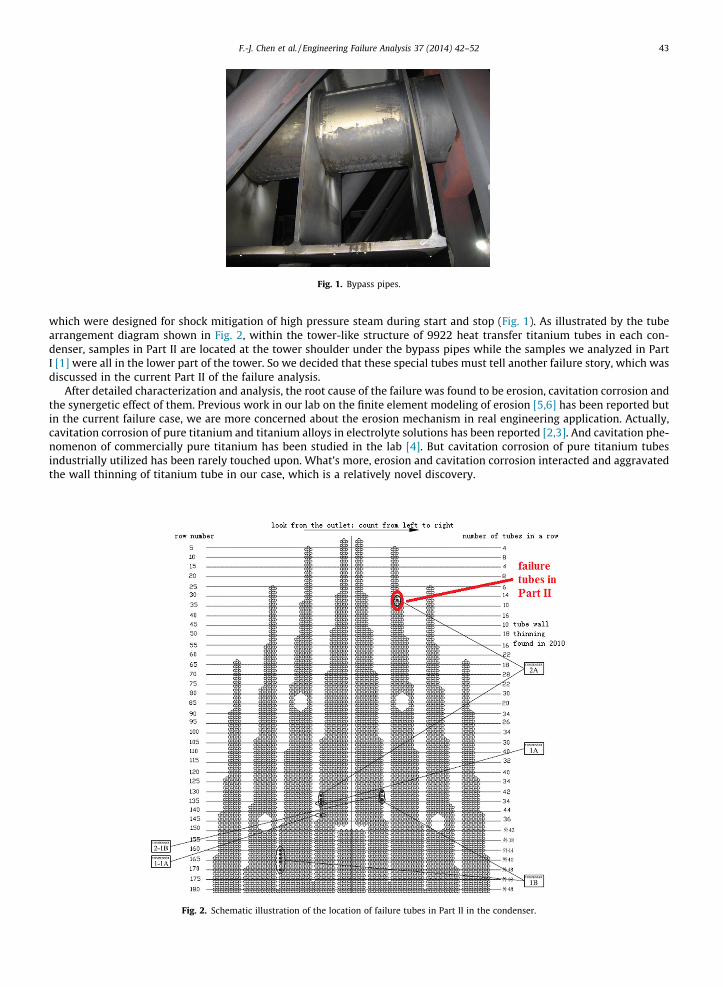
Fig. 1. Bypass pipes.
F.-J. Chen et al. / Engineering Failure Analysis 37 (2014) 42–52 43
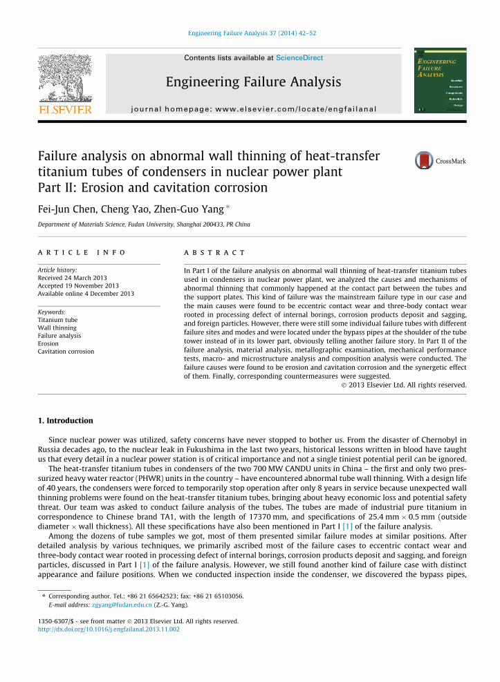
which were designed for shock mitigation of high pressure steam during start and stop (Fig. 1). As illustrated by the tubearrangement diagram shown in Fig. 2, within the tower-like structure of 9922 heat transfer titanium tubes in each con-denser, samples in Part II are located at the tower shoulder under the bypass pipes while the samples we analyzed in PartI [1] were all in the lower part of the tower. So we decided that these special tubes must tell another failure story, which wasdiscussed in the current Part II of the failure analysis.
After detailed characterization and analysis, the root cause of the failure was found to be erosion, cavitation corrosion andthe synergetic effect of them. Previous work in our lab on the finite element modeling of erosion [5,6] has been reported butin the current failure case, we are more concerned about the erosion mechanism in real engineering application. Actually,cavitation corrosion of pure titanium and titanium alloys in electrolyte solutions has been reported [2,3]. And cavitation phe-nomenon of commercially pure titanium has been studied in the lab [4]. But cavitation corrosion of pure titanium tubesindustrially utilized has been rarely touched upon. What’s more, erosion and cavitation corrosion interacted and aggravatedthe wall thinning of titanium tube in our case, which is a relatively novel discovery.
Fig. 2. Schematic illustration of the location of failure tubes in Part II in the condenser.
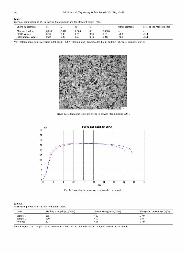
Table 1Chemical composition of TA1 in-service titanium tube and the standard values (wt%).
Chemical element Fe C N O H Other elements Total of the rest elements
Measured values 0.058 0.012 0.004 0.1 0.0026 – –SB338 values 0.30 0.08 0.03 0.25 0.15 60.1 60.4International values 0.20 0.08 0.03 0.18 0.015 60.1 60.4
Note: International values are from GB/T 3620.1-2007 ‘‘titanium and titanium alloy brand and their chemical composition’’ [8].
Fig. 3. Metallographic structure of one in-service titanium tube 200�.
Fig. 4. Force–displacement curve of tensile test sample.
Table 2Mechanical properties of in-service titanium tubes.
Item Yielding strength (r0.2/MPa) Tensile strength (rb/MPa) Elongation percentage (d5/%)
Sample 1 365 440 37.0Sample 2 290 450 38.8Average 327 445 37.9
Note: Sample 1 and sample 2 were taken from tubes 2A032012-1 and 2A032012-5, 6 in condenser 2A of unit 1.
44 F.-J. Chen et al. / Engineering Failure Analysis 37 (2014) 42–52
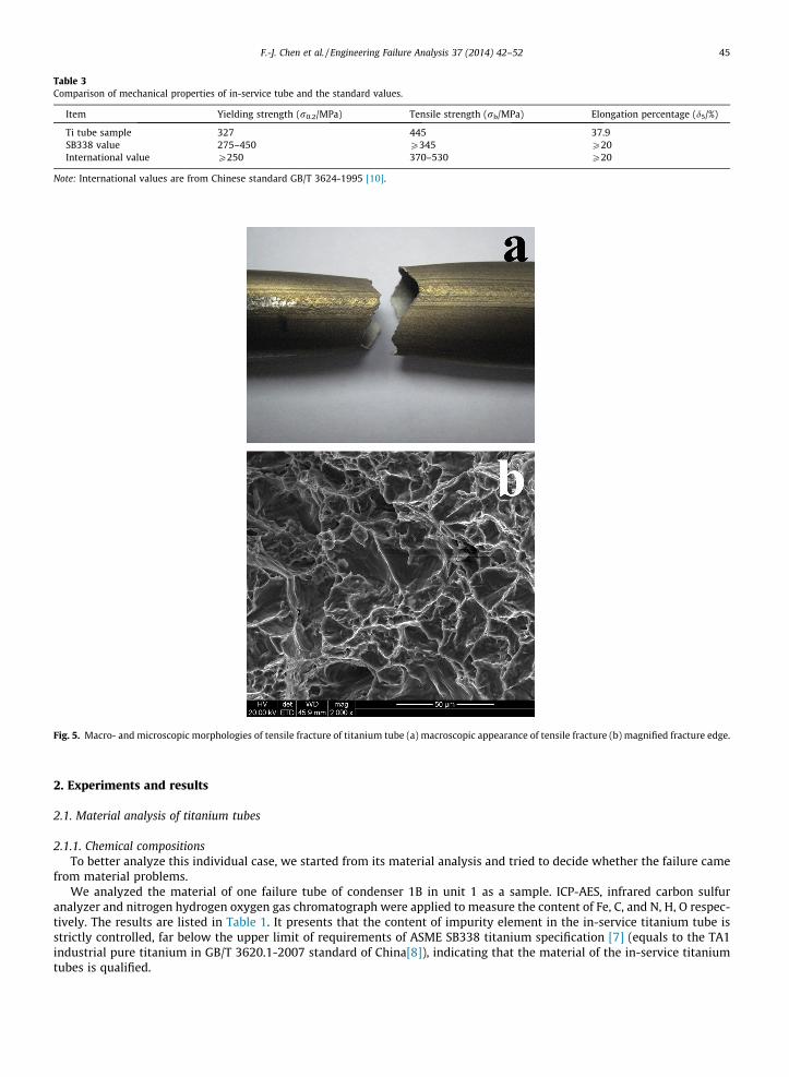
Table 3Comparison of mechanical properties of in-service tube and the standard values.
Item Yielding strength (r0.2/MPa) Tensile strength (rb/MPa) Elongation percentage (d5/%)
Ti tube sample 327 445 37.9SB338 value 275–450 P345 P20International value P250 370–530 P20
Note: International values are from Chinese standard GB/T 3624-1995 [10].
Fig. 5. Macro- and microscopic morphologies of tensile fracture of titanium tube (a) macroscopic appearance of tensile fracture (b) magnified fracture edge.
F.-J. Chen et al. / Engineering Failure Analysis 37 (2014) 42–52 45
2. Experiments and results
2.1. Material analysis of titanium tubes
2.1.1. Chemical compositionsTo better analyze this individual case, we started from its material analysis and tried to decide whether the failure came
from material problems.We analyzed the material of one failure tube of condenser 1B in unit 1 as a sample. ICP-AES, infrared carbon sulfur
analyzer and nitrogen hydrogen oxygen gas chromatograph were applied to measure the content of Fe, C, and N, H, O respec-tively. The results are listed in Table 1. It presents that the content of impurity element in the in-service titanium tube isstrictly controlled, far below the upper limit of requirements of ASME SB338 titanium specification [7] (equals to the TA1industrial pure titanium in GB/T 3620.1-2007 standard of China[8]), indicating that the material of the in-service titaniumtubes is qualified.
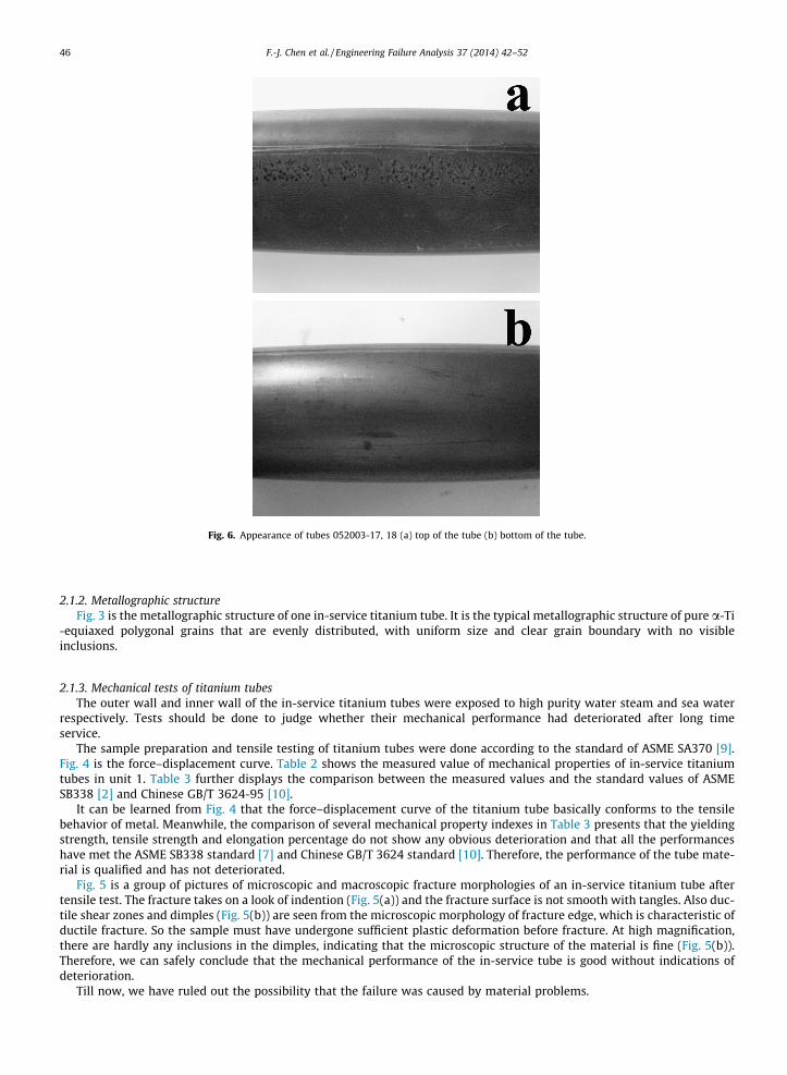
Fig. 6. Appearance of tubes 052003-17, 18 (a) top of the tube (b) bottom of the tube.
46 F.-J. Chen et al. / Engineering Failure Analysis 37 (2014) 42–52
2.1.2. Metallographic structureFig. 3 is the metallographic structure of one in-service titanium tube. It is the typical metallographic structure of pure a-Ti
-equiaxed polygonal grains that are evenly distributed, with uniform size and clear grain boundary with no visibleinclusions.
2.1.3. Mechanical tests of titanium tubesThe outer wall and inner wall of the in-service titanium tubes were exposed to high purity water steam and sea water
respectively. Tests should be done to judge whether their mechanical performance had deteriorated after long timeservice.
The sample preparation and tensile testing of titanium tubes were done according to the standard of ASME SA370 [9].Fig. 4 is the force–displacement curve. Table 2 shows the measured value of mechanical properties of in-service titaniumtubes in unit 1. Table 3 further displays the comparison between the measured values and the standard values of ASMESB338 [2] and Chinese GB/T 3624-95 [10].
It can be learned from Fig. 4 that the force–displacement curve of the titanium tube basically conforms to the tensilebehavior of metal. Meanwhile, the comparison of several mechanical property indexes in Table 3 presents that the yieldingstrength, tensile strength and elongation percentage do not show any obvious deterioration and that all the performanceshave met the ASME SB338 standard [7] and Chinese GB/T 3624 standard [10]. Therefore, the performance of the tube mate-rial is qualified and has not deteriorated.
Fig. 5 is a group of pictures of microscopic and macroscopic fracture morphologies of an in-service titanium tube aftertensile test. The fracture takes on a look of indention (Fig. 5(a)) and the fracture surface is not smooth with tangles. Also duc-tile shear zones and dimples (Fig. 5(b)) are seen from the microscopic morphology of fracture edge, which is characteristic ofductile fracture. So the sample must have undergone sufficient plastic deformation before fracture. At high magnification,there are hardly any inclusions in the dimples, indicating that the microscopic structure of the material is fine (Fig. 5(b)).Therefore, we can safely conclude that the mechanical performance of the in-service tube is good without indications ofdeterioration.
Till now, we have ruled out the possibility that the failure was caused by material problems.
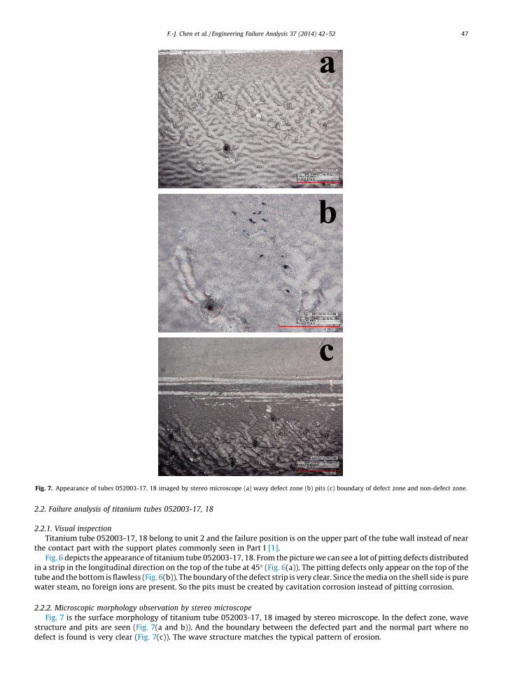
Fig. 7. Appearance of tubes 052003-17, 18 imaged by stereo microscope (a) wavy defect zone (b) pits (c) boundary of defect zone and non-defect zone.
F.-J. Chen et al. / Engineering Failure Analysis 37 (2014) 42–52 47
2.2. Failure analysis of titanium tubes 052003-17, 18
2.2.1. Visual inspectionTitanium tube 052003-17, 18 belong to unit 2 and the failure position is on the upper part of the tube wall instead of near
the contact part with the support plates commonly seen in Part I [1].Fig. 6 depicts the appearance of titanium tube 052003-17, 18. From the picture we can see a lot of pitting defects distributed
in a strip in the longitudinal direction on the top of the tube at 45� (Fig. 6(a)). The pitting defects only appear on the top of thetube and the bottom is flawless (Fig. 6(b)). The boundary of the defect strip is very clear. Since the media on the shell side is purewater steam, no foreign ions are present. So the pits must be created by cavitation corrosion instead of pitting corrosion.
2.2.2. Microscopic morphology observation by stereo microscopeFig. 7 is the surface morphology of titanium tube 052003-17, 18 imaged by stereo microscope. In the defect zone, wave
structure and pits are seen (Fig. 7(a and b)). And the boundary between the defected part and the normal part where nodefect is found is very clear (Fig. 7(c)). The wave structure matches the typical pattern of erosion.
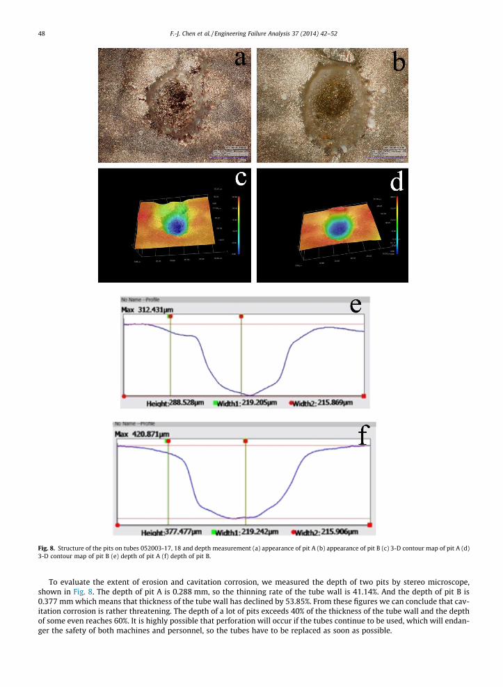
Fig. 8. Structure of the pits on tubes 052003-17, 18 and depth measurement (a) appearance of pit A (b) appearance of pit B (c) 3-D contour map of pit A (d)3-D contour map of pit B (e) depth of pit A (f) depth of pit B.
48 F.-J. Chen et al. / Engineering Failure Analysis 37 (2014) 42–52
To evaluate the extent of erosion and cavitation corrosion, we measured the depth of two pits by stereo microscope,shown in Fig. 8. The depth of pit A is 0.288 mm, so the thinning rate of the tube wall is 41.14%. And the depth of pit B is0.377 mm which means that thickness of the tube wall has declined by 53.85%. From these figures we can conclude that cav-itation corrosion is rather threatening. The depth of a lot of pits exceeds 40% of the thickness of the tube wall and the depthof some even reaches 60%. It is highly possible that perforation will occur if the tubes continue to be used, which will endan-ger the safety of both machines and personnel, so the tubes have to be replaced as soon as possible.
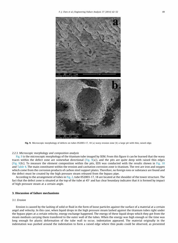
Fig. 9. Microscopic morphology of defects on tubes 052003-17, 18 (a) wavy erosion zone (b) a large pit with thin, raised edge.
F.-J. Chen et al. / Engineering Failure Analysis 37 (2014) 42–52 49
2.2.3. Microscopic morphology and composition analysisFig. 9 is the microscopic morphology of the titanium tube imaged by SEM. From this figure it can be learned that the wavy
traces within the defect zone are somewhat directional (Fig. 9(a)), and the pits are quite deep with raised thin edges(Fig. 9(b)). To measure the element composition within the pits, EDS was conducted with the results shown in Fig. 10and Table 4. The main constituent within the erosion and cavitation corrosion zone is titanium. The rest are iron and oxygenwhich come from the corrosion products of carbon steel support plates. Therefore, no foreign ions or substance are found andthe defect must be created by the high pressure steam released from the bypass pipe.
According to the arrangement of tubes in Fig. 2, tube 052003-17, 18 are located at the shoulder of the tower structure. Thefact that the defect zone is situated at the top of the tube at 45� and has clear boundary indicates that it is formed by impactof high pressure steam at a certain angle.
3. Discussion of failure mechanisms
3.1. Erosion
Erosion is caused by the lashing of solid or fluid in the form of loose particles against the surface of a material at a certainangel and velocity. In this case, when liquid drops in the high pressure steam lashed against the titanium tubes right underthe bypass pipes at a certain velocity, energy exchange happened. The energy of these liquid drops which they got from thesteam medium carrying them transfered to the outer wall of the tubes. When the energy was high enough or the time waslong enough for plastic deformation of the tube wall to occur, indentation appeared. The material originally in theindentation was pushed around the indentation to form a raised edge where thin peaks could be observed, as presented
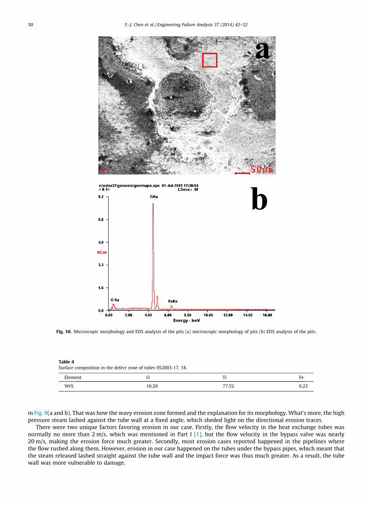
Fig. 10. Microscopic morphology and EDS analysis of the pits (a) microscopic morphology of pits (b) EDS analysis of the pits.
Table 4Surface composition in the defect zone of tubes 052003-17, 18.
Element O Ti Fe
Wt% 16.26 77.52 6.22
50 F.-J. Chen et al. / Engineering Failure Analysis 37 (2014) 42–52
in Fig. 9(a and b). That was how the wavy erosion zone formed and the explanation for its morphology. What’s more, the highpressure steam lashed against the tube wall at a fixed angle, which sheded light on the directional erosion traces.
There were two unique factors favoring erosion in our case. Firstly, the flow velocity in the heat exchange tubes wasnormally no more than 2 m/s, which was mentioned in Part I [1], but the flow velocity in the bypass valve was nearly20 m/s, making the erosion force much greater. Secondly, most erosion cases reported happened in the pipelines wherethe flow rushed along them. However, erosion in our case happened on the tubes under the bypass pipes, which meant thatthe steam released lashed straight against the tube wall and the impact force was thus much greater. As a result, the tubewall was more vulnerable to damage.
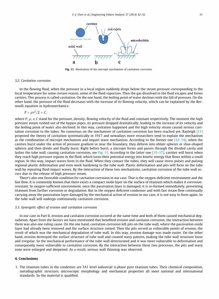
Fig. 11. Illustration of the microjet mechanism of cavitation corrosion.
F.-J. Chen et al. / Engineering Failure Analysis 37 (2014) 42–52 51
3.2. Cavitation corrosion
In the flowing fluid, when the pressure in a local region suddenly drops below the steam pressure corresponding to thelocal temperature for some certain reason, some of the fluid vaporizes. Then the gas dissolved in the fluid escapes and formscavities. This process is called cavitation. On the one hand, the boiling point of water declines with the fall of pressure. On theother hand, the pressure of the fluid decreases with the increase of its flowing velocity, which can be explained by the Ber-noulli equation in hydromechanics:
P þ qm2=2 ¼ C;
where P, q, v, C stand for the pressure, density, flowing velocity of the fluid and constant respectively. The moment the highpressure steam rushed out of the bypass pipes, its pressure dropped dramatically, leading to the increase of its velocity andthe boiling point of water also declined. In this way, cavitation happened and the high velocity steam caused serious cavi-tation corrosion to the tubes. No consensus on the mechanism of cavitation corrosion has been reached yet. Rayleigh [11]proposed the theory of cavitation systematically in 1917 and nowadays more researchers tend to explain the mechanismas the combination of microjet mechanism and impact wave mechanism. According to the former one [12–14], when thecavities burst under the action of pressure gradient or near the boundary, they deform into oblate spheres or shoe-shapedspheres and then divide and finally burst. Right before burst, a microjet forms and passes through the divided cavity andlashes the tube wall, causing cavitation corrosion, see Fig. 11. According to the latter one [15–17], cavities will burst whenthey reach high pressure regions in the fluid, which turns their potential energy into kinetic energy that flows within a smallregion. In this way, impact waves form in the fluid. When they contact the tubes, they will cause stress pulses and pulsingregional plastic deformation and even work hardening to the tube wall. Plastic deformation and pits will form on the tubewall by repeating fluid impact waves. By the interaction of these two mechanisms, cavitation corrosion of the tube wall oc-curs due to the release of high pressure steam.
There’s also one favorable condition for cavitation corrosion in our case. That is the oxygen-deficient environment and thefast flow. It is commonly known that there exists a compact oxide layer on the surface of titanium which makes it corrosion-resistant. In oxygen-sufficient environment, once the passivation layer is damaged, it is re-formed immediately, preventingtitanium from further corrosion or degradation. But in the oxygen deficient condenser and with fast steam flow continuallycarrying away the passivation layer damaged by the mechanical action of erosion in our case, it is not easy to form again. Sothe tube wall will undergo continuously cavitation corrosion.
3.3. Synergetic effect of erosion and cavitation corrosion
In our case in Part II, erosion and cavitaion corrosion occured at the same time and both of them caused mechanical deg-radation. Apart from the factors we have mentioned that benefited erosion and cavitaion corrosion, the interaction betweenthem was also one ruling cause. On the one hand, cavitation corrosion left pits on the tube wall, where the passivation oxidelayer had already been removed and the surface structure ruined. Then the pits served as vulnerable points of erosion, theresult of which was the mechanical degradation of tube wall. In this way, erosion damage was made easier. On the otherhand, erosion destroyed the surface structure of tube wall and created wavy pattern, making the tube wall structure looseand irregular. So the mechanical performance of the tube wall deteriorated and it was more vulnerable to deformation andconsequently more vulnerable to cavitation corrosion. By the interaction between these two processes, the pits and wavyzone were enlarged and deepened. As a result, serious wall thinning was observed.
4. Conclusions
1. The titanium tubes in the condenser are TA1 level industrial a-phase pure titanium tubes. Their chemical composition,metallographic structure, microscopic morphology and mechanical properties all meet national and internationalstandards. So the material is qualified.
52 F.-J. Chen et al. / Engineering Failure Analysis 37 (2014) 42–52
2. The wall thinning failure of the sample in this paper was caused by the high pressure steam released through bypasspipes. The mechanism was erosion and cavitation corrosion, and the synergetic effect of them.
5. Suggestions
Control the pressure and velocity of steam released from the bypass pipes within a certain range and keep monitoring thewall thickness and surface conditions of the tubes under them. Once wall thinning reaches a certain extent, the tubes have tobe replaced.
Acknowledgements
This work was cooperated with Third Qinshan Nuclear Power Co. Ltd. (TQNPC) and was supported by Shanghai LeadingAcademic Discipline Project (Project Number: B113).
References
[1] Chen Fei-Jun, Yao Cheng, Yang Zhen-Guo. Failure analysis on abnormal wall thinning of heat-transfer titanium tubes of condensers in nuclear powerplant Part I: Corrosion and wear. Eng Fail Anal 2014;37:29–41.
[2] Mochizuki Hiromi, Yokota Motohiro, Hattori Shuji. Effects of materials and solution temperatures on cavitation erosion of pure titanium and titaniumalloy in seawater. Wear 2007;262:522–8.
[3] Neville A, McDougall BAB. Erosion and cavitation corrosion of titanium and its alloys. Wear 2001;250:726–35.[4] Tan MJ, Zhu XJ, Thiruvarudchelvan S. Cavitation phenomenon of commercially pure titanium. J Mater Process Tech 2007;191:202–5.[5] Wang Yu-Fei, Yang Zhen-Guo. A coupled finite element and meshfree analysis of erosive wear. Tribol Int 2009;42(2):373–7.[6] Wang Yu-Fei, Yang Zhen-Guo. Finite element model of erosive wear on ductile and brittle materials. Wear 2008;265(5):871–8.[7] ASME SB-338-2007. Specification for seamless and welded titanium and titanium alloy tubes for condensers and heat exchangers.[8] GB/T 3620.1-2007. Titanium and titanium alloy brand and chemical composition.[9] ASME SA370. Standard test methods and definitions for mechanical testing of steel products.
[10] GB/T 3624-1995. Titanium and titanium alloy seamless tubes.[11] Rayleigh L. On the pressure developed in a liquid during the collapse of a spherical cavity. Philos Mag 1917;34:94–8.[12] Gregorcic P, Petkovsek R, Mozina J. Investigation of a cavitation bubble between a rigid boundary and a free surface. J Appl Phys
2007;102:094904(1)–4(8).[13] Singer BG, Harvey SJ. Cavitation damage studies using plasticine. Wear 1979;2l(7):409–16.[14] Preece CM, Brunton JH. A comparison of liquid impact erosion and cavitation erosion. Wear 1980;60(2):269–84.[15] Okada T, Hammitt FG. Cavitation erosion in vibratory and venture facilities. Wear 1981;60(1):55–69.[16] Matsumoto Y. Influence of homogeneous condensation inside a small gas bubble on its pressure response. J Fluid Eng 1985;107(2):281–6.[17] Phlipp A, Lauterborn W. Cavitation erosion by single laser-produced bubbles. J Fluid Mech 1998;36l:75–116.