Engineering Failure Analysis - CORE · 1.3. Failed components A number of critical components in...
17
Potential hazards from undetected corrosion in complex equipment: A case study of the destructive separation of an offshore heat exchanger R. Parrott ⇑ Health and Safety Laboratory, Harpur Hill, Buxton, Derbyshire SK17 9JN, UK article info Article history: Received 26 March 2014 Received in revised form 27 May 2014 Accepted 10 June 2014 Available online 20 June 2014 Keywords: Heat exchanger failures Galvanic corrosion Hydrogen Titanium abstract This paper describes hazards from undetected corrosion in complex equipment using find- ings from a collaborative forensic investigation into the destructive separation of a heat exchanger on an offshore gas storage platform. The heat exchanger had been in service for 24 years. The heat exchanger was a conventional shell-and-tube type with both the tubes and shell being manufactured from titanium. However the bonnet and tube sheet were manufactured from carbon steel. The seawater side of the carbon steel tube sheet had been protected from corrosion by titanium cladding. The investigation revealed localised corrosion of the carbon steel tube sheet in areas exposed to acidic condensate containing hydrogen sulphide. Corrosion was galvanic in nat- ure and had occurred where, by design; the carbon steel–titanium interface was exposed. The results showed that hydrogen, generated cathodically by the galvanic corrosion, had formed titanium hydride in the interfacial region of the titanium cladding. The evidence indicated that the separation of the tube bundle and shell from the bonnet was probablyinitiatedwhena largeareaof the claddingbondinterface failedsuddenlyduetohydride formation. The final destructive separation of the tube bundle can be explained by the deforma- tion of the cladding after complete failure of the bonded interface with the tube sheet. This article and the forensic investigation were funded by the Health and Safety Executive (HSE). Its contents, including any opinions and/or conclusions expressed, are those of the author alone and do not necessarily reflect HSE policy. The UK Health and Safety Executive funded this paper to draw attention to the potential hazards that can arise from undetected corrosion in complex equipment. Crown Copyright Ó 2014 Published by Elsevier Ltd. This is an open access article under the Open Government Licence (OGL) (http://www.nationalarchives.gov.uk/doc/open-govern- ment-licence/version/2/). 1. Introduction 1.1. Background A horizontal shell-and-tube heat exchanger failed on an offshore storage platform. The tube bundle and shell separated completely from the bonnet with considerable force and approximately 10 tonnes of hydrocarbon gas was released [1]. http://dx.doi.org/10.1016/j.engfailanal.2014.06.002 1350-6307/Crown Copyright Ó 2014 Published by Elsevier Ltd. This is an open access article under the Open Government Licence (OGL) (http:// www.nationalarchives.gov.uk/doc/open-government-licence/version/2/). ⇑ Tel.: +44 1298218228; fax: +44 1298218270. E-mail address: [email protected] Engineering Failure Analysis 44 (2014) 424–440 Contents lists available at ScienceDirect Engineering Failure Analysis journal homepage: www.elsevier.com/locate/engfailanal
Transcript of Engineering Failure Analysis - CORE · 1.3. Failed components A number of critical components in...
Engineering Failure Analysis 44 (2014) 424–440
Contents lists available at ScienceDirect
Engineering Failure Analysis
journal homepage: www.elsevier .com/locate /engfai lanal
Potential hazards from undetected corrosion in complexequipment: A case study of the destructive separation of anoffshore heat exchanger
http://dx.doi.org/10.1016/j.engfailanal.2014.06.0021350-6307/Crown Copyright � 2014 Published by Elsevier Ltd. This is an open access article under the Open Government Licence (OGL)www.nationalarchives.gov.uk/doc/open-government-licence/version/2/).
⇑ Tel.: +44 1298218228; fax: +44 1298218270.E-mail address: [email protected]
R. Parrott ⇑Health and Safety Laboratory, Harpur Hill, Buxton, Derbyshire SK17 9JN, UK
a r t i c l e i n f o
Article history:Received 26 March 2014Received in revised form 27 May 2014Accepted 10 June 2014Available online 20 June 2014
Keywords:Heat exchanger failuresGalvanic corrosionHydrogenTitanium
a b s t r a c t
This paper describes hazards from undetected corrosion in complex equipment using find-ings from a collaborative forensic investigation into the destructive separation of a heatexchanger on an offshore gas storage platform. The heat exchanger had been in servicefor 24 years. The heat exchanger was a conventional shell-and-tube type with both thetubes and shell being manufactured from titanium. However the bonnet and tube sheetwere manufactured from carbon steel. The seawater side of the carbon steel tube sheethad been protected from corrosion by titanium cladding.
The investigation revealed localised corrosion of the carbon steel tube sheet in areasexposed to acidic condensate containing hydrogen sulphide. Corrosion was galvanic in nat-ure and had occurred where, by design; the carbon steel–titanium interface was exposed.The results showed that hydrogen, generated cathodically by the galvanic corrosion, hadformed titanium hydride in the interfacial region of the titanium cladding.
The evidence indicated that the separation of the tube bundle and shell from the bonnet wasprobablyinitiatedwhenalargeareaofthecladdingbondinterfacefailedsuddenlyduetohydrideformation. The final destructive separation of the tube bundle can be explained by the deforma-tion of the cladding after complete failure of the bonded interface with the tube sheet.
This article and the forensic investigation were funded by the Health and Safety Executive(HSE). Its contents, including any opinions and/or conclusions expressed, are those of theauthor alone and do not necessarily reflect HSE policy. The UK Health and Safety Executivefunded this paper to draw attention to the potential hazards that can arise from undetectedcorrosion in complex equipment.Crown Copyright � 2014 Published by Elsevier Ltd. This is an open access article under theOpen Government Licence (OGL) (http://www.nationalarchives.gov.uk/doc/open-govern-
ment-licence/version/2/).
1. Introduction
1.1. Background
A horizontal shell-and-tube heat exchanger failed on an offshore storage platform. The tube bundle and shell separatedcompletely from the bonnet with considerable force and approximately 10 tonnes of hydrocarbon gas was released [1].
(http://
R. Parrott / Engineering Failure Analysis 44 (2014) 424–440 425
Adjacent equipment on the platform was damaged by the force generated from the separation of the heat exchanger. Therewas further extensive damage in the fire and explosion that ensued when the gas cloud ignited. Personnel on the platformwere evacuated successfully and there were only minor injuries.
The Health and Safety Laboratory (HSL) carried out a forensic metallurgical investigation for the Health and Safety Exec-utive (HSE) to determine how the heat exchanger had failed. This investigation was overseen by a collaboration of technicalexperts from HSL, HSE and the platform operator with industrial experts from two independent organisations. The OffshoreDivision of the HSE issued a Safety Alert [2] to make the results of the investigation available to other users.
The original function of the heat exchanger was to cool hydrocarbon gas from wells before pumping on-shore. In recentyears, however, the heat exchanger had been used on a cyclic basis, cooling gas being pumped off shore into the formationsfor storage during summer months and cooling gas extracted from the formations during winter months. It was reportedthat gas pumped for storage was pre-dried before passing through the heat exchanger but gas extracted from the formationscontained moisture that was intended to condense in the heat exchanger.
1.2. Design aspects
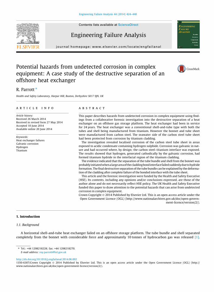
The heat exchanger was a conventional shell-and-tube bundle design that was manufactured in 1983 for a gas pressure of100 bar (1450 psig) in the tubes and a shell seawater pressure of 10.3 bar (150 psig). At the time of failure, the gas pressurewas 90 bar (1300 psig) and the cooling water pressure was 10 bar (145 psig). The heat exchanger was approximately 9 mlong overall with a shell diameter of 1 m and a bundle of 1130 tubes, each 6.5 m long. The tube specification was 3=4 in.OD, 16 BWG tubing to ASTM/ASME SM338 Grade 3 titanium. Fig. 1 shows the main components schematically.
The tube bundle and shell were manufactured from titanium. The bonnet and tube sheet were manufactured from carbon steel(CS) but the seawater side of the tube sheet had been clad with 13 mm thick titanium. The cladding had been applied by explosivebonding and every tube-to-cladding joint was circumferentially welded into a recess in the titanium cladding sheet, Fig. 2.
The heat exchanger was designed to use titanium for seawater contact and a combination of titanium and carbon steel forsurfaces in contact with the hydrocarbon gas and condensate. The interface between the titanium and carbon steel surfaceson the gas side was inside the holes of the tube sheet. A significant design feature, therefore, was the exposure of thetitanium–carbon steel interface to the high pressure gas stream and condensate.
Tube–tube sheet joints are a critical feature of heat exchanger design. A number of joint designs can be used which rangefrom welded joints to tubes that are mechanically expanded into sealing grooves. In the heat exchanger that failed, the tubeto cladding sheet joint was an automatic tungsten inert gas (TIG) weld made from inside each tube. The weld was effectively0.8 mm thick compared with the 1.65 mm wall thickness for the tube so the load bearing area of the weld that was less thanthat of the tubing. Thus any load or strain transmitted from a tube to the tube sheet would have caused the highest stresslevels to occur in the weld metal. A further important feature was that the welds connected each tube to the cladding sheet.Consequently the explosively bonded interface was part of the load path and any load or strain passing between the tubebundle and the steel tube sheet was transmitted across the interface.
The heat exchanger was fitted with sensitive hydrocarbon detection on the water-side to indicate leakage of gas throughto the water side. There was also a water-side bursting disc which was estimated by the operator to be capable of withstand-ing the simultaneous failure of at least two tubes.
Water-side bursting disc
Seawater inlet
Seawater outlet
Hot gas inlet
Cooled gas & condensate outlet
Tube bundle shell -Ti
Bundle, 1130 tubes - Ti
Bonnet CS
Tube sheet CSCladding -Ti
Explosive bond between CS tube sheet and Ti cladding
Shell girth flange -Ti
CS backing ring bolted to tube sheet
Fig. 1. A diagram showing the key features of the heat exchanger and the seawater and gas flows in normal operation.

Tube sheet, CSCladding, Ti
Seawater 9 bar
TIG weldHC gas, 100bar
Explosive bond between cladding and tube sheet
Fig. 2. A diagram showing the tube to cladding weld details and the cladding to tube sheet explosively bonded interface.
426 R. Parrott / Engineering Failure Analysis 44 (2014) 424–440
1.3. Failed components
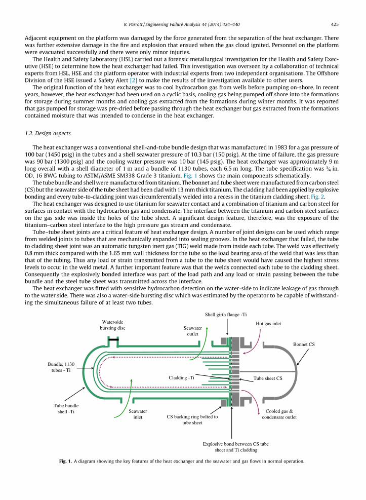
A number of critical components in the heat exchanger structure had failed, as identified in Fig. 3, and were recoveredfrom the platform after the incident. The failed components of particular interest were:
� The cladding and the tube sheet to which it had been bonded, Figs. 4 and 5.� The 1130 fractured welds between the tube and the cladding, Fig. 6.� The fractured girth flange from the shell.� One fractured tube.� The failed seawater side bursting disc.
The components were examined metallurgically and fractographically at HSL, Buxton, to characterise individual fracturemodes and their respective contributions to the overall failure of the heat exchanger.
Water-side bursting disc failed
All tube to cladding welds fractured
Girth flange fractured from shell
One fractured tube
Cladding separated from tube sheet and
deformed
Bonnet, tube sheet and backing ring intact
Fig. 3. A diagram showing the respective positions of the failed components.
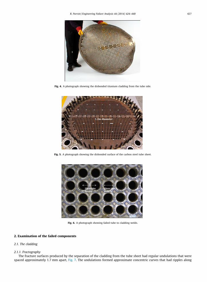
Fig. 4. A photograph showing the disbonded titanium cladding from the tube side.
1.2m diameter
Fig. 5. A photograph showing the disbonded surface of the carbon steel tube sheet.
25mm tube spacing
19mm tube diameter
Fig. 6. A photograph showing failed tube to cladding welds.
R. Parrott / Engineering Failure Analysis 44 (2014) 424–440 427
2. Examination of the failed components
2.1. The cladding
2.1.1. FractographyThe fracture surfaces produced by the separation of the cladding from the tube sheet had regular undulations that were
spaced approximately 1.7 mm apart, Fig. 7. The undulations formed approximate concentric curves that had ripples along

19mm tube diameter
Fig. 7. Cladding fracture showing the ripple pattern.
19mm tube diameter
Spacing ranged from 1.6mm to 1.8mm
Fig. 8. A higher magnification view of the cladding fracture surface showing the dark area surrounding the tube hole
Spacing ranged from 1.6mm to 1.8mm
Fig. 9. A higher magnification photograph showing the cracks found within the darker regions.
428 R. Parrott / Engineering Failure Analysis 44 (2014) 424–440
their length. The curvature of the waves decreased from the lower part of the cladding towards the top and they appeared toradiate from a central point near the bottom of the cladding. Matching fracture features were found on the titanium claddingand the carbon steel tube sheet. The undulations and curvature were characteristic of features that would be expected for afracture path that followed the interface produced by explosively bonding titanium to carbon steel [3]. The uniformity of thefeatures on the fracture surface indicated that the explosive cladding process had produced a consistent bond across thewhole interface between the titanium cladding and the carbon steel tube sheet.
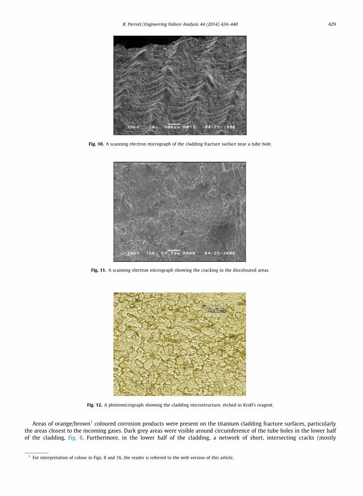
Fig. 10. A scanning electron micrograph of the cladding fracture surface near a tube hole.
Fig. 11. A scanning electron micrograph showing the cracking in the discoloured areas.
Fig. 12. A photomicrograph showing the cladding microstructure, etched in Kroll’s reagent.
R. Parrott / Engineering Failure Analysis 44 (2014) 424–440 429
Areas of orange/brown1 coloured corrosion products were present on the titanium cladding fracture surfaces, particularlythe areas closest to the incoming gases. Dark grey areas were visible around circumference of the tube holes in the lower halfof the cladding, Fig. 8. Furthermore, in the lower half of the cladding, a network of short, intersecting cracks (mostly
1 For interpretation of colour in Figs. 8 and 16, the reader is referred to the web version of this article.
Equiaxed grains in parent metal with no dark etching needles
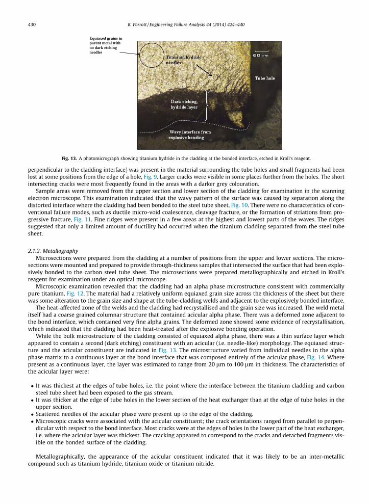
Fig. 13. A photomicrograph showing titanium hydride in the cladding at the bonded interface, etched in Kroll’s reagent.
430 R. Parrott / Engineering Failure Analysis 44 (2014) 424–440
perpendicular to the cladding interface) was present in the material surrounding the tube holes and small fragments had beenlost at some positions from the edge of a hole, Fig. 9. Larger cracks were visible in some places further from the holes. The shortintersecting cracks were most frequently found in the areas with a darker grey colouration.
Sample areas were removed from the upper section and lower section of the cladding for examination in the scanningelectron microscope. This examination indicated that the wavy pattern of the surface was caused by separation along thedistorted interface where the cladding had been bonded to the steel tube sheet, Fig. 10. There were no characteristics of con-ventional failure modes, such as ductile micro-void coalescence, cleavage fracture, or the formation of striations from pro-gressive fracture, Fig. 11. Fine ridges were present in a few areas at the highest and lowest parts of the waves. The ridgessuggested that only a limited amount of ductility had occurred when the titanium cladding separated from the steel tubesheet.
2.1.2. MetallographyMicrosections were prepared from the cladding at a number of positions from the upper and lower sections. The micro-
sections were mounted and prepared to provide through-thickness samples that intersected the surface that had been explo-sively bonded to the carbon steel tube sheet. The microsections were prepared metallographically and etched in Kroll’sreagent for examination under an optical microscope.
Microscopic examination revealed that the cladding had an alpha phase microstructure consistent with commerciallypure titanium, Fig. 12. The material had a relatively uniform equiaxed grain size across the thickness of the sheet but therewas some alteration to the grain size and shape at the tube-cladding welds and adjacent to the explosively bonded interface.
The heat-affected zone of the welds and the cladding had recrystallised and the grain size was increased. The weld metalitself had a coarse grained columnar structure that contained acicular alpha phase. There was a deformed zone adjacent tothe bond interface, which contained very fine alpha grains. The deformed zone showed some evidence of recrystallisation,which indicated that the cladding had been heat-treated after the explosive bonding operation.
While the bulk microstructure of the cladding consisted of equiaxed alpha phase, there was a thin surface layer whichappeared to contain a second (dark etching) constituent with an acicular (i.e. needle-like) morphology. The equiaxed struc-ture and the acicular constituent are indicated in Fig. 13. The microstructure varied from individual needles in the alphaphase matrix to a continuous layer at the bond interface that was composed entirely of the acicular phase, Fig. 14. Wherepresent as a continuous layer, the layer was estimated to range from 20 lm to 100 lm in thickness. The characteristics ofthe acicular layer were:
� It was thickest at the edges of tube holes, i.e. the point where the interface between the titanium cladding and carbonsteel tube sheet had been exposed to the gas stream.� It was thicker at the edge of tube holes in the lower section of the heat exchanger than at the edge of tube holes in the
upper section.� Scattered needles of the acicular phase were present up to the edge of the cladding.� Microscopic cracks were associated with the acicular constituent; the crack orientations ranged from parallel to perpen-
dicular with respect to the bond interface. Most cracks were at the edges of holes in the lower part of the heat exchanger,i.e. where the acicular layer was thickest. The cracking appeared to correspond to the cracks and detached fragments vis-ible on the bonded surface of the cladding.
Metallographically, the appearance of the acicular constituent indicated that it was likely to be an inter-metalliccompound such as titanium hydride, titanium oxide or titanium nitride.
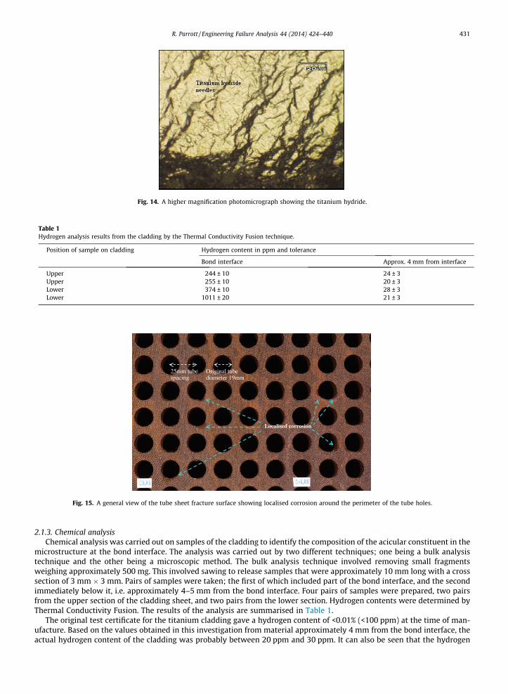
Fig. 14. A higher magnification photomicrograph showing the titanium hydride.
Table 1Hydrogen analysis results from the cladding by the Thermal Conductivity Fusion technique.
Position of sample on cladding Hydrogen content in ppm and tolerance
Bond interface Approx. 4 mm from interface
Upper 244 ± 10 24 ± 3Upper 255 ± 10 20 ± 3Lower 374 ± 10 28 ± 3Lower 1011 ± 20 21 ± 3
25mm tube spacing
Original tube diameter 19mm
Localised corrosion
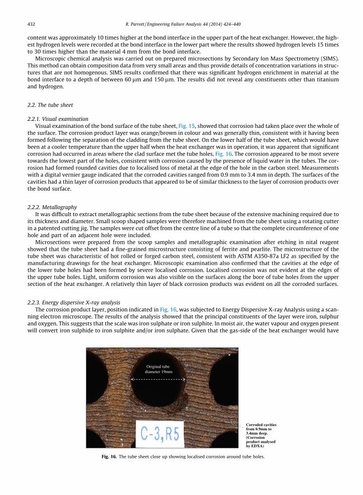
Fig. 15. A general view of the tube sheet fracture surface showing localised corrosion around the perimeter of the tube holes.
R. Parrott / Engineering Failure Analysis 44 (2014) 424–440 431
2.1.3. Chemical analysisChemical analysis was carried out on samples of the cladding to identify the composition of the acicular constituent in the
microstructure at the bond interface. The analysis was carried out by two different techniques; one being a bulk analysistechnique and the other being a microscopic method. The bulk analysis technique involved removing small fragmentsweighing approximately 500 mg. This involved sawing to release samples that were approximately 10 mm long with a crosssection of 3 mm � 3 mm. Pairs of samples were taken; the first of which included part of the bond interface, and the secondimmediately below it, i.e. approximately 4–5 mm from the bond interface. Four pairs of samples were prepared, two pairsfrom the upper section of the cladding sheet, and two pairs from the lower section. Hydrogen contents were determined byThermal Conductivity Fusion. The results of the analysis are summarised in Table 1.
The original test certificate for the titanium cladding gave a hydrogen content of <0.01% (<100 ppm) at the time of man-ufacture. Based on the values obtained in this investigation from material approximately 4 mm from the bond interface, theactual hydrogen content of the cladding was probably between 20 ppm and 30 ppm. It can also be seen that the hydrogen
432 R. Parrott / Engineering Failure Analysis 44 (2014) 424–440
content was approximately 10 times higher at the bond interface in the upper part of the heat exchanger. However, the high-est hydrogen levels were recorded at the bond interface in the lower part where the results showed hydrogen levels 15 timesto 30 times higher than the material 4 mm from the bond interface.
Microscopic chemical analysis was carried out on prepared microsections by Secondary Ion Mass Spectrometry (SIMS).This method can obtain composition data from very small areas and thus provide details of concentration variations in struc-tures that are not homogenous. SIMS results confirmed that there was significant hydrogen enrichment in material at thebond interface to a depth of between 60 lm and 150 lm. The results did not reveal any constituents other than titaniumand hydrogen.
2.2. The tube sheet
2.2.1. Visual examinationVisual examination of the bond surface of the tube sheet, Fig. 15, showed that corrosion had taken place over the whole of
the surface. The corrosion product layer was orange/brown in colour and was generally thin, consistent with it having beenformed following the separation of the cladding from the tube sheet. On the lower half of the tube sheet, which would havebeen at a cooler temperature than the upper half when the heat exchanger was in operation, it was apparent that significantcorrosion had occurred in areas where the clad surface met the tube holes, Fig. 16. The corrosion appeared to be most severetowards the lowest part of the holes, consistent with corrosion caused by the presence of liquid water in the tubes. The cor-rosion had formed rounded cavities due to localised loss of metal at the edge of the hole in the carbon steel. Measurementswith a digital vernier gauge indicated that the corroded cavities ranged from 0.9 mm to 3.4 mm in depth. The surfaces of thecavities had a thin layer of corrosion products that appeared to be of similar thickness to the layer of corrosion products overthe bond surface.
2.2.2. MetallographyIt was difficult to extract metallographic sections from the tube sheet because of the extensive machining required due to
its thickness and diameter. Small scoop shaped samples were therefore machined from the tube sheet using a rotating cutterin a patented cutting jig. The samples were cut offset from the centre line of a tube so that the complete circumference of onehole and part of an adjacent hole were included.
Microsections were prepared from the scoop samples and metallographic examination after etching in nital reagentshowed that the tube sheet had a fine-grained microstructure consisting of ferrite and pearlite. The microstructure of thetube sheet was characteristic of hot rolled or forged carbon steel, consistent with ASTM A350-87a LF2 as specified by themanufacturing drawings for the heat exchanger. Microscopic examination also confirmed that the cavities at the edge ofthe lower tube holes had been formed by severe localised corrosion. Localised corrosion was not evident at the edges ofthe upper tube holes. Light, uniform corrosion was also visible on the surfaces along the bore of tube holes from the uppersection of the heat exchanger. A relatively thin layer of black corrosion products was evident on all the corroded surfaces.
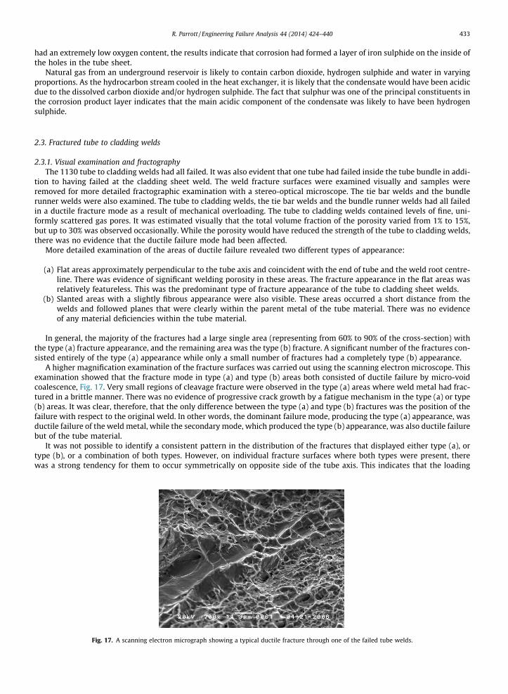
2.2.3. Energy dispersive X-ray analysisThe corrosion product layer, position indicated in Fig. 16, was subjected to Energy Dispersive X-ray Analysis using a scan-
ning electron microscope. The results of the analysis showed that the principal constituents of the layer were iron, sulphurand oxygen. This suggests that the scale was iron sulphate or iron sulphite. In moist air, the water vapour and oxygen presentwill convert iron sulphide to iron sulphite and/or iron sulphate. Given that the gas-side of the heat exchanger would have
Original tube diameter 19mm
Corroded cavities from 0.9mm to 3.4mm deep. (Corrosion product analysed by EDXA)
Fig. 16. The tube sheet close up showing localised corrosion around tube holes.
R. Parrott / Engineering Failure Analysis 44 (2014) 424–440 433
had an extremely low oxygen content, the results indicate that corrosion had formed a layer of iron sulphide on the inside ofthe holes in the tube sheet.
Natural gas from an underground reservoir is likely to contain carbon dioxide, hydrogen sulphide and water in varyingproportions. As the hydrocarbon stream cooled in the heat exchanger, it is likely that the condensate would have been acidicdue to the dissolved carbon dioxide and/or hydrogen sulphide. The fact that sulphur was one of the principal constituents inthe corrosion product layer indicates that the main acidic component of the condensate was likely to have been hydrogensulphide.
2.3. Fractured tube to cladding welds
2.3.1. Visual examination and fractographyThe 1130 tube to cladding welds had all failed. It was also evident that one tube had failed inside the tube bundle in addi-
tion to having failed at the cladding sheet weld. The weld fracture surfaces were examined visually and samples wereremoved for more detailed fractographic examination with a stereo-optical microscope. The tie bar welds and the bundlerunner welds were also examined. The tube to cladding welds, the tie bar welds and the bundle runner welds had all failedin a ductile fracture mode as a result of mechanical overloading. The tube to cladding welds contained levels of fine, uni-formly scattered gas pores. It was estimated visually that the total volume fraction of the porosity varied from 1% to 15%,but up to 30% was observed occasionally. While the porosity would have reduced the strength of the tube to cladding welds,there was no evidence that the ductile failure mode had been affected.
More detailed examination of the areas of ductile failure revealed two different types of appearance:
(a) Flat areas approximately perpendicular to the tube axis and coincident with the end of tube and the weld root centre-line. There was evidence of significant welding porosity in these areas. The fracture appearance in the flat areas wasrelatively featureless. This was the predominant type of fracture appearance of the tube to cladding sheet welds.
(b) Slanted areas with a slightly fibrous appearance were also visible. These areas occurred a short distance from thewelds and followed planes that were clearly within the parent metal of the tube material. There was no evidenceof any material deficiencies within the tube material.
In general, the majority of the fractures had a large single area (representing from 60% to 90% of the cross-section) withthe type (a) fracture appearance, and the remaining area was the type (b) fracture. A significant number of the fractures con-sisted entirely of the type (a) appearance while only a small number of fractures had a completely type (b) appearance.
A higher magnification examination of the fracture surfaces was carried out using the scanning electron microscope. Thisexamination showed that the fracture mode in type (a) and type (b) areas both consisted of ductile failure by micro-voidcoalescence, Fig. 17. Very small regions of cleavage fracture were observed in the type (a) areas where weld metal had frac-tured in a brittle manner. There was no evidence of progressive crack growth by a fatigue mechanism in the type (a) or type(b) areas. It was clear, therefore, that the only difference between the type (a) and type (b) fractures was the position of thefailure with respect to the original weld. In other words, the dominant failure mode, producing the type (a) appearance, wasductile failure of the weld metal, while the secondary mode, which produced the type (b) appearance, was also ductile failurebut of the tube material.
It was not possible to identify a consistent pattern in the distribution of the fractures that displayed either type (a), ortype (b), or a combination of both types. However, on individual fracture surfaces where both types were present, therewas a strong tendency for them to occur symmetrically on opposite side of the tube axis. This indicates that the loading
Fig. 17. A scanning electron micrograph showing a typical ductile fracture through one of the failed tube welds.

434 R. Parrott / Engineering Failure Analysis 44 (2014) 424–440
responsible for failure of the tube to cladding welds probably involved bending which produced type (a) fracture where duc-tile failure initiated at the weld root and type (b) where fracture occurred in the tube material.
2.3.2. Metallographic examinationSamples were removed for microsections from a sample of the welds. The sections were prepared metallographically and
etched in Kroll’s reagent for microscopic examination. Microscopic examination revealed that the tubes had a fine-grained,alpha phase microstructure characteristic of commercial purity titanium in the wrought condition. A range of microstruc-tures were observed in the weld ranging from coarse, equiaxed grains where the tube or cladding sheet been recrystallisedby the heat of welding, to large columnar grains with acicular alpha phase where weld metal had solidified. Gas porosity wasevident in the weld metal but there was no evidence of any adverse constituents, such as hydride or oxide phases, fromwelding.
Microscopic evidence indicated that the welds were of the specified size. It was also evident that the gas side and seawa-ter side surfaces were smooth and that there had been no degradation in service by corrosion, erosion or by the diffusion ofhydrogen. No secondary cracks were visible in the weld sections as might have been expected if the welds had failed by pro-gressive cracking, for example by fatigue.
2.4. Fractured welds between the tube and cladding
There were additional welds where the bundle tie rods and rails were joined to the cladding. These welds had also failedand the appearance of their fracture surfaces was characteristic of ductile failure accompanied by significant plasticdeformation.
2.5. Fractured shell girth flange
According to the manufacturing drawings, the girth flange had been joined to the shell by two circumferential welds,Fig. 18. It was clear that the girth flange had fractured almost entirely through the shell material just beyond one of thetwo welds. There was extensive plastic deformation of the fractured section such that it had become an irregular, twistedshape with little resemblance to the original circular shape of the tube bundle shell. The original perpendicular relationshipbetween the flange surface and the shell was recognisable although the angle had become increased to significantly greaterthan 90�. The increase in the angle between the flange and tube bundle shell indicated that the flange had been deformedtowards the chamber of the heat exchanger. Subsequent examination revealed localised, through-thickness bending of thetube bundle shell around the full circumference of the heat exchanger. The direction of bending was inwards, as explained inFig. 18. The direction of localised bending of the shell was, therefore, consistent with the direction in which the girth flangehad become deformed.
Tube bundle shell -Ti
Shell girth flange -Ti
Tube sheet -CS
Cladding -Ti
Ti-CS explosive bond
Backing ring bolted to tube sheet and clamping girth flange
Failure position of shell
General arrangement before failure
Fig. 18. Original arrangement of girth flange and position of final failure caused by pressurisation and deformation of the separated cladding.

R. Parrott / Engineering Failure Analysis 44 (2014) 424–440 435
Examination of the fracture surfaces indicated that the failure of the shell material was characteristic of ductile fracturedue to bending overload. There were no indications on the fracture surface of pre-existing material defects in the tube bun-dle shell, the flange or the welds. The fracture appearance did not have any characteristics of progressive failure.
A macrosection was prepared from the fractured part of the girth flange. Examination of the etched section revealed noevidence of any material or manufacturing deficiencies in the shell and flange parent materials. Similarly, there were no indi-cations of imperfections in the welds between the tube bundle shell and the flange.
2.6. Tube failure within the bundle
It was apparent that one tube had failed inside the bundle (in addition to its failure at the cladding sheet weld) becausedirectly after the incident, it was found protruding by a length of approximately 1.4 m from the fractured ends of all othertubes. All other tubes were only slightly displaced (20–100 mm) from their original positions and the displacement was inthe opposite direction. The position of the tube failure in the bundle was located by passing a length of welding wire downthe tube as a probe. This positioned the failure approximately 2 m from the rear of the tube bundle. Once located, the failurewas exposed by removing short lengths of tubes between the baffle plates that were nearest to and overlying the indicatedposition.
The fracture was found to have occurred close to the end of the bundle at the transition between the bend and the straightsection of the upper part of the tube. In fact, the two fractured ends had separated by approximately 1.5 m, i.e. the samedistance as the length of tube protruding from the bundle after the failure. The fracture on the front section of the failed tubewas cut out with approximately 200 mm of the tube attached. The fractured end was examined using a stereo-optical micro-scope and the failure was found to be typical of a ductile failure caused by tensile overloading.
2.7. Examination of the seawater side bursting disc
The bursting disc had a star shaped fracture pattern with six petal shaped sections which remained attached to the cir-cumference. It was apparent that the star shaped pattern was caused by the pre-scored grooves in the disc. The petals fromthe failed disc were bent in two directions. The most severe bending was consistent with flow outwards from the seawaterside of the heat exchanger, i.e. the intended direction of failure. The least severe bend was near the tips of the petals and wasconsistent with a reversal of flow after the disc had failed. The fracture surfaces appeared to be smooth and featureless, char-acteristic of a ductile shear failure that occurred when the membrane stress at the base of the pre-scored grooves in thebursting disc exceeded the strength of the material. This fracture mode was therefore consistent with an event on the sea-water side during which the water pressure exceeded the design pressure of the bursting disc.
2.8. Other observations
There was no evidence of fretting or wear of tubes due to rubbing at the points where they passed through baffle plates.Similarly, holes in the baffles had not been enlarged by wear. The outer surfaces of the tubes were generally clean althoughaccumulations of sand and marine debris were present at some points, particularly the far end of the tube bundle. There wasno significant erosion damage of the deflector plate position over the seawater inlet.
3. Assessment of the failure mode
3.1. Materials and manufacture
The results of this investigation have indicated that components examined from the heat exchanger had been manufac-tured according to the specifications given for parent materials in the manufacturer’s drawings. The failure of the heatexchanger involved failure of:
i. The explosive bond between the titanium cladding sheet and the carbon steel tube sheet.ii. All welds between the cladding sheet and the tube bundle.
iii. The shell of the tube bundle adjacent to the girth flange.
Explosive bonding produces a disturbed interface where the metals being bonded undergo a wave like deformation [3]. Itis likely that the process of cladding the tube sheet with titanium was carried out to ASTM B898 [4]. The interface failed com-pletely during the incident so it was not possible to test the quality of the bond that had been achieved at the time of man-ufacture against the requirements of ASTM B898. However, fracture surfaces on the cladding sheet and the tube sheet bothshowed evidence of a pronounced wave pattern across the whole area which indicated that a bond had existed before thefailure. The wave pattern was consistent with a satisfactory explosive bond having been produced at the time of manufac-ture. The microstructure of the titanium and carbon steel indicated that the cladding sheet and tube sheet had both beendeformed in the way that would be expected for explosive bonding. The cladding sheet and tube sheet had also been subject

436 R. Parrott / Engineering Failure Analysis 44 (2014) 424–440
to a stress relief heat treatment after explosive bonding. There was no evidence from this investigation to suggest, therefore,that the explosive bond had failed due to a manufacturing deficiency.
The tube to cladding sheet welds, the tie bar welds and the bundle runner welds had all failed in a ductile fracture modeas a result of mechanical overloading. The tube to cladding sheet welds contained pores that had reduced their cross sectionby 1–15%, but by up to 30% in a few instances. While the porosity would have reduced the weld strength, there was no evi-dence that the ductile failure mode of the tube to cladding welds had been affected by the level of porosity.
The failure of the tube bundle shell had occurred through the shell parent material at the edge of the welds with the girthflange. There was no evidence to indicate that the welds between the shell and the girth flange had weakened the shellmaterial.
In conclusion, no evidence was found in this investigation to suggest that material and/or manufacture deficiencies hadcontributed to the failure of the heat exchanger.
3.2. Design features
The heat exchanger was designed to use titanium for surfaces in contact with seawater and a combination of titanium andcarbon steel for surfaces in contact with the hydrocarbon gas. The transition between the titanium and carbon steel surfaceson the gas side occurred inside the holes of the tube sheet. By design, the titanium–carbon steel transition on the gas sidewas the interface produced by explosive bonding the cladding sheet to the tube sheet. It was a significant feature of the failedheat exchanger that the titanium–carbon steel interface was exposed to the high pressure gas side.
The tube–tube sheet joints are a critical feature in heat exchanger design. A number of joint designs can be used whichrange from welded joints to tubes that are mechanically expanded into sealing grooves. In the heat exchanger under inves-tigation, the tube to cladding sheet joint was a TIG (tungsten inert gas) fusion weld made by an automatic process frominside each tube. The weld was effectively a single sided butt weld with a minimum throat dimension of approximately0.8 mm compared with the 1.65 mm wall thickness for the tube. In fact the quality assurance records show that the man-ufacturer’s acceptance criteria for these welds were a minimum throat width of 0.98 mm and a minimum push out forceof 4 tonnes. It can be seen that with this design, the load bearing area of the weld that was less than that of the tubing. Thusany load or strain transmitted from a tube to the tube sheet would have caused the highest stress levels to occur in the weldmetal. A second important feature of weld design was that the welds connected tubes to the cladding sheet but not directlyto the steel tube sheet. Consequently the explosively bonded interface was part of the load path and load or strain passingbetween the tube bundle and the steel tube sheet would have to be transmitted across the interface.
3.3. Condition of the heat exchanger prior to failure
The evidence suggests that at the time of the failure, there had been no significant corrosion of the titanium parts of theheat exchanger whether they had been in contact with seawater or the hydrocarbon gas stream. There was also no evidenceof degradation by erosion or fatigue, of the tubes, baffle plates or the tube to cladding sheet welds. No features indicative offatigue or stress corrosion cracking were observed, which would have indicated that these processes could have beeninvolved in the failure of the tube shell at the girth flange.
There was significant localised deterioration of the carbon steel tube sheet due to galvanic corrosion. Locally corrosionhad caused several millimetres of metal loss at the interface of tube holes in the lower section of the heat exchanger. Basedon the presence of sulphur in the corrosion products, and the position of the metal loss, it is clear that corrosion of the carbonsteel was caused by contact of the two dissimilar metals in wet conditions and in the presence of hydrogen sulphide.
Microscopic examination revealed clear evidence of significant degradation in the mechanical properties of the explosivebond between the titanium cladding sheet and the carbon steel tube sheet. The degradation was caused by galvanic corro-sion and by extensive formation of titanium hydride in the cladding sheet along the bond interface. A layer of titaniumhydride, which was mainly intermittent but continuous at the edges of tube holes, had been formed over a large proportionof the bond interface in the lower part of the heat exchanger. There was a generally thinner and intermittent hydride layer inthe upper area. Cracking was associated with the titanium hydride where it was present as a continuous layer at the edges ofupper tube holes.
It was not possible to quantify the degradation in the mechanical properties of the bond interface because the completearea had failed. However, typical Charpy impact test results provided by DMC Inc., indicate that a very low fracture tough-ness can be expected in explosively bonded materials when the fracture plane coincides with the bond interface. The pres-ence of titanium hydride would have adversely affected the fracture toughness of the bond interface in three ways. Firstly,the formation of titanium hydride is accompanied by an 18% volume expansion that would cause a jacking or wedging stressacross the bond interface [4]. It is possible that the cracking observed where the microstructure contained the highest levelof titanium hydride could have been caused by this jacking or wedging effect. Secondly, it is known from the literature thattensile tests conducted on titanium alloys containing hydrides failed with zero strain to failure [5]. Therefore, it is probablethat the interface would have had little mechanical strength in areas that contained significant quantities of titaniumhydride. A third mechanism is also possible if, as is known to occur in steels, hydrogen becomes trapped and causespressurisation of microscopic voids and interfaces.

R. Parrott / Engineering Failure Analysis 44 (2014) 424–440 437
The absence of the titanium hydride at any other position in the titanium tubes, and the coincidence of the localised cor-rosion of the tube sheet with the formation of titanium hydride at the bond interface are significant observations. The obser-vations show that the localised corrosion and the presence of the titanium hydride were obviously related. This can beexplained by the liberation of hydrogen as the cathodic step in the corrosion reaction. In aerated conditions, the cathodicreaction in aqueous media would normally be the reduction of oxygen. However, the hydrocarbon gas stream would beessentially free of oxygen and it is reasonable to expect, therefore, that the cathodic reaction produced hydrogen. It is con-cluded that the degradation in mechanical properties of the explosive bond through hydride formation would have occurredprogressively. Thus the progressive degradation of the bond with the titanium cladding was directly attributable to galvaniccorrosion of the carbon steel tube sheet.
3.4. Mechanisms of component failure
Two types of failure mechanism can be identified for components that had failed in the heat exchanger. The first failuremechanism involved separation of the titanium cladding sheet. For the reasons given in Section 3.3, the titanium–carbonsteel interface produced by the explosive bonding would have had inherently low fracture toughness as manufactured.The evidence shows that the fracture toughness of the bond would have been further reduced with time as the layer of tita-nium hydride spread out from the tube holes. It is considered, therefore, that the bond interface failed when the titaniumhydride layer had spread further than a critical distance from the tube holes; in fracture mechanics terms, the area of tita-nium hydride had exceeded the critical defect size for fast fracture. It is also possible that the applied stress acting across thebond interface at the time of failure could have been increased due to:
� Jacking and/or wedging due to the increased volume of titanium hydride.� Pressurisation on the plane of the interface due to the internal area of the cavities produced by localised corrosion.� Tensile and/or bending stresses imposed by deflection of the tubes.� Thermal stresses from the difference in thermal expansion coefficients between titanium and carbon steel.� Blocking of tubes by methane hydrate.
However, it is not possible to determine the relative contributions that each of these made to the failure, or whether therewas more than one source of stress on the bond interface at the time of the incident.
The second failure mechanism, which affected the largest group of components, was mechanical overloading. Compo-nents in this group showed no evidence of degradation in service. The components that had failed by mechanical overloadingincluded:
i. The bursting disc had failed in the manner that would be expected for over-pressurisation of the seawater side.ii. The tube bundle shell had failed adjacent to the girth flange due to mechanical overloading by localised, through-
thickness bending of the shell material. The failure was consistent with leverage of the flange by the deformationof the cladding sheet.
iii. All tube to cladding sheet welds had failed. The welds had failed by an overload mechanism that involved bendingresulting from the dome shaped deformation of the cladding sheet and/or buckling of the tubes.
iv. One tube had failed within the bundle by a tensile overload mechanism.
3.5. Probable failure sequence
Three key stages can be identified in the failure of the heat exchanger as explained in Figs. 18–20. The evidence suggeststhat the primary stage in the failure was galvanic corrosion of the carbon steel tube sheet at the interface with the titaniumcladding, Fig. 19. Corrosion occurred in the wet conditions existing in the lower tubes. The presence of the sulphur in thecorrosion product demonstrates that the condensate was acidic because it contained dissolved hydrogen sulphide fromthe gas stream. This is not to say that the gas stream was sour, i.e. containing �1% hydrogen sulphide, but it does indicatethat the relative proportions of water and hydrogen sulphide were such that the condensate was acidic.
There are two reasons why the presence of hydrogen sulphide is important to the failure. As discussed by Kane [6], it isgenerally considered that the rate of corrosion of carbon steel increases because hydrogen sulphide is source of hydrogenions when dissolved in water. Secondly, hydrogen sulphide promotes the absorption of atomic or nascent hydrogen. Dueto the presence of hydrogen sulphide in the gas stream, corrosion of the carbon steel generated hydrogen that diffused alongthe interface between the titanium cladding and the tube sheet. The hydrogen formed a layer of titanium hydride in the clad-ding which had spread outwards from the tube holes degrading the fracture toughness over an increasing proportion of thebonded interface. It is not possible to quantify the time that the initial stage would have taken but it is considered probablethat it would have required a significant part of the service life of the heat exchanger at the time it failed.
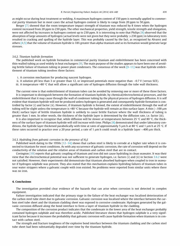
The results of the investigation indicate that the second stage, Fig. 20, was disbonding of the cladding sheet. This probablyoccurred in steps as disbonded areas around each tube increased in size until they linked up. The final stage in the failure prob-ably began when the combined disbonded area exceeded a critical size and the remaining interface disbonded suddenly. Thedetached cladding sheet would then have been deformed rapidly into a domed shape. The rapid deformation of the cladding
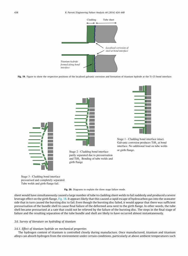
Localised corrosion of steel at bond interface
Tube sheetCladding
Titanium hydride formed along bond interface
Fig. 19. Figure to show the respective positions of the localised galvanic corrosion and formation of titanium hydride at the Ti–CS bond interface.
Stage 1 - Cladding bond interface intact. Galvanic corrosion produces TiH2 at bond interface. No additional load on tube welds or girth flange.Stage 2 - Cladding bond interface
partly separated due to pressurisation and TiH2. Bending of tube welds and girth flange
Stage 3 - Cladding bond interface pressurised and completely separated. Tube welds and girth flange fail.
Fig. 20. Diagrams to explain the three stage failure mode.
438 R. Parrott / Engineering Failure Analysis 44 (2014) 424–440
sheet would have simultaneously caused a large number of tube to cladding sheet welds to fail suddenly and produced a severeleverage effect on the girth flange, Fig. 18. It appears likely that this caused a rapid escape of hydrocarbon gas into the seawaterside that in turn caused the bursting disc to fail. Even though the bursting disc failed, it would appear that there was sufficientpressurisation of the bundle shell to cause final failure of the deformed area next to the girth flange. In other words, the tubeshell became pressurised at a rate that could not be relieved by the failure of the bursting disc. The steps in the final stage offailure and the resulting separation of the tube bundle and shell are likely to have occurred almost instantaneously.
3.6. Survey of literature on hydriding of titanium
3.6.1. Effect of titanium hydride on mechanical propertiesThe hydrogen content of titanium is controlled closely during manufacture. Once manufactured, titanium and titanium
alloys can absorb hydrogen from the environment under certain conditions, particularly at above ambient temperatures such
R. Parrott / Engineering Failure Analysis 44 (2014) 424–440 439
as might occur during heat treatment or welding. A maximum hydrogen content of 150 ppm is normally applied to commer-cial purity titanium but in most cases the actual hydrogen content is likely to range from 20 ppm to 50 ppm.
Berger [7] showed that the room temperature impact strength of titanium was reduced by 8 times when the hydrogencontent increased from 20 ppm to 230 ppm. The other mechanical properties, yield strength, tensile strength and elongation,were not affected by increases in hydrogen content up to 230 ppm. It is interesting to note that Philips [8] observed that theabsorption of large amounts of hydrogen (actual levels were not given but they were probably�230 ppm) in laboratory testsresulted in cracking and spalling of the hydride layer. This was probably caused by the fact, as recognised by Alvarez andothers [4,5] that the volume of titanium hydride is 18% greater than alpha titanium and so its formation would generate largestresses.
3.6.2. Titanium hydride formationThe published work on hydride formation in commercial purity titanium and embrittlement has been concerned with
thin-walled tubing as used widely in heat exchangers [9]. The main purpose of the studies appears to have been one of avoid-ing brittle failure of titanium tubing in power plant condensers. The consensus of the work [9–11] was that hydride embrit-tlement of titanium tubing involves three factors:
i. A corrosion mechanism for producing nascent hydrogen.ii. A solution pH less than 3 or greater than 12, or impressed potentials more negative than �0.7 V (versus SCE).
iii. A temperature >80 �C that will allow a significant rate of hydrogen diffusion through the tube wall thickness.
The current view is that embrittlement of titanium tubes can be avoided by removing one or more of these three factors.It is important to distinguish between the formation of titanium hydride, by chemical/electrochemical processes, and the
embrittlement that it may cause through the wall of condenser tubing by the physical process of hydrogen diffusion. It is selfevident that titanium hydride will not be produced unless hydrogen is generated and consequently hydride formation is con-trolled by factor (i) and factor (ii). However, if titanium hydride is formed, the extent of embrittlement through the wall oftubing will be slight unless the temperature is >80 �C because the hydride will remain as thin surface layer. A thin (�100 lmthick) surface layer of brittle titanium hydride is unlikely to cause brittle fracture where the wall thickness of tubing isgreater than 1 mm. In other words, the thickness of the hydride layer is determined by the diffusion rate, i.e. factor (iii).
It is also important to recognise that, while diffusion will be slower at temperatures between 25 �C and 80 �C, the thick-ness of the surface layer of titanium hydride will still increase with time. Philips [8] demonstrated that under laboratory con-ditions, the hydride layer thickened parabolically with time at rates of approximately 5 lm h at 80 �C and 1 lm h at 25 �C. Ifthese rates occurred in practice over a 20 year period, a rate of 1 lm h could result in a hydride layer �400 lm thick.
3.6.3. Hydriding from galvanic corrosion in the presence of H2SPublished work dating to the 1950s [12–14] shows that carbon steel is likely to corrode at a higher rate when it is con-
nected to titanium for most conditions. As with any occurrence of galvanic corrosion, the rate of corrosion will depend on theconductivity of the solution and the relative areas of titanium and carbon steel that are in contact.
Covington [10] reports that galvanic coupling of titanium and iron did not cause hydriding in clean seawater. It was theirview that the electrochemical potential was not sufficient to generate hydrogen, i.e. factors (i) and (ii) in Section 3.6.2 werenot satisfied. However, their experiments did demonstrate that titanium absorbed hydrogen when coupled to iron in seawa-ter if hydrogen sulphide was present. They also stated that this mechanism explains hydriding failures of titanium tubes insour water strippers where a galvanic couple with iron existed. No problems were reported from similar units where therewas no iron.
4. Conclusions
The investigation provided clear evidence of the hazards that can arise when corrosion is not detected in complexequipment.
Failure investigation indicated that the primary stage in the failure of the heat exchanger was localised deterioration ofthe carbon steel tube sheet due to galvanic corrosion. Galvanic corrosion was localised where the interface between the car-bon steel tube sheet and the titanium cladding sheet was exposed to corrosive condensate. Hydrogen generated by the gal-vanic corrosion diffused along the bond interface to form a layer of titanium hydride in the cladding.
The composition of the corrosion product indicates that the condensate in the lower area of the heat exchanger probablycontained hydrogen sulphide and was therefore acidic. Published literature shows that hydrogen sulphide is a very signif-icant factor because it increases the probability that galvanic corrosion will cause hydride formation when titanium is in con-tact with carbon steel.
The strength and fracture toughness of the explosive bond interface between the titanium cladding and the carbon steeltube sheet had been substantially degraded over time by the titanium hydride.
440 R. Parrott / Engineering Failure Analysis 44 (2014) 424–440
The evidence indicated that the tube bundle and bonnet probably separated due to sudden fracture of the titanium clad-ding from the carbon steel tube sheet. Dome shaped deformation of the dis-bonded cladding due to pressurisation wouldhave applied leverage, which overloaded the shell retention flange.
There was no evidence to indicate failure of a tube or tube to tube sheet weld. Furthermore, these events would have beendetected by the water-side hydrocarbon detection.
There was no evidence to suggest that material or manufacturing deficiencies contributed to any stages of the heatexchanger failure.
The design of the heat exchanger was such that it was susceptible to titanium hydride formation from galvanic corrosionbecause the interface between the titanium cladding sheet and the carbon steel tube sheet was exposed to wet corrosiveconditions.
It is recommended that potential effects of galvanic corrosion and low fracture toughness are considered in both thedesign and the integrity management of structural components manufactured from dissimilar metals by explosive bonding.
Acknowledgements
The author would like to acknowledge:
� The practical assistance given by many colleagues at the Health and Safety Laboratory in this complex investigation.� Information on explosive bonding provided by Mr. J. Banker of the Dynamic Materials Corporation and Mr. N. Henry of
ABB Ltd.� Background and operational details for the heat exchanger provided by HSE Offshore Inspectors and the platform
operator.
References
[1] Marshall K. Rough 47/3B the incredible, conf. proc. on pressure systems failures. Institute of Mechanical Engineers; 2009.[2] HSE Offshore Safety Alert 01/2006. Catastrophic failure of a production cooler. <http://www.hse.gov.uk/offshore/alerts/sa_01_06.htm>.[3] Nobili A, Masri T, Lafont MC. Recent developments in characterization of a titanium–steel explosion bond interface. In: Conf. proc. on reactive metals in
corrosive applications, OR, Sept 1999. p. 89–98.[4] Polmear IJ. Light alloys. Metallurgy of the light metals, pub., Arnold; 1981. p. 168.[5] Alvarez A-M. Hydrogen embrittlement of a metastable beta-titanium alloy. Acta Mater 2004;52(4):1083–8.[6] Kane RD. Role of H2S in behaviour of engineering alloys. Int Met Rev 1985;30(6):291–301.[7] Berger LW, Williams DH, Jaffe RJ. Hydrogen in titanium–aluminium alloys. Trans Metall Soc ASME 1958:509–13.[8] Philips II, Pool P, Shrier LL. Hydride formation during cathodic polarization of Ti – effect of temperature and pH of solution on hydride growth. Corros
Sci 1974;14:533–42.[9] Covington LC. The resistance of titanium tubes to hydrogen embrittlement in surface condensers. International Corrosion Forum; 1967.
[10] Covington LC, Schutz RW. Effects of iron on the corrosion resistance of titanium, industrial applications of titanium and zirconium, STP728. Am SocTest Met 1981:163–80.
[11] Corrosion resistance of Titanium, TIMET, pub by Titanium Metals Corporation; 1997.[12] Bomberger HB. Corrosion properties of titanium in marine environments. J Electrochem Soc 1954;101(9):442–7.[13] ASM Handbook. Volume 13B, Corrosion: Materials, pub ASM International; 2005. p. 282.[14] Cotton JB, Downing BP. Corrosion resistance of titanium to sea water. Trans Inst Mar Eng 1957;69(8):311–9.