ENGINEERING DRAWING SKKK 1021 …ocw.utm.my/file.php/135/CHAPTER_04_-_ORTHOGRAPHIC_DRAWING… ·...
41
ORTHOGRAPHIC DRAWING 10/2/2012 1 Agus Arsad, Azizul Azri Bin Mustaffa ENGINEERING DRAWING SKKK 1021
-
Upload
duongkhanh -
Category
Documents
-
view
230 -
download
0
Transcript of ENGINEERING DRAWING SKKK 1021 …ocw.utm.my/file.php/135/CHAPTER_04_-_ORTHOGRAPHIC_DRAWING… ·...

ORTHOGRAPHIC DRAWING
10/2/2012 1
Agus Arsad, Azizul Azri Bin Mustaffa
ENGINEERING DRAWING
SKKK 1021

LEARNING OUTCOMES
It is expected that students will be able to:
• Identify the significance and application
of the orthographic drawing
• Apply the techniques of orthographic
drawing
• Using the techniques for spacing out
drawing
10/2/2012 2

ORTHOGRAPHIC DRAWING
• INTRODUCTION
• SIGNIFICANCE AND ITS APPLICATION
• BASIC THEORY
– FIRST ANGLE PROJECTION
– THIRD ANGLE PROJECTION
• TECHNIQUES FOR SPACING OUT
DRAWING
10/2/2012 3

INTRODUCTION
• Orthographic projection
o A method to show real shape of an object on a
certain plane
o Projection Plane - plane where the object were
projected
o View Direction – Viewer location from the object
o Three Projections – Front, adjacent and plan/top
view
o Every plane is perpendicular to each other
10/2/2012 4

SIGNIFICANCE & APPLICATION
• In this chapter – transfer the isometric
object to orthographic drawing and
complete the drawing with projection
lines.
• Orthographic projection is a means of
representing a three-dimensional (3D)
object in two dimensions (2D).
• Combination of these 2D shapes will
produce complete info of a component
10/2/2012 5
10/2/2012 6
ENGINEERING THE RESOURCES
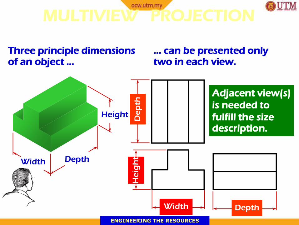
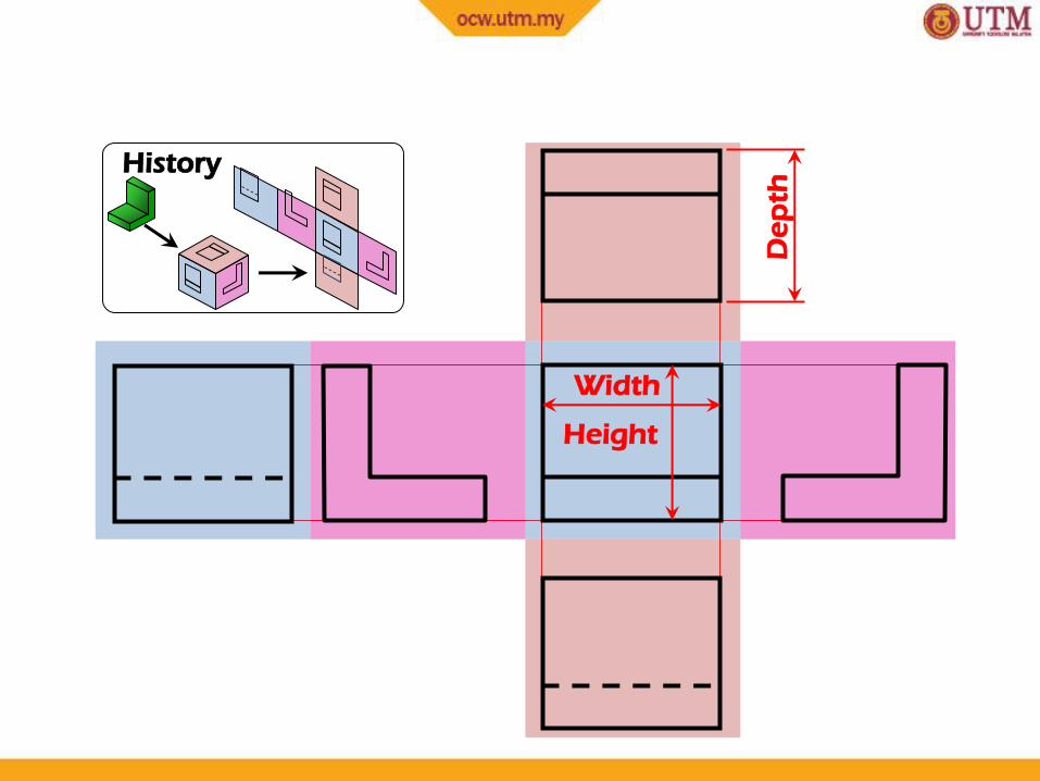
MULTIVIEW PROJECTION
Three principle dimensions of an object …
Width Depth
Height
Width
He
igh
t
Depth
De
pth
… can be presented only two in each view.
Adjacent view(s)
is needed to
fulfill the size description.

10/2/2012 7
ENGINEERING THE RESOURCES
REVOLVE THE OBJECT
Front view Right side view
Top view

10/2/2012 8
PROJECTION SYSTEMS
1. First angle system
2. Third angle system
First Quadrant
Third Quadrant
- European country
- ISO standard
-Canada, USA,
Malaysia, Japan,
Thailand
BASIC THEORY

10/2/2012 9
ORTHOGRAPHIC PROJECTION
1st angle system 3rd angle system
10/2/2012 10
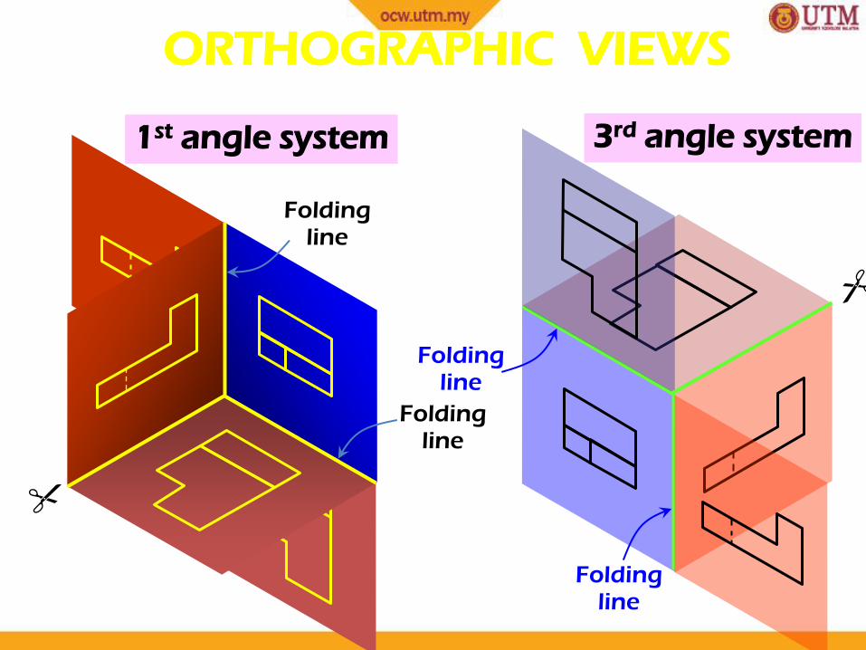
ORTHOGRAPHIC VIEWS
1st angle system 3rd angle system
Folding line
Folding line
Folding line
Folding line

10/2/2012 11
ORTHOGRAPHIC VIEWS
1st angle system 3rd angle system
Front View
Front View
Right Side View
Right Side View
Top View
Top View

10/2/2012 12
First angle system Third angle system
PROJECTION SYMBOLS

10/2/2012 13
PROJECTION SYMBOLS
d 1.7d
2.2d
Suggested proportion
10/2/2012 14
ENGINEERING THE RESOURCES
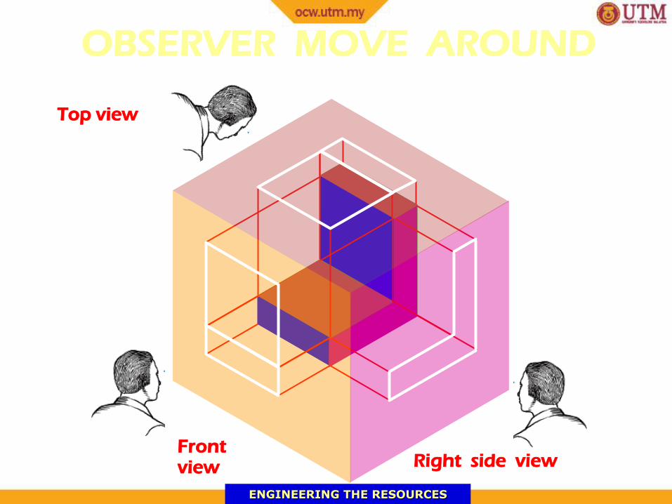
OBSERVER MOVE AROUND
Front view Right side view
Top view

10/2/2012 15
THE GLASS BOX CONCEPT
Bottom view
Left side view
Rear view
10/2/2012 16
Height
Width
De
pth
History

10/2/2012 17
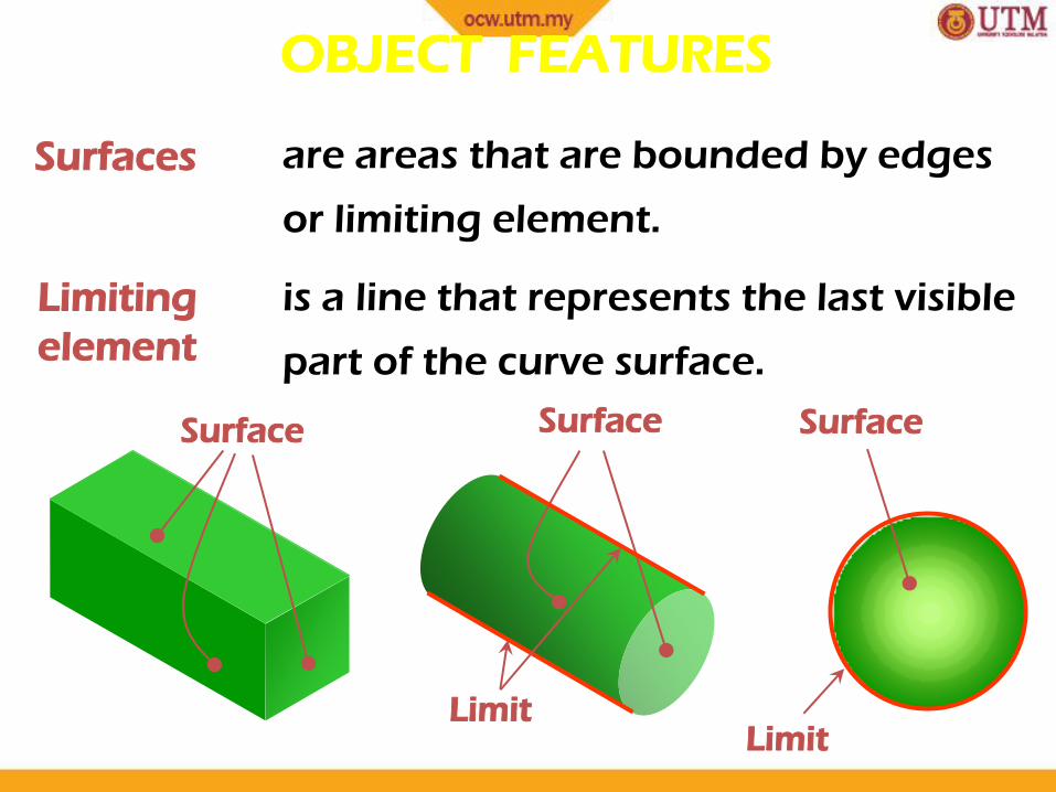
OBJECT FEATURES
Edges are lines that represent the boundary
between two faces.
Corners Represent the intersection of two or
more edges.
Edge
Corner
Edge No edge
No corner No corner
10/2/2012 18
Surfaces are areas that are bounded by edges
or limiting element.
Limiting
element
is a line that represents the last visible
part of the curve surface.
Surface Surface Surface
Limit Limit
OBJECT FEATURES
10/2/2012 19
A
B
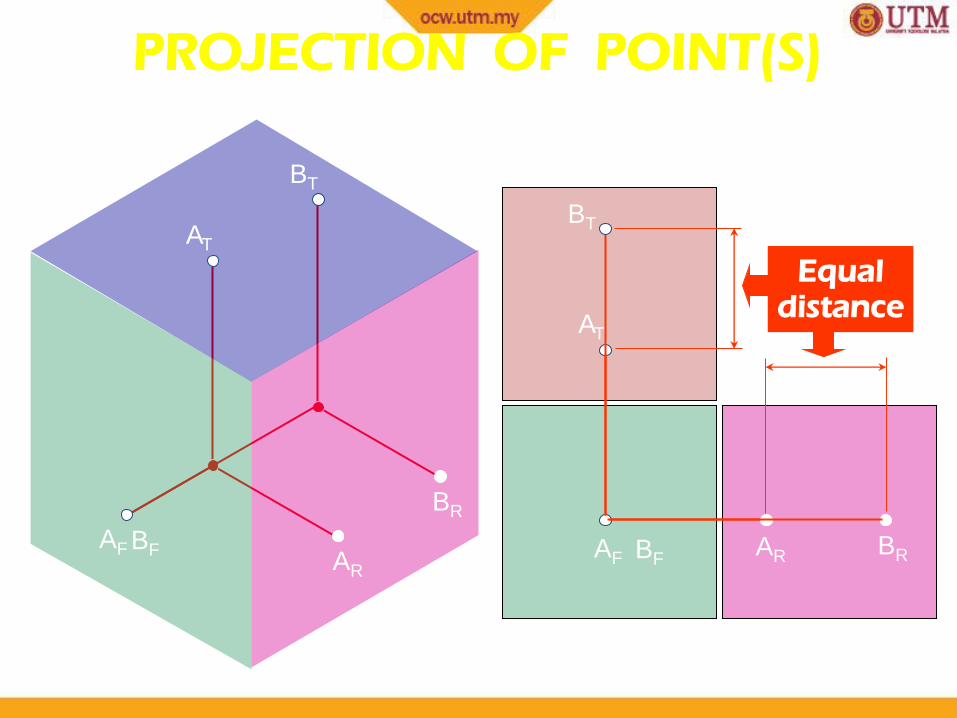
PROJECTION OF POINT(S)
AF
BR
AT
BF AR
BT
AF AR
AT
BF BR
BT
Equal distance
10/2/2012 20
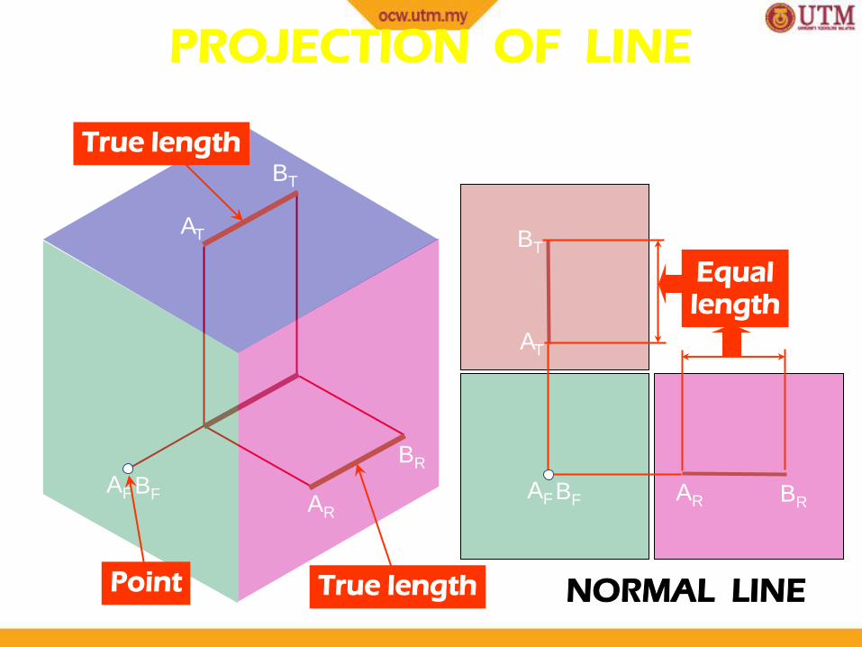
NORMAL LINE
A
B
AF BF BR AR
AT
BT
BR
AR
AF BF
AT
BT
True length
True length Point
Equal length
PROJECTION OF LINE
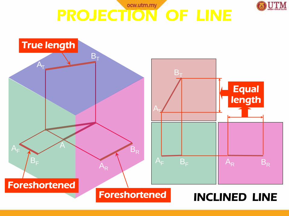
10/2/2012 21
INCLINED LINE
A B
AF BF BR AR
AT
BT
Foreshortened
BR
AR
AF
BF
Foreshortened
AT
BT
True length
A
Equal length
PROJECTION OF LINE
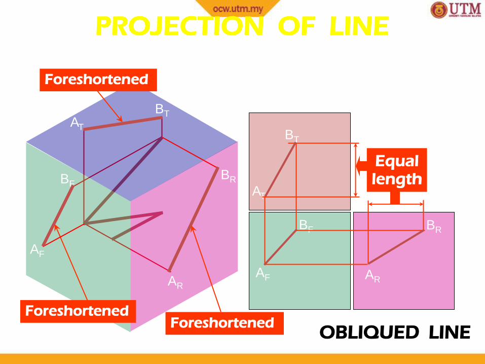
10/2/2012 22
OBLIQUED LINE
A B
AF
BF BR
AR
AT
BT
A
Equal length
B
Foreshortened Foreshortened
Foreshortened
BR
AR
AF
BF
AT
BT
PROJECTION OF LINE
10/2/2012 23
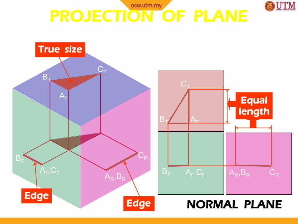
PROJECTION OF PLANE
NORMAL PLANE
B C
A
BF AF,CF CR AR,BR
AT
CT
Equal length
Edge Edge
True size
CR
AR,BR
AF,CF
BF
AT
BT
CT
BT
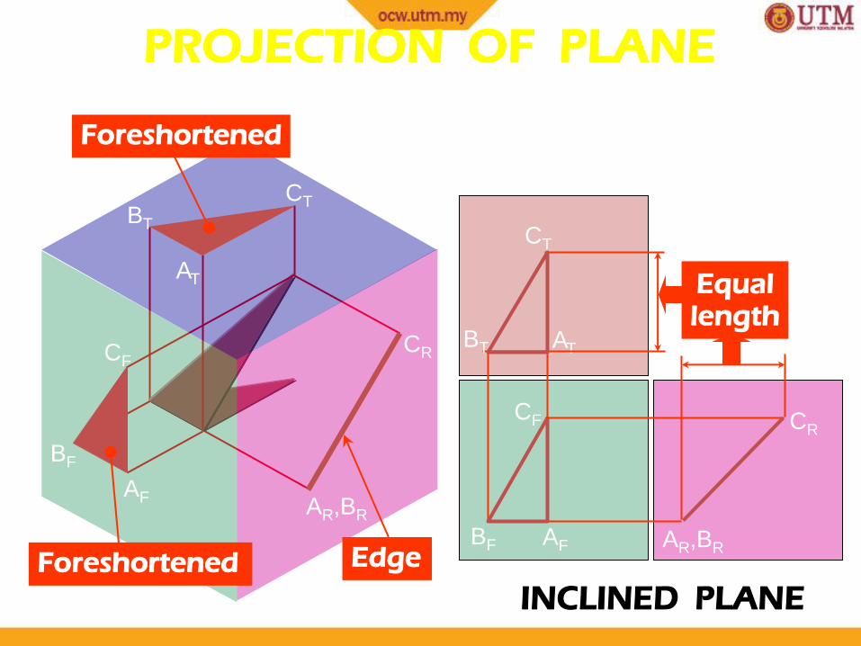
10/2/2012 24 INCLINED PLANE
B C
BF AF
CR
AR,BR
AT
CT
A
Equal length
BT
C
CF
Edge
CR
AR,BR
Foreshortened
BT
CT
AT
AF
CF
Foreshortened
BF
PROJECTION OF PLANE

10/2/2012 25
OBLIQUED PLANE
B C
BF
AF
CR
AR
AT
CT
A
Equal length
BT
C
CF
B
BR
Foreshortened
CR
AR
BR
AF
BF CF
Foreshortened
AT
BT
CT
Foreshortened
PROJECTION OF PLANE
10/2/2012 26
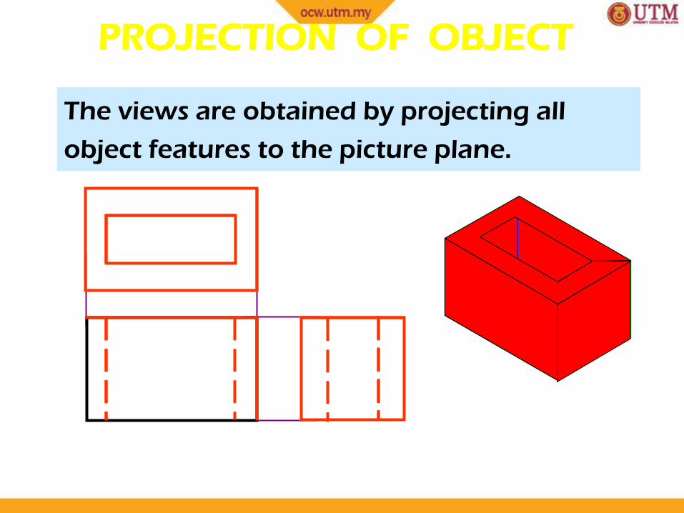
PROJECTION OF OBJECT
The views are obtained by projecting all
object features to the picture plane.

10/2/2012 27
s
s
s
PROJECTION OF OBJECT

10/2/2012 28
PROJECTION OF OBJECT
TECHNIQUES FOR SPACING OUT
DRAWING
• Things to consider
o Selection of the front view
o Selection of the adjacent view
o Method to space out drawing
10/2/2012 29

10/2/2012 30
Select a Front View
The object’s longest dimension should be
presented as a width.
Inappropriate
First choice
GOOD
Second choice
Waste more space

10/2/2012 31
Inappropriate
The adjacent views that are projected from the
selected front view should appear in its natural
position.
Select a Front View

10/2/2012 32
Select a Front View
Choose the view that have the fewest number of hidden lines.
GOOD Inappropriate
10/2/2012 33
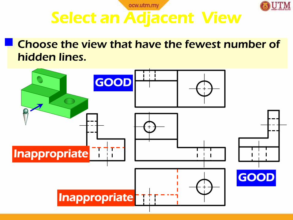
Select an Adjacent View
GOOD
Inappropriate
Inappropriate
GOOD
Choose the view that have the fewest number of hidden lines.
10/2/2012 34
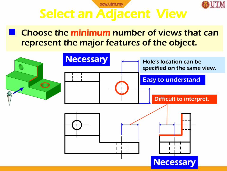
Choose the minimum number of views that can represent the major features of the object.
Select an Adjacent View
Necessary
Necessary
Hole’s location can be specified on the same view.
Difficult to interpret.
Easy to understand
10/2/2012 35
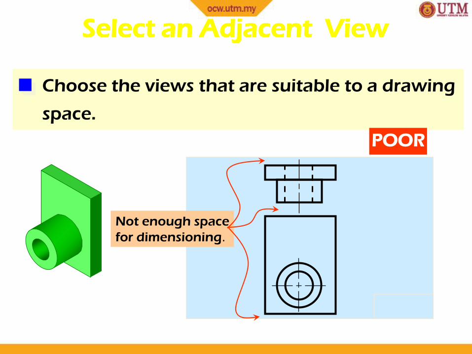
Choose the views that are suitable to a drawing
space.
Select an Adjacent View
POOR
Not enough space
for dimensioning.
10/2/2012 36
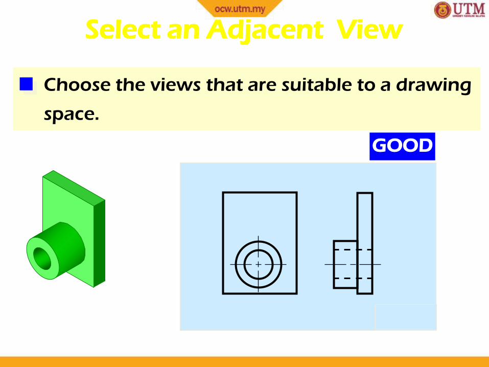
Choose the views that are suitable to a drawing
space.
Select an Adjacent View
GOOD
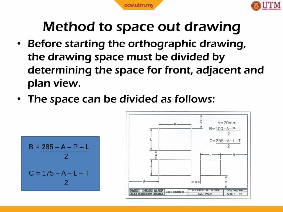
Method to space out drawing • Before starting the orthographic drawing,
the drawing space must be divided by
determining the space for front, adjacent and
plan view.
• The space can be divided as follows:
10/2/2012 37
B = 285 – A – P – L ______________________________________________________________________________________________________________
2
C = 175 – A – L – T - ______________________________________________________________________________________________________________
2

Method to space out drawing (cont’d)
• The drawing space is divided into four quarters
(one quarter-45 degrees line – reflection
reference)
• The visible lines are drawn 10 mm from the
dividing lines
10/2/2012 38

Method to space out drawing (cont’d)
• Projection lines
o Used as guide lines to produce the drawing
o Projected from one edge to another in the other view
o Drawn at a length more than the edge of an object
o Intersections of this line will produce sides of an
object
10/2/2012 39
10/2/2012 40
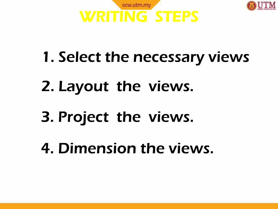
WRITING STEPS
1. Select the necessary views
2. Layout the views.
3. Project the views.
4. Dimension the views.
10/2/2012 41
END
OF
CHAPTER 4
10/2/2012 41