Engineering Development – Materialsf-m-v.dk/documents/00419.pdf · Engineering Development –...
21
Engineering Development – Materials Intelligent material solutions for catalyst technologies Principal Engineer María José Landeira Østergård 1
Transcript of Engineering Development – Materialsf-m-v.dk/documents/00419.pdf · Engineering Development –...

Engineering Development – MaterialsIntelligent material solutions for catalyst technologies
Principal Engineer María José Landeira Østergård1

Hydrogen attack
Stress Corrosion Cracking
Hydrogen Sulphide & CO2
Oxidation
Carburization
Metal Dusting
Synthesis gas: Hydrogen plants and front end of ammonia and methanol plants
Corrosion in HTAS’s related technologies
2
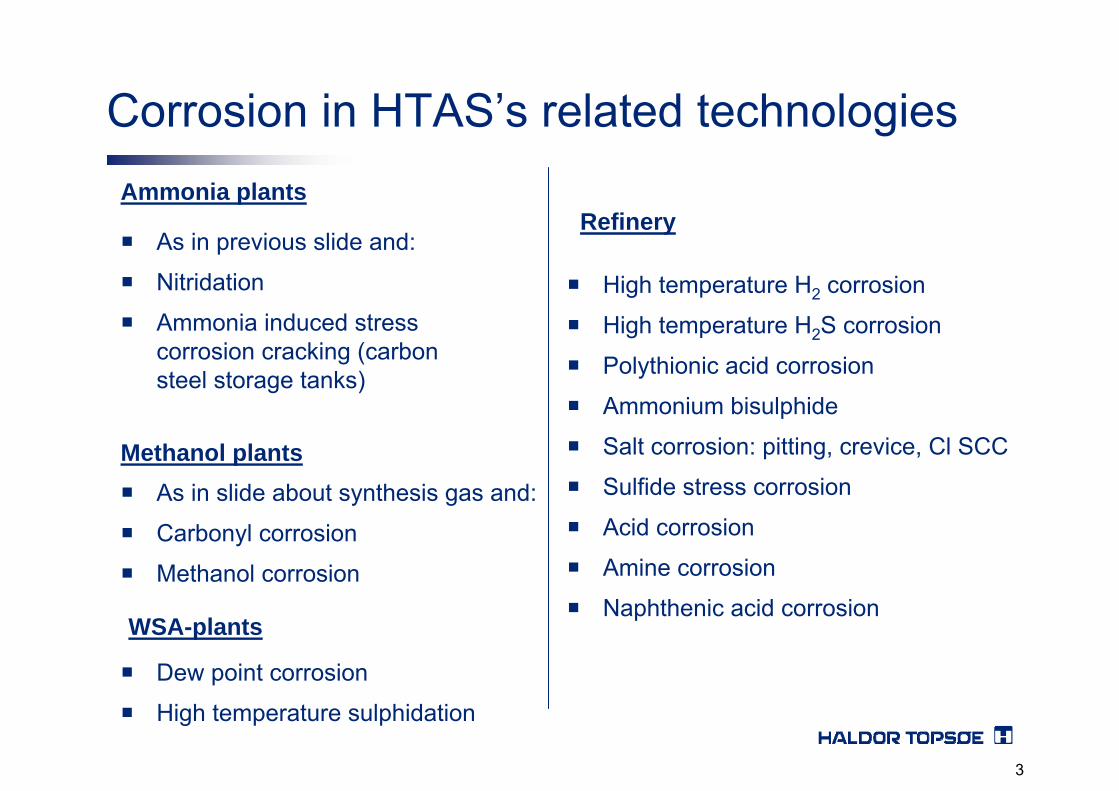
As in previous slide and:
Nitridation
Ammonia induced stress corrosion cracking (carbon steel storage tanks)
Ammonia plants
As in slide about synthesis gas and:
Carbonyl corrosion
Methanol corrosion
Methanol plants
WSA-plants
Dew point corrosion
High temperature sulphidation
High temperature H2 corrosion
High temperature H2S corrosion
Polythionic acid corrosion
Ammonium bisulphide
Salt corrosion: pitting, crevice, Cl SCC
Sulfide stress corrosion
Acid corrosion
Amine corrosion
Naphthenic acid corrosion
Refinery
Corrosion in HTAS’s related technologies
3

After about 5 years of operation severe leakage occurredat the inlet tube sheet of the boiler.
The inlet tube sheet is thermally protected by a layer ofrefractory.
Moreover, several cracks were found in the tube to tube sheet welds, mainly at the centre portion. Severecorrosion was found at the outside of the tubes in thevicinity of the tube sheet.
Case 1: Tubes and Inlet Tube Sheet Waste Heat BoilerEl Segundo Refinery, California.
4

5

7
6
6
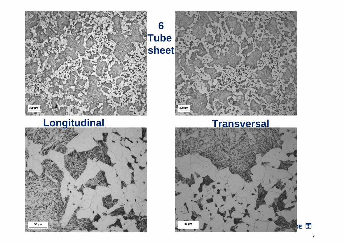
6Tube sheet
Longitudinal Transversal
7

7Tube sheet
Longitudinal
8

The microstructure of the tubes and the tube sheet is pearlite+ferrite with the exception of specimen 7 whichshows spheroidite.
This is a strong indication that only specimen 7 has beenexposed to temperatures above 650 °C
This can only be explained if the refractory has beenmissing.
Tubes and Inlet Tube Sheet Waste Heat BoilerEl Segundo Refinery, California.
9

Case 2: Cracks of Ammonia converter weld, India
• A circumferential weld of one ammonia converter in India was found cracked after 6 months of service by through thickness passing cracks in a circumferential segment of ca 1.5 m, through which hydrogen leakage from the reactor was caused.
• After removal of the external insulation, cracks were found on the external reactor surface, transverse oriented with respect to the circumferential weld and completely contained within the weld metal.
• 20 distinct cracks on the external reactor surface were detected on the external reactor surface in the segment of the leaking weld.
• The following inspection of the inner reactor surface showed that the damage was localised and included a weld segment of ca 1.6 meters.
10

HTAS S-50 Ammonia Converter
20250 mm20250 mm3000 mm169 mm (3x42 + 43 mm multiwall)2.25Cr-1Mo225 bar430 °C182 bar90 bar370 °C420 °C
Straight lenghtTotal LengthInternal diameterWall thicknessShell materialDesign pressureDesign temperatureNormal operation pressureNormal H2 partial pressure Normal operation shell temperatureMax temp. during catalyst reduction
3H2 + N2 ↔2NH3Iron catalyst
Temperature 400 – 500 °CPressures > 100 bar
Recirculation of unconverted synthesis gas
11

Hydrogen uptakeHumid flux
Too large weld beadsToo low weld rate
Large residual stressesToo low temperature at PWHT
Reheat crackingRepear welds
Brittle microstructureToo rapid cooling
Cold crackingToo low interpass temperature
Large grain sizes, reheat crackingToo high heat input
Cold crackingToo low preheat temperature
Risk ofIssue
Fabrication - Welding issues
12
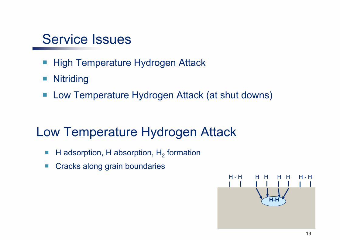
Service IssuesHigh Temperature Hydrogen Attack
Nitriding
Low Temperature Hydrogen Attack (at shut downs)
H adsorption, H absorption, H2 formation
Cracks along grain boundariesH - H H - HH H
H-H
H H
Low Temperature Hydrogen Attack
13

– CH4 formation and decarburization
– Cracks parallel to the surface
H - H H - HH H
CH4
H H
C (from the steel) + 4 H atoms → CH4
High Temperature Hydrogen Attack (HTHA)
14

HTHA – Nelson Diagram
15
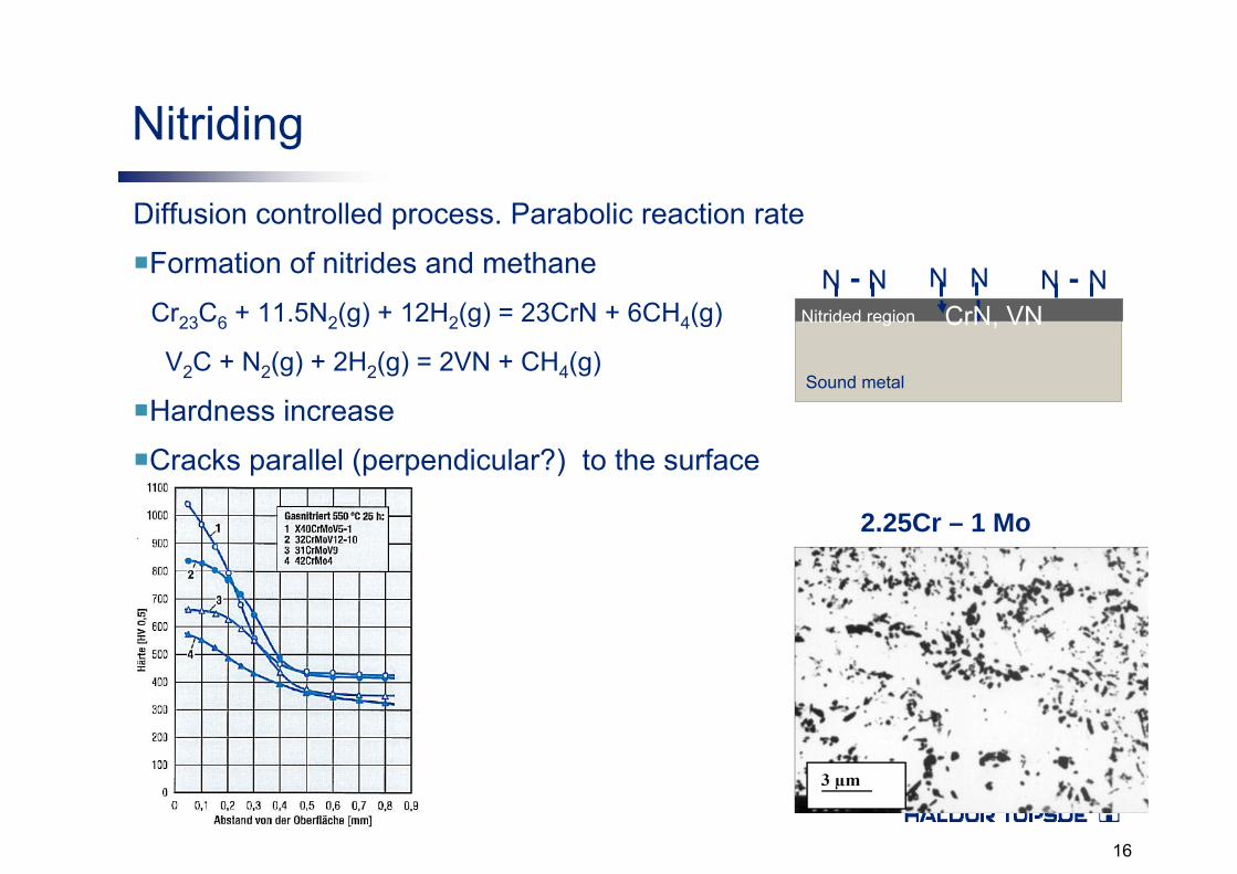
Nitriding
Diffusion controlled process. Parabolic reaction rate
Formation of nitrides and methane
Hardness increase
Cracks parallel (perpendicular?) to the surface
Cr23C6 + 11.5N2(g) + 12H2(g) = 23CrN + 6CH4(g)
V2C + N2(g) + 2H2(g) = 2VN + CH4(g)
N - N N - NN NCrN, VN
Sound metal
Nitrided region
2.25Cr – 1 Mo
16
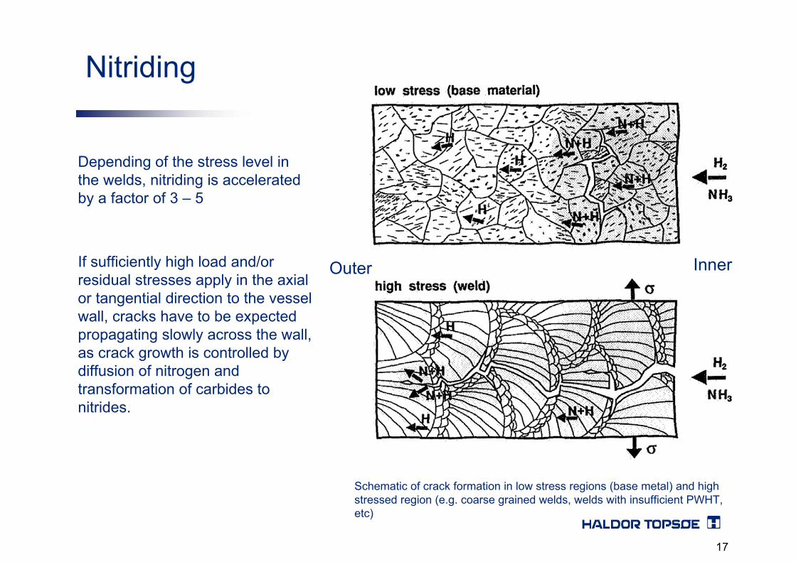
Depending of the stress level in the welds, nitriding is acceleratedby a factor of 3 – 5
If sufficiently high load and/or residual stresses apply in the axial or tangential direction to the vessel wall, cracks have to be expected propagating slowly across the wall, as crack growth is controlled by diffusion of nitrogen and transformation of carbides to nitrides.
Schematic of crack formation in low stress regions (base metal) and high stressed region (e.g. coarse grained welds, welds with insufficient PWHT, etc)
InnerOuter
Nitriding
17

Internal reactor surface
Internal reactor surface
18

Before Stress Relief heat treatment at 690 °C for 1.25 h After Stress Relief heat treatment at 690 °C for 1.25 h
19
Conclusion
• Too elevated hardness values measured in the weld and at the Heat Affected Zone
• Harndess values considered originated by an erroneous or not performed Post Weld Heat Treatment.
• Taking into account the service conditions (presence of gaseous hydrogen and atomic hydrogen) it can be stated, that the part of the circumferential weld of high hardness was subjected to Hydrogen embrittlement.
20

Thanks for your attention
21
![Ocala Banner. (Ocala, Florida) 1909-08-13 [p ].ufdcimages.uflib.ufl.edu/UF/00/04/87/34/00547/00419.pdf · PLACE I Peas TOMATOES Case YOUR TPOT WRAPPING all Pint TELEGRAPH ii a-machineArcadi](https://static.fdocuments.in/doc/165x107/5fcc516d2068ee3467742bd3/ocala-banner-ocala-florida-1909-08-13-p-place-i-peas-tomatoes-case-your.jpg)


![Florida Star. (Titusville, Florida) 1900-05-11 [p 6].ufdcimages.uflib.ufl.edu/UF/00/07/59/01/00419/00155.pdf · stuff Kntii blue ville Brit wile print War belt Oil than thou CURES](https://static.fdocuments.in/doc/165x107/5f22dac04d767e66d4529174/florida-star-titusville-florida-1900-05-11-p-6-stuff-kntii-blue-ville-brit.jpg)