Engineering Data Sheet - WaterSmart Environmental · Engineering Data Sheet ... nearby tank....
19
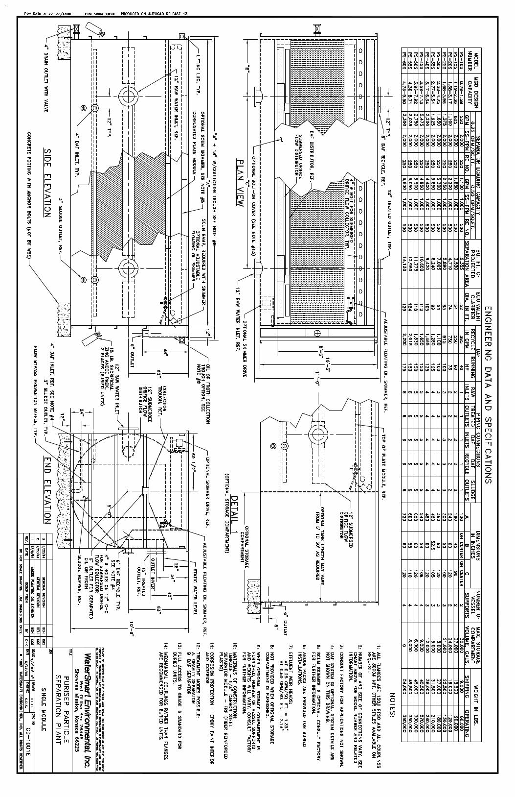
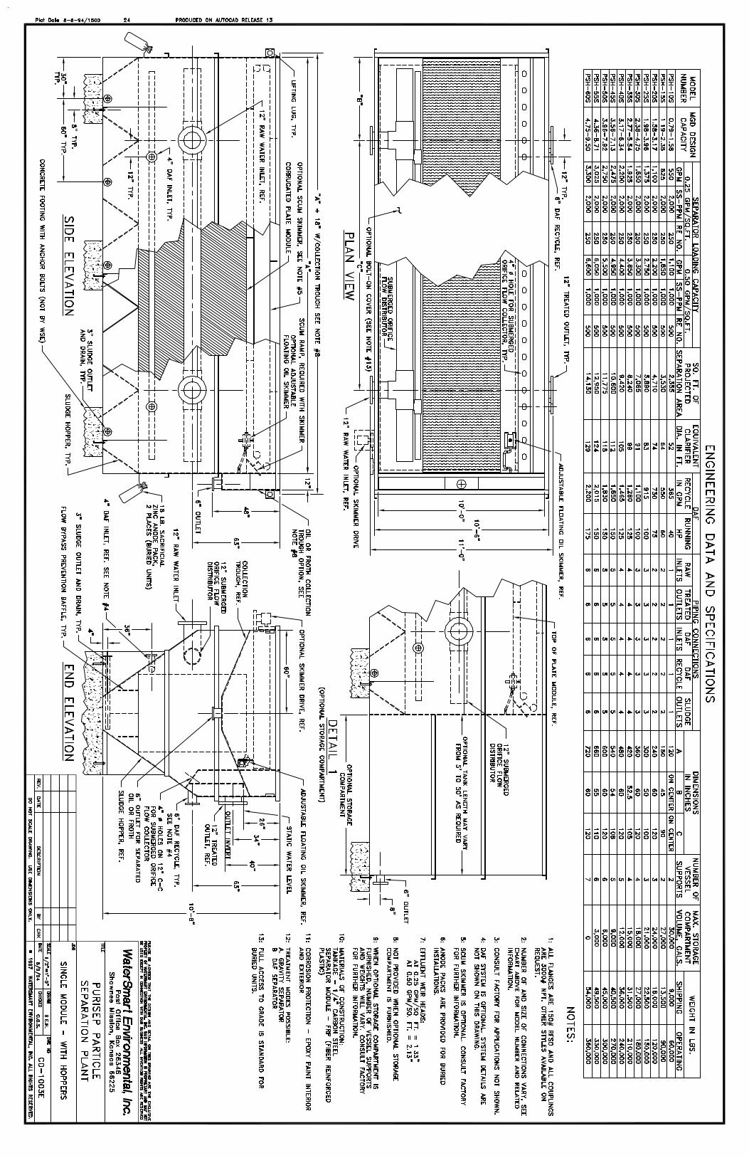
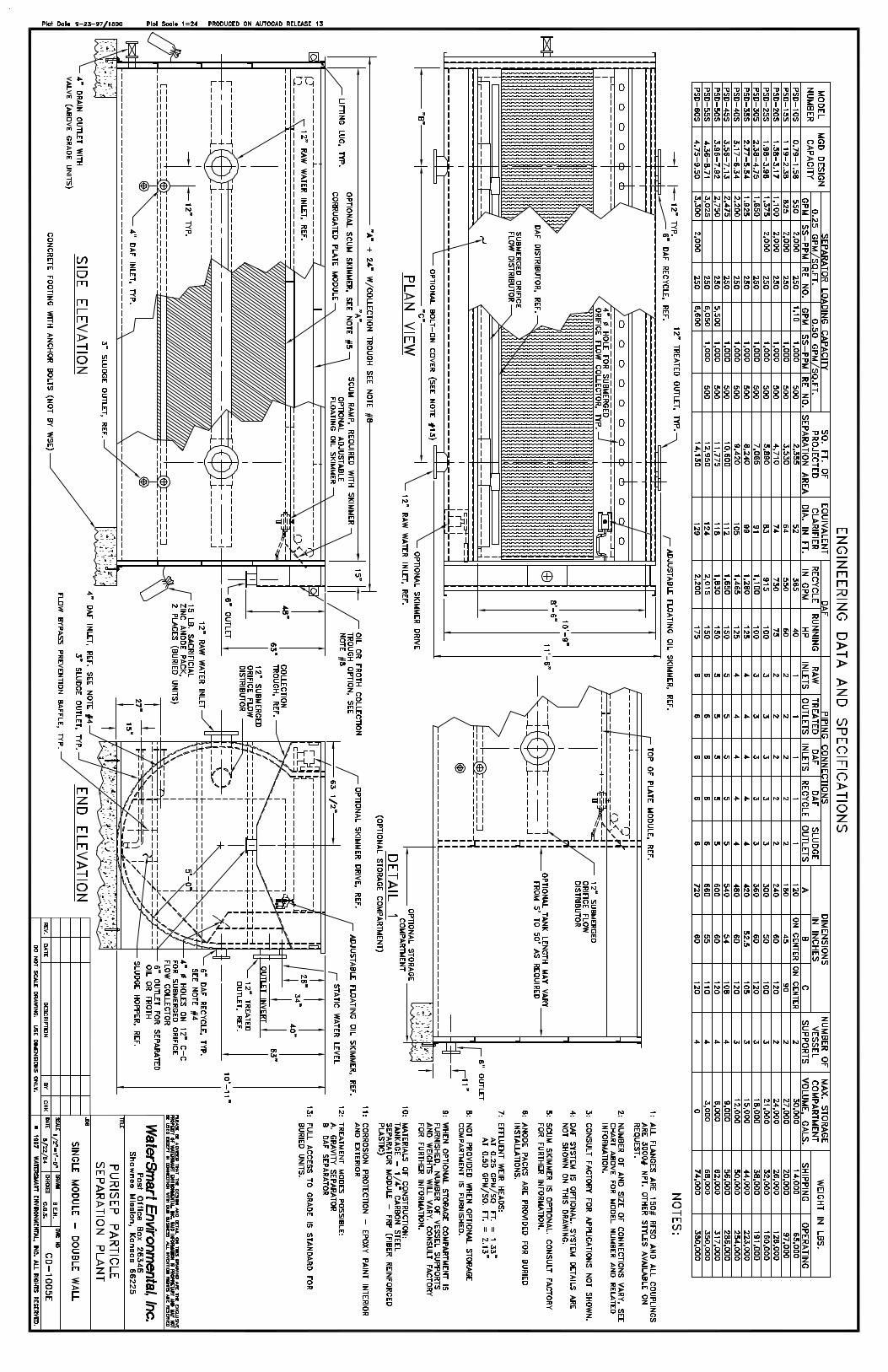
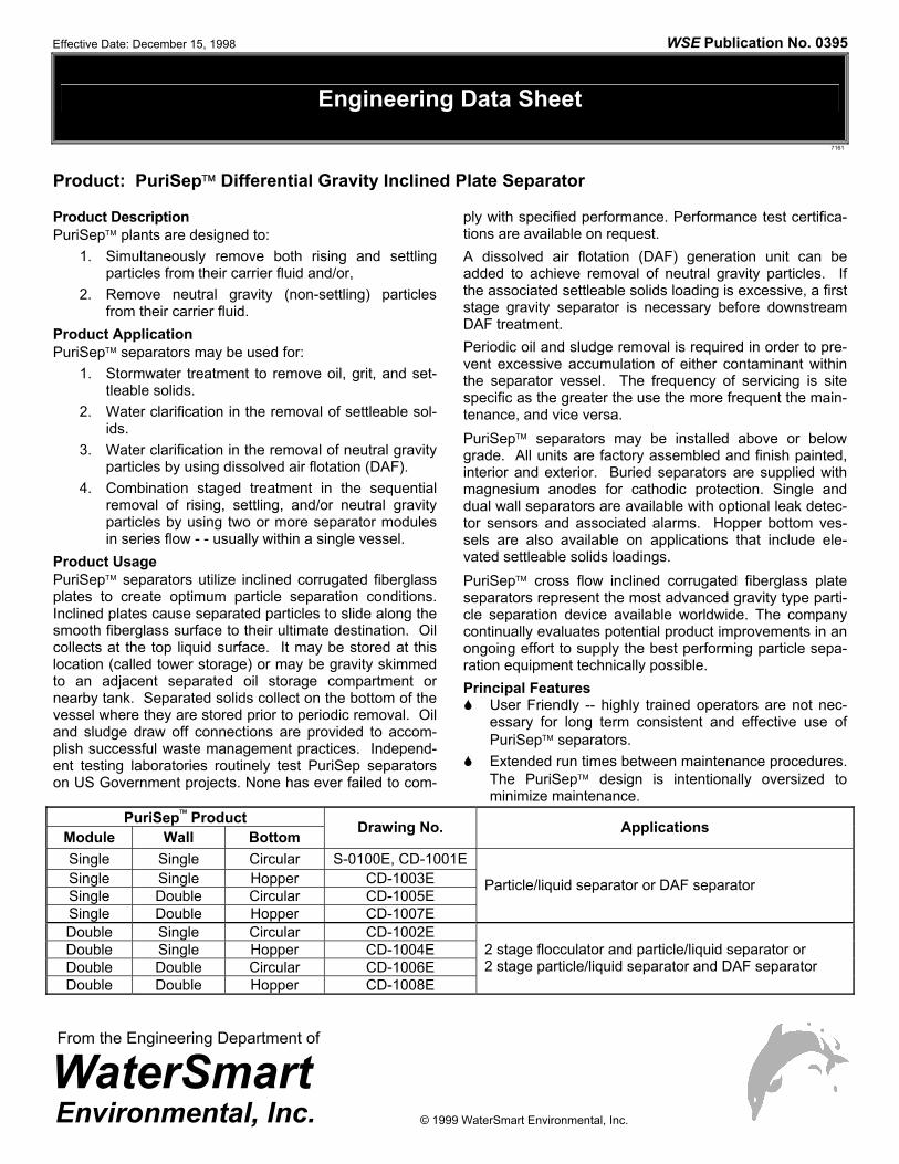
Engineering Data Sheet Product: PuriSep Differential Gravity Inclined Plate Separator Product Description PuriSep plants are designed to: 1. Simultaneously remove both rising and settling particles from their carrier fluid and/or, 2. Remove neutral gravity (non-settling) particles from their carrier fluid. Product Application PuriSep separators may be used for: 1. Stormwater treatment to remove oil, grit, and set- tleable solids. 2. Water clarification in the removal of settleable sol- ids. 3. Water clarification in the removal of neutral gravity particles by using dissolved air flotation (DAF). 4. Combination staged treatment in the sequential removal of rising, settling, and/or neutral gravity particles by using two or more separator modules in series flow - - usually within a single vessel. Product Usage PuriSep separators utilize inclined corrugated fiberglass plates to create optimum particle separation conditions. Inclined plates cause separated particles to slide along the smooth fiberglass surface to their ultimate destination. Oil collects at the top liquid surface. It may be stored at this location (called tower storage) or may be gravity skimmed to an adjacent separated oil storage compartment or nearby tank. Separated solids collect on the bottom of the vessel where they are stored prior to periodic removal. Oil and sludge draw off connections are provided to accom- plish successful waste management practices. Independ- ent testing laboratories routinely test PuriSep separators on US Government projects. None has ever failed to com- ply with specified performance. Performance test certifica- tions are available on request. A dissolved air flotation (DAF) generation unit can be added to achieve removal of neutral gravity particles. If the associated settleable solids loading is excessive, a first stage gravity separator is necessary before downstream DAF treatment. Periodic oil and sludge removal is required in order to pre- vent excessive accumulation of either contaminant within the separator vessel. The frequency of servicing is site specific as the greater the use the more frequent the main- tenance, and vice versa. PuriSep separators may be installed above or below grade. All units are factory assembled and finish painted, interior and exterior. Buried separators are supplied with magnesium anodes for cathodic protection. Single and dual wall separators are available with optional leak detec- tor sensors and associated alarms. Hopper bottom ves- sels are also available on applications that include ele- vated settleable solids loadings. PuriSep cross flow inclined corrugated fiberglass plate separators represent the most advanced gravity type parti- cle separation device available worldwide. The company continually evaluates potential product improvements in an ongoing effort to supply the best performing particle sepa- ration equipment technically possible. Principal Features User Friendly -- highly trained operators are not nec- essary for long term consistent and effective use of PuriSep separators. Extended run times between maintenance procedures. The PuriSep design is intentionally oversized to minimize maintenance. PuriSep Product Module Wall Bottom Drawing No. Applications Single Single Circular S-0100E, CD-1001E Single Single Hopper CD-1003E Single Double Circular CD-1005E Single Double Hopper CD-1007E Particle/liquid separator or DAF separator Double Single Circular CD-1002E Double Single Hopper CD-1004E Double Double Circular CD-1006E Double Double Hopper CD-1008E 2 stage flocculator and particle/liquid separator or 2 stage particle/liquid separator and DAF separator Effective Date: December 15, 1998 WSE Publication No. 0395 7161 From the Engineering Department of © 1999 WaterSmart Environmental, Inc.
-
Upload
truongkhue -
Category
Documents
-
view
220 -
download
0
Transcript of Engineering Data Sheet - WaterSmart Environmental · Engineering Data Sheet ... nearby tank....
Engineering Data Sheet
Product: PuriSep Differential Gravity Inclined Plate Separator
Product Description PuriSep plants are designed to:
1. Simultaneously remove both rising and settling particles from their carrier fluid and/or,
2. Remove neutral gravity (non-settling) particles from their carrier fluid.
Product Application PuriSep separators may be used for:
1. Stormwater treatment to remove oil, grit, and set-tleable solids.
2. Water clarification in the removal of settleable sol-ids.
3. Water clarification in the removal of neutral gravity particles by using dissolved air flotation (DAF).
4. Combination staged treatment in the sequential removal of rising, settling, and/or neutral gravity particles by using two or more separator modules in series flow - - usually within a single vessel.
Product Usage PuriSep separators utilize inclined corrugated fiberglass plates to create optimum particle separation conditions. Inclined plates cause separated particles to slide along the smooth fiberglass surface to their ultimate destination. Oil collects at the top liquid surface. It may be stored at this location (called tower storage) or may be gravity skimmed to an adjacent separated oil storage compartment or nearby tank. Separated solids collect on the bottom of the vessel where they are stored prior to periodic removal. Oil and sludge draw off connections are provided to accom-plish successful waste management practices. Independ-ent testing laboratories routinely test PuriSep separators on US Government projects. None has ever failed to com-
ply with specified performance. Performance test certifica-tions are available on request. A dissolved air flotation (DAF) generation unit can be added to achieve removal of neutral gravity particles. If the associated settleable solids loading is excessive, a first stage gravity separator is necessary before downstream DAF treatment. Periodic oil and sludge removal is required in order to pre-vent excessive accumulation of either contaminant within the separator vessel. The frequency of servicing is site specific as the greater the use the more frequent the main-tenance, and vice versa. PuriSep separators may be installed above or below grade. All units are factory assembled and finish painted, interior and exterior. Buried separators are supplied with magnesium anodes for cathodic protection. Single and dual wall separators are available with optional leak detec-tor sensors and associated alarms. Hopper bottom ves-sels are also available on applications that include ele-vated settleable solids loadings. PuriSep cross flow inclined corrugated fiberglass plate separators represent the most advanced gravity type parti-cle separation device available worldwide. The company continually evaluates potential product improvements in an ongoing effort to supply the best performing particle sepa-ration equipment technically possible. Principal Features
User Friendly -- highly trained operators are not nec-essary for long term consistent and effective use of PuriSep separators.
Extended run times between maintenance procedures. The PuriSep design is intentionally oversized to minimize maintenance.
PuriSep Product Module Wall Bottom Drawing No. Applications
Single Single Circular S-0100E, CD-1001E Single Single Hopper CD-1003E Single Double Circular CD-1005E Single Double Hopper CD-1007E
Particle/liquid separator or DAF separator
Double Single Circular CD-1002E Double Single Hopper CD-1004E Double Double Circular CD-1006E Double Double Hopper CD-1008E
2 stage flocculator and particle/liquid separator or 2 stage particle/liquid separator and DAF separator
Effective Date: December 15, 1998 WSE Publication No. 0395
7161
From the Engineering Department of
© 1999 WaterSmart Environmental, Inc.
Equipment and Performance Specifications
7161
Product: PuriSep Differential Gravity Inclined Plate Separator
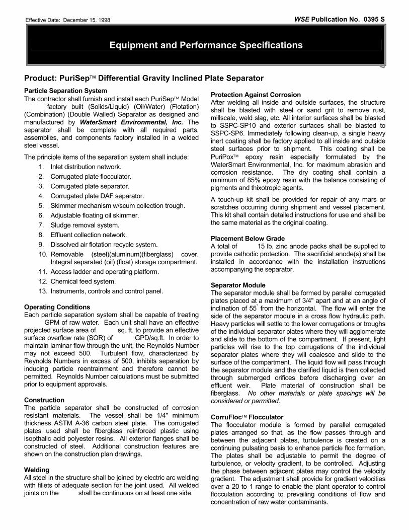
Particle Separation System The contractor shall furnish and install each PuriSep Model factory built (Solids/Liquid) (Oil/Water) (Flotation) (Combination) (Double Walled) Separator as designed and manufactured by WaterSmart Environmental, Inc. The separator shall be complete with all required parts, assemblies, and components factory installed in a welded steel vessel.
The principle items of the separation system shall include: 1. Inlet distribution network. 2. Corrugated plate flocculator. 3. Corrugated plate separator. 4. Corrugated plate DAF separator. 5. Skimmer mechanism w/scum collection trough. 6. Adjustable floating oil skimmer. 7. Sludge removal system. 8. Effluent collection network. 9. Dissolved air flotation recycle system. 10. Removable (steel)(aluminum)(fiberglass) cover.
Integral separated (oil) (float) storage compartment. 11. Access ladder and operating platform. 12. Chemical feed system. 13. Instruments, controls and control panel.
Operating Conditions Each particle separation system shall be capable of treating GPM of raw water. Each unit shall have an effective projected surface area of sq. ft. to provide an effective surface overflow rate (SOR) of GPD/sq.ft. In order to maintain laminar flow through the unit, the Reynolds Number may not exceed 500. Turbulent flow, characterized by Reynolds Numbers in excess of 500, inhibits separation by inducing particle reentrainment and therefore cannot be permitted. Reynolds Number calculations must be submitted prior to equipment approvals.
Construction The particle separator shall be constructed of corrosion resistant materials. The vessel shall be 1/4" minimum thickness ASTM A-36 carbon steel plate. The corrugated plates used shall be fiberglass reinforced plastic using isopthalic acid polyester resins. All exterior flanges shall be constructed of steel. Additional construction features are shown on the construction plan drawings.
Welding All steel in the structure shall be joined by electric arc welding with fillets of adequate section for the joint used. All welded joints on the shall be continuous on at least one side.
Protection Against Corrosion After welding all inside and outside surfaces, the structure shall be blasted with steel or sand grit to remove rust, millscale, weld slag, etc. All interior surfaces shall be blasted to SSPC-SP10 and exterior surfaces shall be blasted to SSPC-SP6. Immediately following clean-up, a single heavy inert coating shall be factory applied to all inside and outside steel surfaces prior to shipment. This coating shall be PuriPox epoxy resin especially formulated by the WaterSmart Environmental, Inc. for maximum abrasion and corrosion resistance. The dry coating shall contain a minimum of 85% epoxy resin with the balance consisting of pigments and thixotropic agents.
A touch-up kit shall be provided for repair of any mars or scratches occurring during shipment and vessel placement. This kit shall contain detailed instructions for use and shall be the same material as the original coating.
Placement Below Grade A total of 15 lb. zinc anode packs shall be supplied to provide cathodic protection. The sacrificial anode(s) shall be installed in accordance with the installation instructions accompanying the separator.
Separator Module The separator module shall be formed by parallel corrugated plates placed at a maximum of 3/4" apart and at an angle of inclination of 55° from the horizontal. The flow will enter the side of the separator module in a cross flow hydraulic path. Heavy particles will settle to the lower corrugations or troughs of the individual separator plates where they will agglomerate and slide to the bottom of the compartment. If present, light particles will rise to the top corrugations of the individual separator plates where they will coalesce and slide to the surface of the compartment. The liquid flow will pass through the separator module and the clarified liquid is then collected through submerged orifices before discharging over an effluent weir. Plate material of construction shall be fiberglass. No other materials or plate spacings will be considered or permitted.
CorruFloc Flocculator The flocculator module is formed by parallel corrugated plates arranged so that, as the flow passes through and between the adjacent plates, turbulence is created on a continuing pulsating basis to enhance particle floc formation. The plates shall be adjustable to permit the degree of turbulence, or velocity gradient, to be controlled. Adjusting the phase between adjacent plates may control the velocity gradient. The adjustment shall provide for gradient velocities over a 20 to 1 range to enable the plant operator to control flocculation according to prevailing conditions of flow and concentration of raw water contaminants.
Effective Date: December 15, 1998 WSE Publication No. 0395 S
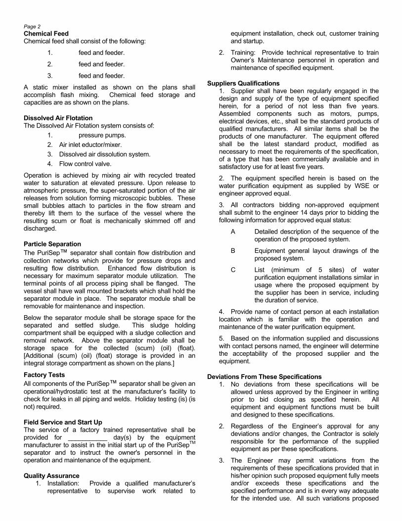
Page 2 Chemical Feed Chemical feed shall consist of the following:
1. feed and feeder.
2. feed and feeder.
3. feed and feeder.
A static mixer installed as shown on the plans shall accomplish flash mixing. Chemical feed storage and capacities are as shown on the plans.
Dissolved Air Flotation The Dissolved Air Flotation system consists of:
1. pressure pumps. 2. Air inlet eductor/mixer. 3. Dissolved air dissolution system. 4. Flow control valve.
Operation is achieved by mixing air with recycled treated water to saturation at elevated pressure. Upon release to atmospheric pressure, the super-saturated portion of the air releases from solution forming microscopic bubbles. These small bubbles attach to particles in the flow stream and thereby lift them to the surface of the vessel where the resulting scum or float is mechanically skimmed off and discharged.
Particle Separation The PuriSep™ separator shall contain flow distribution and collection networks which provide for pressure drops and resulting flow distribution. Enhanced flow distribution is necessary for maximum separator module utilization. The terminal points of all process piping shall be flanged. The vessel shall have wall mounted brackets which shall hold the separator module in place. The separator module shall be removable for maintenance and inspection.
Below the separator module shall be storage space for the separated and settled sludge. This sludge holding compartment shall be equipped with a sludge collection and removal network. Above the separator module shall be storage space for the collected (scum) (oil) (float). [Additional (scum) (oil) (float) storage is provided in an integral storage compartment as shown on the plans.]
Factory Tests All components of the PuriSep™ separator shall be given an operational/hydrostatic test at the manufacturer’s facility to check for leaks in all piping and welds. Holiday testing (is) (is not) required.
Field Service and Start Up The service of a factory trained representative shall be provided for ___________ day(s) by the equipment manufacturer to assist in the initial start up of the PuriSepTM separator and to instruct the owner's personnel in the operation and maintenance of the equipment.
Quality Assurance 1. Installation: Provide a qualified manufacturer’s
representative to supervise work related to
equipment installation, check out, customer training and startup.
2. Training: Provide technical representative to train Owner’s Maintenance personnel in operation and maintenance of specified equipment.
Suppliers Qualifications 1. Supplier shall have been regularly engaged in the design and supply of the type of equipment specified herein, for a period of not less than five years. Assembled components such as motors, pumps, electrical devices, etc., shall be the standard products of qualified manufacturers. All similar items shall be the products of one manufacturer. The equipment offered shall be the latest standard product, modified as necessary to meet the requirements of the specification, of a type that has been commercially available and in satisfactory use for at least five years.
2. The equipment specified herein is based on the water purification equipment as supplied by WSE or engineer approved equal.
3. All contractors bidding non-approved equipment shall submit to the engineer 14 days prior to bidding the following information for approved equal status:
A Detailed description of the sequence of the operation of the proposed system.
B Equipment general layout drawings of the proposed system.
C List (minimum of 5 sites) of water purification equipment installations similar in usage where the proposed equipment by the supplier has been in service, including the duration of service.
4. Provide name of contact person at each installation location which is familiar with the operation and maintenance of the water purification equipment.
5. Based on the information supplied and discussions with contact persons named, the engineer will determine the acceptability of the proposed supplier and the equipment.
Deviations From These Specifications 1. No deviations from these specifications will be
allowed unless approved by the Engineer in writing prior to bid closing as specified herein. All equipment and equipment functions must be built and designed to these specifications.
2. Regardless of the Engineer’s approval for any deviations and/or changes, the Contractor is solely responsible for the performance of the supplied equipment as per these specifications.
3. The Engineer may permit variations from the requirements of these specifications provided that in his/her opinion such proposed equipment fully meets and/or exceeds these specifications and the specified performance and is in every way adequate for the intended use. All such variations proposed
Page 3 by the Contractor shall be called to the attention of the Engineer in writing 14 days prior to the bid opening and shall be made only if approved in writing.
4. Certain design limitations, tests, etc. are herein specified as a partial check on the adequacy of design, fabrication, and materials. These requirements do not cover all features necessary to insure satisfactory and approved operation of the equipment. Conformity of these requirements shall in no way supersede the general requirements as to satisfactory and efficient operation of the equipment.
System Performance 1. The supplier is responsible to design, engineer,
manufacture, supply, and start-up the water purification equipment to satisfactorily treat and clean the wastewater. Satisfactory performance will be gauged by representatives of the owner.
2. The supplier is solely responsible for the equipment performance. Should the equipment not perform as per specifications requirements, the supplier shall modify, and/or alter the equipment supplied at his own expense until the performance is satisfactory. All such changes shall be approved by the engineer.
Warranty 1. Warranty work specified herein is for one (1) year
from substantial completion against defects in materials and in labor and workmanship
2. Defects shall include, but not be limited to:
A. Operation: Noisy, rough or substandard operation.
B. Parts: Loose, damaged and missing parts.
C. Finish: Abnormal deterioration
The supplier guarantees that he is familiar with the cleaning requirements and that the system shall be built to accommo-date such.
From the Engineering Department of
© 1999 WaterSmart Environmental, Inc.
Engineering Data Sheet
Product: PuriSep and SmartWater Differential Gravity Inclined Plate Separators
Process: Flow Bypassing and Contaminant Washout Considerations
First Flush: In the vast majority of significant storm events, rainfall begins rather slowly. Intensity continues to build over the next 20 minutes reaching a peak after about 30 minutes. During the first five minutes, major percent-ages of both oil and solids are washed into the collection system. This is called the “first flush” phenomenon. During the first flush period, the rate of flow is still far be-low the future maximum. Therefore, even though the con-centration of the contaminants during this period is at a maximum, the contaminant removal requirements of the storm-water treatment device remain mild because of the low flow conditions. This is because the quality of the ef-fluent is far more dependent on the rate of flow rather than the concentration of the contaminants.
The Relationship between Projected and Effective Plate Separation Area The Stoke’s Law calculations to determine projected plate separation area do not take into account the efficiency of a separation device. Flow bypassing, flow distribution across the inlet face, treated water collection, and laminar flow all impact on particle removal efficiency. A well de-signed unit such as a PuriSep oil/water separator will ex-hibit 95% particle removal efficiency whereas a poorly de-signed unit may exhibit but 35% efficiency. The Smart-Water stormwater separator exhibits a particle removal efficiency of 85%. Reputable oil/water and stormwater separator manufacturers will have compared the results of their separators against the theoretical results to arrive at the efficiency of operation. This is referred to as an effi-ciency factor.
The efficiency factor multiplied by the pro-jected plate separation area equals the effec-tive separation area. Some manufacturers use a term called a safety factor to reflect the presence of an apparent excess amount of separation area. A 2.86 safety factor, for example, is the same as an efficiency factor of 35% since 100 ÷ 35 equals 2.86.
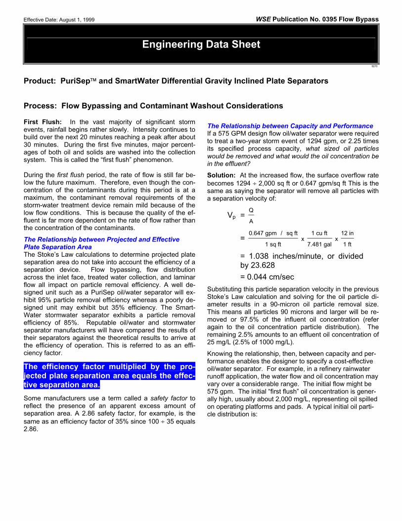
The Relationship between Capacity and Performance If a 575 GPM design flow oil/water separator were required to treat a two-year storm event of 1294 gpm, or 2.25 times its specified process capacity, what sized oil particles would be removed and what would the oil concentration be in the effluent?
Solution: At the increased flow, the surface overflow rate becomes 1294 ÷ 2,000 sq ft or 0.647 gpm/sq ft This is the same as saying the separator will remove all particles with a separation velocity of:
Vp = Q
A
= 0.647 gpm / sq ft
1 sq ftx
1 cu ft
7.481 galx
12 in
1 ft
= 1.038 inches/minute, or divided by 23.628 = 0.044 cm/sec
Substituting this particle separation velocity in the previous Stoke’s Law calculation and solving for the oil particle di-ameter results in a 90-micron oil particle removal size. This means all particles 90 microns and larger will be re-moved or 97.5% of the influent oil concentration (refer again to the oil concentration particle distribution). The remaining 2.5% amounts to an effluent oil concentration of 25 mg/L (2.5% of 1000 mg/L).
Knowing the relationship, then, between capacity and per-formance enables the designer to specify a cost-effective oil/water separator. For example, in a refinery rainwater runoff application, the water flow and oil concentration may vary over a considerable range. The initial flow might be 575 gpm. The initial “first flush” oil concentration is gener-ally high, usually about 2,000 mg/L, representing oil spilled on operating platforms and pads. A typical initial oil parti-cle distribution is:
Effective Date: August 1, 1999 WSE Publication No. 0395 Flow Bypass
9270
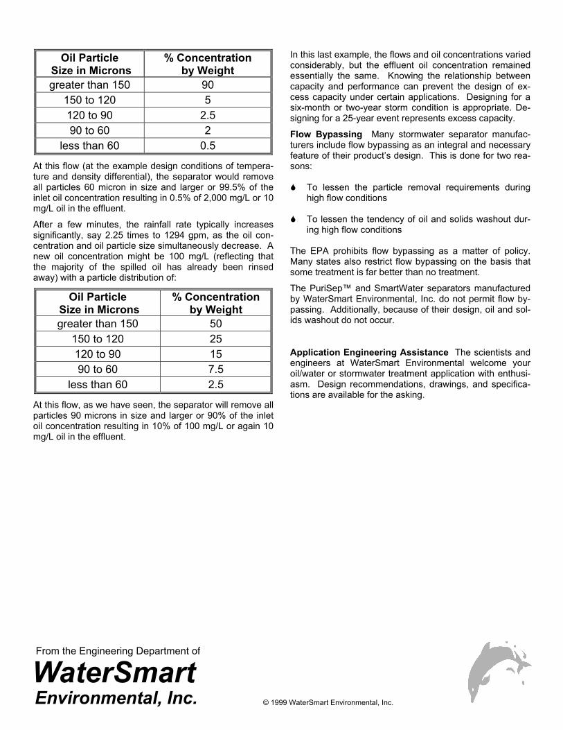
Oil Particle Size in Microns
% Concentration by Weight
greater than 150 90 150 to 120 5 120 to 90 2.5 90 to 60 2
less than 60 0.5
At this flow (at the example design conditions of tempera-ture and density differential), the separator would remove all particles 60 micron in size and larger or 99.5% of the inlet oil concentration resulting in 0.5% of 2,000 mg/L or 10 mg/L oil in the effluent.
After a few minutes, the rainfall rate typically increases significantly, say 2.25 times to 1294 gpm, as the oil con-centration and oil particle size simultaneously decrease. A new oil concentration might be 100 mg/L (reflecting that the majority of the spilled oil has already been rinsed away) with a particle distribution of:
Oil Particle Size in Microns
% Concentration by Weight
greater than 150 50 150 to 120 25 120 to 90 15 90 to 60 7.5
less than 60 2.5
At this flow, as we have seen, the separator will remove all particles 90 microns in size and larger or 90% of the inlet oil concentration resulting in 10% of 100 mg/L or again 10 mg/L oil in the effluent.
In this last example, the flows and oil concentrations varied considerably, but the effluent oil concentration remained essentially the same. Knowing the relationship between capacity and performance can prevent the design of ex-cess capacity under certain applications. Designing for a six-month or two-year storm condition is appropriate. De-signing for a 25-year event represents excess capacity.
Flow Bypassing Many stormwater separator manufac-turers include flow bypassing as an integral and necessary feature of their product’s design. This is done for two rea-sons:
To lessen the particle removal requirements during high flow conditions
To lessen the tendency of oil and solids washout dur-
ing high flow conditions The EPA prohibits flow bypassing as a matter of policy. Many states also restrict flow bypassing on the basis that some treatment is far better than no treatment.
The PuriSep™ and SmartWater separators manufactured by WaterSmart Environmental, Inc. do not permit flow by-passing. Additionally, because of their design, oil and sol-ids washout do not occur.
Application Engineering Assistance The scientists and engineers at WaterSmart Environmental welcome your oil/water or stormwater treatment application with enthusi-asm. Design recommendations, drawings, and specifica-tions are available for the asking.
From the Engineering Department of
© 1999 WaterSmart Environmental, Inc.
Installation, Operation, and Maintenance Instructions
Product: SmartWaterTM Differential Gravity Inclined Plate Stormwater Separator
Installation Inspection Before unloading, inspect the stormwater separator upon delivery for any damage that may have occurred in ship-ment. Areas most susceptible to damage are all nozzles and manway openings. If the separator is damaged, Please notify WaterSmart Environmental, Inc. immediately. The off-loading personnel should note the extent of dam-age and then sign and date the bill of lading. A claim should be immediately filed with the delivering freight car-rier.
Off-Loading The separator must be carefully removed from the truck to prevent damage. Components for the separator may be supplied in a separate carton. Observe proper rigging practices at all times. Equipment hoisting operators should attach a guideline to prevent the separator from swinging out of control. Do not drop the separator in the process of inverting, turning, or moving. Do not slide the separator. In working around the separator, care should be taken to prevent tools from striking it or being dropped inside. Lad-ders used inside or outside in contact with the walls must be wooden or have rubber protection on both ends to pre-vent scratching the surface of the vessel.
Coatings All damaged coatings should be touched up immediately. Please contact the factory or coating manufacturer if your vessel is a special application and more specific informa-tion is required. Under no conditions should chains or ca-bles be put around the separator. Use the lifting eyes on the unit.
Storage If the equipment is not to be installed at time of delivery, it should be stored in an area away from traffic. The ground should be level and free of sharp object that might damage the coatings. All equipment should be stored above the ground on timbers. All factory packing should remain in-tact until the unit is ready for installation. Equipment should be stored indoors, if possible. If not, care should be taken that tanks do not fill with water and debris. Cov-ering all of the equipment with a tarp is strongly recom-mended.
Excavation The excavation must be free from any hard or sharp mate-rial that may cause damage to the tank coating. Care should be exercised during installation to prevent foreign
matter from being introduced into the excavation and/or backfill.
The bottom of the excavation shall be covered with clean sand or gravel to a depth of one foot, suitably graded and leveled.
The excavation shall extend a distance of at least two feet around the perimeter of the tank to provide sufficient clear-ance for sacrificial anodes. The vessel may now be set on a concrete foundation.
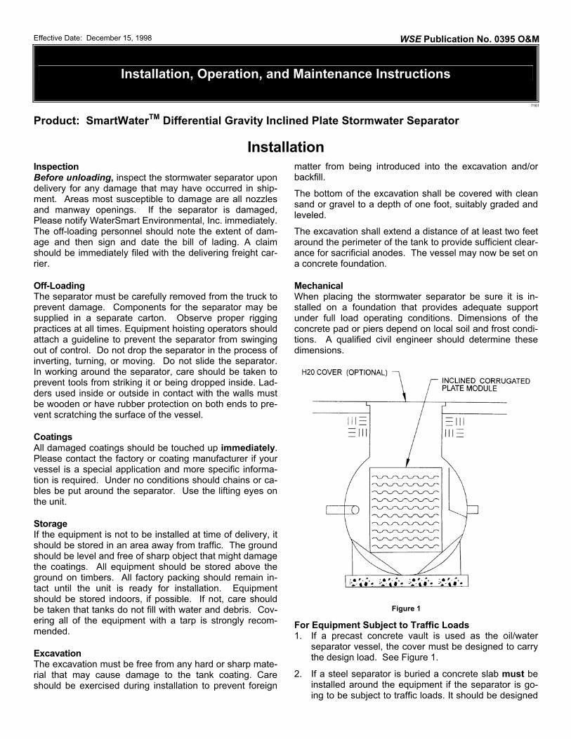
Mechanical When placing the stormwater separator be sure it is in-stalled on a foundation that provides adequate support under full load operating conditions. Dimensions of the concrete pad or piers depend on local soil and frost condi-tions. A qualified civil engineer should determine these dimensions.
For Equipment Subject to Traffic Loads 1. If a precast concrete vault is used as the oil/water
separator vessel, the cover must be designed to carry the design load. See Figure 1.
2. If a steel separator is buried a concrete slab must be installed around the equipment if the separator is go-ing to be subject to traffic loads. It should be designed
Effective Date: December 15, 1998 WSE Publication No. 0395 O&M
7161
Figure 1
2
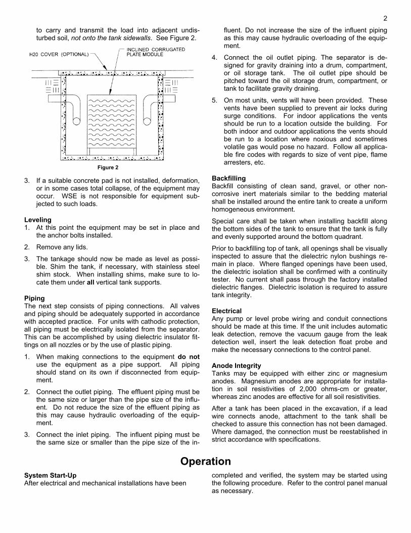
to carry and transmit the load into adjacent undis-turbed soil, not onto the tank sidewalls. See Figure 2.
3. If a suitable concrete pad is not installed, deformation,
or in some cases total collapse, of the equipment may occur. WSE is not responsible for equipment sub-jected to such loads.
Leveling 1. At this point the equipment may be set in place and
the anchor bolts installed.
2. Remove any lids.
3. The tankage should now be made as level as possi-ble. Shim the tank, if necessary, with stainless steel shim stock. When installing shims, make sure to lo-cate them under all vertical tank supports.
Piping The next step consists of piping connections. All valves and piping should be adequately supported in accordance with accepted practice. For units with cathodic protection, all piping must be electrically isolated from the separator. This can be accomplished by using dielectric insulator fit-tings on all nozzles or by the use of plastic piping.
1. When making connections to the equipment do not use the equipment as a pipe support. All piping should stand on its own if disconnected from equip-ment.
2. Connect the outlet piping. The effluent piping must be the same size or larger than the pipe size of the influ-ent. Do not reduce the size of the effluent piping as this may cause hydraulic overloading of the equip-ment.
3. Connect the inlet piping. The influent piping must be the same size or smaller than the pipe size of the in-
fluent. Do not increase the size of the influent piping as this may cause hydraulic overloading of the equip-ment.
4. Connect the oil outlet piping. The separator is de-signed for gravity draining into a drum, compartment, or oil storage tank. The oil outlet pipe should be pitched toward the oil storage drum, compartment, or tank to facilitate gravity draining.
5. On most units, vents will have been provided. These vents have been supplied to prevent air locks during surge conditions. For indoor applications the vents should be run to a location outside the building. For both indoor and outdoor applications the vents should be run to a location where noxious and sometimes volatile gas would pose no hazard. Follow all applica-ble fire codes with regards to size of vent pipe, flame arresters, etc.
Backfilling Backfill consisting of clean sand, gravel, or other non-corrosive inert materials similar to the bedding material shall be installed around the entire tank to create a uniform homogeneous environment.
Special care shall be taken when installing backfill along the bottom sides of the tank to ensure that the tank is fully and evenly supported around the bottom quadrant.
Prior to backfilling top of tank, all openings shall be visually inspected to assure that the dielectric nylon bushings re-main in place. Where flanged openings have been used, the dielectric isolation shall be confirmed with a continuity tester. No current shall pass through the factory installed dielectric flanges. Dielectric isolation is required to assure tank integrity.
Electrical Any pump or level probe wiring and conduit connections should be made at this time. If the unit includes automatic leak detection, remove the vacuum gauge from the leak detection well, insert the leak detection float probe and make the necessary connections to the control panel.
Anode Integrity Tanks may be equipped with either zinc or magnesium anodes. Magnesium anodes are appropriate for installa-tion in soil resistivities of 2,000 ohms-cm or greater, whereas zinc anodes are effective for all soil resistivities.
After a tank has been placed in the excavation, if a lead wire connects anode, attachment to the tank shall be checked to assure this connection has not been damaged. Where damaged, the connection must be reestablished in strict accordance with specifications.
Operation System Start-Up After electrical and mechanical installations have been
completed and verified, the system may be started using the following procedure. Refer to the control panel manual as necessary.
Figure 2
3
1. Verify that all electrical inputs and shutdown indicators are as required per the appropriate control panel man-ual.
2. Turn the power on to the system control panel. Check that all the control functions are properly indicated.
3. Fill the separator with clean water. Allow water to en-ter through the inlet until it begins to flow out of the ef-fluent piping. The floating oil skimmer, if supplied, should be adjusted to 3/32” above the static water level. The unit is now ready for normal operation.
Theory of Operation SmartWater stormwater separators are used to remove small micron sized particles from a liquid flow stream. Particles that rise to the surface (such as oil) and particles that settle to the bottom (sludge) are removed simultaneously. Sometimes, particles neither rise nor settle because their specific gravity is nearly the same as water. Therefore, more than one type of process treatment may be required to achieve the desired degree of particle removal.
Particles contained in a carrier fluid exhibit different densities or specific gravities. Detaining the carrier fluid hydraulically for a sufficient length of time permits the particles to separate out. Particles that rise to the surface of a liquid are said to possess rise rates while particles that settle to the bottom are said to possess settling rates. Stoke’s Law determines the theoretical terminal separation velocities of each type of particle as follows:
Stoke’s Law
Vp = G d d Dp c( )− 2
18η
where Vp = rising or settling velocity of discrete particle
G = gravity constant
η = absolute viscosity of carrier fluid
dp = density of particle to be removed
dc = density of carrier fluid
D = diameter of discrete particle
A negative velocity is referred to as a RISE RATE. Oil, scum, fats, greases, waxes, and other such particles that float to the surface of a liquid are said to possess Rise Rates. A positive velocity is referred to as a SETTLING RATE. All particles that settle to the bottom of a carrier fluid are said to possess Settling Rates. More often than not, both rising and settling particles are present in the same fluid stream.
Traditional separation equipment frequently consists of circular and rectangular clarifiers. In a rectangular unit, for example, of height "H", surface area "A", and hydraulic capacity, or flow-through, of "Q" the residence time "Tr" of the liquid can be determined according to the following equation:
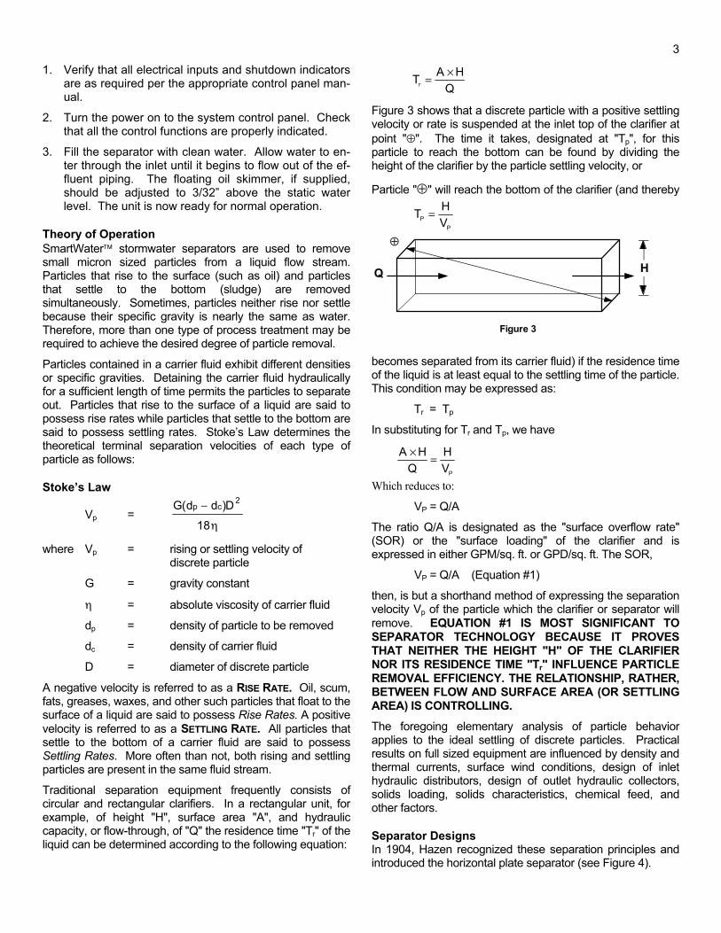
Figure 3 shows that a discrete particle with a positive settling velocity or rate is suspended at the inlet top of the clarifier at point "⊕". The time it takes, designated at "Tp", for this particle to reach the bottom can be found by dividing the height of the clarifier by the particle settling velocity, or
Particle "⊕" will reach the bottom of the clarifier (and thereby
becomes separated from its carrier fluid) if the residence time of the liquid is at least equal to the settling time of the particle. This condition may be expressed as:
Tr = Tp
In substituting for Tr and Tp, we have
Which reduces to:
VP = Q/A
The ratio Q/A is designated as the "surface overflow rate" (SOR) or the "surface loading" of the clarifier and is expressed in either GPM/sq. ft. or GPD/sq. ft. The SOR,
VP = Q/A (Equation #1)
then, is but a shorthand method of expressing the separation velocity Vp of the particle which the clarifier or separator will remove. EQUATION #1 IS MOST SIGNIFICANT TO SEPARATOR TECHNOLOGY BECAUSE IT PROVES THAT NEITHER THE HEIGHT "H" OF THE CLARIFIER NOR ITS RESIDENCE TIME "Tr" INFLUENCE PARTICLE REMOVAL EFFICIENCY. THE RELATIONSHIP, RATHER, BETWEEN FLOW AND SURFACE AREA (OR SETTLING AREA) IS CONTROLLING.
The foregoing elementary analysis of particle behavior applies to the ideal settling of discrete particles. Practical results on full sized equipment are influenced by density and thermal currents, surface wind conditions, design of inlet hydraulic distributors, design of outlet hydraulic collectors, solids loading, solids characteristics, chemical feed, and other factors.
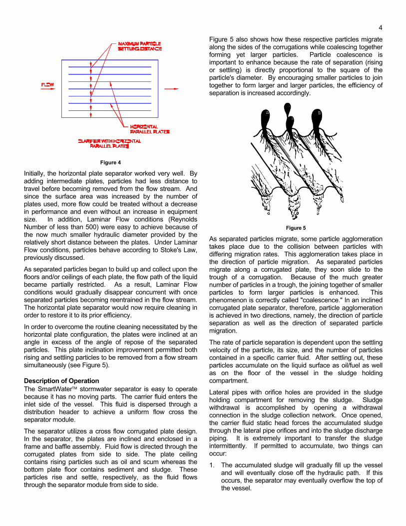
Separator Designs In 1904, Hazen recognized these separation principles and introduced the horizontal plate separator (see Figure 4).
TP =HVP
T A HQr =×
⊕
Q H
Figure 3
A HQ
HVP
× =
4
Figure 4
Initially, the horizontal plate separator worked very well. By adding intermediate plates, particles had less distance to travel before becoming removed from the flow stream. And since the surface area was increased by the number of plates used, more flow could be treated without a decrease in performance and even without an increase in equipment size. In addition, Laminar Flow conditions (Reynolds Number of less than 500) were easy to achieve because of the now much smaller hydraulic diameter provided by the relatively short distance between the plates. Under Laminar Flow conditions, particles behave according to Stoke's Law, previously discussed.
As separated particles began to build up and collect upon the floors and/or ceilings of each plate, the flow path of the liquid became partially restricted. As a result, Laminar Flow conditions would gradually disappear concurrent with once separated particles becoming reentrained in the flow stream. The horizontal plate separator would now require cleaning in order to restore it to its prior efficiency.
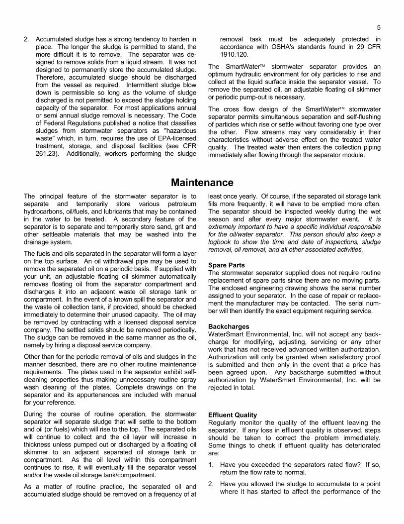
In order to overcome the routine cleaning necessitated by the horizontal plate configuration, the plates were inclined at an angle in excess of the angle of repose of the separated particles. This plate inclination improvement permitted both rising and settling particles to be removed from a flow stream simultaneously (see Figure 5).
Description of Operation The SmartWater stormwater separator is easy to operate because it has no moving parts. The carrier fluid enters the inlet side of the vessel. This fluid is dispersed through a distribution header to achieve a uniform flow cross the separator module.
The separator utilizes a cross flow corrugated plate design. In the separator, the plates are inclined and enclosed in a frame and baffle assembly. Fluid flow is directed through the corrugated plates from side to side. The plate ceiling contains rising particles such as oil and scum whereas the bottom plate floor contains sediment and sludge. These particles rise and settle, respectively, as the fluid flows through the separator module from side to side.
Figure 5 also shows how these respective particles migrate along the sides of the corrugations while coalescing together forming yet larger particles. Particle coalescence is important to enhance because the rate of separation (rising or settling) is directly proportional to the square of the particle's diameter. By encouraging smaller particles to join together to form larger and larger particles, the efficiency of separation is increased accordingly.
Figure 5
As separated particles migrate, some particle agglomeration takes place due to the collision between particles with differing migration rates. This agglomeration takes place in the direction of particle migration. As separated particles migrate along a corrugated plate, they soon slide to the trough of a corrugation. Because of the much greater number of particles in a trough, the joining together of smaller particles to form larger particles is enhanced. This phenomenon is correctly called "coalescence." In an inclined corrugated plate separator, therefore, particle agglomeration is achieved in two directions, namely, the direction of particle separation as well as the direction of separated particle migration.
The rate of particle separation is dependent upon the settling velocity of the particle, its size, and the number of particles contained in a specific carrier fluid. After settling out, these particles accumulate on the liquid surface as oil/fuel as well as on the floor of the vessel in the sludge holding compartment.
Lateral pipes with orifice holes are provided in the sludge holding compartment for removing the sludge. Sludge withdrawal is accomplished by opening a withdrawal connection in the sludge collection network. Once opened, the carrier fluid static head forces the accumulated sludge through the lateral pipe orifices and into the sludge discharge piping. It is extremely important to transfer the sludge intermittently. If permitted to accumulate, two things can occur:
1. The accumulated sludge will gradually fill up the vessel and will eventually close off the hydraulic path. If this occurs, the separator may eventually overflow the top of the vessel.
5
2. Accumulated sludge has a strong tendency to harden in place. The longer the sludge is permitted to stand, the more difficult it is to remove. The separator was de-signed to remove solids from a liquid stream. It was not designed to permanently store the accumulated sludge. Therefore, accumulated sludge should be discharged from the vessel as required. Intermittent sludge blow down is permissible so long as the volume of sludge discharged is not permitted to exceed the sludge holding capacity of the separator. For most applications annual or semi annual sludge removal is necessary. The Code of Federal Regulations published a notice that classifies sludges from stormwater separators as "hazardous waste" which, in turn, requires the use of EPA-licensed treatment, storage, and disposal facilities (see CFR 261.23). Additionally, workers performing the sludge
removal task must be adequately protected in accordance with OSHA's standards found in 29 CFR 1910.120.
The SmartWater stormwater separator provides an optimum hydraulic environment for oily particles to rise and collect at the liquid surface inside the separator vessel. To remove the separated oil, an adjustable floating oil skimmer or periodic pump-out is necessary.
The cross flow design of the SmartWater stormwater separator permits simultaneous separation and self-flushing of particles which rise or settle without favoring one type over the other. Flow streams may vary considerably in their characteristics without adverse effect on the treated water quality. The treated water then enters the collection piping immediately after flowing through the separator module.
Maintenance
The principal feature of the stormwater separator is to separate and temporarily store various petroleum hydrocarbons, oil/fuels, and lubricants that may be contained in the water to be treated. A secondary feature of the separator is to separate and temporarily store sand, grit and other settleable materials that may be washed into the drainage system.
The fuels and oils separated in the separator will form a layer on the top surface. An oil withdrawal pipe may be used to remove the separated oil on a periodic basis. If supplied with your unit, an adjustable floating oil skimmer automatically removes floating oil from the separator compartment and discharges it into an adjacent waste oil storage tank or compartment. In the event of a known spill the separator and the waste oil collection tank, if provided, should be checked immediately to determine their unused capacity. The oil may be removed by contracting with a licensed disposal service company. The settled solids should be removed periodically. The sludge can be removed in the same manner as the oil, namely by hiring a disposal service company.
Other than for the periodic removal of oils and sludges in the manner described, there are no other routine maintenance requirements. The plates used in the separator exhibit self-cleaning properties thus making unnecessary routine spray wash cleaning of the plates. Complete drawings on the separator and its appurtenances are included with manual for your reference.
During the course of routine operation, the stormwater separator will separate sludge that will settle to the bottom and oil (or fuels) which will rise to the top. The separated oils will continue to collect and the oil layer will increase in thickness unless pumped out or discharged by a floating oil skimmer to an adjacent separated oil storage tank or compartment. As the oil level within this compartment continues to rise, it will eventually fill the separator vessel and/or the waste oil storage tank/compartment.
As a matter of routine practice, the separated oil and accumulated sludge should be removed on a frequency of at
least once yearly. Of course, if the separated oil storage tank fills more frequently, it will have to be emptied more often. The separator should be inspected weekly during the wet season and after every major stormwater event. It is extremely important to have a specific individual responsible for the oil/water separator. This person should also keep a logbook to show the time and date of inspections, sludge removal, oil removal, and all other associated activities.
Spare Parts The stormwater separator supplied does not require routine replacement of spare parts since there are no moving parts. The enclosed engineering drawing shows the serial number assigned to your separator. In the case of repair or replace-ment the manufacturer may be contacted. The serial num-ber will then identify the exact equipment requiring service.
Backcharges WaterSmart Environmental, Inc. will not accept any back-charge for modifying, adjusting, servicing or any other work that has not received advanced written authorization. Authorization will only be granted when satisfactory proof is submitted and then only in the event that a price has been agreed upon. Any backcharge submitted without authorization by WaterSmart Environmental, Inc. will be rejected in total.
Effluent Quality Regularly monitor the quality of the effluent leaving the separator. If any loss in effluent quality is observed, steps should be taken to correct the problem immediately. Some things to check if effluent quality has deteriorated are:
1. Have you exceeded the separators rated flow? If so, return the flow rate to normal.
2. Have you allowed the sludge to accumulate to a point where it has started to affect the performance of the
6
separator? If so, take steps to have the sludge re-moved immediately. If it cannot be pumped out, you will have to drain the tank and remove the accumu-lated sludge manually.
3. Check the influent for surfactants or chemical emulsifi-ers. If any are present, you may need chemical pre-treatment to counteract the effects of such agents.
4. Are you pumping into the separator? If so, you may be emulsifying the influent oil. Sample the oil/water from both before and after the pump. There should be no differences between the two samples. If you are mechanically emulsifying the oil you may have to change your influent pump to a low RPM positive dis-placement pump or similar pump that will cut down on shearing.
5. Check to make sure that the oil can freely drain from the equipment. If the oil outlet gets plugged, the oil will flood the oil/water separation chamber and will eventually pass out the effluent.
6. Caution - Before entering an oil/water separator ves-sel one should become familiar with OSHA confined tank entry regulations. A body harness w/rope to a buddy worker, self-breathing apparatus, testing tank environment for explosive and toxic gases, and similar
precautions may be required before tank entry for worker safety.
Product Warranty All SmartWater inclined plate stormwater separator mod-ules are guaranteed for a minimum of five (5) years from date of installation. If the oil/water separator is furnished on a factory packaged basis, the steel tankage carries a 30 year mechanical warranty. If furnished within a con-crete vessel, WaterSmart Environmental, Inc.’s warranty is limited to the 5 year guarantee of the inclined plate sepa-rator module(s).
Performance Testing/Monitoring Annual or more frequent testing of oil/water separator ef-fluent quality is normal. Prior to acceptance of an oil/water separator it is an excellent practice to artificially simulate the design conditions in order to establish the true per-formance of the unit. Influent and effluent samples can then be taken and tested in order to substantiate the de-sign. WaterSmart Environmental, Inc. will be pleased to provide a step by step performance test procedure upon request.
From the Engineering Department of
© 1999 WaterSmart Environmental, Inc.
Mechanical Warranty 7316
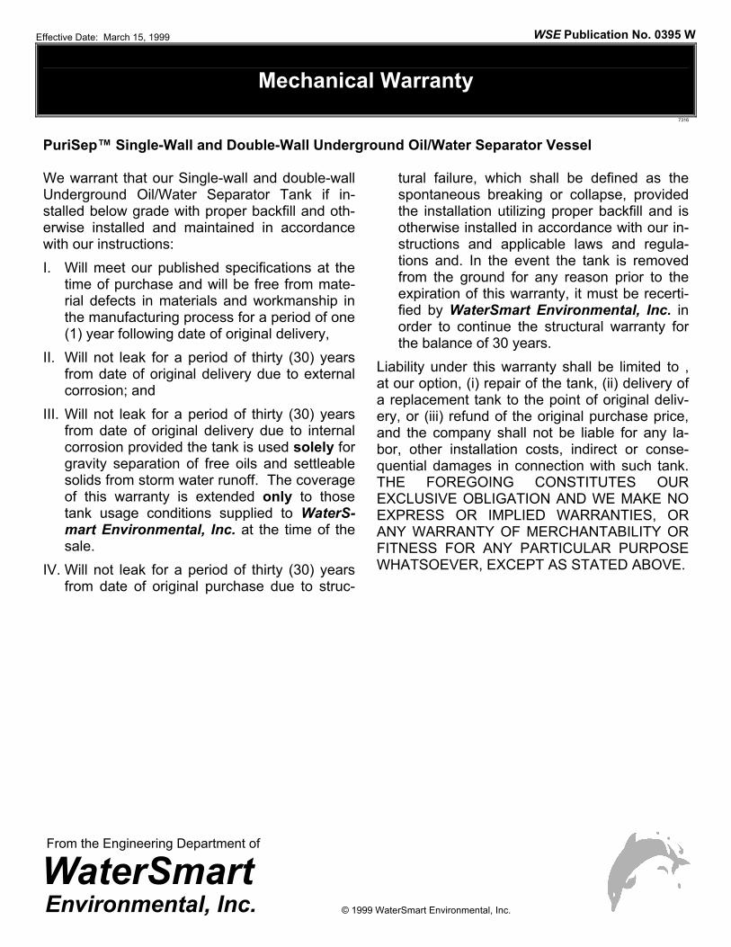
PuriSep™ Single-Wall and Double-Wall Underground Oil/Water Separator Vessel We warrant that our Single-wall and double-wall Underground Oil/Water Separator Tank if in-stalled below grade with proper backfill and oth-erwise installed and maintained in accordance with our instructions: I. Will meet our published specifications at the
time of purchase and will be free from mate-rial defects in materials and workmanship in the manufacturing process for a period of one (1) year following date of original delivery,
II. Will not leak for a period of thirty (30) years from date of original delivery due to external corrosion; and
III. Will not leak for a period of thirty (30) years from date of original delivery due to internal corrosion provided the tank is used solely for gravity separation of free oils and settleable solids from storm water runoff. The coverage of this warranty is extended only to those tank usage conditions supplied to WaterS-mart Environmental, Inc. at the time of the sale.
IV. Will not leak for a period of thirty (30) years from date of original purchase due to struc-
tural failure, which shall be defined as the spontaneous breaking or collapse, provided the installation utilizing proper backfill and is otherwise installed in accordance with our in-structions and applicable laws and regula-tions and. In the event the tank is removed from the ground for any reason prior to the expiration of this warranty, it must be recerti-fied by WaterSmart Environmental, Inc. in order to continue the structural warranty for the balance of 30 years.
Liability under this warranty shall be limited to , at our option, (i) repair of the tank, (ii) delivery of a replacement tank to the point of original deliv-ery, or (iii) refund of the original purchase price, and the company shall not be liable for any la-bor, other installation costs, indirect or conse-quential damages in connection with such tank. THE FOREGOING CONSTITUTES OUR EXCLUSIVE OBLIGATION AND WE MAKE NO EXPRESS OR IMPLIED WARRANTIES, OR ANY WARRANTY OF MERCHANTABILITY OR FITNESS FOR ANY PARTICULAR PURPOSE WHATSOEVER, EXCEPT AS STATED ABOVE.
Effective Date: March 15, 1999 WSE Publication No. 0395 W
From the Engineering Department of
© 1999 WaterSmart Environmental, Inc.
Mechanical Warranty 7316
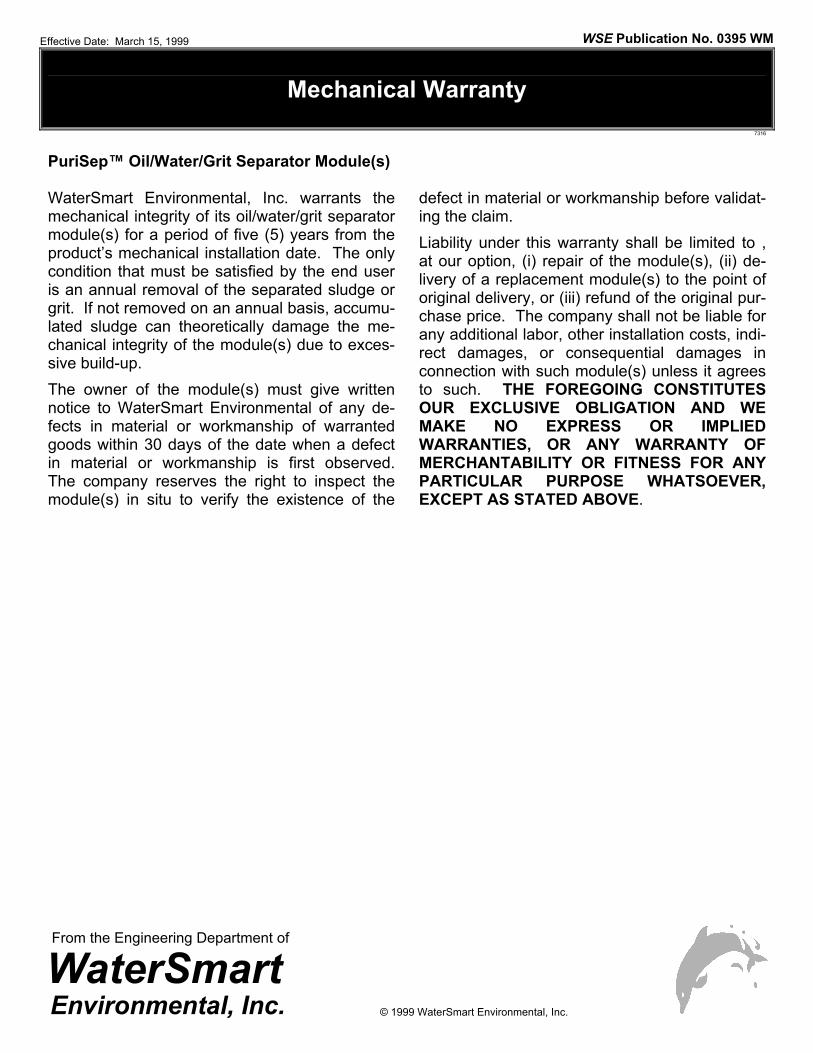
PuriSep™ Oil/Water/Grit Separator Module(s) WaterSmart Environmental, Inc. warrants the mechanical integrity of its oil/water/grit separator module(s) for a period of five (5) years from the product’s mechanical installation date. The only condition that must be satisfied by the end user is an annual removal of the separated sludge or grit. If not removed on an annual basis, accumu-lated sludge can theoretically damage the me-chanical integrity of the module(s) due to exces-sive build-up. The owner of the module(s) must give written notice to WaterSmart Environmental of any de-fects in material or workmanship of warranted goods within 30 days of the date when a defect in material or workmanship is first observed. The company reserves the right to inspect the module(s) in situ to verify the existence of the
defect in material or workmanship before validat-ing the claim. Liability under this warranty shall be limited to , at our option, (i) repair of the module(s), (ii) de-livery of a replacement module(s) to the point of original delivery, or (iii) refund of the original pur-chase price. The company shall not be liable for any additional labor, other installation costs, indi-rect damages, or consequential damages in connection with such module(s) unless it agrees to such. THE FOREGOING CONSTITUTES OUR EXCLUSIVE OBLIGATION AND WE MAKE NO EXPRESS OR IMPLIED WARRANTIES, OR ANY WARRANTY OF MERCHANTABILITY OR FITNESS FOR ANY PARTICULAR PURPOSE WHATSOEVER, EXCEPT AS STATED ABOVE.
Effective Date: March 15, 1999 WSE Publication No. 0395 WM
From the Engineering Department of
© 1999 WaterSmart Environmental, Inc.
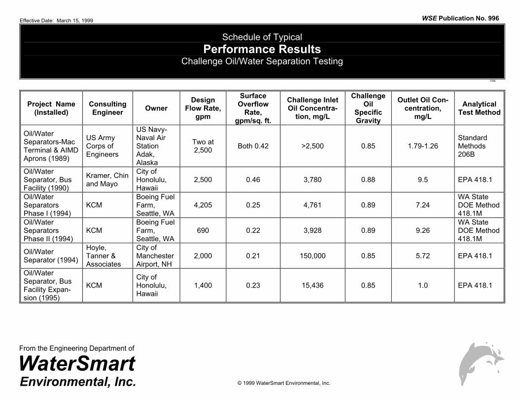
Schedule of Typical Performance Results
Challenge Oil/Water Separation Testing
7356
Project Name (Installed)
Consulting Engineer Owner
Design Flow Rate,
gpm
Surface Overflow
Rate, gpm/sq. ft.
Challenge Inlet Oil Concentra-
tion, mg/L
Challenge Oil
Specific Gravity
Outlet Oil Con-centration,
mg/L Analytical
Test Method
Oil/Water Separators-Mac Terminal & AIMD Aprons (1989)
US Army Corps of Engineers
US Navy-Naval Air Station Adak, Alaska
Two at 2,500 Both 0.42 >2,500 0.85 1.79-1.26
Standard Methods 206B
Oil/Water Separator, Bus Facility (1990)
Kramer, Chin and Mayo
City of Honolulu, Hawaii
2,500 0.46 3,780 0.88 9.5 EPA 418.1
Oil/Water Separators Phase I (1994)
KCM Boeing Fuel Farm, Seattle, WA
4,205 0.25 4,761 0.89 7.24 WA State DOE Method 418.1M
Oil/Water Separators Phase II (1994)
KCM Boeing Fuel Farm, Seattle, WA
690 0.22 3,928 0.89 9.26 WA State DOE Method 418.1M
Oil/Water Separator (1994)
Hoyle, Tanner & Associates
City of Manchester Airport, NH
2,000 0.21 150,000 0.85 5.72 EPA 418.1
Oil/Water Separator, Bus Facility Expan-sion (1995)
KCM City of Honolulu, Hawaii
1,400 0.23 15,436 0.85 1.0 EPA 418.1
Effective Date: March 15, 1999 WSE Publication No. 996
© 1999 WaterSmart Environmental, Inc.
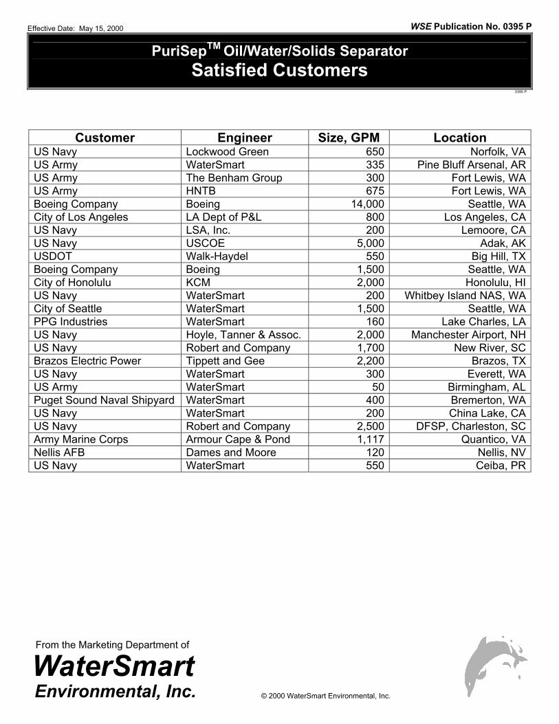
PuriSepTM Oil/Water/Solids Separator Satisfied Customers
0395 P
Customer Engineer Size, GPM Location
US Navy Lockwood Green 650 Norfolk, VAUS Army WaterSmart 335 Pine Bluff Arsenal, ARUS Army The Benham Group 300 Fort Lewis, WAUS Army HNTB 675 Fort Lewis, WABoeing Company Boeing 14,000 Seattle, WACity of Los Angeles LA Dept of P&L 800 Los Angeles, CAUS Navy LSA, Inc. 200 Lemoore, CAUS Navy USCOE 5,000 Adak, AKUSDOT Walk-Haydel 550 Big Hill, TXBoeing Company Boeing 1,500 Seattle, WACity of Honolulu KCM 2,000 Honolulu, HIUS Navy WaterSmart 200 Whitbey Island NAS, WACity of Seattle WaterSmart 1,500 Seattle, WAPPG Industries WaterSmart 160 Lake Charles, LAUS Navy Hoyle, Tanner & Assoc. 2,000 Manchester Airport, NHUS Navy Robert and Company 1,700 New River, SCBrazos Electric Power Tippett and Gee 2,200 Brazos, TXUS Navy WaterSmart 300 Everett, WAUS Army WaterSmart 50 Birmingham, ALPuget Sound Naval Shipyard WaterSmart 400 Bremerton, WAUS Navy WaterSmart 200 China Lake, CAUS Navy Robert and Company 2,500 DFSP, Charleston, SCArmy Marine Corps Armour Cape & Pond 1,117 Quantico, VANellis AFB Dames and Moore 120 Nellis, NVUS Navy WaterSmart 550 Ceiba, PR
Effective Date: May 15, 2000 WSE Publication No. 0395 P
From the Marketing Department of
© 2000 WaterSmart Environmental, Inc.