PENERAPAN BIOMEKANIKA, RESPONS DAN ADAPTASI OTOT RANGKA.pptx

February 10, 2020 Urbantech File No. 06-233ph2
Tony Dulisse, CET Transportation and Development Technologist Infrastructure Services Town of Orangeville 87 Broadway Orangeville, ON, L9W 1K1
Re: Response to 3nd Engineering Submission Comments (in support of Draft Plan approval) Orangeville Highlands Phase 2 Town File No.: 51/10 & OPZ 5/10
We have reviewed the comments provided by Transportation and Development, dated January 27, 2020, on the 3rd submission of the Functional Servicing & Stormwater Management Report
When Urbantech prepared the FSR and GSAI prepared the Draft Plan of Subdivision, there were some notable issues with the road alignment. Specifically, the “kink” in the road on the northern leg of Street C. We asked that the applicant revisit the configuration to remove the horizontal sag. In our opinion removing the horizontal sag improves driver safety. The next submission should address the issue and the plan(s) revised accordingly;
Please refer to the revised Draft Plan (Attachment 1) illustrating a revised alignment for the “kink” in Street C. The revised alignment can be achieved without impacting the number of lots and is in conformance with the engineering design criteria provided by T&D following their 1st submission review (minimum centerline radius = 120m). We request that T&D defer further review to the detailed design stage when more detail can be provided.
Crescent corners were requested on 3 corners of Street C. The applicant has not provided the required crescent corners. Revise the plan to reflect that requirement. The radii on the corners can be the same as those used in the first phase of this development and the subdivision to the south.
Please refer to Attachment 2 for a sample from Phase 1. In this case, the crescent corner was achieved within a 15m wide right-of-way without impacting the draft plan. Accordingly, the requested crescent corners will also be able to be achieved on Street ‘C’ which is an 18.5m wide right-of-way. As this does not impact the draft plan, we request that T&D defer further review to the detailed design stage when more detail can be provided for context, including detailed grading plans.
P:\Projects\06-233-Phase 2\Correspondence\Letters\FSR\Response to 3rd Sub Comments\20-02-10-SR-Response to 3rd Page 1 of 5 Submission Comments (Town).docx
Urbantech® Consulting, A Division of Leighton-Zec Ltd. 3760 14th Avenue, Suite 301 Markham, Ontario L3R 3T7
TEL: 905.946.9461 FAX: 905.946.9595 www.urbantech.com

Cont’d…
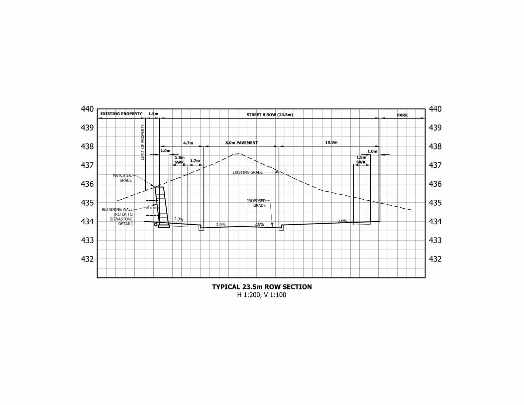
Street B connects with Hansen opposite Amelia Street. The current draft plan shows that there will be work outside of the proposed plan. When the abutting subdivision was approved in the late 1980’s the property was conveyed to the Town. The purpose of the conveyance to the Municipality was for the extension of the existing road and transportation network. The applicant is proposing to construct the road and connect in accordance with the Official Plan. Given the topography, the requirement for a 1.8m wide sidewalk on both sides of the road, proposed lane configurations and geometry to match existing, the applicant will need to demonstrate that the proposed 23m wide right‐of‐way is adequate to safely accommodate the design and ultimate construction. Provide scaled cross‐sections in support of the proposal.
The right-of-way width is 23.5m as indicated on the Draft Plan and preliminary engineering drawings. Refer to Attachment 3 for a typical ROW cross section, as requested. Note that we have illustrated the worst case scenario which occurs right at Hansen Boulevard - due to space constraints with the existing property and the requirement to align the pavement centerline with existing Amelia Street to the south, the 23.5m ROW is asymmetrical with a western boulevard width of 4.7m and an eastern boulevard of 10.8m.
Both intersections into the development will be signalized in accordance with the traffic impact study. The calculations for site line requirements have not been provided. Please provide the required calculations indicating that proper site distance and visibility triangle has been provided for stop controlled intersections. Refer to the TAC Manual Section 2.3.3.5, copy attached.
Please refer to Attachment 4 for a detailed sight-line analysis prepared by Paradigm.
In addition to Bullet 3 above, the applicant is proposing to construct a retaining wall to over‐come the physical constraints and changing elevations on the west side of the intersection abutting the existing properties. Include the retaining wall and a brief summary of how that structure will be constructed against the existing residences relative to the right‐of‐way. We appreciate that these are construction details that will be addressed during the design review stage of the development. However, there are some concerns as it relates to the constructability of all required features in the amount of ROW being proposed. All other retaining walls being proposed are to be located on private property.
As the height of the wall varies to nearly 3m, drawings prepared by a licensed structural engineer will be required for approval and construction. However, to facilitate draft plan approval we have provided a conceptual design illustrating how the proposed wall could potentially fit within the 23.5m wide right-of-way plus adjacent 1.5m wide block adjacent to the existing property and be constructed without encroachment onto the adjacent properties. Refer to Attachments 3 and 5 for details. Depending on the length of the geogrid (i.e. tiebacks) required, the face of the wall may need to be adjacent to the sidewalk (currently 0.2m of separation is shown which still allows a separation of 1.2m from the face of the sidewalk to the back-of-curb).
Urbantech Consulting Page 2 of 5

Cont’d…
We generally agree that retaining walls, where required to support private development (i.e. medium density blocks) should be located on private property and confirm that further details will be provided at detailed design. However, we disagree that the retaining wall required to facilitate the norther trail connection Brucedale Boulevard should be on the private lot since the wall is only required due to the walkway’s grading constraints, not the private lot’s grading. Accordingly, the wall should be owned and maintained by the Town as part of their walkway block/trail system.
The outlet from the SWMP is designed to flow northward and outlet to the north branch of the Middle Monora Creek. The access road along that area is to be designed and constructed wide enough to allow service vehicles and equipment to access the area for regular inspections and maintenance. Ensure that the access is a minimum of 4 metres wide and a turn around feature added for safety. Update the plans accordingly and confirm that this design feature can be accommodated within the proposed blocks designated for stormwater management.
The outlet being referred to is known as Drainage Feature ‘B’; while this feature is the proposed discharge location for the SWM facility, it does not contain any structures, spillways etc. that would require maintenance. The feature is also intended to provide a habitat for amphibians (refer to EIS) so any disturbance should be avoided.
A 2m shelf has been provided to allow the Town to access Drainage Feature ‘B’ by foot or with small construction equipment. There is also a 10m buffer along the western side of the feature – if, for whatever reason, large construction equipment is required to access the area in the future, this buffer would provide adequate space. However, a 4m wide access and turnaround cannot be provided in the available space without significantly impacting the existing conditions. We further note that most existing features (i.e. Monora Creek) would not be provided with maintenance access or turnarounds as part of a subdivision design.
The FSR indicates that road grades will range between 0.5% and 5%. Town of Orangeville standards require that road grades range from a minimum of 0 .75% (1% around crescent corners and cul‐de‐sacs) to 6% with 5% the preferred maximum. Update the FSR accordingly.
Although the FSR text states 0.5%, all road centerline grades shown on Figure 2, “Preliminary Grading Plan and Overland Flow Route,” are 1.0% or greater. Therefore, we can confirm that the Town’s requested minimum grade of 1.0% can be achieved throughout the site. Regardless, this comment does not impact the draft plan and should be deferred to the detailed design stage.
Although minor, indicate that the minimum grades on the lots within the swales shall be 2% and the maximum 5%. The lots are also required to have a “flat table area” of 5 metres with a maximum grade of 5% in elevation change. Review the design and confirm that this design feature can be accommodated.
This comment does not impact the draft plan and should be deferred to detailed design. However, we confirm that all swales, as indicated on Figure 2, “Preliminary Grading Plan and
Urbantech Consulting Page 3 of 5

Cont’d…
Overland Flow Route,” shall be graded between 2% and 5% slope and that a minimum of 5m “flat” space shall be provided at the rear of all units.
A sediment removal drying area has been added to the SWMP block. The applicant has provided an area 20m x 10m. Please indicate how this area was arrived at and what parameters were used to determine the appropriate area.
Further detail will be provided in the SWM Report and Operations & Maintenance Manual submitted at the detailed design stage. However, for the purposes of draft plan approval, we provide the following information to support the sizing of the pond block.
Table 6.3: Annual Sediment Loadings (MOE SWM Planning & Design Manual, 2003)
Catchment Imperviousness
Annual Loading (kg/ha)
Wet Density (kg/m³)
Annual Loading (m³/ha)
35% 770 1,230 0.6
55% 2,300 1,230 1.9
70% 3,495 1,230 2.8
85% 4,680 1,230 3.8
Site Imperviousness = 70%, therefore annual loading = 2.8m3/ha/year Drainage to SWM Pond = 10.28ha, therefore annual loading = 28.8m3/year
Provided sediment drying area = 20m x 10m = 200m2
If the pond will be cleaned by mechanical dredging, the provided drying area would allow a significant amount of material to be temporarily stored (the height of the pile could vary based on soil characteristics). However, the 20x10m area would also provide adequate space for a vacuum operation setup, which is becoming an increasingly common method for pond cleaning. Several ponds we have recently designed in Brampton have been cleaned using this approach with smaller sediment drying areas than what is proposed for the subject site.
Urbantech Consulting Page 4 of 5

Cont’d…
We trust the enclosed information is satisfactory for your review and clearance for draft plan approval. We request that any further details required for approval be deferred to detailed design. Please contact our office directly with any questions or if you require additional information.
Regards,
Scott Riemer, P.Eng. Senior Project Manager
cc: Brandon Ward, Town of Orangeville Carmen Jandu, Ventawood Management Roberta Harvey, Country Green Homes
Attachments: Attachment 1 – Revised Draft Plan by GSAI Attachment 2 – Crescent Corner Sample Attachment 3 – Proposed 23.5m ROW Cross Section Attachment 4 – Sight Line Analysis by Paradigm Attachment 5 – Typical Retaining Wall Detail
Urbantech Consulting Page 5 of 5

Regional Floodline
Toe of Slope
Calculated Stable
Slope
10m Erosion
Access Allowance
SUBJECT
LANDS
KEY PLAN
DRAFT PLAN OF SUBDIVISION
ORANGEVILLE HIGHLANDS LIMITED &
BRUCEDALE INVESTMENTS INC.
FILES: OPZ 5/10 & S 1/10
PART OF LOT 3,
CONCESSION 2 W.H.S.,
TOWN OF ORANGEVILLE
DUFFERIN COUNTY
OWNERS CERTIFICATE
I HEREBY AUTHORIZE GLEN SCHNARR & ASSOCIATES INC. TO PREPARE AND SUBMIT
THIS DRAFT PLAN OF SUBDIVISION TO THE TOWN OF ORANGEVILLE FOR APPROVAL.
BRUCEDALE INVESTMENTS INC.
SIGNED __________________ DATE ______________________________
OCT. 17, 2017
JOHN G. NESBITT, GILBERT L. BOLAND,
PRESIDENT DIRECTOR
ORANGEVILLE HIGHLANDS LIMITED
OCT. 17, 2017
GILBERT L. BOLAND, JOHN G. NESBITT,
PRESIDENT SECRETARY
SIGNED __________________ __________________ DATE ____________
SURVEYORS CERTIFICATE
I HEREBY CERTIFY THAT THE BOUNDARIES OF THE LANDS TO BE SUBDIVIDED AS
SHOWN ON THIS PLAN AND THEIR RELATIONSHIP TO ADJACENT LANDS ARE
CORRECTLY AND ACCURATELY SHOWN.
SEPT. 28, 2017
THOMAS SALB, O.L.S.
JD BARNES LIMITED
401 WHEELABRATOR WAY, SUITE A
MILTON, ONTARIO L9T 3C1
SIGNED _________________________ DATE ____________
ADDITIONAL INFORMATION
(UNDER SECTION 51(17) OF THE PLANNING ACT) INFORMATION REQUIRED BY CLAUSES
A,B,C,D,E,F,G,J & L ARE SHOWN ON THE DRAFT AND KEY PLANS.
H) MUNICIPAL AND PIPED WATER TO BE PROVIDED
I) SANDY LOAM AND CLAY LOAM
K) SANITARY AND STORM SEWERS TO BE PROVIDED
LAND USE SCHEDULE
LAND USE BLOCKS
AREA
(ha)
AREA
(ac)
UNITS
TOWNHOUSE (STREET) - 5.5m (18')
1-17 1.71 4.23 93
TOWNHOUSE (BACK TO BACK) - 7.0m (23') 18,19 0.29 0.72 26
TOWNHOUSE (CONDOMINIUM STACKED) 20,21 1.22 3.01 88
APARTMENTS 22,23
2.85 7.04 334
PARK 24,25
2.10 5.19
SWM POND 26 1.24 3.06
OPEN SPACE (WALKWAY)
27 0.02 0.05
NATURAL HERITAGE SYSTEM & BUFFER (NHS)
28 6.24 15.42
18.5m ROW (615m)
1.15 2.84
20.0m - 23.5m ROW (561m)
1.13 2.79
TOTAL 28 17.95 44.36 541
NOTES
-
Streets A / B & Hansen Blvd. intersection daylight triangles = 7.5m x 7.5m
-
All other daylight triangles are 6m x 6m
-
Pavement Illustration is diagrammatic only
-
Natural Heritage System constraint information provided by Urbantech April, 2019
Scale 1:1000
(24 x 36)
February 7, 2020

432
433
434
435
436
437
438
439
440
432
433
434
435
436
437
438
439
440
STREET B ROW (23.5m)
1.0m
10.8m
1.8m
SWK.
8.0m PAVEMENT
1.0m
4.7m
1.8m
SWK.
1.5m
2.0%
2.0
%
2.0
%
2.0
%
RETAINING WALL
(REFER TO
SIENASTONE
DETAIL)
PROPOSED
GRADE
EXISTING GRADE
MATCH EX.
GRADE
LIM
IT O
F PRO
PERTY
EXISTING PROPERTY
PARK
TYPICAL 23.5m ROW SECTION
H 1:200, V 1:100
1.7m

5A-150 Pinebush Road Cambridge ON N1R 8J8
p: 519.896.3163 905.381.2229 416.479.9684
www.ptsl.com
06 February 2020 Project: 190549
Carmen N. Jandu, RPP Orangeville Highlands Ltd. c/o Ventawood Management Inc. 2458 Dundas Street West, Unit 9 Mississauga L5K 1R8
Dear Carmen N. Jandu:
RE: ORANGEVILLE HIGHLANDS – TOWN COMMENT RESPONSE LETTER
In April 2019, Paradigm Transportation Solutions Limited (Paradigm) prepared a letter to address peer review comments on the Transportation Impact Study (TIS) prepared in May 2018.
Since submission of the Study and Peer Review response memo, the Town of Orangeville has provided additional transportation comments. The following letter outlines our responses/clarification to the Town’s comments contained in the email dated 27 January 2020.
Comment #4:
“Both intersections into the development will be signalized in accordance with the traffic impact study. The calculations for site line requirements have not been provided. Please provide the required calculations indicating that proper site distance and visibility triangle has been provided for stop controlled intersections. Refer to the TAC Manual Section 2.3.3.5, copy attached.”
Comment #4 Response:
The Transportation Association of Canada (TAC) Geometric Design Guide for Canadian Roads referred to by the Town is the September 1999 version. The TAC Geometric Design Guide for Canadian Roads June 2017 manual is the current version and follows best practices. Based on the TAC 2017 manual1, the following sight distance requirements apply for a design speed of 10 km/h over the posted speed limit (60 km/h):
1 Transportation Association of Canada, Geometric Design Guide for Canadian Roads, 2017.

Crossing Distance: 110 metres2;
Left-Turn from Stop: 130 metres3
Right-Turn from Stop: 110 metres4
Both Street A and Street B intersections with Hansen Boulevard are existing intersections. Street A aligns with Victor Large Way and Street B aligns with Amelia Street. Traffic control signals are in operation at the Amelia Street intersection.
Attachment A contains the sight triangles for Street A and Street B based on TAC Geometric Design Guide for Canadian Roads June 2017.
The sight triangles for Street A and Street B are contained within the existing Hansen Boulevard right-of-way. The proposed daylight triangles to the Street A and Street B approaches are satisfactory. No changes to the block layout are recommended.
We trust that this information is responsive to the comments that were raised by the Town of Orangeville. If you should have any questions or would like to discuss our response in more detail, please feel free to contact us.
Yours very truly,
PARADIGM TRANSPORTATION SOLUTIONS LIMITED
Scott Catton, C.E.T. Stew Elkins, B.E.S. Senior Project Manager Vice President
2 Ibid. Table 9.9.6: Design Intersection Sight Distance – Case B2, Right Turn from Stop, and Case B3, Crossing Maneuver 3 Ibid. Table 9.9.4: Design Intersection Sight Distance – Case B1, Left Turn from Stop 4 Ibid. Table 9.9.6: Design Intersection Sight Distance – Case B2, Right Turn from Stop, and Case B3, Crossing Maneuver
Paradigm Transportation Solutions Limited | Page 2

Attachment A
Sight Triangles
Paradigm Transportation Solutions Limited | Page 3

FS
R u
nder
lay
Red
uced
sca
le d
raw
ing.
Do
not
scal
e
TAC
201
7 Si
ght D
istan
ceHa
nsen
Bou
leva
rd &
Stre
et A
C
ross
ing
Man
euve
r O
rang
eville
Hig
hla
nds
Sigh
t Tria
ngle
s Fi
gure
119
0549

FS
R u
nder
lay
Red
uced
sca
le d
raw
ing.
Do
not
scal
e
TAC
201
7 Si
ght D
istan
ceHa
nsen
Bou
leva
rd &
Stre
et A
Le
ft-Tu
rn F
rom
Sto
p O
rang
eville
Hig
hla
nds
Sigh
t Tria
ngle
s Fi
gure
219
0549

FS
R u
nder
lay
Red
uced
sca
le d
raw
ing.
Do
not
scal
e
TAC
201
7 Si
ght D
istan
ceHa
nsen
Bou
leva
rd &
Stre
et A
Ri
ght-
Turn
Fro
m S
top
Ora
ngev
ille H
ighl
and
s Si
ght T
riang
les
Figu
re 3
1905
49

FS
R u
nder
lay
Red
uced
sca
le d
raw
ing.
Do
not
scal
e
TAC
201
7 Si
ght D
istan
ceHa
nsen
Bou
leva
rd &
Stre
et B
C
ross
ing
Man
euve
r O
rang
eville
Hig
hla
nds
Sigh
t Tria
ngle
s Fi
gure
419
0549

FS
R u
nder
lay
Red
uced
sca
le d
raw
ing.
Do
not
scal
e
TAC
201
7 Si
ght D
istan
ceHa
nsen
Bou
leva
rd &
Stre
et B
Le
ft-Tu
rn F
rom
Sto
p O
rang
eville
Hig
hla
nds
Sigh
t Tria
ngle
s Fi
gure
519
0549

FS
R u
nder
lay
Red
uced
sca
le d
raw
ing.
Do
not
scal
e
TAC
201
7 Si
ght D
istan
ceHa
nsen
Bou
leva
rd &
Stre
et B
Ri
ght-
Turn
Fro
m S
top
Ora
ngev
ille H
ighl
and
s Si
ght T
riang
les
Figu
re 6
1905
49

TYPICAL SECTION - NOT FOR CONSTRUCTION
SienaStone
Coping Unit
SienaStone
Standard Unit
Retained
Geogrid Length: 2.2m [7.3 ft]
Infill Soil
Soil
Perforated Drain
with Filter Sock
[conn. to positive outlet]
Foundation
Soil
Compacted
Granular Base
Filter Cloth
Design Specific Geometric Information
Retaining Wall Geogrid Type
See Notes
SienaStone w/ Geogrid
System and Manufacturer
Minimum
Maximum Height
Geogrid LTDS
See Notes2780 (109)
mm (in)
kN/m (lb/ft)
Maximum Slope Maximum Slope
None
1V:3H
Above Wall Below Wall
Max. Surcharge Depth of
Above Wall Embedment 277 (11)
kPa (lb/sq.ft)
None
mm (in)
Compacted
Batter
Base Dimension
879 x 186 (35 x 7)
7.12
of Wall
mm (in)
Design Specific Soil Information
Soil Region
Infill Retained Foundation Base Drainage
CL CLGW GW
Well graded, free
Description
see infill
Inorganic Clays Inorganic Clays Well graded, free
(by USCS)
draining Granular Low Plasticity Low Plasticity draining Granular
Effective
Internal Friction 35 28 28 39 NR
Angle
Moist Unit
Weight 22 (140) 20 (127) 20 (127) 22 (140) NR
kN/cu.m (lb/cu.ft)
Effective
Cohesion
NR NR NR NR NR
kPa (lb/sq.ft)
Placed in 150mm Undisturbed Allowable bearing Crushed Gravel Gravel infill must
Notes
Soil
(6") lifts and dense soil or be well graded,
compacted to 95 %
cap.must exceed (free draining)
well compacted 100kPa (2100 psf) compacted to 98 % angular, free drain
SPD. Eng. fill.
SPD. w/max. 8% fines
NR - Not Required
Notes:
1. This design meets or exceeds the minimum factors of safety required by Risi Stone Systems based on the design
parameters listed above. The analysis was performed as outlined in the National Concrete Masonry Association
Design Manual for Segmental Retaining Walls, Third Edition. This is a typical, non site-specific Design.
2. No analysis of global stability, total or differential settlement, or seismic effects has been performed.
3. This design is only provided to illustrate the general arrangement of the SRW structure for preliminary costing and
feasibility purposes only. This drawing is not for construction. A qualified Engineer must be retained to provide the
Final Design prior to construction.
4. Structures such as handrails, guardrails, fences, terraces, and site conditions such as water applications, drainage
and soil conditions, additional live and dead loads, etc., have significant effects on the wall design and have not been
taken into account in this typical section. When accounted for in the Final Design, other conditions and elements may
result in additional design measures (geogrid, drainage, etc) and cost.
5. For geogrid reinforced structures, a minimum Long Term Allowable Design Strength of 14 kN/m was assumed.
Contact your manufacturer or Risi Stone Systems for a list of approved geogrid reinforcements.
SienaStone
Retaining Wall
RisiStone
retaining wall systems Geogrid Section
2780mm (9.11ft)
Site: 3H:1V Slope - Clays
Infill: Granular
SS2RBSAI278www.risistone.com
1-800-626-9255