ENGINEERING AND TECHNOLOGY TECHNOLOGY … · System Specification for a Train Tracking and Data...
14
BBC2655 Version 1 14 Page 1 of A division of Transnet limited ENGINEERING AND TECHNOLOGY TECHNOLOGY MANAGEMENT SPECIFICATION SPOORNET LOCOMOTIVE TRAIN DEFINITION UNIT Author Engineer Technology Management N.M.X Gobhozi ……………………………. . Checked Manager Office of the CIO R Oosthuizen …………………………... Authorised Principal Engineer Technology Management Dr. B.M. Steyn …………………………... Date September 2006 Circulation restricted to: Technology Management Office of the CIO Relevant 3 rd parties © This document as a whole is protected by copyright. The information herein is the sole property of Transnet Ltd. It may not be used, disclosed or reproduced in part or in whole in any manner whatsoever, except with the written permission of and in a manner permitted by the proprietors. “PRIEVIEW COPY ONLY”
Transcript of ENGINEERING AND TECHNOLOGY TECHNOLOGY … · System Specification for a Train Tracking and Data...

BBC2655 Version 1
14Page 1 of
A division of Transnet limited
ENGINEERING AND TECHNOLOGY
TECHNOLOGY MANAGEMENT
SPECIFICATION
SPOORNET LOCOMOTIVE TRAIN DEFINITION UNIT
Author Engineer
Technology Management
N.M.X Gobhozi
……………………………..
Checked Manager
Office of the CIO
R Oosthuizen
…………………………...
Authorised Principal Engineer
Technology Management
Dr. B.M. Steyn
…………………………...
Date September 2006
Circulation restricted to:
Technology Management
Office of the CIO
Relevant 3rd parties
© This document as a whole is protected by copyright. The information herein is the sole property of Transnet Ltd. It may not be used, disclosed or reproduced in part or in whole in any manner whatsoever, except with the written permission of and in a manner permitted
by the proprietors.
“PRIEVIEW COPY ONLY”

BBC2655 Version 1
Page 2 of 14
TABLE OF CONTENTS
1 SCOPE ...........................................................................................................................................................3 1.1 IDENTIFICATION.......................................................................................................................................3
1.2 SYSTEM OVERVIEW .................................................................................................................................3
2 DOCUMENT OVERVIEW ..............................................................................................................................4 2.1 APPLICABLE DOCUMENTS...............................................................................................................4
3 REQUIREMENTS...........................................................................................................................................5 3.1 SYSTEM REQUIREMENTS..........................................................................................................................5
3.2 EXTERNAL INTERFACES...........................................................................................................................7
3.3 MAJOR COMPONENT REQUIREMENTS ......................................................................................................7
4 SPOORNET SUPPLIED PROPERTY LIST...................................................................................................9 5 SPOORNET LOANED PROPERTY LIST .....................................................................................................9 6 SYSTEM CHARACTERISTICS .....................................................................................................................9
6.1 SYSTEM AVAILABILITY FACTORS ..............................................................................................................9
6.2 ENVIRONMENTAL CONDITIONS .................................................................................................................9
6.3 PORTABILITY ..........................................................................................................................................9
6.4 TRANSPORTABILITY ..............................................................................................................................10
6.5 FAIL-SAFETY REQUIREMENTS ................................................................................................................10
6.6 FLEXIBILITY AND EXPANSION .................................................................................................................10
7 PERFORMANCE CHARACTERISTICS......................................................................................................10 8 PHYSICAL CHARACTERISTICS................................................................................................................10 9 GENERAL REQUIREMENTS......................................................................................................................10
9.1 DESIGN AND CONSTRUCTION .................................................................................................................10
9.2 DOCUMENTATION..................................................................................................................................11
9.3 LOGISTICS ............................................................................................................................................11
9.4 PERSONNEL AND TRAINING....................................................................................................................12
9.5 PHYSICAL DIMENSIONS .........................................................................................................................12
10 CONDITIONS.............................................................................................................................................12 11 QUALITY ASSURANCE............................................................................................................................12
11.1 RESPONSIBILITY FOR TESTS ................................................................................................................12
11.2 TESTS AND EXAMINATIONS ..................................................................................................................12
12 GLOSSARY ...............................................................................................................................................14
“PRIEVIEW COPY ONLY”
BBC2655 Version 1
Page 3 of 14
1 SCOPE 1.1 Identification
The development design and delivery of a train number input module. This document presents the requirements of the Train definition unit required by Spoornet.
1.2 System overview
It is critical to operations at Spoornet that all locomotive data communications are indexed with a Spoornet allocated train identification number. This train number is a unique reference to a train movement as well as its locomotives and wagons consist. This number is issued to a train driver at the beginning of a train trip for purposes of identification for communications and authorizations.
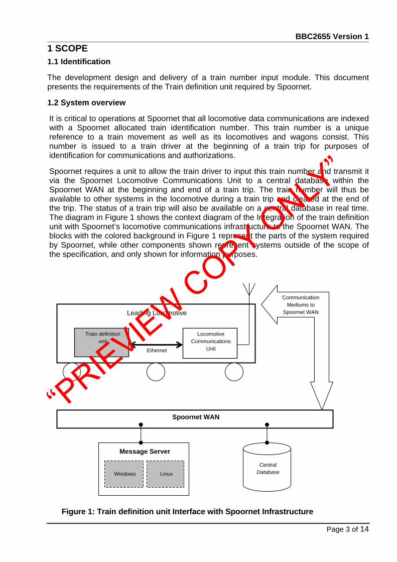
Spoornet requires a unit to allow the train driver to input this train number and transmit it via the Spoornet Locomotive Communications Unit to a central database within the Spoornet WAN at the beginning and end of a train trip. The train number will thus be available to other systems in the locomotive during a train trip and cleared at the end of the trip. The status of a train trip will also be available on a central database in real time. The diagram in Figure 1 shows the context diagram of the Integration of the train definition unit with Spoornet’s locomotive communications infrastructure to the Spoornet WAN. The blocks with the colored background in Figure 1 represent the parts of the system required by Spoornet, while other components shown represent systems outside of the scope of the specification, and only shown for information purposes.
Figure 1: Train definition unit Interface with Spoornet Infrastructure
Leading Locomotive
Locomotive Communications
Unit
Train definition unit
Ethernet
Communication Mediums to
Spoornet WAN
Spoornet WAN
Message Server
Central Database
Linux
Windows
“PRIEVIEW COPY ONLY”

BBC2655 Version 1
Page 4 of 14
Figure 2 shows in more detail the multiple components that form part of the Train Definition Unit (TDU).
Train Definition Unit
Ruggedized Day/Night
Alphanumeric Display Window
Figure 2: Train definition unit components
Ruggedized Alphanumeric Input
Keypad
The communication infrastructure that Spoornet employs entails a TCP/IP Local Area Network (LAN) on each locomotive. This network is connected to the Spoornet Wide Area Network (WAN) using various data communications options. The communication units employed in Spoornet locomotives connect the locomotive network to the Spoornet network with GPRS, WiFi and UHF Radio.
The communications mediums connect directly to the Spoornet WAN or through multiple land-based access points at various control centers in the country under the control of the Train Control Officers (TCOs). Information such as date-time stamp, GPS coordinates and locomotive identification number is broadcast on all the Ethernet ports of the communication units or made available on request. The information is broadcast in the form of TCP/IP and UDP/IP packets.
Two servers on the Spoornet WAN are available to execute the supplier messaging software, and are either a Linux, or Microsoft based server.
The Train definition units shall employ the Power Over Ethernet interface for its power requirements.
2 DOCUMENT OVERVIEW 2.1 APPLICABLE DOCUMENTS
The following specifications, standards and drawings of the exact issue form a part of this specification to the extent shown herein. In the event of conflict between the referenced document and this specification, the contents of this specification shall be considered a superseding requirement.
10/100 Mbps Ethernet Port Controller with Power Over
Ethernet (POE)
Controller
PSU
(POE)
10100110
10100110
10100110
VDC
“PRIEVIEW COPY ONLY”

BBC2655 Version 1
Page 5 of 14
2.1.1 Transnet documents
CSE-1159-001 CAT E48 Standard specification for documentation for signals equipment.
Cenelec EN50155 Railway Applications: Electronic equipment used on Rolling Stock
IEC 60571 Electronic equipment used on rail vehicles
Cenelec EN 50121-3-2 Railway Applications: Electromagnetic compatibility, Rolling stock apparatus.
BBB0947 (Latest issue) General Ergonomic Guideline for the Design of Visual Display Man – Machine - Interfaces
CSE-1154-001 CAT E48 Environmental specification of SPOORNET railway signalling systems.
BBC1789 System Specification for a Train Tracking and Data Communication System (TRITON)
IEC 61373 Railway applications. Rolling stock equipment. Shock and vibration tests
3 REQUIREMENTS 3.1 System requirements
3.1.1 The unit shall contain a ruggedized alphanumeric input keypad with no more than 16 input keys.
3.1.2 The unit shall contain a ruggedized display window that can display a minimum of 16 alphanumeric characters on a single line in both daylight and nighttime.
3.1.3 The unit shall be powered with a Power Over Ethernet interface from the Locomotive Communications System.
3.1.4 The unit shall obtain an IP address and a DNS name from the locomotive communications system. The train definition unit shall adhere to all relevant communication security requirements stated in BBC 1789. It should be clear that the locomotive communications controller is an enhanced hub that allocates IP addresses and provides a messaging service only. The TDU should not violate any security protocols, else it will degrade the functionality of the locomotive communications controller or not be compatible with it.
3.1.5 The train definition unit shall allow for a simple installation on a flat metal surface.
3.1.6 The train definition unit shall have the following operational functions as a minimum requirement:
3.1.6.1 When the system is switched on it shall prompt the user to input their Employee number.
“PRIEVIEW COPY ONLY”

BBC2655 Version 1
Page 6 of 14
3.1.6.2 The user shall be able to delete and correct an input at any point if an error is made during the process.
3.1.6.3 When the user has keyed in their Employee number, he/she shall be able to press a button to proceed or cancel the session
3.1.6.4 If the user proceeds, the system shall then prompt them to input the 16-character train number.
3.1.6.5 If the length and structure of the train number is correct, it shall then provide the user the options to send the information or cancel the session.
3.1.6.6 If the length or structure of the train number is incorrect, the user shall be prompted to input it again.
3.1.6.7 Cancelling the session shall return the driver to the login prompt.
3.1.6.8 If the user chooses to send the information then the system shall first request or read from the locomotive communications unit the broadcast packets for the date-timestamp and locomotive identification number.
3.1.6.9 The train definition unit shall then transmit the train number and driver information with the locomotive number and date-timestamp. via the Locomotive Communications unit in a Spoornet defined protocol to a database/ listening application running on a server in the Spoornet WAN.
3.1.6.10 When the train reaches its final destination, the driver shall be able to press a button to send a message that the train trip has come to the end, which will then clear the train number from the unit’s memory and return the program to the login state for the next train trip.
3.1.7 The information transmitted from the train definition unit shall be received by a software application running on the Message Server.
3.1.8 This information shall then be formatted correctly and used to populate a central database.
3.1.9 The train definition unit’s components shall be modular in order to improve its maintainability.
3.1.10 The unit shall have a diagnostic procedure that will cause it to test all its components and display the status of each. The unit shall be able to run checks on its I/O components and display a status OK or Fail at a command from a technician. This will particularly be useful for checks during the installation of the unit.
“PRIEVIEW COPY ONLY”

BBC2655 Version 1
Page 7 of 14
3.2 External Interfaces
The system layout described in Figure 1 illustrates the system integration and its interfaces to the locomotive communication system and the Spoornet infrastructure.
3.2.1 Interface between Train definition unit and Locomotive Communication Unit
3.2.1.1 The train definition unit shall interface to the Locomotive Communications Unit with a 10/100Mbps and Power Over Ethernet compatible Ethernet connection.
3.2.1.2 All connectors shall be packaged in such a way not to be accessible to normal working staff, e.g. train drivers etc.
3.2.1.3 Detailed information of all data that is broadcast on the ports of the communications unit is presented in Spoornet’s document BBC1789.
3.2.2 Interface between the Train Driver and Train definition unit
3.2.2.1 The train definition unit shall be physically compact, robust and easily mountable in the locomotive cab e.g. can be mounted with two screws.
3.2.2.2 It shall provide an effective interface to the driver and ease the task of information input.
3.2.2.3 Light emitting from the display shall be adjustable for easy viewing by the driver during night and daytime conditions.
3.3 Major Component Requirements
3.3.1 Train Definition Unit Display Window
3.3.1.1 The unit display window shall display all inputs made on the keypad and display any other information passed to it.
3.3.1.2 The unit display window shall be able to display a minimum of 16 alphanumeric characters on a single horizontal line.
3.3.1.3 The layout and display of the user instructions shall be clear and precise.
3.3.1.4 The information on the display window shall be equally legible in daylight and nighttime.
3.3.1.5 The display window shall be shock resistant and easy to clean.
3.3.2 Alphanumeric Keypad
3.3.2.1 The unit’s keypad shall allow for the input of all alphabet letters and decimal numbers.
“PRIEVIEW COPY ONLY”

BBC2655 Version 1
Page 8 of 14
3.3.2.2 The keypad shall have no more then 16 input buttons.
3.3.2.3 The keypad shall be robust and not susceptible to dust and other environmental factors.
3.3.2.4 The unit’s keypad shall enable the user to execute commands such as delete or clear display window contents and cancel or transmit information.
3.3.3 10/100Mbps Ethernet port controller with POE
3.3.3.1 The Ethernet port controller shall be compatible with a 10/100Mbps Ethernet connection to the locomotive communications unit.
3.3.3.2 The Ethernet controller shall be able to receive and transmit TCP/IP and UDP/IP packets.
3.3.3.3 The Ethernet port controller shall be compatible with Power Over Ethernet standard.
3.3.4 Train Definition Unit Controller
3.3.4.1 The train definition unit’s Controller shall control the interface between the inputs from the unit’s keypad and the outputs to the unit’s display window.
3.3.4.2 All relevant information that is broadcast on the Ethernet port from the locomotive communications unit such as the date-time stamp and the locomotive identification number shall be handled by the Controller.
3.3.4.3 The Controller shall attach the locomotive identification number and date-timestamp to all transmissions.
3.3.4.4 There shall be a protocol to enable other peripheral devices connected on the locomotive communications unit to request the train identification number from the train definition unit.
3.3.5 Power Supply Unit
3.3.5.1 A power supply unit that uses Power Over Ethernet shall power all the Train Definition Unit’s components.
3.3.6 Message Server Application
Spoornet has a Message Server that interfaces with applications running on Windows and Linux platforms. The Message Server is responsible for the routing of all communications between all locomotives and software applications that use the data from the locomotive peripheral systems.
3.3.6.1 The Train Definition system’s Message Server application shall receive all data from the train definition unit’s in all locomotives and populate a central database.
“PRIEVIEW COPY ONLY”

BBC2655 Version 1
Page 9 of 14
3.3.6.2 The central database table populated by the system’s Message Server Application shall contain as a minimum the following fields:
Train Number : 16 Digit Alphanumeric GPS/ LCU Date-time stamp
: YYYY/MM/DD HH:mm:ss
Loco 1 number : 10 Digit Alphanumeric (max) Employee Number
: Variable characters
Table 1: Train definition system database table structure
4 SPOORNET SUPPLIED PROPERTY LIST • The Locomotive Communications Unit with POE compatible Ethernet ports.
• Space to mount the Train definition unit inside the locomotive cab.
• Message Server
• The equipment must be able to withstand vibration and shock according to IEC 61373.
5 SPOORNET LOANED PROPERTY LIST Not Applicable.
6 SYSTEM CHARACTERISTICS • The units shall be completely plug and play.
• The unit’s boot up time shall be no greater than 1 second.
• The units shall be interchangeable without any problems or need to configure.
6.1 System availability factors
6.1.1 Mean time between failures for any electronic sub-system shall be more than 10 years. The contractor shall provide data to prove these figures.
6.2 Environmental conditions
6.2.1 Electromagnetic susceptibility and radiation limits of the system and all its components shall comply with Infrastructure (Signals) standard specification no. CSE-1154-001 CAT E48 for Grade A environment.
6.2.2 All electronic units installed on the locomotive shall conform to the requirements of European standard Cenelec EN50155 and Cenelec EN50121-3-2.
6.3 Portability
Not Applicable
“PRIEVIEW COPY ONLY”

BBC2655 Version 1
Page 10 of 14
6.4 Transportability
6.4.1 All electronic modules shall be such that a single technician will be able to transport and replace it in active service of the locomotive.
6.4.2 The units shall be robust and not incur any damage when transported on normal railway service roads. If a risk of damage does exist special packaging for transport purposes shall be supplied as special tools.
6.5 Fail-safety requirements
Although the system is not viewed as a fail-safe system, the mission of the system is critical in the operations of SPOORNET. Therefore the supplier shall indicate which special design techniques or redundancy are employed to make the system as fault tolerant as possible.
6.6 Flexibility and expansion
Given the rate of improvement of electronic modules and the life span of data communication products the design shall be modular. All interfacing hardware and software and communication protocols shall be made available to facilitate easy replacement of the functional units.
7 PERFORMANCE CHARACTERISTICS 7.1.1 The system shall adopt Spoornet protocols for communicating with the locomotive
communications unit.
7.1.2 The system should be easy to install and must not require any configuration at installation.
8 PHYSICAL CHARACTERISTICS 8.1.1.1 The system shall have a robust construction suitable for deployment in the
railway environment. Onboard the locomotive the units experience excessive vibration, temperature and humidity. In this respect the onboard equipment shall conform to the requirements for Grade F equipment as specified in Specification CSE-1154-001 CAT E48.
8.1.1.2 Office equipment shall conform to the requirements for Grade A equipment of specification CSE-1154-001 CAT E48.
9 GENERAL REQUIREMENTS 9.1 Design and construction
9.1.1 Materials processes and parts
All materials used in the system shall be at least industrial grade. Where possible, materials used shall be SABS approved. Parts shall be supplied with a certificate of origin. All parts shall be available from two independent manufacturers for at least five years. For critical parts where a second manufacturer cannot be found, stock to allow for production and maintenance for ten years shall be purchased.
All dimensions and bolt and nut sizes shall use the Metric standard
“PRIEVIEW COPY ONLY”

BBC2655 Version 1
Page 11 of 14
9.1.2 Reliability
Mean time between failures for any electronic sub-system shall not be less than 10 years. Contractor shall provide data, which proves these figures. Mean time to replace a faulty module shall be less than 30 minutes (actual working time only).
9.1.3 Workmanship
Suitably skilled personnel shall do installation and commissioning.
9.2 Documentation
The system and it’s sub-systems shall be fully documented in English in compliance with Infrastructure (Signals) standard specification no. CSE-1159-001 Cat. E48. The list of documents that shall be supplied and their contents is described in Standard Specification CSE-1159-001 Cat. E48. In addition to the requirements of standard specification number CSE-1159-001 Cat. E48, the technical documentation shall contain all the relevant information of the interfaces to the system. It shall include a full description of the hardware, protocols and message contents used on all interfaces. This shall be adequate to enable the technical staff of SPOORNET to be able to perform maintenance on the system.
All software used by the system to be fully documented, unless it is of the shelve software or the information deemed propriety. The software shall be supplied with the source code and all the compiling software required to produce executable system software unless it is off the shelve software. All code and compiling software shall become the property of Spoornet, unless it is of the shelve software.
9.3 Logistics
9.3.1 Maintenance
Preventative maintenance shall be reduced to the minimum. Any required preventative maintenance shall be clearly defined in the maintenance documentation. Preventative maintenance locomotive and office equipment shall not be required more than once in six months. During preventative maintenance, any component on site shall not require more than 30 minutes of work, averaged over the whole installation for one maintenance cycle.
An Engineering Technician shall execute first line maintenance with specific training in the functional operation of the system at unit level. An Engineering Technician shall execute second line maintenance with specific training in the operation of the system at component level. The level of support available after installation shall be clearly indicated.
9.3.2 Supply
9.3.3 Procurement shall be through the standard TRANSNET procedures for the purchase of Railway Signalling and Rolling Stock Material. The supplier shall guarantee availability of all components of the system, as well as frequently used spares of the components, for a contractually specified period of at least 5 years. The supplier shall guarantee delivery of replacement components or spares for faulty items within 4 weeks of placement of the order. Components that are critical to the functioning of the system shall be available immediately.
“PRIEVIEW COPY ONLY”

BBC2655 Version 1
Page 12 of 14
9.3.4 Facilities and equipment
Existing facilities for storage and repair will be used.
9.4 Personnel and training
9.4.1 Personnel
Users operating the system will generally be administrative and operating staff. This staff will generally be computer-literate. Skilled technicians (T3 / S4) or semi-skilled maintainers will do first line maintenance. This staff will generally be computer-literate. Highly skilled electronics technicians will do second line maintenance. They will be computer literate. Highly skilled electronics Technicians, Technologists or an Engineer will do third line backup, including programming changes. This staff will have a high level of computer literacy.
9.4.2 Training
During commissioning the supplier shall provide hands-on training in all aspects of operation of the system to a core group.
During commissioning the supplier shall provide theoretical and practical training in all aspects of first and second line maintenance to a core group of technicians.
9.5 Physical Dimensions
9.5.1 The Train definition unit enclosure shall accommodate an appropriate mounting design to enable installation without the need to drill additional holes into the enclosure. Preference will be given to a mounting configuration, which will require the least dismantling of the unit.
10 CONDITIONS The First complete Train definition unit shall be manufactured and presented to Spoornet Technology Management (Condition Assessment Technologies section) for evaluation. Any defects or faults identified at this stage shall be amended before the manufacturing process of the remaining units continues.
11 QUALITY ASSURANCE 11.1 Responsibility for tests
The contractors shall be responsible for the execution of the tests. The minimum tests to be performed shall be those determined by mutual consent between SPOORNET and the contractor. The responsibility for proving the test results shall reside with the contractor. The contractor shall document the tests and test results in full. All tests shall be observed by SPOORNET.
11.2 Tests and examinations The contractor shall be responsible to draft an Acceptance Test Procedure (ATP) and submit this to Spoornet for Approval. The tests shall be executed according to the ATP in order to test the functionality of the complete system using a holistic approach. The tests shall trace the flow of information
“PRIEVIEW COPY ONLY”

BBC2655 Version 1
Page 13 of 14
from the various Train definition units to ensure the correctness of information throughout the system. The tests shall firstly verify correct operation under normal conditions. The tests shall then be repeated using data with known fault content to verify the operation under fault conditions.
11.2.1 Maintenance and testing
11.2.1.1 The system shall have a self-diagnostic method with the results displayed on the display window.
“PRIEVIEW COPY ONLY”

BBC2655 Version 1
Page 14 of 14
12 GLOSSARY ATP Acceptance Test Procedures GPS Global Positioning System GPRS General Packet Radio Service CTC Centralised Traffic Control TCP/IP Transmission Control Protocol/Internet Protocol TCO Train Control Officer WAN Wide Area Network Wi-Fi Wireless Fidelity LAN (TCP/IP) Local Area Network UHF Ultra High Frequency radio network
“PRIEVIEW COPY ONLY”