ENGINEERING AND MATERIAL STANDARD FOR SHELL AND TUBE HEAT ...det-mop.ir/ips/me/g-me-220.pdf ·...
29
IPS-G-ME-220(1) This Standard is the property of Iranian Ministry of Petroleum. All rights are reserved to the owner. Neither whole nor any part of this document may be disclosed to any third party, reproduced, stored in any retrieval system or transmitted in any form or by any means without the prior written consent of the Iranian Ministry of Petroleum. ENGINEERING AND MATERIAL STANDARD FOR SHELL AND TUBE HEAT EXCHANGERS FIRST EDITION MAY 2007
Transcript of ENGINEERING AND MATERIAL STANDARD FOR SHELL AND TUBE HEAT ...det-mop.ir/ips/me/g-me-220.pdf ·...
IPS-G-ME-220(1)
This Standard is the property of Iranian Ministry of Petroleum. All rights are reserved to the owner. Neither whole nor any part of this document may be disclosed to any third party, reproduced, stored in any retrieval system or transmitted in any form or by any means without the prior written consent of the Iranian Ministry of Petroleum.
ENGINEERING AND MATERIAL STANDARD
FOR
SHELL AND TUBE HEAT EXCHANGERS
FIRST EDITION
MAY 2007

May 2007
IPS-G-ME-220(1)
1
CONTENTS : PAGE No.
0. INTRODUCTION............................................................................................................................. 3 1. GENERAL ....................................................................................................................................... 4
1.1 Scope........................................................................................................................................ 4 1.2 References............................................................................................................................... 4 1.4 Conflicting Requirements ...................................................................................................... 5
SECTION 2 (F) .................................................................................................................................... 6 HEAT EXCHANGER FABRICATION TOLERANCES....................................................................... 6
F-1 EXTERNAL DIMENSION, NOZZLES AND SUPPORT LOCATIONS .................................... 6 F-3 TUBE SHEETS, PARTITIONS, COVERS AND FLANGES .................................................... 6 F-4 INTERCHANGEABLE PARTS ................................................................................................ 6
SECTION 3 (G) ................................................................................................................................... 7 GENERAL FABRICATION AND PERFORMANCE INFORMATION ................................................ 7
G-1 SHOP OPERATION................................................................................................................. 7 G-3 NAME PLATES ....................................................................................................................... 8 G-4 DRAWINGS AND ASME CODE DATA REPORTS................................................................ 8 G-5 GUARANTEES...................................................................................................................... 10 G-6 PREPARATION OF HEAT EXCHANGERS FOR SHIPMENT ............................................. 10 G-7 GENERAL CONSTRUCTION FEATURES OF TEMA STANDARD HEAT EXCHANGEARTS........................................................................................................................ 11
SECTION 4 (E).................................................................................................................................. 12 INSTALLATION, OPERATION AND MAINTENANCE .................................................................... 12
E-4 MAINTENANCE OF HEAT EXCHANGERS.......................................................................... 12 SECTION 5 (RCB) ............................................................................................................................ 13 MECHANICAL STANDARDS TEMA CLASS RCB ......................................................................... 13
RCB-1 Scope and General Requirements ................................................................................ 13 RCB-2 Tubes................................................................................................................................ 15 RCB-3 Shells and Shell Covers ................................................................................................. 16 RCB-4 Baffles and Support Plates ............................................................................................ 17 RCB-5 Floating End Construction............................................................................................. 17 RCB-6 Gaskets ............................................................................................................................ 17 RCB-7 Tubesheets ...................................................................................................................... 18 RCB-9 Channels, covers and bonnets...................................................................................... 18 RCB-10 Nozzles........................................................................................................................... 18
SECTION 7 (T) .................................................................................................................................. 20 THERMAL RELATIONS ................................................................................................................... 20

May 2007
IPS-G-ME-220(1)
2
T-1 Scope and Basic Relations.................................................................................................. 20 APPENDICES: APPENDIX A ENQUIRIES AND QUOTATIONS............................................................................ 21 APPENDIX B HEAT EXCHANGER SPECIFICATION SHEET...................................................... 22 APPENDIX C SCOPE OF INSPECTION AND TESTING .............................................................. 23 APPENDIX D MANUFACTURER’S DIMENSIONAL RECORDS.................................................. 24 Note: Only sections numbers that have been supplemented are mentioned here.
* This Appendices have been added to the edition of TEMA being supplemented by this Standard.
May 2007
IPS-G-ME-220(1)
3
0. INTRODUCTION
Shell and tube heat exchangers are designed and fabricated to the standards of the "Tubular Exchanger Manufacturing Associations (TEMA)". The TEMA Standards list three mechanical standard classes of exchanger constructions R, C and B; the classes R and C are usually considered. (class B is very similar to class C). Equipment fabricated in accordance with the requirements of class R will adequately meet the heavy duty service requirements of refinery units. However, there are numerous applications which do not require this type of construction.
Steam surface condensers shall be designed and fabricated in accordance with the standard for steam surface condensers published by the Heat Exchange Institute unless specified otherwise. They are characterized by low fouling and corrosion tendencies, requiring fouling factors not exceeding 0.00034 m2.c°/W and corrosion allowances not exceeding 3.2 mm for the unit under consideration. Such units would be considered low-maintenance items. Services falling in this category are water-to-water exchangers, air coolers and similar non-hydro-carbon applications, as well as some light duty hydrocarbon services such as light ends exchangers, offsite lube oil heaters and some tank suction heaters. For such services, class C construction should be considered. Although units fabricated to either class R or class C standards comply with all the requirements of the pertinent codes, (ASME or other national codes), class C units are designed for maximum economy and may result in a cost saving of up to 5% over class R.
This Material and Engineering Standard gives the supplement to TEMA Standard Eighth Edition 1988 "Standards of the Tubular Exchanger Manufacturers Association" with its 1990 ERRATA. For ease of reference, the clauses or sections numbering of TEMA Standard, has been used throughout this Specification with the exception of Section 1 "General" at the beginning of this Standard which is added to the TEMA Standard.
Clauses in TEMA Standard not mentioned here remain unaltered.
For the purpose of this Standard, the following definitions shall hold:
Sub. (Substitution) The TEMA Standard clause is deleted and replaced by a new clause.
Del. (Deletion) : The TEMA Standard clause is deleted without any replacement.
Add. (Addition) : A new clause with a new number is added.
Mod. (Modification) Part of the TEMA Standard clause is modified, and/or a new description and/or condition is added to that clause.
May 2007
IPS-G-ME-220(1)
4
1. GENERAL
1.1 Scope
This Standard covers the minimum requirements for design and fabrication of shell and tube heat-exchangers, based on TEMA Standard eighth edition, 1999 and its 1990 ERRATA. This Standard is supplemented to the TEMA Standard.
Deviations from this Standard or the TEMA Standard are not permitted without the prior written approval of the Company.
Such approval shall be valid only for a specific case, and shall not be construed as having general validity for wider application.(Add)
Note: This is a revised version of the standard specification for shell and tube heat exchangers, which is issued as revision (1). Revision (0) of the said standard specification is withdrawn.
1.2 References
Throughout this Standard the following dated and undated standards/codes are referred to. These referenced documents shall, to the extent specified herein, form a part of this standard. For dated references, the edition cited applies. The applicability of changes in dated references that occur after the cited date shall be mutually agreed upon by the Company and the Vendor. For undated references, the latest edition of the referenced documents (including any supplements and amendments) applies.
TEMA (TUBULAR EXCHANGER MANUFACTURING ASSOCIATION)
Eighth Edition, 1999
ASME (AMERICAN SOCIETY OF MECHANICAL ENGINEERS)
Section VIII (DIV.1) "Pressure Vessel Code"
Section II "Material Specification"
Section IX "Welding and Brazing Qualifications"
API (AMERICAN PETROLEUM INSTITUTE)
RP. 521 "Guide for Pressure and Depressuring System"
ASTM (AMERICAN SOCIETY FOR TESTING AND MATERIALS)
A-193 "Specification for Alloy Steel and Stainless Steel Bolting Materials for High Temperature Service"
A-194 "Specification for Carbon and Alloy-Steel Nuts for Bolts for High Pressure and High Temperature Service"
A-320 "Specification for Alloy-Steel Bolting Materials for Low Pressure Service"
IPS (IRANIAN PETROLEUM STANDARDS)
IPS-E-PR-771 "Engineering standard for process requirements of heat exchanging equipment"
IPS-G-ME-150 "Standard for towers, Reactors pressure Vessels and Internals"

May 2007
IPS-G-ME-220(1)
5
HEI (HEAT EXCHANGE INSTITUTE)
"Standard for Steam Surface Condensers"
NACE (NATIONAL ASSOCIATION OF CORROSION ENGINEERS)
MR-01-75/ISO 15156-1 "Sulfide Stress Cracking Resistance Material for Oil Field Equipment"(Add)
1.4 Conflicting Requirements
In case of conflict between documents relating to the inquiry or order, the following priority shall apply:
1) First Priority : The Purchase order
2) Second Priority : The data/requisition sheets and drawings referred to
3) Third Priority : This Standard Specification.
4) Fourth Priority : The referenced standards, codes and publications.
The "Company" shall be consulted in writing in every case of conflict. (Add.)

May 2007
IPS-G-ME-220(1)
6
SECTION 2 (F)
HEAT EXCHANGER FABRICATION TOLERANCES
F-1 EXTERNAL DIMENSION, NOZZLES AND SUPPORT LOCATIONS
F-1.1 For stacked exchangers having interconnecting nozzles, in no case shall the gasket faces of mating flanges be out of parallel by more than 1 mm. (Add)
F-3 TUBE SHEETS, PARTITIONS, COVERS AND FLANGES
However the plus tolerance on dimension R4 shall be 5 mm, see Note 1 to Fig. F-3 of TEMA. (Mod.)
F-4 INTERCHANGEABLE PARTS
Tolerances on interchangeable parts between exchangers shall be identical. (Add.)

May 2007
IPS-G-ME-220(1)
7
SECTION 3 (G) GENERAL FABRICATION AND PERFORMANCE INFORMATION
G-1 SHOP OPERATION
G-1.1 All welding shall conform to ASME code requirements. Pressure holding seams, nozzle attachments and similar joints shall be full penetration butt joints. (Add.)
G-1.2 Welds attaching other nonpressure attachments (such as lugs or structural steel supports) shall be continuous to the full size requirements. (Add.)
G-1.3 Welds attaching insulation support rings need not be continuous. (Add.)
G-2 INCPECTION AND TEST (Mod.)
G-2.1.1 Welding procedure and welders performance qualifications shall be in accordance with the requirements of ASME code Section IX. (Add.)
G-2.1.2 The time that the manufacturer shall, before start of fabrication, notify the Purchaser, shall be agreed upon between the purchaser and the manufacturer. The manufacturer shall also notify the purchaser of the date for bundle insertion and final inspection and test. (Add.)
G-2.1.3 Final weld inspection shall be performed after post-weld heat treatment. (Add.)
G-2.1.4 On components subject to full radiography, nozzle attachment welds that cannot be radiographed shall be examined for the presence of cracks by magnetic-particle, liquid-penetrant or ultrasonic methods. Examination shall apply to the root pass after back chipping, or after flame gouging where applicable, and to the complete weld. Any defects revealed shall be removed before the weld is finished. (Add.)
G-2.1.5 If full radiography is not specified, at least one spot radiograph shall be made of each Category A and B joint (as defined by Section VIII, Division 1, of the ASME Code). Nozzle welds are excluded from this requirement. (Add.)
G-2.1.6 The magnetic-particle examination and the criteria for acceptance shall comply with Appendix 6. Section VIII, Division 1, of the ASME Code. (Add.)
G-2.1.7 For non magnetic materials, a liquid-penetrant examination shall be used in place of any required magneticparticle examination. (Add.)
G-2.1.8 The liquid-penetrant examination and the criteria for acceptance shall comply with Appendix 8. Section VIII, Division 1, of the ASME Code. (Add.)
G-2.1.9 Hardness shall not exceed 225 Brinell for materials with P numbers of 1, 3, or 4, or 240 Brinell for materials with P numbers of 5, 6 or 7. (Add.)
G-2.1.10 Manufacturer shall prepare records of nondestructive examinations performed. Examples of such records are given in Appendix D. (Add.)
G-2.1.11 Shells shall be checked for tolerances on diameters. Removable tube bundles shall be checked for ease of insertion by locating in the shell at two positions 180° apart unless otherwise agreed with the company. (Add.)
G-2.1.12 Tube holes shall be checked for finish and grooving prior to the fitting of tubes in the tube sheet. (Add.)
G-2.1.13 After expansion, the length of expansion and the amount of tube wall thinning due to expansion shall be checked. If seal or strength welding is specified, the qualification of such welds shall be approved by the authorized inspector. (Add.)
May 2007
IPS-G-ME-220(1)
8
G-2.1.14 Scope and extent of inspection for shell and tube heat exchangers are given in Appendix C as a guide. (Add.)
G-3 NAME PLATES
G-3.1 Each exchanger shall be provided with a stainless steel nameplate securely attached to the nameplate bracket which is welded to exchanger shell in an accessible and visible position near the channel end. Where the exchanger is to be lagged the nameplate shall be mounted so that it will not be obscured by the lagging.(Mod.)
G-3.11 The name plate shall indicate:
a) Manufacturer’s name.
b) Manufacturer’s serial number.
c) Design code.
d) Design pressure, Shell .................
Tube .................
e) Design temperature, Shell .................
Tube .................
f) Test pressure, Shell .................
Tube .................
g) Max. allowable working pressure Shell .................
Tube .................
h) Weight of heat exchanger and tube bundle,
i) The letter SR, if stress relieved.
j) The letter "Full" if completely radio graphed and "Spot" if Partially Radio graphed.
k) User’s Tag No. and exchanger name and Order No.
l) Year built.
m) Shell and tube bundle material.
n) Any additional information required by the Company.(Mod.)
G-4 DRAWINGS AND ASME CODE DATA REPORTS
G-4.11 Welding procedure specifications and procedure qualifications records shall be submitted by the fabricator for Purchaser’s review and approval prior to the start of fabrication.
Welder’s performance qualification records shall be made available for Purchaser’s review , upon request. (Add.)
G-4.12 Within the time specified after receipt of the purchase order, the vendor shall submit general arrangement and/or detailed workshop drawings and design calculations for Company’s approval.

May 2007
IPS-G-ME-220(1)
9
These drawings shall show the complete unit to be supplied and shall give the following technical information:
- The service, the company’s items number, project name and location, purchase order number and vendor’s shop order number.
- Design code(s)
- The design pressure, design temperature, test pressure, and any restrictions on testing or operation of the exchanger.
- The nozzles and connection size, location, orientation, projection, direction of flow, and if flanged, the rating and facing.
- The dimensions and location of supports, including bolt holes and slots, and the stacking arrangement.
- The overall dimensions of the exchanger.
- The tube bundle removal clearance.
- The weight of the exchanger, empty and full of water, and of the tube bundle.
- Tube pitch.
- Tube to tubesheet attachment.
- Number of tubes.
- The specified corrosion allowance for each side of the exchanger.
- Total heat transfer surface area.
- ASTM number or specification number of the material,
- Heat treatment required.
- Tolerances.
- Non-destructive test requirements.
- The requirements for material impact testing, if any.
- Surface preparation and painting.(Add.)
G-4.13 Shop fabrication of the parts shall not be started before the relevant vendor’s and/or sub-contractor’s drawings have been approved by the Company. (Add.)
G-4.21 After fabrication and inspection have been completed, the vendor shall furnish the purchaser with four Printed copies including with electronic files of the following documents:
- AS-built specification sheet that includes material specifications and grades for all pressure parts.
- AS- built drawings.
- Manufacturer’s data report ( see Form U-1, Section VIII, Division 1 of the ASME code).
- Nameplate rubbing.

May 2007
IPS-G-ME-220(1)
10
- Certified material test reports or certificates of compliance, as required by the ASME code.
- The temperature-recorder charts made during post-weld heat treatment.
- Inspection records and reports (see Appendix C and D).(Add.)
G-4.3 Unless otherwise agreed, the drawings, specification and the design are to be considered the property of the company and the company shall have the right to use these drawings, etc., for any purpose without obligation to the vendor. (Sub.)
G-5 GUARANTEES
G-5.1 Suppliers shall guarantee that the finished materials and accessories furnished will be free from any inherent defects in workmanship and material and that they will give proper and continuous service under the operating and design conditions specified, for a period of one year reckoned from the day on which the equipment is commissioned, but not more than 18 months from the delivery date. (Mod.)
G-5.2 In the event of failure covered by suppliers guarantee, after the exchanger has been commissioned, purchaser shall notify the supplier thereof as soon as possible. Supplier will have the following choices with his responsibility and account on repair and shipment:
a) Having the material returned to their works for repair.
b) Effecting the repair at the site where the equipment is located.
c) Authorizing the purchaser to repair on Vendor’s responsibility and account.(Mod.)
G-5.4 Manufacturer’s Guarantee shall provide coverage for any deterioration due to corrosion, erosion, flow-induced tube vibration or any other causes, where as the equipment is operated at the design conditions specified by the Company in his order or shown on the exchanger specification sheet. (Sub.)
G-6 PREPARATION OF HEAT EXCHANGERS FOR SHIPMENT
G-6.2 Water, oil, or other liquids used for cleaning or hydrostatic testing are to be completely drained from all units before shipment. When water is used for testing the unit shall be dried. (Mod.)
G-6.3 Connections that are beveled for welding shall be suitably covered to protect the bevel from damage. (Mod.)
G-6.5 Apart from any special stipulations on packing and shipping as laid down in the requisition or order, all parts shall be packed in such a way as to prevent damage during transport to its destination. (Sub.)
G-6.7 The following parts shall be stamped with the serial number of the exchanger:
Shell flange Floating tube sheet
Shell cover flange Floating head cover flange
Channel flange Floating head backing ring
Channel Cover Test ring flange and gland
Stationary tube sheet
(Add.)

May 2007
IPS-G-ME-220(1)
11
G-6.8 All exchangers shall be shipped in the "as test" condition so that no further hydrostatic testing need be required after installation. (Add.)
G-6.9 Painting requirements shall be as specified by the purchaser. (Add.)
G-6.10 Test holes in reinforcing pads shall be left open for use as telltale holes. They shall be filled with grease after hydrostatic test and prior to shipment. (Add.)
G-6.11 The item number, shipping weight, and purchaser’s order number shall be painted on the exchanger. Information shall be painted clearly in white paint in capitals of at least 50 mm high. All boxes, crates, or packages shall be marked as specified. (Add.)
G-7 GENERAL CONSTRUCTION FEATURES OF TEMA STANDARD HEAT EXCHANGEARTS
G-7.4 Where applicable, the type of expansion joint shall be specified in the preliminary stage of quotation. In this case the design details shall be determined by the manufacturer and approved by the company (Add.)
May 2007
IPS-G-ME-220(1)
12
SECTION 4 (E)
INSTALLATION, OPERATION AND MAINTENANCE
E-4 MAINTENANCE OF HEAT EXCHANGERS
E-4.14 Shell-and-tube heat exchangers shall be provided with test rings or test flanges as follows:
Each exchanger with a bonnet-type head, a removable bundle, and a tube sheet of diameter smaller than the outside diameter of the connecting shell flange, shall be provided with test rings or test flanges.
Each exchanger with a type S or type T floating head shall be provided with a test ring.
Unless otherwise specified in the data/requisition sheet, each unit of identical heat exchangers performing a common duty shall be equipped as follows:
a) One test flange or ring, per two bundles per unit.
b) Two test flanges or rings, per three or more bundles per unit.
c) For stacked exchangers, a sufficient number of test rings shall be provided to enable their testing in a stacked condition. (Add.)
E-4.6 The manufacturer shall include with his quotation a list of recommended spare parts. For high pressure and special design exchangers a list of required special tools and parts such as bolt tensioner, diaphragm weld cutter, etc. should be also included. (Sub.)
E-4.61 Spare part list shall, as a minimum, include the followings:
- Two sets of gaskets for each exchanger.
- One piece floating head expansion joint, if any, for each type installed. (Add.)

May 2007
IPS-G-ME-220(1)
13
SECTION 5 (RCB)
MECHANICAL STANDARDS TEMA CLASS RCB
RCB-1 Scope and General Requirements
RCB-1.13 CONSTRUCTION CODES
BASIC STANDARD
TEMA (TUBULAR EXCHANGER MANUFACTURERS ASSOCIATION)
ASME (AMERICAN SOCIETY OF MECHANICAL ENGINEERS)
Section VIII DIV. 1 Pressure Vessel Code
IPS (IRANIAN PETROLEUM STANDARDS)
IPS-G-ME-150 "Standard for Pressure Vessels"
MATERIAL STANDARD
ASTM (AMERICAN SOCIETY FOR TESTING AND MATERIALS)
DIMENSIONAL STANDARD
TEMA, ASME Section VIII, ASTM-A-450.(Mod.)
RCB-1.15 Where materials of construction for heat exchanger components are not indicated by the purchaser on the exchanger drawings and/or the exchanger specification sheets, the vendor shall select them to his engineering experience for the specified design service conditions. The materials selected shall conform to the specifications given in Section II of the ASME boiler and pressure vessel code or other governing code. Materials of construction are subject to approval by the Company. (Add.)
RCB-1.16 All materials must be new. (Add.)
RCB-1.17 Material equivalent to the material specified in the applicable code or standard may be acceptable at the Company’s option. Vendor must furnish complete description of mechanical and physical properties of all such material for the Company’s approval. (Add.)
RCB-1.18 Carbon-½ molybdenum materials shall not generally be used, any exception shall receive written approval by the company. (Add.)
RCB-1.19 All materials used in the manufacture of pressure parts of heat exchangers constructed to this Standard shall have available test certificates of chemical analysis and physical properties. Materials for which test certificates are not available may be used for supporting lugs, baffles, spacers and other similar non-pressure parts. (Add.)
RCB-1.2 Design pressure
RCB-1.21 The design pressure shall be in accordance with the ASME Pressure Vessel Code requirements and as shown on the individual process data sheet.(Mod).
RCB-1.22 The most unfavorable combination of design pressures on the shell and tube side shall be used in the calculations for floating heads and tubes.(Add.)
RCB-1.24 The possibility of exposure to system pressure waves, e.g., water hammer,shall be taken into account.( Add.)

May 2007
IPS-G-ME-220(1)
14
RCB-1.31 The minimum fluid temperature for hydrostatic testing shall be 16°C. If however, the exchanger is designed for a temperature below 16°C, the minimum fluid temperature may be equal to the design temperature. This temperature restriction does not apply to units fabricated from austenitic stainless steel. (Sub.)
RCB-1.312 Water used for hydrostatic testing of units in which austenitic stainless steel materials will be exposed to the test fluid shall be potable water with a chloride ion content of less than 50 parts per million. After hydrostatic testing, these units shall be completely drained and dried immediately. (Add.)
RCB-1.32 When liquid cannot be tolerated as a test medium, then by agreement between the company and manufacturer, the exchanger may be given a pneumatic test in accordance with the code requirements. (Mod.)
RCB-1.34 All hydrostatic tests shall be made in the presence of an inspector authorized by the purchaser and with his approval. (Add.)
RCB-1.35 When the heat exchanger is constructed with an expansion joint assembly, the maximum allowable differential pressure of the expansion joint shall be taken into account and a detailed test procedure shall be presented for the company’s approval. (Add.)
RCB-1.36 Before hydrostatic testing the exchanger, the welds of each reinforcing pads shall be pneumatically tested at a minimum pressure of 70 kPa (10 Psig). (Add.)
RCB-1.42 Design temperature of heat exchanger parts
The design temperature for the shell side and the tube side shall be as specified separatly on the individual process data sheet and as the following: (Mod.)
RCB-1.421 The shell side design temperature shall be used for the design metal temperature of the shell and the shell cover (including flanges).The tube side design temperature shall be used for the design metal temperature of the chanel (including flanges) and the chanel cover .The design temperature of bolts and gaskets shall be the same as that for the respective flange; however, the design temperature of the bolts and gaskets for shell-to-channel joints shall be the same as the shell-side or tube-side design temperature, whichever is more severe.(Mod.)
RCB-1.422 When, due to the possible loss of flow of the cooling medium, the tubes, tube sheets and floating heads may be subject to the full inlet temperature, it shall be indicated on the indiviual process data sheet and these components shall be designed for the maximum anticipated operating temperature of the hotter medium.(Mod.)
RCB-1.423 In selection design temperatures for multiple exchangers in series, consideration shall be given to the maximum or minimum temperature, on each side of each exchanger, that results from clean or fouled operation using the specified fouling.(Add.)
RCB-1.424 For fixed tube sheet exchangers without expansion joints, the differential between the average shell metal temperature and the average metal temperature of any one tube pass shall not exceed 28°C. When temperature differential exceed 28°C, an expansion joint shall be furnished.(Add.)
RCB-1.5 Standard corrosion allowances
RCB-1.54 Where bonded clading(including weld overlay) is used, the thickness of the cladding to be used as corrosion allowance shall be 3 mm minimum. (Add.)
RCB-1.6 Service Limitations
RCB-1.63 Material in contact with hydrogen sulphide, including trace quantities, shall conform to the requirements of NACE Standard MR-01-75, "Sulfide stress cracking resistance material for oil field

May 2007
IPS-G-ME-220(1)
15
equipment". (Add.)
RCB-1.64 The material for the tubes of water-cooled exchangers shall be selected as follows: (Add.)
RCB-1.641 If carbon steel is suitable for the process fluid (shell side) and the water is stated as being suitably treated so that it is not corrosive to carbon steel, carbon steel tubes and tube sheets are acceptable. The use of carbon steel tubes for other conditions shall be proposed for agreement by the company. (Add.)
RCB-1.642 Where the water is not specified to be treated as in para. RCB-1.641 above the following materials shall be used for tubes subject to process (shell) side acceptability.
a) Admiralty brass for fresh and recirculated waters.
b) Aluminum brass for salt water and other corrosive water.
c) Copper-Nickle tubes for sea water.
Other materials may be used subject to prior written approval of the company. (Add.)
RCB-1.643 Where the process (shell) side requires materials other than brass, the use of bi-metallic tubes shall be considered. (Add.)
RCB-1.644 In acetylene service, material containing more than 60 percent of copper shall not be used in the construction of any parts. Materials containing lower percentage of copper may be proposed for agreement with the company. (Add.)
RCB-1.8 Interchangeability
All exchangers of the same size, type and material shall maximize interchangeability of parts where practical. The highest practical number of exchangers shall have interchangeable tube bundles. Whenever possible tube bundles shall be designed to permit rotation through 180° in compliance with the clearance and interchangeability of the bundles. (Add.)
RCB-2 Tubes
RCB-2.21 The carbon steel, Aluminum and Aluminum Alloys tube ½ inch (diameter), 16 and 18 (gage) are acceptable. (Mod.)
RCB-2.21 (Note 1 of table RCB-2.21 modified)
No minuse tolerance for tube wall thickness is allowed. (Mod.)
RCB-2.21 (Note 3) Tube outside diameter and wall thickness tolerances for carbon, ferritic alloy, and austenitic alloy steel tubes shall be per ASTM A-450. For non-ferrous tubes, the said tolerances shall be in accordance with the appropriate heat exchanger tube specification. (Add.)
RCB-2.23 Longitudinal-Finned (high finned) tubes are only allowed for double-pipe heat exchangers. This will normally be high-finned tubing.(Add.)
RCB-2.3 U-Tubes
RCB-2.311 For U-Tubes Heat exchangers, welded tube bends are not permitted. (Add.)
RCB-2.312 The mean radius of U-Bends shall not be less than 1½ times the nominal outside diameter of the tube. (Add.)
May 2007
IPS-G-ME-220(1)
16
RCB-2.3211 The tolerance of the center to center dimension between the parallel legs of U tubes, shall be within the following:
a) When the dimension is less than
5 times the tube O.D.: ±1.0 mm
b) When the dimension is more than
5 times the tube O.D.: ±1.5 mm
(Add.)
RCB-2.324 When U-Tubes are specified, cold work forming shall be employed for the bending of tubes with heat treatment as per RCB-2.33 (Add.)
RCB-2.33 Heat treatment
RCB-2.331 The Bent portion of the following U-tubes shall be stress relieved after bending. (Add.)
a) Carbon steel tubes for Amine or caustic service.
b) Carbon molybdenum, Chromium-molybdenum and ferritic stainless steel U-tubes having bend radius smaller than five times their outside diameter or which have been annealed in the straight condition.
c) All nonferrous U-tubes.
d) Austenitic stainless steel tubes which have been annealed in straight condition or are at the danger of stress corrosion cracking. (Add.)
RCB-2.332 The heat treated portion of the U-bend shall extend at least 150 mm beyond the point of tangency. (Add.)
RCB-2.333 U-tubes shall be totally heat-treated when the application of local heat treatment to the bent portion only would possibly induce embrittlement or susceptibility to stress corrosion in the transition zones between the straight legs of the U-tube and the bend. (Add.)
RCB-2.6 Stainless steel and non-ferrous tubes shall be seamless. Carbon steel tubes shall be either seamless or electric resistance welded type. (Add.)
RCB-2.7 Welded tubes shall be tested by means of ultrasonic or eddy current examinations. (Add.)
RCB-2.8 Carbon steel, ferritic alloy and austenitic alloy steel tubes shall meet the requirements of ASTM A-450 "General requirements for carbon, ferritic, and austenitic alloy steel tubes". (Add.)
RCB-2.9 All tubes shall be formed from a single length having no circumferential weld. (Add.)
RCB-3 Shells and Shell Covers
RCB-3.11 Up to nominal diameter of 610 DN (24 inch) the use of pipe is preferred. (Mod.)
RCB-3.122 The diametral tolerance on shells with removable bundles shall be such that at any section the minimum internal diameter is not less than the nominal internal diameter. (Mod.)
RCB-3.13 The minimum thickness of the shell shall be selected as per Table RCB-3.13, for shells rolled from plate, the nominal shell diameter is the shell inside diameter.(Mod.)

May 2007
IPS-G-ME-220(1)
17
RCB-3.14 Lining for exchanger shells and other parts shall be of integrally clad plate or build up and machined weld deposit.
Applied alloy protective lining shall be considered as corrosion allowance only, not as part of the base metal, when calculating the thickness of pressure parts. (Add.)
RCB-3.15 Kettle type exchanger shells shall be in accordance with TEMA K and (except for steam generators) shall have a weir plate. The weir plate shall be full welded to the shell, be watertight and sufficiently high to flood the top tubes by a minimum of 50 mm (2") during normal operation. (Add.)
RCB-3.16 Riding rails shall be provided inside shell of kettle type exchangers to support and guide tube bundle.
These shall be fully seal welded to shell sides. (Add.)
RCB-3.3 All machining and assembly work shall be carried out to ensure easy assembly of all exchanger parts. (Add.)
RCB-3.4 All longitudinal and circumferential welds of shells for other than kettle-type units shall be finished flush with the inner contour for ease of tube-bundle insertion and withdrawal. For kettle-type units, this requirement is waived for welds in the enlarged section that are not in the bottom quadrant of the shell. (Add.)
RCB-4 Baffles and Support Plates
RCB-4.611 Plate impingement baffle, if used, shall extend at least 25 mm beyond the projection of the nozzle bore. (Add.)
RCB-4.7 Tie rods and spacers shall be equally divided around the circumference of the baffles. (Mod.)
RCB-4.9 For kettle type exchangers Tube bundle retention shall be provided by the fitting of a retaining angle. (Mod.)
RCB-5 Floating End Construction
RCB-5.131 Floating head flange bolting of ferritic material shall be ASTM A 193 Gr. B7 M if the shell side service has been specified to contain: Wet H2S. wet H2S plus cyanides. Caustic solutions in concentrations which would require postweld heat treatment or amines.
If the shell side corrosion allowance is greater than 3 mm, floating head flange bolting shall be either 12 Cr conforming to ASTM A 193 Grade B6 or 18 Cr 8 Ni conforming to ASTM A 320 Grade B8, strain hardened. Material selection for this case shall be approved by the Company. (Add.)
RCB-5.132 Floating head cover bolting shall be readily accessible when the shell cover is removed. (Add.)
RCB-5.2 Packed floating-head design (TEMA type P) is not acceptable. (Therefore paragraphs RCB-5.21 through RCB-5.25 are not applicable). (Del.)
RCB-5.3 Externally sealed floating tube-sheet (TEMA type W) design is not acceptable. (Therefore paragraphs RCB- 5.31 through 5.34 are not applicable). (Del.)
RCB-6 Gaskets
R-6.1 Gaskets should, wherever possible, be of one piece construction, i.e. with no welding. If however due to size limitations, welding is unavoidable, welding details, including any necessary heat treatment shall be included in quotation. (Mod.)
May 2007
IPS-G-ME-220(1)
18
R-6.21 Gaskets in hydrocarbon service shall be double-jacketed asbestos filled metal, solid metal, or spiral-wound filled metal. (Add.)*
R-6.22 AISI type 304 L or type 304 may be used for metal jacketed asbestos gaskets as an alternative to 5 Cr ½Mo, provided that they are manufactured from fully softened sheet for which the initial hardness shall be no greater than 160 BHN and that preferably they are not used in a location where chlorides can concentrate. (Add.)
R-6.23 Material for metal jacketed or solid metal gaskets shall have a corrosion resistance at least equal to that of the gasket contact surface material. (Add.)
R-6.6 Compressed asbestos gaskets shall be graphited on both sides or contain an antistick release agent, except that for the gaskets to be used with austenitic stainless steel flanges, graphiting shall not be applied. (Add.)*
R-6.7 In preparing gasket drawings (and ordering spare gaskets) the dimensions specified shall take into account the tolerances permitted by TEMA for tubsheet grooving. (Add.)
* Due to the health hazardous,use of asbestos is not permitted and materials equivalent to asbestos shall be used.
RCB-7 Tubesheets
RCB-7.44 All tube holes for expanded joints shall be machined with at least two grooves, each approximately 3.2 mm wide by 0.4 mm deep. The distance from one groove center line to the cover side of the tube sheet shall be 9.5 mm. The distance between groove center lines shall be 9.0 mm. For tube sheets constructed of integrally clad plate or with applied corrosion- resistant facings, if possible, one additional groove shall be in the center of the cladding/facing material thickness. (Mod.)
RCB-7.513 Tube projection
Tubes shall extend between 3 mm and 5 mm beyond the face of the tubesheet, except in the case of the top tubesheet of vertical exchangers when tubes shall be flush with the face of the tubesheet to facilitate drainage. (Mod.)
RCB-7.6 Tubesheet pass partition grooves
RCB-7.61 The distance between the edge of the tube holes and the edge of all gasket grooves shall not be less than 1.5 mm for tubesheets with expanded tube to tubesheet joints and not less than 3.2 mm for tubesheets with seal-or strengthwelded tube-to-tubesheet joints. (Add.)
RCB-9 Channels, covers and bonnets
RCB-9.133 Pass partition plates for forged or welded channels and floating heads shall be welded full length, either from both sides or with full-penetration welds, except for special designs approved by the company. (Mod.)
RCB-10 Nozzles
RCB-10.1 Couplings installed in the shell cylinder shall not protrude beyond the inside surface of the cylinder. (Mod.)
RCB-10.34 Kettle type exchangers shall also have:
- Two connections 25 DN (1") for liquid level gage glass.
- Two connections 50 DN (2") for level controller.
May 2007
IPS-G-ME-220(1)
19
- Connections 38 DN (1½") for drain and vent.
- One connection 19 DN (¾") for chemical cleaning.
(Add.)
RCB-10.41 On multi-shell units where shells are stacked, the superimposed loads must be considered in design so that distortion of shells and binding of removable tube bundles is avoided. (Add.)
RCB-10.42 Where exchangers are stacked, the center line of the uppermost exchanger shall be not more than 3700 mm (12 ft.) above grade unless this is specified as permissible. (Add.)
RCB-10.43 When arranging stacked shells, differential expansion between shells shall be considered. On high temperature duties, nozzles connecting two shells shall be at the channel ends to minimize expansion stresses. (Add.)
RCB-10.7 Suitable arrangements for expansion shall also be provided for exchangers in a horizontal train which are coupled directly to one another by flanges or welding without the use of intermediate piping. (Add.)
RCB-10.8 Large size solid stainless steel nozzles DN 50 (2 inch) and larger shall not be used for stainless steel clad or lined exchanger. Such nozzles shall be either:
- fabricated from claded plate, or;
- provided with a weld deposit overlay, or;
- provided with a liner bonded by explosion welding.
(Add.)
May 2007
IPS-G-ME-220(1)
20
SECTION 7 (T)
THERMAL RELATIONS
T-1 SCOPE AND BASIC RELATIONS
T-1.0 Thermal design of shell and tube heat exchangers shall be in accordance with Iranian Petroleum Standard IPS-E-PR-771 "Engineering standard for process requirements of heat exchanging equipment". (Add.)
May 2007
IPS-G-ME-220(1)
21
APPENDICES
APPENDIX A
ENQUIRIES AND QUOTATIONS
A.1 Enquiries
A.1.1 An enquiry to a supplier by or on behalf of the company will include the heat exchanger specification sheet partially completed as appropriate.
A.1.2 All necessary data including any special requirements or exceptions to this Standard will be provided.
A.2 Quotations
A.2.1 The vendor’s proposal shall include, for each unit, a completed specification sheet or, when a specification sheet is included in the enquiry, a statement indicating complete compliance with that specification sheet.
A.2.2 The proposal shall include a detailed description of all exceptions to the specified requirements, together with the reasons for deviations.
A.2.3 Where expansion joints or shell bellows are proposed the vendor shall define the type of construction.
A.2.4 The quotation shall be in accordance with technical specification of this Standard, and the specific requirements for each unit as specified in the data sheet or purchase order.
A.2.5 The following information shall be submitted in the quotation:
A.2.5.1 Price
Separate prices shall be quoted for test rings, if required.
A.2.5.2 Delivery time
A.2.5.3 Estimated total shipping weight for each heat exchanger.
A.2.5.4 The name(s) of subcontractor(s) if any for the fabrication of any part thereof. Such subcontractors shall be subject to approval by the company. It shall be noted that the quality of subcontractor’s work shall, in all respects, at least be equal to the supplier’s own.
A.2.6 Any purchase order will be subject to all terms, conditions, etc. forming part of the enquiry and any agreed documents to it.
A.2.7 The engineering documents shall be in English. Descriptions on drawings and similar documents may be in other languages, provided English Translations are also given.
May 2007
IPS-G-ME-220(1)
22
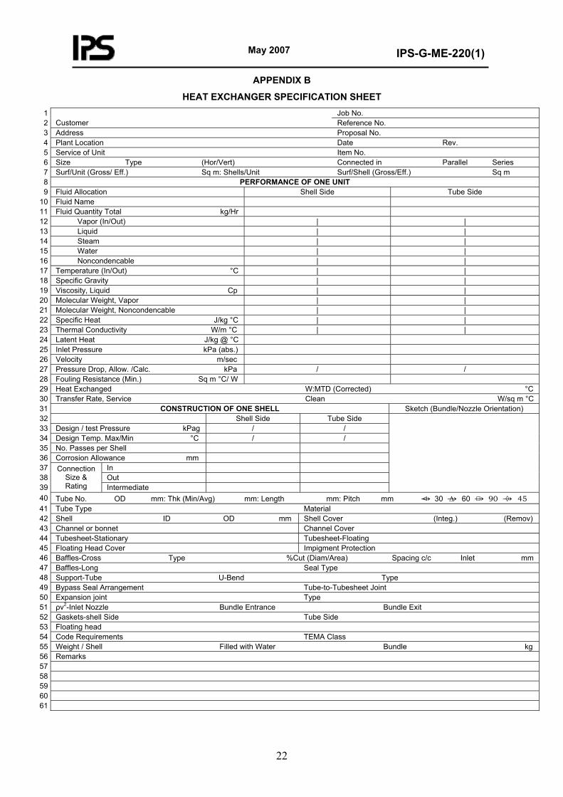
APPENDIX B
HEAT EXCHANGER SPECIFICATION SHEET Job No. 1 Reference No. Customer 2 Proposal No. Address 3
Rev. Date Plant Location 4 Item No. Service of Unit 5
Series Parallel Connected in (Hor/Vert) Type Size 6 Sq m Surf/Shell (Gross/Eff.) Sq m: Shells/Unit Surf/Unit (Gross/ Eff.) 7
PERFORMANCE OF ONE UNIT 8 Tube Side Shell Side Fluid Allocation 9
Fluid Name 10 Fluid Quantity Total kg/Hr 11 | | Vapor (In/Out) 12 | | Liquid 13 | | Steam 14 | | Water 15 | | Noncondencable 16 | | Temperature (In/Out) °C 17 | | Specific Gravity 18 | | Viscosity, Liquid Cp 19 | | Molecular Weight, Vapor 20 | | Molecular Weight, Noncondencable 21 | | Specific Heat J/kg °C 22 | | Thermal Conductivity W/m °C 23 Latent Heat J/kg @ °C 24 Inlet Pressure kPa (abs.) 25 Velocity m/sec 26 / / Pressure Drop, Allow. /Calc. kPa 27 Fouling Resistance (Min.) Sq m °C/ W 28
W:MTD (Corrected) °C Heat Exchanged 29 Clean W/sq m °C Transfer Rate, Service 30
Sketch (Bundle/Nozzle Orientation) CONSTRUCTION OF ONE SHELL 31 Tube Side Shell Side 32
/ / Design / test Pressure kPag 33 / / Design Temp. Max/Min °C 34 No. Passes per Shell 35 Corrosion Allowance mm 36 In 37 Out 38
Intermediate
Connection Size & Rating 39
Tube No. OD mm: Thk (Min/Avg) mm: Length mm: Pitch mm → 30 →Δ 60 → 90 →◊ 45 40 Material Tube Type 41 Shell Cover (Integ.) (Remov) Shell ID OD mm 42 Channel Cover Channel or bonnet 43 Tubesheet-Floating Tubesheet-Stationary 44 Impigment Protection Floating Head Cover 45
Baffles-Cross Type %Cut (Diam/Area) Spacing c/c Inlet mm 46 Seal Type Baffles-Long 47
Type U-Bend Support-Tube 48 Tube-to-Tubesheet Joint Bypass Seal Arrangement 49 Type Expansion joint 50
Bundle Exit Bundle Entrance ρv2-Inlet Nozzle 51 Tube Side Gaskets-shell Side 52
Floating head 53 TEMA Class Code Requirements 54
Bundle kg Filled with Water Weight / Shell 55 Remarks 56 57 58 59 60 61

May 2007
IPS-G-ME-220(1)
23
APPENDIX C
SCOPE OF INSPECTION AND TESTING
Unless otherwise specified scope of inspection for shell and tube heat exchanger shall be as follows:
C.1 Material Inspection
a) Review of material certificates;
b) Identification of material.
C.2 Welding procedure related PQR and welder's/welding operator's performance qualification test.
a) Review of welding procedure specification (WPS);
b) Review of welding procedure qualification Records (PQR);
c) Review of welders’/welding operators’ performance qualification records.
C.3 Random witness in fabrication process, such as edge preparation, fit-up, back-chipping and finish-weld tube-hole preparation and finish, tube expansion, seal welding etc.
C.4 Review of records of post weld heat treatment (if any).
C.5 Non-destructive Examination (where applicable).
a) Monitoring of radiographic examination and review of radiographs
b) Witness of ultrasonic examination
c) Witness of magnetic particle examination.
C.6 Check of hardness test on welds if specified.
C.7 Pressure Tests
a) Witness of hydrostatic test
b) Witness of pneumatic test.
C.8 Final Inspection
a) Visual inspection;
b) Check of dimensions.
C.9 Painting inspection if applicable.
C.10 Review and endorsement of inspection reports issued by manufacturers.

May 2007
IPS-G-ME-220(1)
24
APPENDIX D
MANUFACTURER’S DIMENSIONAL RECORDS
(to be continued)
May 2007
IPS-G-ME-220(1)
25
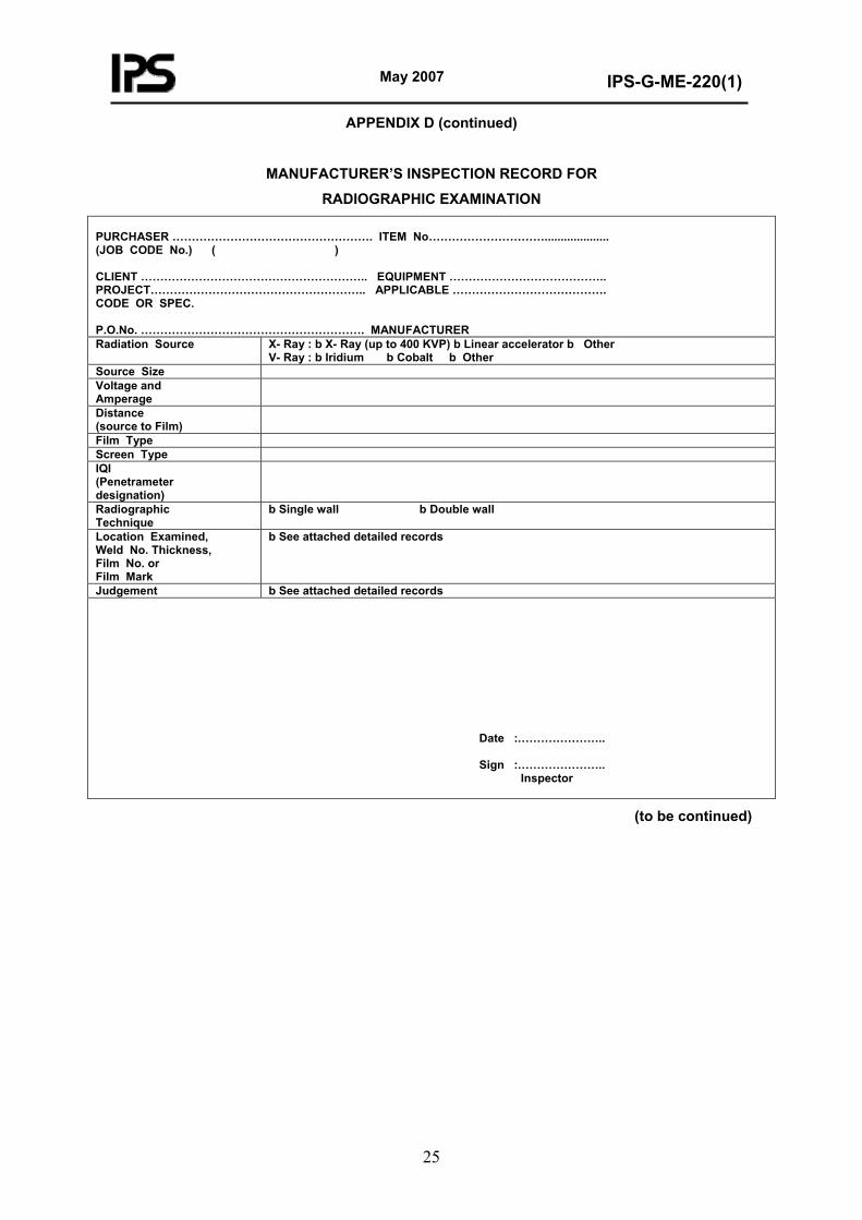
APPENDIX D (continued)
MANUFACTURER’S INSPECTION RECORD FOR
RADIOGRAPHIC EXAMINATION PURCHASER ……………………………………………. ITEM No………………………….................... (JOB CODE No.) ( ) CLIENT ………………………………………………….. EQUIPMENT ………………………………….. PROJECT……………………………………………….. APPLICABLE …………………………………. CODE OR SPEC. P.O.No. …………………………………………………. MANUFACTURER Radiation Source X- Ray : b X- Ray (up to 400 KVP) b Linear accelerator b Other
V- Ray : b Iridium b Cobalt b Other Source Size Voltage and Amperage
Distance (source to Film)
Film Type Screen Type IQI (Penetrameter designation)
Radiographic Technique
b Single wall b Double wall
Location Examined, Weld No. Thickness, Film No. or Film Mark
b See attached detailed records
Judgement b See attached detailed records Date :………………….. Sign :………………….. Inspector
(to be continued)

May 2007
IPS-G-ME-220(1)
26
APPENDIX D (continued)
MANUFACTURER’S INSPECTION RECORD
FOR ULTRASONIC EXAMINATION
PURCHASER………………………………………ITEM No………………………………………………… (JOB CODE No.) ( ) CLIENT…………………………………………….. EQUIPMENT …………………………………………… PROJECT …………………………………………. APPLICABLE CODE OR SPEC. ………………………………………. P.O.No. …………………………………………….MANUFACTURER ………………………………………
TYPE OF EQUIPMENT
Brand name: Type:
Method
Transducer type
Transducer frequency (MHz)
Transducer size
Transducer material
Reflection angle
Remarks
Angle Beam Straight Beam Reference Sensitivity
Basic calibration block (size)
Calibration block for pipe (size)
Reference hole and sensitivity
Angle Beam Method
Straight Beam Method
Angle Beam Method
Scanning Sensitivity Straight Beam
Method
Coupling Medium
b Oil b Glycerin b Water b Other
Surface Condition
b As ground b Other Angle Beam Method
b From outside b From inside b Perpendicular to weld b Parallel to weld
Scanning Direction
Straight Beam Method
b From outside b From inside
Location Examined
b See attached detailed records
Judgement b See attached detailed records
Date:----------------------------------Sign:--------------------------------- Inspector
(to be continued)
May 2007
IPS-G-ME-220(1)
27
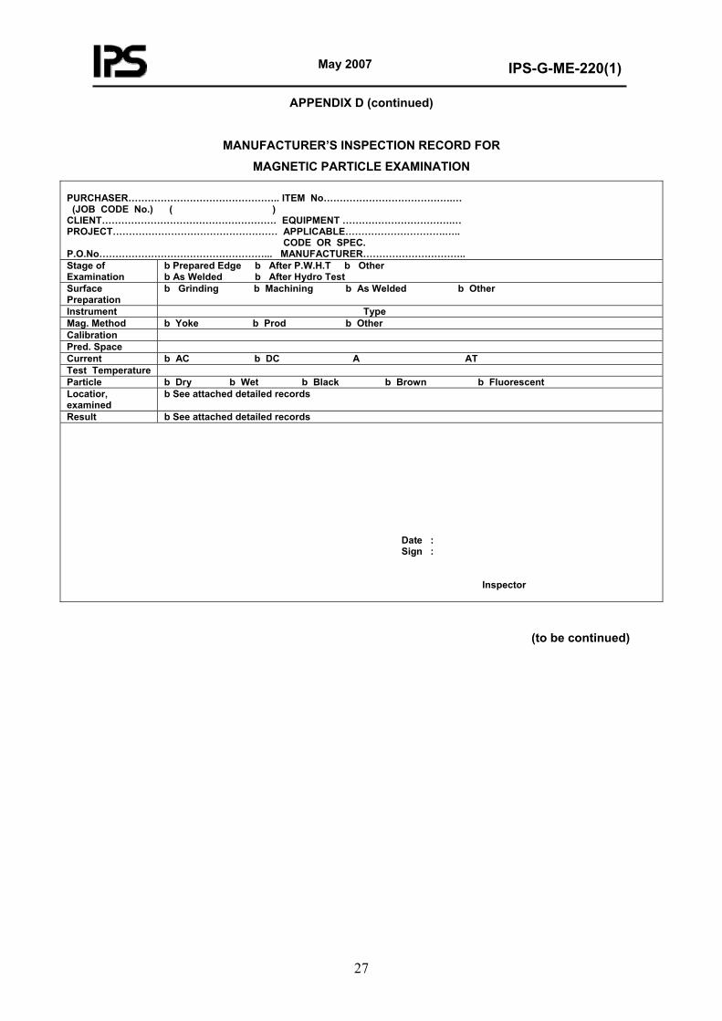
APPENDIX D (continued)
MANUFACTURER’S INSPECTION RECORD FOR
MAGNETIC PARTICLE EXAMINATION PURCHASER……………………………………….. ITEM No………………………………….… (JOB CODE No.) ( ) CLIENT……………………………………………… EQUIPMENT …………………………….… PROJECT…………………………………………… APPLICABLE………………………….….. CODE OR SPEC. P.O.No……………………………………………... MANUFACTURER………………………….. Stage of Examination
b Prepared Edge b After P.W.H.T b Other b As Welded b After Hydro Test
Surface Preparation
b Grinding b Machining b As Welded b Other
Instrument Type Mag. Method b Yoke b Prod b Other Calibration Pred. Space Current b AC b DC A AT Test Temperature Particle b Dry b Wet b Black b Brown b Fluorescent Locatior, examined
b See attached detailed records
Result b See attached detailed records Date : Sign : Inspector
(to be continued)
May 2007
IPS-G-ME-220(1)
28
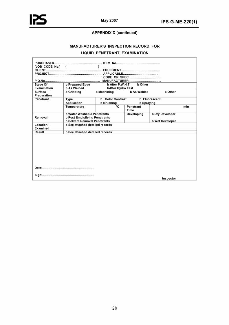
APPENDIX D (continued)
MANUFACTURER'S INSPECTION RECORD FOR
LIQUID PENETRANT EXAMINATION PURCHASER……………………………………….. ITEM No………………………………….… (JOB CODE No.) ( ) CLIENT……………………………………………… EQUIPMENT …………………………….… PROJECT…………………………………………… APPLICABLE………………………….….. CODE OR SPEC…………………………. P.O.No……………………………………………... MANUFACTURER………………………….. Stage Of Examination
b Prepared Edge b After P.W.H.T b Other b As Welded bAfter Hydro Test
Surface Preparation
b Grinding b Machining b As Welded b Other
Type b Color Contrast b Fluorescent Application b Brushing b Spraying
Penetrant
Temperature °C Penetrant Time
min
Removal
b Water Washable Penetrants b Post Emulsifying Penetrants b Solvent Removal Penetrants
Developing b Dry Developer b Wet Developer
Location Examined
b See attached detailed records
Result b See attached detailed records Date:-------------------------------------------------- Sign:-------------------------------------------------- Inspector