Engineering a Safer and More Secure Worldpsas.scripts.mit.edu/home/wp-content/uploads/2015/... ·...
70
Engineering a Safer and More Secure World Nancy Leveson MIT
Transcript of Engineering a Safer and More Secure Worldpsas.scripts.mit.edu/home/wp-content/uploads/2015/... ·...

Engineering a Safer and
More Secure World
Nancy LevesonMIT


Topics
• What is the problem? Why do we need something new?
• Applying systems theory to system safety engineering
• STAMP: a new model of accident causality
• Tools
• Does it work? (Evaluations)
• Conclusions

Our current tools are all 40-65 years old
but our technology is very different today
1940 20101980 202019901950 1960 1970 2000
FMEA FTA
HAZOP
Bow Tie
(CCA)
FTA + ETA
ETA Introduction of computer control
Exponential increases in complexity
Lots of new technology

Software has Revolutionized Engineering (1)
1. Software does not “fail”
+ =General
Purpose
Machine
SoftwareSpecial
Purpose
Machine
Software is simply the design of a machine abstracted
from its physical realization
• Advantages
– Machines that were physically impossible or impractical to build become feasible
– Design can be changed without retooling or manufacturing
– Can concentrate on steps to be achieved without worrying about how steps will be realized physically

Software has Revolutionized Engineering (2)
2. The role of software in accidents almost always involves flawed requirements
– Incomplete or wrong assumptions about operation of controlled system or required operation of computer
– Unhandled controlled-system states and environmental conditions
• Merely trying to get the software “correct” or to make it reliable
will not make it safer under these conditions
Autopilot
Expert Requirements Software
Engineer
Design
of
Autopilot

Software has Revolutionized Engineering (3)
3. Software allows almost unlimited system complexity
Can no longer
– Plan, understand, anticipate, and guard against all undesired
system behavior
– Exhaustively test to get out all design errors
Now have two types of accidents:
Component Failure Accidents
• Single or multiple component failures
• Usually assume random failure
Component Interaction Accidents
• Arise in interactions among components
• Related to interactive and dynamic complexity

It’s only a random
failure, sir! It will
never happen again.

Accident with No Component Failures
• Mars Polar Lander
– Have to slow down spacecraft to land safely
– Use Martian atmosphere, parachute, descent engines (controlled by software)
– Software knows landed because of sensitive sensors on landing legs. Cut off engines when determine have landed.
– But “noise” (false signals) by sensors generated when parachute opens. Not in software requirements.
– Software not supposed to be operating at that time but software engineers decided to start early to even out load on processor
– Software thought spacecraft had landed and shut down descent engines

Another Example
• Navy aircraft were ferrying missiles from one location to
another.
• One pilot executed a planned test by aiming at aircraft in
front and firing a dummy missile.
• Nobody involved knew that the software was designed to
substitute a different missile if the one that was
commanded to be fired was not in a good position.
• In this case, there was an antenna between the dummy
missile and the target so the software decided to fire a
live missile located in a different (better) position instead.

A BC
Unreliable but not unsafeUnsafe but not unreliable
Unreliable and unsafe
Confusing Safety and Reliability
Preventing Component or Functional
Failures is NOT Enough
Scenarios
involving failures
Unsafe
scenarios

Software has Revolutionized Engineering (4)
4. Software changes the role of humans in systems
Typical assumption is that operator error is cause of most
incidents and accidents
– So do something about operator involved (admonish, fire,
retrain them)
– Or do something about operators in general
• Marginalize them by putting in more automation
• Rigidify their work by creating more rules and procedures

A Systems View of Operator Error
• Operator error is a symptom, not a cause
• All behavior affected by context (system) in which occurs
– Role of operators is changing in software-intensive systems as is the errors they make
– Designing systems in which operator error inevitable and then blame accidents on operators rather than designers
• To do something about operator error, must look at system in which people work:
– Design of equipment
– Usefulness of procedures
– Existence of goal conflicts and production pressures
• Human error is a symptom of a system that needs to be redesigned

Human factors
concentrates on the
“screen out”
Engineering
concentrates on the
“screen in”

Not enough attention on integrated
system as a whole

We Need Something New
• New levels of complexity, software, human factors do not
fit into a reductionist, reliability-oriented world.
• Trying to shoehorn new technology and new levels of
complexity into old methods will not work

System Theory as the
Foundation for System Safety

The Problem is Complexity
Ways to Cope with Complexity
• Analytic Reduction
• Statistics
• Systems Theory and Systems Engineering

Analytic Reduction
• Divide system into distinct parts for analysis
Physical aspects Separate physical components or functions
Behavior Events over time
• Examine parts separately and later combine analysis results
• Assumes such separation does not distort phenomenon
– Each component or subsystem operates independently
– Analysis results not distorted when consider components separately
– Components act the same when examined singly as when playing their part in the whole
– Events not subject to feedback loops and non-linear interactions
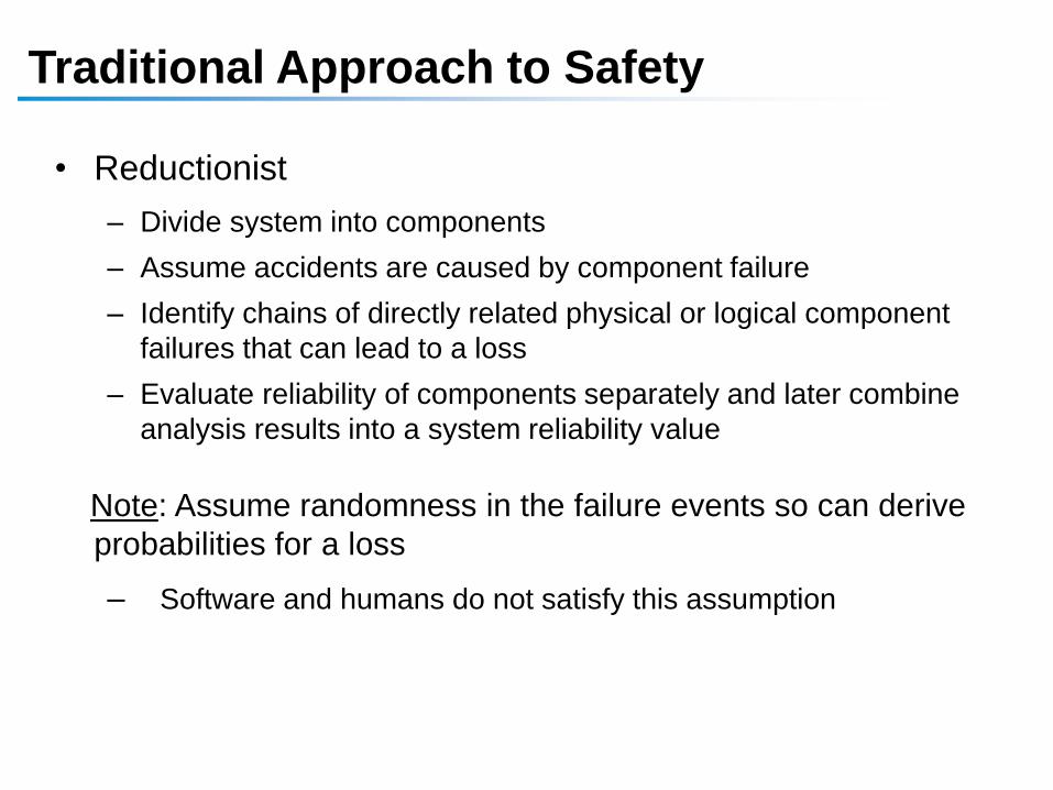
Traditional Approach to Safety
• Reductionist
– Divide system into components
– Assume accidents are caused by component failure
– Identify chains of directly related physical or logical component
failures that can lead to a loss
– Evaluate reliability of components separately and later combine
analysis results into a system reliability value
Note: Assume randomness in the failure events so can derive
probabilities for a loss
– Software and humans do not satisfy this assumption

Accident Causality Models
• Underlie all our efforts to engineer for safety
• Explain why accidents occur
• Determine the way we prevent and investigate accidents
• May not be aware you are using one, but you are
• Imposes patterns on accidents
“All models are wrong, some models are useful”
George Box

Heinrich’s Domino Model of Accident
Causation (1932)

Domino “Chain of events” Model
Chain of Failure Events
Cargo
door fails
Causes Floor
collapses
Causes Hydraulics
fail
Causes Airplane
crashes
DC-10:

Variants of Domino Model
• Bird and Loftus (1976)
– Lack of control by management, permitting
– Basic causes (personal and job factors) that lead to
– Immediate causes (substandard practices/conditions/errors), which are
the proximate cause of
– An accident or incident, which results in
– A loss.
• Adams (1976)
– Management structure (objectives, organization, and operations)
– Operational errors (management or supervisor behavior)
– Tactical errors (caused by employee behavior and work conditions)
– Accident or incident
– Injury or damage to persons or property.

Reason Swiss Cheese (1990)

• Forms the basis for most safety engineering and reliability
engineering analysis:
FTA, PRA, FMEA/FMECA, Event Trees, etc.
and design (concentrate on dealing with component failure):
Redundancy and barriers (to prevent failure propagation),
High component integrity and overdesign,
Fail-safe design,
Operational procedures, ….
Accidents as Chains of Failure Events

Chain-of-events example

Standard Approach does not Handle
• Component interaction accidents
• Systemic factors (affecting all components and barriers)
• Software and software requirements errors
• Human behavior (in a non-superficial way)
• System design errors
• Indirect or non-linear interactions and complexity
• Migration of systems toward greater risk over time (e.g., in search for greater efficiency and productivity)

Analytic Reduction does not Handle
• Component interaction accidents
• Systemic factors (affecting all components and barriers)
• Software and software requirements errors
• Human behavior (in a non-superficial way)
• System design errors
• Indirect or non-linear interactions and complexity
• Migration of systems toward greater risk over time (e.g., in search for greater efficiency and productivity)

• “But the world is too complex to look at the whole, we
need to look at individual components and then combine
the results”
• Right?

Systems Theory
• Developed for systems that are
– Too complex for complete analysis
• Separation into (interacting) subsystems distorts the results
• The most important properties are emergent
– Too organized for statistics
• Too much underlying structure that distorts the statistics
• New technology and designs have no historical information
• First used on ICBM systems of 1950s/1960s
• Basis for system engineering and system safety

Systems Theory (2)
• Focuses on systems taken as a whole, not on parts
taken separately
• Emergent properties
– Some properties can only be treated adequately in their
entirety, taking into account all social and technical aspects
“The whole is greater than the sum of the parts”
– These properties arise from relationships among the parts of
the system
How they interact and fit together

Emergent properties(arise from complex interactions)
Process
Process components interact in
direct and indirect ways
Safety and security are emergent properties

Controller
Controlling emergent properties
(e.g., enforcing safety constraints)
Process
Control Actions Feedback
Individual component behavior
Component interactions
Process components interact in
direct and indirect ways

Controller
Controlling emergent properties
(e.g., enforcing safety constraints)
Process
Control Actions Feedback
Individual component behavior
Component interactions
Process components interact in
direct and indirect ways
Air Traffic Control:
Safety
Throughput

Controls/Controllers Enforce Safety Constraints
• Power must never be on when access door open
• Two aircraft must not violate minimum separation
• Aircraft must maintain sufficient lift to remain airborne
• Public health system must prevent exposure of public to
contaminated water and food products
• Pressure in a offshore well must be controlled
• Runway incursions and operations on wrong runways or
taxiways must be prevented

Controls/Controllers Enforce Safety Constraints
• Bomb must not detonate without positive action by
authorized person
• Submarine must always be able to blow the ballast tanks
and return to surface
• Truck drivers must not drive when sleep deprived
• Integrity of hull must be maintained on a submarine
• Fire must not be initiated on a friendly target

A Broad View of “Control”
Component failures and unsafe interactions may be “controlled” through design
(e.g., redundancy, interlocks, fail-safe design)
or through process
– Manufacturing processes and procedures
– Maintenance processes
– Operations
or through social controls
– Governmental or regulatory
– Culture
– Insurance
– Law and the courts
– Individual self-interest (incentive structure)

There may be multiple controllers, processes,
and levels of control
(with various types of communication between them)
Each controller enforces
specific constraints, which
together enforce the system
level constraints (emergent
properties)
Controller
Controller Controller
Controller
Controller
Physical Process 1 Physical Process 2

Example
Safety
Control
Structure

8/2/2006 41
Status
Track Data
Fire Control
Radar
Operators
Engage Target
Operational Mode Change
Readiness State Change
Weapons Free / Weapons Hold
Operational Mode
Readiness State
System Status
Track Data
Weapon and System Status
Command
Authority
Doctrine
Engagement Criteria
Training
TTP
Workarounds
Early Warning
System
Status Request
Launch Report
Status Report
Heartbeat
Radar Tasking
Readiness Mode Change
Status Request
Acknowledgements
BIT Results
Health & Status
Abort
Arm
BIT Command
Task Load
Launch
Operating Mode
Power
Safe
Software Updates
Flight
Computer
Interceptor
SimulatorLaunch Station
Fire DIsable
Fire Enable
Operational Mode Change
Readiness State Change
Interceptor Tasking
Task Cancellation
Command Responses
System Status
Launch Report
Launcher
Launch Position
Stow Position
Perform BIT
Interceptor
H/W
Arm
Safe
Ignite
BIT Info
Safe & Arm Status
BIT Results
Launcher Position
Abort
Arm
BIT Command
Task Load
Launch
Operating Mode
Power
Safe
Software Updates
Acknowledgements
BIT Results
Health & Status
Breakwires
Safe & Arm Status
Voltages
Exercise Results
Readiness
Status
Wargame Results
Safety
Control
Structure for
FMIS

Safety Constraints
• Each component in the control structure has
– Assigned responsibilities, authority, accountability
– Controls that can be used to enforce safety
constraints
• Each component’s behavior is influenced by
– Context (environment) in which operating
– Knowledge about current state of process

Controlled Process
Process
Model
Control
Actions Feedback
Role of Process Models in Control
• Controllers use a process model to determine control actions
• Accidents often occur when the process model is incorrect
– How could this happen?
• Four types of unsafe control actions:• Control commands required for safety
are not given
• Unsafe ones are given
• Potentially safe commands given too early, too late
• Control stops too soon or applied too long
Controller
43(Leveson, 2003); (Leveson, 2011)
Control
Algorithm

Identifying Causal Scenarios
44
Inadequate Control
Algorithm
(Flaws in creation,
process changes,
incorrect modification
or adaptation)
Controller
Process Model
(inconsistent,
incomplete, or
incorrect)
Control input or external
information wrong or
missing
Actuator
Inadequate
operation
Inappropriate,
ineffective, or
missing control
action
Sensor
Inadequate
operation
Inadequate or
missing feedback
Feedback Delays
Component failures
Changes over time
Controlled Process
Unidentified or out-
of-range
disturbance
Controller
Process input missing or wrongProcess output
contributes to
system hazard
Incorrect or no information
provided
Measurement inaccuracies
Feedback delays
Delayedoperation
Conflicting control actions
Missing or wrong
communication with
another controller
Controller

STAMP (System-Theoretic Accident
Model and Processes)
• Defines safety as a control problem (vs. failure problem)
• Applies to very complex systems
• Includes software, humans, new technology
• Based on systems theory and systems engineering
• Expands the traditional model of the accident causation
(cause of losses)
– Not just a chain of directly related failure events
– Losses are complex processes

Safety as a Dynamic Control Problem (STAMP)
• Events result from lack of enforcement of safety constraints in system design and operations
• Goal is to control the behavior of the components and systems as a whole to ensure safety constraints are enforced in the operating system
• A change in emphasis:
“prevent failures”
“enforce safety/security constraints on system behavior”

Changes to Analysis Goals
• Hazard analysis:
– Ways that safety constraints might not be enforced so can
be eliminated or mitigated in the design or operations
(vs. chains of failure events leading to accident and their
probabilities)
• Accident Analysis (investigation)
– Why safety control structure was not adequate to prevent
loss
(vs. what failures led to loss and who responsible)

STAMP: Theoretical Causality Model
Accident/Event Analysis
CAST
Hazard Analysis
STPA
System Engineering
(e.g., Specification,
Safety-Guided Design,
Design Principles)
Early Concept Analysis
STECA
Risk Management
Operations
Management Principles/
Organizational Design
Identifying Leading
Indicators
Organizational/Cultural
Risk Analysis
Tools
Processes
Regulation
Security Analysis
STPA-Sec


STPASTECA

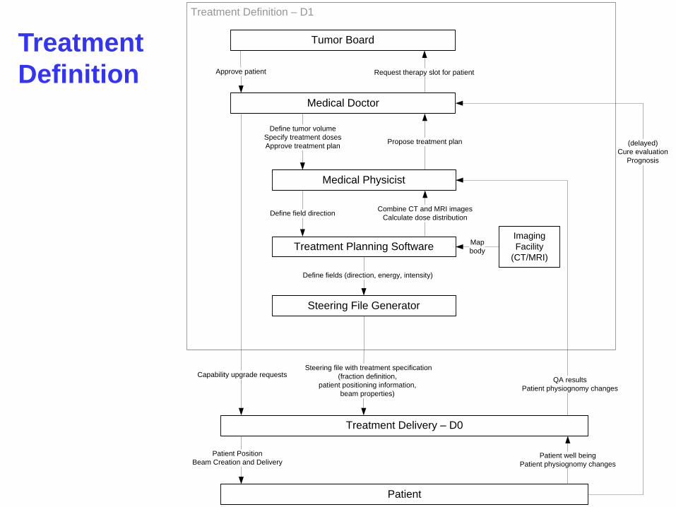
STPA Example:
PSI Gantry 2 Proton Radiation Therapy

High-Level Safety
Control Structure
for Gantry 2
Treatment Delivery
Patient
Treatment Definition
Therapeutic Requirements
1. Treatment Specifications
(fraction definition,
target positioning information,
steering file)
2. Capability Upgrade Requests
Patient Preparation
Beam Creation and Delivery
QA results
Patient physionomy
change
Patient well-being
Patient physiognomy changes
(delayed)
Patient health outcome
Treatment Delivery – D0
Patient
Treatment Definition – D1
Steering file with treatment specification
(fraction definition,
patient positioning information,
beam properties)
Patient Position
Beam Creation and Delivery
QA results
Patient physiognomy changes
(delayed)
Cure evaluation
Prognosis
Medical Doctor
Medical Physicist
Treatment Planning Software
Steering File Generator
Imaging
Facility
(CT/MRI)
Propose treatment plan
Define tumor volume
Specify treatment doses
Approve treatment plan
Map
body
Combine CT and MRI images
Calculate dose distributionDefine field direction
Define fields (direction, energy, intensity)
Patient well being
Patient physiognomy changes
Capability upgrade requests
Tumor Board
Request therapy slot for patientApprove patient
Treatment
Definition

PROSCAN
Design TeamOperations Management
Treatment Delivery – D1
Patient
Treatment Definition – D0
Patient Position
Beam Creation and Delivery
QA results
Maintenance Operators Medical Team
PROSCAN facility (physical actuators and sensors, automated controllers)
Software revisions
Hardware modifications
Problem reports
Incidents
Change requests
Performance audits
Work orders
ResourcesProcedures Problem reports
Change requests
Problem reports
Change requests
Hardware
replacements
Revised
operating procedures
Start treatment
Interrupt treatment
Procedures Problem reports
Change requests
Test
results
QA results
Sensor infoPatient position
Interrupt treatment
Room
clear
(delayed)
Cure evaluation
Prognosis
Patient well being
Patient physiognomy
changes
Panic button
Treatment specifications
(fraction definition, patient positioning information, beam characteristics)
Capability upgrade requests
Position
Movement
Patient
position
Zooming into Treatment Delivery

STPA Hazard Analysis
Starting with system-level hazards (e.g., overdose of
radiation or radiation to wrong place on body)
– Identify system safety requirements:
e.g., radiation must never be delivered if patient is not in
correct position on the table
– Flow down safety requirements for each system
component
e.g., operator must not deliver treatment if patient is not on
the table and in the correct position
Next step is to identify scenarios leading to unsafe
control actions and eliminate or mitigate them

Causal Scenarios
• Scenario 1 - Operator was expecting patient to have been
positioned, but table positioning was delayed compared to plan
because of
– Delays in patient preparation
– Delays in patient transfer to treatment area;
– Unexpected delays in beam availability
– Technical issues being processed by other personnel without proper
communication with the operator.
• Controls:
– Provide operator with direct visual feedback to the gantry coupling point,
and require check that patient has been positioned before starting
treatment (M1).
– Provide a physical interlock that prevents beam-on unless table
positioned according to plan

Example Causal Scenarios (2)
• Scenario 2 - Operator is asked to turn the beam on outside of a
treatment sequence (e.g. because the design team wants to
troubleshoot a problem) but inadvertently starts treatment and does
not realize that the facility proceeds with reading the treatment plan.
• Controls:
– Reduce the likelihood that non-treatment activities have access to
treatment related input by creating a non-treatment mode to be used for
QA and experiments, during which facility does not read treatment plans
that may have been previously been loaded (M2);
– Make procedures (including button design if pushing a button is what
starts treatment) to start treatment sufficiently different from non-
treatment beam on procedures that the confusion is unlikely.

System Theoretic Early Concept Analysis:STECA (Dr. Cody Fleming)
ConOps
Model Generation
Model-Based Analysis
Missing, inconsistent,
incomplete information
Vulnerabilities, risks, tradeoffs
System, software, human
requirements
(including information rqtms.)
Architectural and design analysis
to eliminate and control hazards
Unspecified Assumptions

Applies to Security Too (AF Col. Bill Young)
• Currently primarily focus on tactics
– Cyber security often framed as battle between adversaries
and defenders (tactics)
– Requires correctly identifying attackers motives,
capabilities, targets
• Can reframe problem in terms of strategy
– Identify and control system vulnerabilities (vs. reacting to
potential threats)
– Top-down strategy vs. bottom-up tactics approach
– Tactics tackled later

Integrated Approach to Safety and Security:
• Safety: prevent losses due to unintentional actions by
benevolent actors
• Security: prevent losses due to intentional actions by
malevolent actors
• Key difference is intent
• Common goal: loss prevention
– Ensure that critical functions and services provided by networks
and services are maintained
– New paradigm for safety will work for security too
• May have to add new causes, but rest of process is the same
– A top-down, system engineering approach to designing safety
and security into systems

Low
High
Concept Requirements Design Build Operate
Co
st
of
Fix
Attack/Accident
Response
System
Safety/Security
Requirements
Systems
Engineering
Cyber
Security/Safety
“Bolt-on”
Safety/Secure
Systems
Thinking
Build safety and security into
system from beginning

Evaluation: Does it Work?

Is it Practical?
• STPA has been or is being used in a large variety of industries
– Spacecraft
– Aircraft
– Air Traffic Control
– UAVs (RPAs)
– Defense
– Automobiles (GM, Ford, Nissan)
– Medical Devices and Hospital Safety
– Chemical plants
– Oil and Gas
– Nuclear and Electrical Power
– C02 Capture, Transport, and Storage
– Finance
– Etc.

Does it Work?
• Most of these systems are very complex (e.g., the new
U.S. missile defense system)
• In all cases where a comparison was made (to FTA,
HAZOP, FMEA, ETA, etc.)
– STPA found the same hazard causes as the old methods
– Plus it found more causes than traditional methods
– In some evaluations, found accidents that had occurred that
other methods missed (e.g., EPRI)
– Cost was orders of magnitude less than the traditional
hazard analysis methods
– Same results for security evaluations by CYBERCOM

8/2/2006 65
Status
Track Data
Fire Control
Radar
Operators
Engage Target
Operational Mode Change
Readiness State Change
Weapons Free / Weapons Hold
Operational Mode
Readiness State
System Status
Track Data
Weapon and System Status
Command
Authority
Doctrine
Engagement Criteria
Training
TTP
Workarounds
Early Warning
System
Status Request
Launch Report
Status Report
Heartbeat
Radar Tasking
Readiness Mode Change
Status Request
Acknowledgements
BIT Results
Health & Status
Abort
Arm
BIT Command
Task Load
Launch
Operating Mode
Power
Safe
Software Updates
Flight
Computer
Interceptor
SimulatorLaunch Station
Fire DIsable
Fire Enable
Operational Mode Change
Readiness State Change
Interceptor Tasking
Task Cancellation
Command Responses
System Status
Launch Report
Launcher
Launch Position
Stow Position
Perform BIT
Interceptor
H/W
Arm
Safe
Ignite
BIT Info
Safe & Arm Status
BIT Results
Launcher Position
Abort
Arm
BIT Command
Task Load
Launch
Operating Mode
Power
Safe
Software Updates
Acknowledgements
BIT Results
Health & Status
Breakwires
Safe & Arm Status
Voltages
Exercise Results
Readiness
Status
Wargame Results
Safety
Control
Structure for
FMIS

Summary
• More comprehensive and powerful approach to safety (and
security)
– Examines inter-relationships rather than just linear cause-effect
chains.
– Includes what consider now (component failures) but more (e.g.,
system design errors, requirements flaws)
• Includes social, human, software-related factors
• Top-down system engineering approach
– Safety-guided design starts early at concept formation
– Generates safety/security requirements from hazard analysis
• Handles much more complex systems than traditional safety
analysis approaches and costs less

Paradigm Change
• Does not imply what previously done is wrong and new
approach correct
• Einstein:
“Progress in science (moving from one
paradigm to another) is like climbing a
mountain”
As move further up, can
see farther than on lower points

Paradigm Change (2)
New perspective does not invalidate
the old one, but extends and enriches
our appreciation of the valleys below
Value of new paradigm often depends on
ability to accommodate successes and
empirical observations made in old paradigm.
New paradigms offer a broader,
rich perspective for interpreting
previous answers.

Systems Thinking

A life without adventure is likely to be unsatisfying, but a life
in which adventure is allowed to take whatever form it will,
is likely to be short.
Bertrand Russell