Engineering 5. Engineering Design D - bücher.de
52
1 Engineering D 5. Engineering Design The development and design of engineering sys- tems following a methodical approach based on information from the literature [5.1–3] is a useful procedure. The guidelines for design methodology have also been applied to interdisciplinary de- velopment projects of this type, using aids such as requirements lists, the functional structure and morphological boxes, to name just a few. During the design phase of the product develop- ment process it is important to comply with the basic design rules: simple, clear and safe [5.3]. Several examples that clearly show the realiza- tion of these three criteria are included in this chapter. 5.1 Basics .................................................. 1 5.2 Precisely Defining the Task .................... 2 5.2.1 Task............................................ 2 5.2.2 Functional Description .................. 2 5.2.3 Requirements List ........................ 4 5.3 Conceptual Design ................................ 5 5.4 Design ................................................. 8 5.4.1 Identify Requirements that Determine the Design and Clarify the Spatial Conditions ... 8 5.4.2 Structuring and Rough Design of the Main Functional Elements Determining the Design and Selection of Suitable Designs ... 9 5.4.3 Detailed Design of the Main and Secondary Functional Elements 10 5.4.4 Evaluation According to the Technical and Economic Criteria, and Specification of the Preliminary Overall Design ... 11 5.4.5 Subsequent Consideration, Error Analysis, and Improvement ........... 12 5.5 Design and Manufacturing for the Environment ............................. 13 5.5.1 Life Cycle Format for Product Evaluation .................. 14 5.5.2 Life Cycle Stages for a Product ........ 16 5.5.3 Product Examples: Automobiles and Computers .......... 18 5.5.4 Design for the Environment (DFE) ... 25 5.5.5 System-Level Observations ............ 26 5.6 Failure Mode and Effect Analysis for Capital Goods .................................. 27 5.6.1 General Innovations for the Application of FMEA ........... 27 5.6.2 General Rules to Carry Out FMEA ..... 27 5.6.3 Procedure ................................... 29 5.6.4 Further Use of FMEA Results ........... 34 References .................................................. 34 5.1 Basics The methodical approach to the development and design of technical systems (engineering design) has estab- lished itself in virtually all design departments. Teaching specialized knowledge about methodical design is also a fixed component of the curriculum in the teaching of engineering sciences in universities and technical colleges. Part B 5
Transcript of Engineering 5. Engineering Design D - bücher.de

1
Engineering D5. Engineering Design
The development and design of engineering sys-
tems following a methodical approach based on
information from the literature [5.1–3] is a useful
procedure. The guidelines for design methodology
have also been applied to interdisciplinary de-
velopment projects of this type, using aids such
as requirements lists, the functional structure
and morphological boxes, to name just a few.
During the design phase of the product develop-
ment process it is important to comply with the
basic design rules: simple, clear and safe [5.3].
Several examples that clearly show the realiza-
tion of these three criteria are included in this
chapter.
5.1 Basics .................................................. 1
5.2 Precisely Defining the Task .................... 25.2.1 Task............................................ 25.2.2 Functional Description .................. 25.2.3 Requirements List ........................ 4
5.3 Conceptual Design ................................ 5
5.4 Design ................................................. 85.4.1 Identify Requirements
that Determine the Designand Clarify the Spatial Conditions... 8
5.4.2 Structuring and Rough Designof the Main Functional ElementsDetermining the Designand Selection of Suitable Designs ... 9
5.4.3 Detailed Design of the Mainand Secondary Functional Elements 10
5.4.4 Evaluation According to theTechnical and Economic Criteria,and Specificationof the Preliminary Overall Design ... 11
5.4.5 Subsequent Consideration, ErrorAnalysis, and Improvement ........... 12
5.5 Design and Manufacturingfor the Environment ............................. 135.5.1 Life Cycle Format
for Product Evaluation .................. 145.5.2 Life Cycle Stages for a Product ........ 165.5.3 Product Examples:
Automobiles and Computers .......... 185.5.4 Design for the Environment (DFE) ... 255.5.5 System-Level Observations ............ 26
5.6 Failure Mode and Effect Analysisfor Capital Goods .................................. 275.6.1 General Innovations
for the Application of FMEA ........... 275.6.2 General Rules to Carry Out FMEA ..... 275.6.3 Procedure ................................... 295.6.4 Further Use of FMEA Results ........... 34
References .................................................. 34
5.1 Basics
The methodical approach to the development and designof technical systems (engineering design) has estab-lished itself in virtually all design departments. Teachingspecialized knowledge about methodical design is also
a fixed component of the curriculum in the teachingof engineering sciences in universities and technicalcolleges.
PartB
5

2 Part B Applications in Mechanical Engineering
There are a large number of approaches to designmethodology, which are documented the technical lit-erature. For example, Ehrlenspiel [5.1] focuses moreon the cost approach to product development. Oneway of reducing and identifying costs early, accord-ing to Ehrlenspiel, is integrated product development.In his method on the other hand, Roth [5.2] dividesthe design process into many smaller steps and placesstrong emphasis on the incorporation of design cata-logues in the solution process. Pahl et al. [5.3] workedvery actively on the German guidelines VDI2221 [5.4]and VDI2222 [5.5] and subdivided the design processinto individual activities, to which detailed methodsare assigned. Further methods exist for these pur-poses, for example from Gierse [5.6], Hubka [5.7],Koller [5.8], Bock [5.9] and Rugenstein [5.10]. Theessential aspect of each of these is the structuring ofthe task. This takes place, e.g., by drawing up flowdiagrams and using methodical structuring aids, e.g.,functional structures, efficacy structures or classificationdiagrams [5.11].
The methodical approach to the development ofa technical system is clarified in this chapter using
a practical example from the interdisciplinary fieldof biomedical engineering, based on the methodicalmethod of Pahl et al. [5.3].
According to Pahl et al., the design process is dividedinto four stages:
• precisely defining the task (problem identification)• the concept stage• the design• drawing up the final solution (detailed design)
As the example involves an interdisciplinary devel-opment project, it is particularly important to draw uponly a few, but at the same time all, of the problem orwork-related (sub)functions required for adequate struc-turing of the task and to represent these in a functionalstructure. It is also necessary to use a generally under-stood vocabulary. This enables us to ensure that peoplenot yet involved in the process or people who do nothave engineering training, e.g., medical experts or biol-ogists can easily obtain an overview. This integration ofemployees from the individual specialized fields is nec-essary in order to be able to implement all medical andbiological requirements at a high level.
5.2 Precisely Defining the Task
5.2.1 Task
The engineering system to be developed is a test setupfor experiments with live human cells. The task (prob-lem) for the designers was drawn up by the responsiblemedical experts. An extract from this is shown in thefollowing.
For decades it has been known that certain cells inthe human immune system are practically incapable offunctioning in weightlessness. This can pose a seriousproblem for long-term stays in space on the Interna-tional Space Station (ISS), or flights to Mars. The basicmechanism is to be investigated by means of weightless-ness experiments with the help of parabolic (ballistic)flights. To this end, experimental equipment is to bedesigned with which tests on live cells can be per-formed onboard parabolic flights and in weightlessness.These experiments should also answer the question ofwhether humans are at all capable of living in weight-lessness for any lengthy period. The findings can alsobe used in therapy for diseases of the immune system.It is necessary to mix the living human cells with an
activator liquid and with a stopping liquid after a cer-tain time. All the necessary safety requirements must beobserved.
The designer’s task consists of precisely definingthis problem. This means that they must first draw upa functional engineering description. The aim is to drawup the whole function and all input and output variablesfor the engineering system to be developed.
Cells(Primary T cells)
15 ml, 37 °C
Activator liquid(PMA)
15 ml, 37 °C
Stopping liquid(FA)
60 ml, 4 °C
Cells, activatorand
stopping liquid
1. 2. 3.
Fig. 5.1 Liquids to be mixed
PartB
5.2

Engineering Design 5.2 Precisely Defining the Task 3
5.2.2 Functional Description
The functional engineering description is drawn up bythe responsible designer. It is used to clearly define thetask or problem the designer has been set. At the sametime it provides a basis for discussion with the otherteam members. In this way it is possible to identify earlyon whether there are any communication problems. Ininterdisciplinary projects it is particularly important tointegrate the information of the non-engineering sci-ence team members into the technical preparations andtherefore to create a basis for a methodical approach. Itthis project it was particularly important for the medi-cal experts/biologists and engineers to speak the samelanguage. The functional description is usually verbal.Frequently diagrams or initial sketches are also producedto depict the whole function to be fulfilled transparently.Figure 5.1 shows the outline technology for the test setupto be developed.
This rough structuring was based on notes taken dur-ing team meetings and a functional structure drawn up byone of the medical–biological team members (Fig. 5.2).
This is already very finely structured. However, it isnot drawn up in the usual form used in design methodol-ogy [5.3]. Further, such a precise description of a focused
Closed compartment
JurkatT cells
U937monocytic
cells
PrimaryT cells
A
Electronically controlledautomatic intake
Reaction and samplechambers (changed after
each parabola)
4 °C
B
Electronically controlledautomatic intake
C
Electronically controlledautomatic intake
Rinse Con. ConA PMACD3/CD28
Stopsol.
1%FA
37 °C
V 1A
V 1B
V 1C
V 2A
V 2B
V 2C
V 3A
V 3B
V 3C
V 4A
V 4B
V 4C
V 5A
V 5B
V 5C
V 6A
V 6B
V 6C
V 7A
V 7B
V 7C
Flow
V = ValvesWaste
Fig. 5.2 Functional description from a medical point of view
Hypergravity
20 sec.
WeightlessnesHypergravity
20 sec. 22 sec.
1 min 20 sec
6100 m
7600 m
8500 m
825 km/h
570 km/h
370 km/h
Recoverypoint
Injectionpoint
47° 42°
Fig. 5.3 Flight parabola for generating weightlessness (mi-crogravitation) (after [5.61])
possible solution excludes other approaches and solu-tions in advance. The functional engineering descriptionor the overall function to be fulfilled by the test setupcan be described as follows.
A test setup is to be developed that enables threedifferent cell lines to be mixed, to a large extent ho-
PartB
5.2

4 Part B Applications in Mechanical Engineering
Product: Parabolic FlightO
vera
ll sp
ace
requ
ired
/co
nnec
tion
dim
ensi
ons/
inst
alla
tion
cond
ition
sNo.
Date: 06.02.06 Sheet 03
Requirements SourceRespon-sibilityDescriptive information Numerical info/comments
Aircraft door width – 1.07 m
Aircraft door height – 1.93 m
Cabin length – 20 m
Maximum rack height – 1,500 mm
Fixing points for experimental setup –––
Mean rail spacing (y-axis) a) 503 mm b) 1006 mmHole diameter for screw M10 = 12 mmHole spacing in x direction = n * 25.4 mm > 20 inches (1 inch = 25.4 mm)
Maximum load per unit area over 1 m fixing rail length – 100 kg
Rack structure – Baseplate or frame connected to the seat rail system of the aircraft
– There must not be any parts protruding from the baseplate in the directionof the flooring
Fig. 5.4 Extract from the requirements list
mogeneously, with certain activator liquids at the startof the weightlessness phase. Just before the end of theweightlessness phase a stopping liquid is to be added tothe cell vessels filled with a cell type and an activatorliquid.
In order to fulfil the specified medical requirements,combinations of three different cell liquids, three differ-ent activator liquids and two stopping liquids (Fig. 5.1)must be realized.
The condition of weightlessness was achieved withthe help of parabolic flights. This means that an aircraftflies in a precisely defined parabola and the conditionof weightlessness (micro-gravitation) is available forapproximately 22–25 s (Fig. 5.3).
A main requirement is the fulfilment of all safetyrequirements in the test setup. Primarily, that under nocircumstances may liquids escape from the test setupduring the parabolic flights. Some of the cell lines usedare genetically modified tumor cells and immune cellsisolated from blood donators, and toxic liquids suchas formaldehyde. These could pose a risk to the flightpersonnel during the weightlessness phase. This meansthat all parts that come into contact with the media orcell, activator or stopping liquids must be designed withdouble walls.
A further requirement is that the temperature of thecell and activator liquids must be 37 ◦C and the tem-perature of the stopping liquids must be 4 ◦C (Fig. 5.1).Further points included in an initial functional engineer-ing description are:
• enable fast and easy equipping with liquids• realization of the direct safety stage [5.3], i. e.,leakproof under the conditions in the aircraft• clear functional sequences
• good miscibility of the liquids during the experimentin the cell culture bag• fill under exclusion of air• to a large extent transparent construction for obser-vation of whether air inclusions exist• low weight (mass)• small space requirement• good cost-effectiveness
This initial functional description is the basis for drawingup a requirements list.
5.2.3 Requirements List
When the task or problem is more precisely defined,other individual characteristic values and special re-quirements are determined. It is necessary to adequatelydescribe all of the requirements set, both qualitativelyand quantitatively. In this project this is achieved
• through discussions with the other team members(biologists, medical experts)• through literature and patent research• analysis and evaluation of all applicable rules, reg-ulations, etc. (technical requirements of the aircraftoperator) [5.12]
The results of the precise task definition stage aredocumented in the requirements list. This usuallycontains the objectives to be realized and the pre-vailing conditions in the form of requirements andwishes [5.3]. The requirements must always be ful-filled. The wishes listed are to be realized if possible.The boundary between requirements and wishes canoften not be clearly defined, especially in interdisci-plinary projects. For this reason, such a differentiation
PartB
5.2

Engineering Design 5.3 Conceptual Design 5
Signalend
Saveactivators
Savestopping
liquid
Savecells
Heat37 °C
Energy
Cool4 °C
Energy
Activatorliquid
(3 activators)
Stoppingliquid
(2 liquids)
Cells(3 cell-types)
Transport /doseactivators
Transport /dosestopping
liquid
Transportcells
Signal starttransport
Mixliquids
Transduceenergy
Transduceenergy
Energy
Transduceenergy
Cells,Activators,Stoppingliquid
Saveliquids
Transportof liquids
Transduceenergy
Transduceenergy
Transduceenergy
Cool4 °C
EnergyEnergy Energy
Fig. 5.5 Simplified functional structure
was dispensed with for this project. An extract fromthe requirements list drawn up is shown in Fig. 5.4.At the same time, the requirements list is the le-
gal basis for all further activities, including in thisproject.
5.3 Conceptual Design
In the conceptual design stage the overall function isstructured. The result is a functional structure (Fig. 5.5).This means that the whole system is divided into itssubfunctions and their links.
This procedure enables optimum analysis of thewhole system. Efficacy principles were then assignedto the subfunctions.
Efficacy principles are usually based on physical ef-fects that enable the function to be fulfilled. These arecombined with geometric and material characteristics.In this project, conventional, intuitive and discursivesolution-finding methods [5.3, 13] were used to drawsuitable action principles. In detail:
• conventional (e.g., literature or patent) research• intuitive (e.g., brainstorming)• discursive (e.g., the use of design catalogues).
When suitable efficacy principles have been deter-mined for fulfilling the function, they are assigned to thesubfunctions in a classification diagram. In this projectthe morphological box (Fig. 5.6) was used for this.
The efficacy principles drawn up to fulfil theindividual subfunctions must then be purposefullylinked to each other. When drawing up the con-cept for the test setup it was of primary importancethat the high safety requirements be fulfilled withall the selected efficacy principles. This results indifferent efficacy structures. In practice it is usualto draw up a maximum of three efficacy structures.Figure 5.7 shows the path through the morphologicalbox.
The efficacy structures generated are specified ingreater detail and further developed to form basic solu-tions. The individual basic solutions are then assessed.An extract of the assessment (rating) undertaken in this
PartB
5.3

6 Part B Applications in Mechanical Engineering
OptionF
unct
ion
Heat
Transport/meter
Mix
1. 2. 3. 4.
Cool Peltier cooler Cryogenics Refrigerator principle(compressor +heat exchanger)
Sheet-type heating elements(siliconheatingmats)
Heatcartridges
Infraredradiators
Chemicalreaction(thermalaccumulators)
Flexibletubepump
Pistonpump
Diaphragmpump
Gearpump
Use of thepumps,pressuresurge
Magneticstirrerprinciple
Swivel movementof the vessels(shaker, vibrator)
Source: Novodirect Source: Rübsamen & Herr GmbH
Source: Hewid GmbHSource: Hewid GmbH Source: Hewid GmbH Source: riedborn-apotheke
Source: NovodirectSource: NovodirectSource: NovodirectSource: ismatec
Source: Novodirect
Coolingaccumulators
Fig. 5.6 Morphological box
Source: Novodirect Source: Rübsamen & Herr GmbH
Source: Hewid GmbHSource: Hewid GmbH Source: Hewid GmbH Source: www.riedborn-apotheke.de
Source: NovodirectSource: NovodirectSource: NovodirectSource: ismatec
Source: Novodirect
Option
Fun
ctio
n Coolingaccumulators
Heat
Transport/meter
Mix
1. 2. 3. 4.
Cool Peltier cooler Cryogenics Refrigerator principle(compressor +heat exchanger)
Sheet-type heating elements(siliconheatingmats)
Heatcartridges
Infraredradiators
Chemicalreaction(thermalaccumulators)
Flexibletubepump
Pistonpump
Diaphragmpump
Gearpump
Use of thepumps,pressuresurge
Magneticstirrerprinciple
Swivel movementof the vessels(shaker, vibrator)
Efficacy structure 1 Efficacy structure 2 Efficacy structure 3
Fig. 5.7 Path through the morphological box
project is shown in Fig. 5.8. The assessment criteriaand assessment was carried out by the whole projectteam.
As a result, a basic solution was released tobe drawn up. In general, as in this project, this isthe efficacy structure with the best rating. It forms
PartB
5.3

Engineering Design 5.3 Conceptual Design 7
Assessment criteria
37 °C uniformily distributed in the area of the cell storage and the activator liquids
Weighting(W) W x P
Opt. 3
Item (P)W x P
Opt. 2
Item (P)W x P
Opt. 1
Item (P)
4 °C uniformily distributed in the area of the stopping liquids and in the subsequent storage system
Low energy requirements
Low mass
Sterile pumping system with few mechanical components in area of contact with the pumped media
Total
Percent
0.8 2.430.813.24
1.0 441144
0.6 1.222.441.22
0.7 1.422.132.13
0.5 121224
27.125.330.0
0.750.700.83
Fig. 5.8 Extract from the assessment list
Level 1of the
workingand
storagemodul
Level 3of the
workingand
storagemodul
Connectedcell vessels
Frameconstruction(rack)
Pumpfor theactivators
Temporarily stored cell vessels
Pump for thestopping solutions
Define the basic solution (concept)Release for design
Identify requirements which determine the design Information
Definition
Creation
Des
ign
Rou
gh d
esig
n
Clarify space conditions
Structure into main functional elementsdetermining the design
Rough design of the main functional elementsdetermining the design
Select suitable designs
Rough design other main functional parts
Search for solutions for secondary functions
a)
b) c)Objective Basic rule
Fulfil thefunction
Clear Helps to reliablypredict effects
Economicrealization
Simple Small number ofparts, simple shapes» fast and betterproduction; butsimple also means» clearly arrangefor operation
Safety forman andtheenviron-ment
Safe Consistenttreatmentof issues ofdurability,reliability,lack of accidents
Design
Storage modul4 °C
Pump 2 Pump 1
37°C
37°C
37°C
PMA
Con
AC
D3/
CD
28
Jurk
at T
cel
ls
Prim
ary
T c
ells
Jurk
at T
cel
ls
4°C
Prim
ary
T c
ells
Jurk
at T
cel
ls
Prim
ary
T c
ells
Stop
FA 1%
U93
7 m
ono-
cytic
cel
ls
U93
7 m
ono-
cytic
cel
ls
U93
7 m
ono-
cytic
cel
ls
Fig. 5.9a–c Basic solution, released to be drawn up. (c) Extract from the main design activities (after [5.3])
PartB
5.3

8 Part B Applications in Mechanical Engineering
the basis of the design stage. This is shown inFig. 5.9.
The basic solution consists of two separate mod-ules. The first module is the actual working module,in which the cells, the activator and stopping liquidsand all the necessary units are installed for pumping.This module is divided into three levels/submodulespositioned on top of each other. Level 1 contains thepump for the stopping liquids and the cell vesselsstored for filling, which is separated from the pumpby a wall. Above this is the level for the power sup-ply and controls. The top area contains the pump forthe activators and, separated from this by a wall, thecell vessels to be filled are connected. After consult-ing the medical experts the information was receivedthat three individual cell vessels are filled in par-allel. The second module is the cooling module inwhich all filled cell vessels are stored at 4 ◦C after theexperiment.
An important basis for this design is the joint spec-ification from the medical experts and engineers in
the project team that a previously precisely definedquantity of the cell liquid is already located in spe-cial cell vessels. The activator and stopping liquids arethen pumped into these. The result is a simpler andbetter solution than the one previously proposed bythe medical experts in Fig. 5.2. This arose as a directconsequence of the methodical approach described inSect. 5.2.2. The new solution prevents the cells them-selves from being metered into the installed cell vesselsby the pump, which would have generated shear forcesthat would have had a negative effect on the cells,exposing them to considerable stresses. In addition,it avoids repeated flushing of the pipes/lines for li-quid transport. This fact thus minimizes the numberof components (pumps, valves, lines) and thereforethe costs incurred. In addition the costs for the liq-uids to be pumped are minimized (less flushing ⇒ lesswaste). This was an important aspect of simply fulfill-ing the basic design rule. The content is discussed inSect. 5.4.
5.4 Design
The design stage is divided into:
• Rough design• Detailed design• Complete and check
The solution is more precisely defined duringthe design until a complete structure exists [5.3].All the technical and economic requirements mustbe clearly and completely drawn up. The re-sult is the design of the solution option, defining
2 4 6 8 10
97531
Cockpit Front seatsarea
Experimentalarea
Back seatsarea
Fig. 5.10 Available (free) space and fixing options in the Airbus A300 of Novespace [5.61]
all the geometric, material and condition charac-teristics. In this stage, the following three basicdesign rules must be observed: simple, clear andsafe [5.3].
Figure 5.10 shows an extract of the main designactivities.
The individual activities for developing the test setupfor experiments with human cells are described in thefollowing.
PartB
5.4

Engineering Design 5.4 Design 9
Storagebag
Hose olives
Activator liquid
Stopcock
Stopcock
Hose I - ∅ 6.4 mm
Flexible tube pumpwith triple head730 ml/min
2/2 way solenoid valve
Hose olives
Cell compartment(Storage bag 200 ml)
Stopcock
Stopcock
Storagebag
Stopping liquid
Stopcock
Stopcock
Flexible tube pumpwith triple head730 ml/min
2/2 way solenoid valve
2� Hose couplingwith non-return valve
Storagebag3 x 1000 ml
3/2 way solenoid valve
Fig. 5.11 Flow diagram for a cell vessel to be filled
5.4.1 Identify Requirementsthat Determine the Designand Clarify the Spatial Conditions
The decisive requirements are essentially set by theambient conditions, e.g., available space, effective andallowable stresses and loads, and the requirementsset by the work sequence. The main requirementsfor the test setup to be developed are specified bythe information contained in the aircraft operator’suser manual. This document provided information onthe internal dimensions of the aircraft frame andtherefore the maximum effective heights and widths,the type and location of the fixing points, door di-mensions for loading, the maximum allowable loadsper unit area, details of the power supply, etc.(Fig. 5.11).
Requirements determined by the layout such asthe flow directions and handling sequences werespecified by the biomedical description of theexperiment.
5.4.2 Structuring and Rough Designof the Main Functional ElementsDetermining the Designand Selection of Suitable Designs
In this activity a roughly structured diagram is drawnup for the main material flow. It names the prelim-
inary main components selected. The main materialflow is the pumping of activator and stopping liq-uids from storage into the cell vessel. Flexible tubepumps and suitable valves and hoses were selected forthis task. The pump and valve sizes were chosen onthe basis of the time and delivery rate requirements
Front
Rear
Wall structure
Fig. 5.12 Working module rack: front, rear, wall structure
PartB
5.4

10 Part B Applications in Mechanical Engineering
based on the biomedical process variables. Because ofthese specifications, instead of the originally plannedflexible tube pump with a triple head for all activa-tors and the same pump for all stopping liquids, sixseparate pumps had to be selected to achieve the objec-tive.
Another main functional element was the frame(rack) for the modules. Extruded aluminium sectionsand accessories, available as a modular system and fre-quently used for automation engineering, were used inthe design. The choice of section size depended on thecalculated loads. Figure 5.12 shows the initial design ofthe working module.
5.4.3 Detailed Design of the Mainand Secondary Functional Elements
The design of the main and secondary functional ele-ments is a process that takes place in parallel in everydaydesign, as both groups may have a strong influence oneach other. The pump–valve module (Fig. 5.13) is one ofthe main functional elements. Its decisive design require-ments are those resulting from the biomedical processvariables (size of the metered volume) and the bound-ary conditions resulting from the technical requirements(low mass, small space requirement, etc.)
Fig. 5.13 Pump–valve module (during development andassembly)
Enclosure
Cellbag
Option 1
Enclosure
Cellbag
Option 2
Cellbag
Enclosure
EnclosureOption 3
Fig. 5.14 Possible options for the secondary functional el-ement: cell vessel (cell compartment)
A secondary functional element is the cell vesselwhich contains 15 ml of cell liquid at the beginningand into which the activator is injected before weight-lessness starts, followed by the stopping solution afterapproximately 22–25 seconds. The filling must be ableto take place under the exclusion of air and in sterileconditions. Further, due to the safety requirements, thisvessel must be designed with a double wall and enablefast removal of the contained liquids after the experi-ment. For biological and economic reasons the inner partof the vessel should be a one-off (disposable) productand the outer one should be reusable. Due to these re-quirements, further solutions were conceived and tested(Fig. 5.14).
PartB
5.4

Engineering Design 5.4 Design 11
Fig. 5.15 Cell vessel structure
Option 1 consists of an inner infusion bag integratedinto a conventional 1 l plastic bottle. The connectionsare realized via the hose olives screwed into the bottlelid. Option 2 has a similar structure with a second liquidbag with a screw lid that provides the second wall. Inthe third solution the outer enclosure is formed by a spe-cially produced plastic enclosure made using a rapidprototyping method.
The first two options have a very favorable priceas all the components are production items. Howeverthey contain substantial defects in their functional ful-filment (filling under the exclusion of air). The reasonfor this is that, when the inner infusion bag is screwedin, it irreversibly twists. As a result, clear material flowis not possible, i. e., the basic design rule clear wasnot fulfilled. The third option is the most costly. How-ever, it enables complete functional fulfilment accordingto the requirements. This is the preferred option andwas released for design optimization. The result of thedesign using a continuous functional test during theoptimization phase is shown in Fig. 5.15.
5.4.4 Evaluation Accordingto the Technical and EconomicCriteria, and Specificationof the Preliminary Overall Design
Fig. 5.16 Design for the experiment modules
During the design and associated continuously per-formed testing and control process it was found thatindividual technical requirements such as
Fig. 5.17 Experiment modules
PartB
5.4

12 Part B Applications in Mechanical Engineering
• compliance with the maximum module dimensions• compliance with the maximum mass• compliance with the electricity consumption
could not be realized. Deviations from the requirementsset in the requirements list were found.
Furthermore, in this phase of the development workthe functional fulfilment was checked. No deviationsfrom the requirements list were found. The specifieddelivery rates of the pumps were fulfilled. The tempera-ture ranges to be realized were achieved and the wholeoperational sequence was clear.
With respect to the economic criteria to be realized,there were also no deviations from the requirementslist. All the specifications, such as material costs orproduction and assembly costs, were met.
A second design was drawn up based on the devia-tions from the requirements list. This design consistedof three separate modules (Fig. 5.16).
Module 1: The heating module for storing the cellcompartments at 37 ◦C (incubator) be-fore the experiment
Module 2: The actual working module, in which thecell vessels are filled
Module 3: The cooling module for storing the cellvessels after the experiment (4 ◦C)
This design was able to fulfil all of the technicaland economic requirements and was released for furtherdesign work.
In the final phase of the design stage it is necessaryto adapt the solution to existing standards and regula-tions. The individual components are assigned bindingmaterials. During this phase, among other things, thedrawings relevant for production are completed and theproduct documentation is produced. Figure 5.17 showsthe result of the development.
5.4.5 Subsequent Consideration,Error Analysis, and Improvement
The main activities during the design phase accord-ing to [5.3] include the item: checking for errors anddisrupting effects. This is a meaningful and necessaryactivity during design to prevent abortive development.However, systematic error analysis was only possibleto a limited extent for the developed modules. Unlikeother projects, in which empirical values already ex-ist, process sequences are easy to follow or tests, orpreliminary trials performed in parallel with the de-velopment process help to check for errors or faults,
the analyses carried out for the experiment modulesdescribed here were to a large extent based on as-sumptions. During the development phase it was notpossible to realize the condition of microgravitationfor testing of the modules of the test setup. For thisreason it was important to document and analyze the se-quence and function of the modules during the parabolicflights. This was the only way to specifically enableerror corrections and improvements. Several exam-ples of modifications to the modules are listed in thefollowing.
• Most of the hoses from the medium replaced withrigid pipes• Integration of safety sensors to identify the presenceof the vessels to be filled before injection starts• Replacing the manually opened venting valves in thecell vessels with automatically opening valves• Improving the fixing (stoppers) of the cell vessels inthe heating and cooling module
These modifications will be realized for subsequentflights.
The development and design of engineering systemsaccording to methodical aspects based on informationfrom the literature [5.1–3] is a useful procedure. Theguidelines of design methodology were also applied inthis interdisciplinary development project together withits tools, such as the requirements list, functional struc-ture and morphological box, to name just a few. Duringthe design phase of the product development process itwas important to comply with the basic design rules:
Stopper
Fig. 5.18 Stopper in the heat module
PartB
5.4

Engineering Design 5.5 Design and Manufacturing for the Environment 13
simple, clear and safe [5.3]. Several items that clearlyshow the realization of these three criteria are:
1. Simple:– Use of a module system for the rack design and– only 15% of the required components are spe-
cially made (turned or milled parts).2. Clear:
– The liquid flow path is clear and does not lead toindefinable conditions
3. Safe:– Redundant arrangement of parts absorbing
forces and– fixing of moving parts (cell vessels).
Primary importance was placed on realizing the di-rect safety requirements during the development activity.This task was successfully solved.
However, unlike the theoretical principles, practicalexperience shows that, especially during the concep-tual and design phases, the experience and intuition ofthe designer are increasingly used to find the solutionand systematic development is consciously dispensed
with. This is not due to the fact that taught theoreti-cal procedures are not generally practical, but to theincreasing time and cost pressure for the development.It is often not possible for the designer to define sev-eral options for all main and secondary functions orto produce designs for the overall and part solutionsand still produce a solution on schedule and within thecost framework. Here there is a risk that technicallyand economically better solutions are overlooked. Oneexample from the project above is the fixing mecha-nisms (stoppers, Fig. 5.18) for limiting the sixth degreeof movement for fixing the cell vessels in the workingand heating module. Several optional solutions were notdetermined for this secondary functional element in ad-vance, but instead the first best solution was used. Inthe technical test evaluations after the flights the oper-ating personnel complained that due to the high stressesduring parabolic flight these stoppers were difficult toundo and refasten. This solution had worked, but notoptimally and will be changed for the next series offlights.
5.5 Design and Manufacturing for the Environment
The environment can be envisioned as interacting withhuman society in two ways: as a source of naturalresources, and as a sink for emissions and wastes.The environmental problems addressed here are all re-lated to overuse of both sources and sinks. Overuse ofsources shows up as depletion and the reduced quan-tity and quality of resources. Overuse of sinks shows
Table 5.1 List of environmental concerns and links to manufacturing processes
Environmental concerns Linkage to manufacturing processes
1. Global climate change Greenhouse gas (GHG) emissions from direct and indirect energy use, landfill gases,etc.
2. Human organism damage Emission of toxins, carcinogens, etc. including use of heavy metals, acids, solvents,coal burning
3. Water availability and quality Water usage and discharges e.g. cooling and cleaning use in particular
4. Depletion of fossil fuel resources Electricity and direct fossil fuel usage e.g. power and heating requirements, reducingagents
5. Loss of biodiversity Land use, water usage, acid deposition, thermal pollution
6. Stratospheric ozone depletion Emissions of chlorofluorocarbons (CFCs), hydrochlorofluorocarbon (HCFCs),halons, nitrous oxides, e.g., cooling requirements, refrigerants, cleaning methods,use of fluorine compounds
7. Land use patterns Land appropriated for mining, growing of biomaterials, manufacturing, waste disposal
8. Depletion of non-fossil fuel resources Materials usage and waste
9. Acid disposition Sulfur and NOx emissions from smelting and fossil fuels, acid leaching and cleaning
up as unbalancing of the harmony of previously natu-ral processes. Often the change in balance takes yearsto detect and can be influenced by a variety of factors,making isolation and identification of the problems dif-ficult and sometimes controversial. Nevertheless, overtime many of these problems have been identified.They include ozone depletion, global warming, acidi-
PartB
5.5

14 Part B Applications in Mechanical Engineering
fication, and eutrophication, among others. Correctiveaction often involves changes in the types and wayswe use materials and energy for the production, use,and disposal of products. Table 5.1 lists commonlyagreed environmental concerns and aspects of produc-tion, consumer use, and disposal that contribute to theseconcerns.
Table 5.1 clearly conveys the message that manyof our environmental problems are directly related tomaterials usage, including energetic materials. In par-ticular, note that several prominent concerns listed inTable 5.1 are directly related to our use of fossil fu-els to generate energy. These include: CO2 and NOxemissions from the combustion of all fossil fuels, andSOx and several heavy metals including As, Cd, Cr,and Hg, which are deposited onto land from the com-bustion of coal [5.14, 15]. In fact, at least four out ofnine of the concerns listed above are related to fos-sil fuel use, including numbers 1, 2, 4, and 9. Becauseof this overriding importance, we will pay particularattention to tracking energy usage in the life cycle ofproducts.
5.5.1 Life Cycle Formatfor Product Evaluation
A very important aspect of environmental analysissimply involves connecting the dots, in other words,showing the interconnectivity of human activities, andin particular, material flows. Few people contemplatewhere resources come from, or where they go after theyare used, yet this is essential for life cycle analysis. Witha life cycle accounting scheme one can then properlyburden each product or activity with its environmental
DispositionMining
m0 m8
npik npok
Primary
m0 m8
npik npok
Mfg
m0 m8
npik npok
Distribution
m0 m8
npik npok
Use
m0 m8
npik npok
m0 m8
npik npok
Recycle, remanufacture, reuse
Fig. 5.19 Product life cycle material flows
load. This information, in turn, can be used to answer thequestion, is the utility gained from this product or activ-ity worth the associated environmental load? Althoughconceptually simple, this task is, in fact, quite complex.The major complexities are:
1. establishing system boundaries2. obtaining accurate data3. representing the data with concise descriptors that
appropriately assign responsibility4. properly valuing the results
Our approach will be to represent the product usingmaterial flow diagrams that capture the major inputs andoutputs. In general, we will not attempt to relate theseinputs and outputs to specific levels of environmentalharm but only to identify them as environmental loads,known to cause harm, and which are excellent targetsfor technical improvement. When specific amounts ofinputs used or outputs emitted are given, this type ofanalysis is called a life cycle inventory (LCI). The fulllife cycle analysis (LCA) includes LCI plus a connectionbetween the loads produced and associated harm causedand often a ranking value among the different types ofharm. Some LCA methods use these ranking values togenerate a single number result. This can greatly easedecision-making, but requires agreement with all of theimplied value tradeoffs, something that is often difficultto accomplish.
Before proceeding further, it is important to moreclearly establish the idea of a product life cycle. Thisis generally conceived as a materials flow process thatstarts with the extraction of raw materials from the Earthand ends with the disposal of the waste products back to
PartB
5.5

Engineering Design 5.5 Design and Manufacturing for the Environment 15
Table 5.2 The environmentally responsible product assessment matrix [5.21]
Environmental stressor
Life cycle stage Materials choice Energy use Solid Liquid Gaseousresidues residues residues
Premanufacture 11 12 13 14 15
Product manufacture 21 22 23 24 25
Product delivery 31 32 33 34 35
Product use 41 42 43 44 45
Refurbishment, recycling, disposal 51 52 53 54 55
(The numbers are the indices for the matrix element Mij )
the Earth. The general stages of this linear once-throughcycle are:
1. material extraction2. primary processing and refining3. manufacturing4. product distribution5. use6. final disposition
This sequence follows the principal product mater-ial flow, but of course there are multiple cross flows(consider the materials used by products, e.g., paper inprinters and gasoline in automobiles) as well as backflows, such as product reuse, component remanufactur-ing, and material recycling. Figure 5.19 illustrates theseflows in a general way, indicating cross flows both fromnature and society as well as the major recycling flows.Society can then be represented by a vast array of thesenetworks, interconnected but ultimately all originatingfrom and leading to the ground – the Earth. This thoughtexperiment clearly suggests the complexity of our prob-lem. In practice this task is simplified by clearly definingthe system boundaries and the objectives of the life cyclestudy. Problems can arise when the system consideredis too large due to the interconnectivity of materials sys-tems, and when the system considered is too small due totruncation. Matrix inversion methods, identical to thoseused in economic input–output analysis [5.16], alongwith high-level summary statistics have been called uponto help with the first problem [5.17, 18], while experi-ence, iteration and hybrid approaches are used to addressthe second [5.19, 20].
The commonest practice among LCA practitionersis based on developing process flow diagrams similarto Fig. 5.19 for the product, and tracing the major in-put and output paths to Earth. This requires data suchas a bill of materials and lists of manufacturing pro-cesses, common use scenarios, distribution channels,
and end-of-life characteristics for the product. The out-put is then a long list of material and energy inputs aswell as emissions to the environment. These lists caneasily include hundreds of materials, which then requiresome simplification and aggregation for interpretation.In this chapter, we will use a simplified format sug-gested by Graedel in his book on streamlined life cycleanalysis (SLCA) [5.21]. This involves examining eachstage of the life cycle and identifying major impacts andopportunities for improvement in five categories:
1. materials choice2. energy use3. solid residues4. liquid residues5. gaseous residues
Graedel then suggests scoring each stage of the lifecycle for each of the five categories with a numericalscore from 0 (the worst) to 4 (the best). These scoresare given relative to best practice for the product underconsideration. In general, a score of 0 is reserved for
Weight/Dollars
4.54.03.53.02.52.01.51.00.5
0
Chemica
ls
Manufacturing industries
Petrole
um
and c
oal
Plastic
s and
rubb
erPrim
ary
metal
Fabric
ated
metal
Mac
hinery
Electro
nic
Transp
ortat
ion
CO2 (metric ton/$ 10 000)Toxic materials (lb/$ 1000)
Fig. 5.20 CO2 and toxic materials for several manufactur-ing industries
PartB
5.5

16 Part B Applications in Mechanical Engineering
a blatantly poor and/or uninformed practice that raisessignificant environmental concern, while a score of 4indicates excellent environmental performance with noknown serious concerns. A perfect product would thusobtain a score of 100. Graedel gives more-detailed guid-ance on how to score each element of the 5 × 5 matrix,as shown in Table 5.2, which represents the product.
5.5.2 Life Cycle Stages for a Product
In this section we will identify some of the major envi-ronmental issues that appear in each of the five stages ofa product life cycle. The scoring of products for SLCAdepends on the extent to which the designer and man-ufacturer make an effort to avoid these problems andsubstitute alternative materials and technology whenpossible.
Premanufacture:Materials Extraction and Primary Processing
Many of the environmental impacts associated withmaterials selection appear to occur in the very earlystages of the material life cycle. This can be sur-mised by looking at United States national statisticsfor energy use, pollutants, and hazardous materials byvarious industrial sectors. For example, in Fig. 5.20,some of the manufacturing industries are broken downby standard industrial categories [standard industrialclassification (SIC) codes] in terms of CO2 and toxic ma-terials per value of shipments. The primary processingof chemicals, petroleum and coal, and primary metals,have significantly larger environmental loads than othermanufacturing sectors such as plastics and rubber, fabri-cated metals, machinery, electronics, and transportation.While not shown in Fig. 5.20, the metal mining industrywould also show up prominently on this list. For exam-ple, toxic material releases for US metal mining in 1998were equal to 145% of the toxic material releases from
Table 5.5 Classes of supply for some of the elements [5.15]
Worldwide supply Example elements
Infinite supply Bromine, calcium, chlorine, krypton, magnesium, silicon
Ample supply Aluminum (gallium), carbon, iron, potassium, sulfur, titanium
Adequate supply Lithium, phosphorus
Potentially limited supply Cobalta, chromiumb, nickela, lead (arsenic, bismuth), platinumb, zirconium
Potentially highly limited supply Silver, gold, copper, mercury, tin, zinc (cadmium)a Supply is adequate, but virtually all from South Africa and Zimbabwe. This geographical distribution makes suppliespotentially subject to cartel control.b Maintenance of supplies will require mining seafloor nodules. Note that aterials in parentheses are co-mined with the parentmaterial listed in front.
Table 5.3 Typical energy requirements for some commonmaterials [5.?]
Material Energy cost Made(MJ/kg) or extracted from
Aluminum 227–342 Bauxite
Copper 60–125 Sulfide ore
Glass 18–35 Sand, etc.
Iron 20–25 Iron ore
Nickel 230–70 Ore concentrate
Paper 25–50 Standing timber
Polyethylene 87–115 Crude oil
Polystyrene 62–108 Crude oil
Polyvinylchloride 85–107 Crude oil
Silicon 230–235 Silica
Steel 20–50 Iron
Titanium 900–940 Ore concentrate
Wood 3–7 Standing timber
Table 5.4 Toxicity ratings for some of the elements [5.15]
Toxicity rating Example elements
High toxicity Beryllium, arsenic, cadmium, mercury,
lead,
Moderate toxicity Lithium, boron, chromium, cobalt,
nickel, copper, bismuth
Low toxicity Aluminum, silicon, titanium, iron, zinc,
bromine, silver, tin, tungsten, gold,
all of the manufacturing industries in the United Statescombined (including primary processing) [5.22].
These large normalized impacts can be explained intwo ways – relatively large emissions and relatively lowprices. Primary processing industries handle very largequantities of materials, introducing many opportunitiesfor economies of scale. At the same time, this high ma-terials usage leads to high waste and emissions levels.For example, mining is very material intensive, produc-ing ore waste-to-metals ratios that range from about 3:1
PartB
5.5

Engineering Design 5.5 Design and Manufacturing for the Environment 17
for iron and aluminum, to 10 000 : 1 for gold. In addi-tion, many metals exist as, or occur in companion with,metallic sulfides. Once these materials are exposed tothe surface they can oxidize into sulfates and sulfuricacid runoff, which can cause significant damage by acidmine drainage. Many of the commonest metals can leadto acid mine drainage, including copper, iron, nickel,lead, and zinc. In addition, some of the early processescan use other hazardous materials. If these materials es-cape, widespread environmental damage can occur. Forexample, the leaching of gold employs toxic cyanidecompounds.
Similarly, primary materials processing can be bothmaterials and energy intensive. For example, the pro-duction of 1 kg of aluminum requires on the order of12 kg of input materials and 290 MJ of energy [5.23].The energy for this production plus other processing ef-fects, in turn, leads to about 15 kg of CO2 equivalentfor every kg of aluminum produced [5.24]. Table 5.3gives the energy requirements for some materials. Notethat aluminum is in the high range of these materials, onthe order of silicon but substantially less than titanium.The substitution of recycled materials can greatly reducethis energy requirement. Conversely the requirement forultra high purity can greatly increase this requirement.For example, the recycled energy requirement versusvirgin material is only about 5% for aluminum and30% for steel [5.25], while the energy requirements forwafer-grade silicon used in the semiconductor industryis about 33 times that of commercial grade [5.26]. Hence,the mere act of selecting materials can in itself definea large part of the environmental footprint for a prod-uct. Graedel and Allenby suggest several other criteriato consider when selecting materials, including toxic-ity and abundance [5.15]. The ratings for some elementsare given below in Tables 5.4 and 5.5.
Manufacturing ProcessesAs a group, manufacturing processes appear to be quitebenign compared to materials extraction and primaryprocessing, as indicated in Fig. 5.20. However, manu-facturing processes often set many of the requirementsfor primary processing outputs. For example, processeswith higher scrap rates require more energy in primaryprocessing. Alternatively, processes that can use largequantities of recycled materials will have greatly reducedprimary energy needs. This concept can be illustratedmore rigorously by writing an equation for the embodiedenergy content for a hypothetical manufacturing processthat uses Em energy per kilogram of product produced.It has become common to discuss the energy used up
Secondaryproduction
Primaryproduction
Manufacturing
(1 – f )
f
Er
Ep
1 + a + ?
Ema
1 kg?
�
Fig. 5.21 System energy requirements for a manufacturingprocess
in a process, but by the first law of thermodynamicswe know that the energy is not actually lost. Rather, itis made unavailable. A more accurate thermodynamicquantity, exergy can be used up, and is more preciselywhat we mean in our discussion of energy used. Let thewaste fractions be: α to ground, γ to recycle, and β toprompt scrap (recycled within the factory). This processuses a fraction φ of primary material with embodied en-ergy Ep and a fraction (1−φ) of recycled material withembodied energy Er, where in general Er ≤ Ep. Fromthis, the sum of the energy requirement Es, to produceone kilogram of product is (Fig. 5.21).
Es = (φEp + (1−φ)Er)(1+α+γ )
+ Em(1+α+β +γ ) . (5.1)
Hence, even though it may be that Em � Ep, (5.1)illustrates the long reach of the manufacturing pro-cess and its influence both up and down the productlife cycle. As an example, consider the differences be-tween machining and casting a part. While it mightbe true that Em casting > Em machining, generally speakingφmachining � φcasting. Furthermore, the waste for ma-chining, particular α and γ , which show up in the firstpart of (5.1), can be quite large. In contrast, for largecasting operations, most metal waste shows up in β,which does not occur in the first term. Hence in somesituations, and quite counterintuitively, casting may bea more environmentally benign process than machining.Of course, this statement is based only on embodiedenergy usage and ignores other possible emissions.
Generally speaking however, while primary pro-cessing adds energy of order 100 MJ/kg (Ep) to anyproduct, manufacturing adds energy of order 10 MJ/kg(Em) [5.27,28]. The real role of manufacturing is that itdraws in materials and energy not directly incorporated
PartB
5.5

18 Part B Applications in Mechanical Engineering
into the product and then expels them, often as wastesor emissions to the environment.
In addition to fossil fuel usage, a second environmen-tally important class of materials used in manufactureis cleaning fluids and coatings. Manufacturing ofteninvolves the cleaning and preparation of surfaces. Ofparticular concern are many of the solvents that are usedto remove cutting fluids, lubricants, and other mater-ials from the surface of the parts. In order to avoidthe use of hazardous materials, many manufactureshave replaced organics with water-based and mechanicalcleaning methods [5.29].
Product DeliveryProduct delivery involves two important types of en-vironmental loads: transportation and packaging. Thetransportation of products around the world providesjobs and opportunities for many, but at the same timeconstitutes a major component of energy usage andrelated emissions. Furthermore, the geographical sep-aration of product use from manufacturing can createsignificant barriers for the recycling of some materials.
Packaging waste is particularly egregious becauseof the large amounts of materials with only a very shortintended lifetime. Furthermore, the customer gets theopportunity to experience this waste first hand.
Product UseIt is probably true that the vast majority of consumerappliances, electrical products, vehicles, lawn equip-ment, power tools, etc. – in short anything that hasa power cord or runs on gasoline – has its largest orsecond largest impact during the use phase. Productswith power cords draw energy from the utility station,which, in the US, have an average efficiency of about35% and still burn 50% coal. These two facts alone of-ten completely dominate the environmental impact ofsome products. Furthermore, powered devices can con-sume still other materials, e.g., paper and ink in printers,coffee in espresso machines, water in refrigerators withelectric ice makers, etc. By and large, these automatedappliances are considered desirable conveniences, butautomated usage often, and unintentionally, leads toautomated waste too.
DispositionMost products in the United States end up in landfills,some are incinerated, and a few are recycled. In general,US landfill access has been significantly diminishing,particularly in the highly populated northeast. Manystates have been closing landfills faster than they are
opening new ones. Some states have moratoriums onnew landfill development, and many ship their wasteout of state. Furthermore, lined landfill sites for thecollection of hazardous materials are highly restricted,leading to very high transportation and disposal costsfor hazardous substances.
While incineration is not very popular in the UnitedStates, particularly in well-to-do communities, it is verymuch an active option for a significant portion of themunicipal solid waste (MSW) generated. Incinerationcan be combined with an electrical generation facil-ity to produce power. Furthermore, the emissions canbe scrubbed for various emissions. Nevertheless, it isdifficult to tightly control the incoming waste streamand hence a wide variety of emissions, some not an-ticipated, can occur. In addition, it is well known thatmunicipal incinerators are one of the top producers ofdioxins in the United States, which are extremely expen-sive to scrub [5.30,31]. Dioxins are a group of chemicalsthat have been found to be highly persistent, toxic andcarcinogenic.
A number of products are widely recycled in theUnited States. These include automobiles, tires (asa fuel to generate energy), newspapers, aluminum cansand, to a lesser extent, mixed paper and high=densitypolyethylene (HDPE) and polyethylene terephthalate(PET) bottles.
5.5.3 Product Examples:Automobiles and Computers
LCA, LCI and SLCA can all help identify where majoropportunities for environmental improvement occur for
Total energy use per car (GJ)
800
700
600
500
400
300
200
100
0Material
production
Lifecycle Stage
Manu-facturing
Use Maintenanceand repair
Endof life
Fig. 5.22 Total energy use by life cycle stage for an auto-mobile (after [5.33])
PartB
5.5

Engineering Design 5.5 Design and Manufacturing for the Environment 19
Table 5.6 Characteristics of generic automobiles [5.21]
Characteristics ca. 1950s ca. 1990sautomobile automobile
Material (kg)
Plastics 0 101
Aluminum 0 68
Copper 25 22
Lead 23 15
Zinc 25 10
Iron 220 207
Steels 1290 793
Glass 54 38
Rubber 85 61
Fluids 96 81
Other 83 38
Total weight (kg) 1901 1434
Fuel efficiency (miles/gallon) 15 27
Exhaust catalyst No Yes
Air conditioning CFC-12 HFC-134a
a product. The results depend on the product character-istics and the environmental loads of concern. Often ourattention goes to those loads with the highest environ-mental profile. For example, in the life of a paper cup theuse stage is short and the disposal can be benign, henceour attention goes immediately to the paper-making pro-
Table 5.7 Premanufacturing ratings [5.21]
Element designation Element value & explanation: 1950s automobile Element value & explanation: 1990s automobile
Materials choice 1, 1 2 Few hazardous materials are used, but most ma-terials are virgin
3 Few hazardous materials are used, and much re-cycled material, Pb in battery in closed recycleloop
Energy use 1, 2 2 Virgin material shipping is energy intensive 3 Virgin material shipping is energy intensive
Solid residue 1, 3 3 Iron and copper ore mining generate substantialsolid residues
3 Metal mining generates solid residues
Liquid residue 1, 4 3 Resource extraction generates moderate amountsof liquid residues
3 Resource extraction generates moderate amountsof liquid residues
Gas residue 1, 5 2 Ore smelting generates significant amounts ofgaseous residues.
3 Ore processing generates moderate amounts ofgaseous residues
Table 5.8 Product manufacture ratings [5.21]
Element designation Element value & explanation: 1950s automobile Element value & explanation: 1990s automobile
Materials choice 2, 1 0 Chlorinated solvents, cyanide 3 Good materials choices, except for lead solderwaste
Energy use 2, 2 1 Energy use during manufacture is high 3 Energy use during manufacture is fairly high
Solid residue 2, 3 2 Lots of metal scrap and packaging scrap pro-duced
3 Some metal scrap and packaging scrap produced
Liquid residue 2, 4 2 Substantial liquid residues from cleaning andpainting
3 Some liquid residues from cleaning and painting
Gas residue 2, 5 1 Volatile hydrocarbons emitted from paint shop 3 Small amounts of volatile hydrocarbons emitted
cess, which has a variety of issues, many associated withthe pulp bleaching process for kraft paper making, andpossibly to the distribution stage, if the cups are trans-ported a long distance. Another example, the disposablediaper, focuses attention on the waste disposal problem,while the reusable cloth diaper focuses attention on theenergy-intensive washing cycle. Other products can bemore complex, with major issues in several life cyclestages. Here we review life cycle issues for automobilesand computers.
AutomobilesThe automobile has been subject to numerous stud-ies concerning its environmental load [5.21, 32–37].This discussion focuses on the automobile as a prod-uct. Other issues related to the automobile, for examplehow it has shaped our lifestyles and land use patterns,while very important, are not included in this discus-sion. As one can imagine, given the tens of thousandsof parts, and the complexity of consumer behavior,vehicle types, and driving conditions, this is an enor-mous task. Yet, in spite of all of this complexity theresults have been quite consistent. By far the mostimportant place to look for opportunities for environ-mental improvement is in the vehicle use stage. It isduring this approximately 10 y period where the av-erage vehicle, with a fuel efficiency of about 10 km/l
PartB
5.5

20 Part B Applications in Mechanical Engineering
Table 5.9 Product delivery ratings [5.21]
Element designation Element value & explanation: 1950s automobile Element value & explanation: 1990s automobile
Materials choice 3, 1 3 Sparse, recyclable materials used during packag-ing and shipping
3 Sparse, recyclable materials used during packag-ing and shipping
Energy use 3, 2 2 Over-the-road truck shipping is energy-intensive 3 Long-distance land and sea shipping is energy-intensive
Solid residue 3, 3 3 Small amounts of packaging during shipmentcould be further minimized
3 Small amounts of packaging during shipmentcould be further minimized
Liquid residue 3, 4 4 Negligible amounts of liquids are generated bypackaging and shipping
4 Negligible amounts of liquids are generated bypackaging and shipping
Gas residue 3, 5 2 Substantial fluxes of greenhouse gases are pro-duced during shipment.
3 Moderate fluxes of greenhouse gases are pro-duced during shipment
Table 5.10 Product use ratings [5.21]
Element designation Element value & explanation: 1950s automobile Element value & explanation: 1990s automobile
Materials choice 4,1 1 Petroleum is a resource in limited supply 1 Petroleum is a resource in limited supply
Energy use 4,2 0 Fossil fuel energy use is very large 2 Fossil fuel energy use is large
Solid residue 4,3 1 Significant residues of tires, defective or obsoleteparts
3 Modest residues of tires, defective or obsoleteparts
Liquid residue 4,4 1 Fluid systems are very leaky 3 Fluid systems are somewhat dissipative
Gas residue 4,5 0 No exhaust gas scrubbing; high emissions 2 CO2, lead (in some locales)
Table 5.11 Refurbishment/recycling/disposal ratings [5.21]
Element designation Element value & explanation: 1950s automobile Element value & explanation: 1990s automobile
Materials choice 5, 1 3 Most materials used are recyclable 3 Most materials recyclable; plastics, glass, foamnot recycled; sodium azide presents difficulty
Energy use 5, 2 2 Moderate energy use required to disassemble andrecycle materials
2 Moderate energy use required to disassemble andrecycle materials
Solid residue 5, 3 2 A number of components are difficult to recycle 3 Some components are difficult to recycle
Liquid residue 5, 4 3 Liquid residues from recycling are minimal 3 Liquid residues from recycling are minimal
Gas residue 5, 5 1 Recycling commonly involves open burning ofresidues
2 Recycling involves some open burning ofresidues
(23.8 miles/gallon), burns about 14 metric tons of gaso-line while traveling about 120 000 miles. Furthermore,due to the stoichiometry of the combustion process, thisfuel consumption translates into some 40 metric tons ofCO2. When other aspects of the life cycle are included(the energy to make the fuel, etc.) and other greenhousegases are converted into their CO2 equivalent, the re-sulting equivalent CO2 emissions over the life time ofthe vehicle are about 94 metric tons or 9.4 t/y. Otheremissions during the use stage are also high, includ-ing NOx , volatile organic compounds (VOCs), whichcontribute to ground-level ozone and smog, and otherhazardous materials at lower levels. Other areas of con-cern are painting and cleaning during manufacturing,leaks and emissions during use and maintenance, andremaining quantities of unrecyclable materials: plas-tics, glass, foam, rubber, etc. The total energy use by
stage, shown in Fig. 5.22, indicates that energy useduring material production and manufacturing are alsosignificant [5.33].
A general assessment of how the environmentalperformance of the automobile has changed over theyears can be found in Graedel, who performed anSLCA to compare a 1950s automobile to one from the1990s [5.21]. The assumed characteristics of the carsare given in Table 5.6. Their ratings for each of the fiveimpact categories in each of the five life cycle stagesare given in Tables 5.7–5.11. The final matrix values aresummarized in Tables 5.12, 13, and plotted as a targetplot in Fig. 5.23.
ComputersThe study of the environmental footprint for comput-ers is an interesting contrast to automobiles. While
PartB
5.5

Engineering Design 5.5 Design and Manufacturing for the Environment 21
Table 5.12 Environmentally responsible product assessment for a generic 1950s automobile [5.21]
Environmental stressor
Life cycle stage Materials choice Energy use Solid Liquid Gaseous Totalresidues residues residues
Premanufacture 2 2 3 3 2 12/20
Product manufacture 0 1 2 2 1 6/20
Product delivery 3 2 3 4 2 14/20
Product use 1 0 1 1 0 3/20
Refurbishment, recycling, disposal 3 2 2 3 1 11/20
Total 9/20 7/20 11/20 13/20 6/20 46/100
Table 5.13 Environmentally responsible product assessment for a generic 1990s automobile [5.21]
Environmental stressor
Life cycle stage Materials choice Energy use Solid Liquid Gaseous Totalresidues residues residues
Premanufacture 3 3 3 3 3 15/20
Product manufacture 3 2 3 3 3 14/20
Product delivery 3 3 3 4 3 16/20
Product use 1 2 2 3 2 10/20
Refurbishment, recycling, disposal 3 2 3 3 2 13/20
Total 13/20 12/20 14/20 16/20 13/20 68/100
1950s
1990s
(1.1)
(2.2)(4.5)
(3.3)
(1.2)(1.3)
(1.4)
(1.5)
(2.1)
(2.3)
(2.4)
(2.5)
(3.1)(3.2)
(5.5)(5.4)
(5.3)
(5.2)
(5.1)
(3.4)
(4.4)
(4.3)
(4.2)
(4.1)(3.5)
0
1
2
3
4
Fig. 5.23 Target plot of the environmental impact ofgeneric automobiles for the 1950s and 1990s, see text(after [5.21])
automobiles use mostly conventional materials andmany standard manufacturing processes, the microchipsin computers use much more-specialized materialsand rapidly changing process technology. The resultis that the complete life cycle of the computer has
not been filled in to the extent that the automobilehas. This is clearly illustrated in the important pa-per The 1.7 kilogram microchip: Energy and materialsuse in the production of semiconductor devices, byWilliams, Ayres, and Heller [5.26], which illustratedthat there is far less agreement on the magnitudes ofthe environmental impacts associated with microchipfabrication.
Nevertheless the available data indicate that mi-croelectronics fabrication is very materials and energyintensive, in fact orders of magnitude more so than,for example, automobile manufacturing. In particular,approximately 1.7 kg of materials (including fuel) areneeded to make a 2 g microchip. This certainly un-dermines some claims that microelectronics representa form of dematerialization. Some of the chief findingsof Williams et al. are summarized in Table 5.14.
Table 5.14 Chief findings for microelectronics fabricationfor a dynamic random-access memory (DRAM) chip [5.26]
Mass of 32 MB DRAM chip 2 g
Total chemical inputs 72 g/chip
Total fossil fuel inputs 1600 g/chip
Total water use 32 000 g/chip
Total elemental gas use 700 g/chip
PartB
5.5

22 Part B Applications in Mechanical Engineering
Table 5.15 Bill of materials for a desktop computer andCRT monitor [5.39]
Material Mass (g) Use
Desktop computer
Steel 6050 Housing
Copper 670 Wires, circuit boards
Aluminum 440 Housing, CD ROM
Plastics 650 Circuit boards
Epoxy 1040 Solder
Tin 47 Solder
Lead 27 Disk drive
Nickel 18 Circuit boards
Silver 1.4 Circuit boards
Gold 0.36
Subtotal 8944
Other 96
Total 9040
17” CRT monitor
Glass 6817 Picture tube
Steel 2830 Housing
Copper 700 Wires, circuit boards
Ferrite 480 Deflection yoke
Aluminum 240 Heat sinks
Plastics 3530 Housing
Epoxy Resin 140 Circuit boards
Tin 20 Solder (circuit boards)
Lead 593 Glass, solder
Silver 1.24 Circuit boards
Gold 0.31 Circuit boards
Subtotal 15352
Other 98
Total 15450
Table 5.16 Streamlined life cycle analysis: desktop computer display and CPU. Premanufacturing
i, j Environmental stressor Score
1, 1 Material choice 0
Few recycled materials are used. Many toxic chemicals are used, including Pb in CRT and PWB, Cd in somebatteries, Hg in some switches, and brominated flame retardants in plastics.
1, 2 Energy use 1
Extra-high-grade materials for microchip very energy intensive. Other high energy materials include virginaluminum, copper, CRT glass.
1, 3 Solid residues 1
Many materials are from virgin ores, creating substantial waste residues. Si wafer chain is only 9% efficient.
1, 4 Liquid residues 2
Some metals from virgin ores can cause acid mine drainage.
1, 5 Gaseous residues 1
Very high energy use and other materials use lead to substantial emissions of toxic, smog-producing, andgreenhouse gases into the environment.
(1.1)
(2.2)(4.5)
(3.3)
(1.2)(1.3)
(1.4)
(1.5)
(2.1)
(2.3)
(2.4)
(2.5)
(3.1)(3.2)
(5.5)(5.4)
(5.3)
(5.2)
(5.1)
(3.4)
(4.4)
(4.3)
(4.2)
(4.1)(3.5)
0
1
2
3
4
Fig. 5.24 Target plot of the environmental impacts of anearly-1990s desktop computer and CRT display, see text(after [5.21])
At the same time, it is important to keep in mind thata computer is made up of much more than microchips,and the life cycle includes more than the fabricationstage. An approximate bill of materials for a desktopcomputer and cathode ray rube (CRT) monitor are givenin Table 5.15. In this context the microchips and theirconstituents hardly show up. In fact many of the mater-ials used in a computer are rather conventional. However,there are some materials of concern. Lead is present inboth the central processing unit (CPU) and the moni-tor, cadmium (not listed) may be present in the batteries,mercury can be used in some switches and is used in lap-top displays, and there is growing concern, particularly
PartB
5.5
Engineering Design 5.5 Design and Manufacturing for the Environment 23
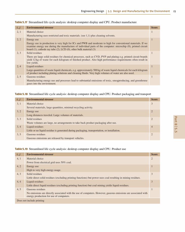
Table 5.17 Streamlined life cycle analysis: desktop computer display and CPU. Product manufacture
i, j Environmental stressor Score
2, 1 Material choice 1
Manufacturing uses restricted and toxic materials. (see 1,1) plus cleaning solvents.
2, 2 Energy use 1
Energy use in production is very high for ICs and PWB and moderate to high for conventional materials. If weexamine energy use during the manufacture of individual parts of the computer: microchip (0), printed circuitboard (1), cathode ray tube (2), LCD (0), other bulk material (3)
2, 3 Solid residues 1
There are large solid residues for chemical processes, such as CVD, PVP and plating e.g. printed circuit boardsyield 12 kg of waste for each kilogram of finished product. Also high performance requirements often result inlow yields.
2, 4 Liquid residues 1
Large quantities of waste liquid chemicals, e.g. approximately 500 kg of waste liquid chemicals for each kilogramof product including plating solutions and cleaning fluids. Very high volumes of water are also used.
2, 5 Gaseous residues 1
Manufacturing energy use and processes lead to substantial emissions of toxic, smogproducing, and greenhousegases into the environment.
Table 5.18 Streamlined life cycle analysis: desktop computer display and CPU. Product packaging and transport
i, j Environmental stressor Score
3, 1 Material choice 3
Several materials, large quantities, minimal recycling activity.
3, 2 Energy use 2
Long distances traveled. Large volumes of materials.
3, 3 Solid residues 2
Waste volumes are large, no arrangements to take back product packaging after use.
3, 4 Liquid residues 4
Little or no liquid residue is generated during packaging, transportation, or installation.
3, 5 Gaseous residues 2
Gaseous emissions are released by transport vehicles.
Table 5.19 Streamlined life cycle analysis: desktop computer display and CPU. Product use
i, j Environmental stressor Score
4, 1 Material choice 2
Power from electrical grid uses 50% coal.
4, 2 Energy use 1
High to very high energy usage.
4, 3 Solid residues 3
Little direct solid residues (excluding printing functions) but power uses coal resulting in mining residues.
4, 4 Liquid residues 3
Little direct liquid residues (excluding printing function) but coal mining yields liquid residues.
4, 5 Gaseous residues 1
No emissions are directly associated with the use of computers. However, gaseous emissions are associated withenergy production for use of computers.
Does not include printing
PartB
5.5

24 Part B Applications in Mechanical Engineering
Table 5.20 Streamlined life cycle analysis: desktop computer display and CPU. Refurbishment/recycling/disposal ratings
i, j Environmental stressor Score
5, 1 Material choice 1
Product contains significant quantities of lead and brominated flame retardants and may contain mercury andcadmium. Often these are not clearly identifiable or easily removable. Many materials are not recycled.
5, 2 Energy use 1
The product is not designed for energy efficiency in recycling, or for high-level reuse of materials. Also, thetransport of recycling is energy intensive because of weight/volume and location of suitable facilities.
5, 3 Solid residues 1
Dissimilar materials are joined together is ways that are difficult to reverse and the product overall is difficult todisassemble. Little recycling. Short life cycle of computers compounds these problems.
5, 4 Liquid residues 3
Product contains no operating liquids and minimal cleaning agents are necessary for reconditioning (not includingprinting functions).
5, 5 Gaseous residues 2
Roasting of printed wiring boards (PWBs) to recycle metals leads to emissions.
Table 5.21 Streamlined life cycle analysis: desktop computer display and CPU. Environmentally responsible productassessment for the computer display and CPU
Life stage Materials Energy Solid Liquid Gaseous Total
Premanufacture 0 1 1 2 1 5/20
Product manufacture 1 1 1 1 1 5/20
Product delivery 3 2 2 4 2 13/20
Product use 2 1 3 3 1 10/20
Recycling 1 1 1 3 2 8/20
Total 7/20 6/20 8/20 13/20 7/20 41/100
in Europe, over brominated flame-retardants, which areused in the plastics.
Currently, there is no complete, up-to-date life cy-cle analysis available for a computer, but an earlierstudy looked at energy, waste, hazardous materials andwater used in the life cycle of a computer worksta-tion [5.21,38], and more-recent information particularlyon the fabrication, use, and end of life stages for a per-sonal computer is given by Kuehr and Williams [5.39].Computers seem to raise concerns at all stages oflife. The premanufacture and manufacturing stages arevery material and energy intensive due primarily to thehigh material purity needed for the microelectronicsfabrication. Distribution can be a concern due to thelarge amount of packing materials and the long dis-tances some products need to travel. The use phasecan be very energy intensive. For example, data givenby Kawamoto [5.40] and Cole [5.41] sets the resi-dential annual energy use for a desktop computer andmonitor at about 380 MJ/y. In a commercial/industrialsetting where the computer monitor may be on con-tinuously, the estimate is 1500 MJ/y. For a three-yearlifetime, this is more than half of the energy used in
production. The end-of-life issues are several; thereare several materials of concern as mentioned earlier,and the shear volume of retired computer and elec-tronics represents a significant solid waste/recyclingchallenge. Currently only a very small percentage ofcomputers are recycled [about 11%, as estimated bythe Environmental Protection Agency (EPA)]. Using thematerials lists given in Table 5.15 and the informationcited in the references reviewed here [5.?, 26, 38–41]we have developed a baseline SCLA for a 1990sdesktop computer and CRT display. The results aregiven in Tables 5.16–5.21. A target plot is given inFig. 5.24.
Using Life Cycle Informationfor Product and Process Improvement
One of the primary reasons for developing life cycle en-vironmental information is to identify opportunities forimprovement. Streamlined life cycle analysis (SLCA) asdeveloped in the two preceding sections is particularlygood at this because it provides an overview with an em-phasis on high-profile issues. The automobile exampleillustrates important environmental improvements from
PartB
5.5

Engineering Design 5.5 Design and Manufacturing for the Environment 25
the 1950s to the 1990s, at the same time indicating sev-eral remaining challenges, particularly related to fossilfuel usage.
The SLCA given for the 1990s desktop computer isintended as a baseline for identifying critical areas forimprovement, which are many. In comparison, the cur-rent laptop computer would score much more favorably.Important improvements would include:
1. a drastic reduction in the total weight of materialsused
2. elimination of significant amount of lead found inthe CRT (although small amounts of mercury areneeded for the laptop display)
3. significantly reduced packing materials4. significantly lower energy required in usage
The SLCA methodology presented here is a com-pact way to learn about a complex problem, however,once a significant target for environmental improvementhas been identified by SLCA, a more quantitative lifecycle inventory for the material(s) of concern would bewarranted. This would allow a much more precise evalu-ation of potential improvements. For example, Fig. 5.22gives the total energy used for a generic family automo-bile in the late 1990s. An LCI study would then connecteach of these energy requirements to the energy technol-ogy used and the corresponding emissions. For examplewhile the use phase burns gasoline in an internal combus-tion engine, the material production and manufacturingphases use a mixture of mostly coal along with natu-ral gas, oil, and even nuclear (from the electricity grid).Hence connecting the energy requirements to the fuelcycles would lead to specific contributions of each typeof pollutant of interest. For example, energy from elec-tricity in the United States comes from 50% coal, 20%
Table 5.22 Energy efficiency guidelines [5.15, 58, 59]
Action Reason
Do SLCA/LCI/LCA for product Identify energy usage
Encourage use of clean renewable energy sources Reduce harmful by-products and preserve resources
Choose the least harmful source or energy Reduce harmful by-products
Note for fossil fuels the cleanest is natural gas followed by oil products,and then coalHave subsystems power down when not in use Reduce energy usage and fossil fuel consumption
Permit users to turn off systems in part or whole Reduce energy usage and fossil fuel consumption
Avoid high energy materials Reduce energy and preserves resources
Avoid high energy processes Reduce energy
Specify best-in-class energy efficiency components Reduce energy usage and fossil fuel consumption
Insulate and /or use waste heat Reduce losses/ increases efficiency
nuclear, 18% natural gas, 7% hydroelectric, 3% oil, and2% renewables. The corresponding emissions per elec-tricity used are: 633 kg CO2/MWh, 2.75 kg SO2/MWh,1.35 kg NOx/MWh, and 12.3 g mercury/GWh, whereMWh is a megawatt-hour, and GWh is a gigawatt-hour [5.42].
A full-blown life cycle analysis (LCA) would in-clude weightings of the different pollutants based onhuman value judgments. For example, the LCA softwareSimapro from the Netherlands employs a weightingscheme called the Eco-indicator that reflects the valuejudgments of Europeans concerning the various envi-ronmental issues that concern them. Obviously suchschemes could vary widely depending upon local con-cerns.
Before leaving this section it is worth noting that,because SLCA yields numerical scores for products, itmight be tempting to compare different types of prod-ucts. This is possible but must be done with caution.In the first place the SLCA methodology developedby Graedel and Allenby was intended as a relativeindicator for a particular product type. Therefore themethodology would have to be modified. A secondproblem is that dissimilar products can have vastlydifferent utilities for the users. Hence the compari-son may seem nonsensical to some. Nevertheless somecomparisons can be useful. For example, Williams haspointed out that the fossil fuel used during the entirelife cycle of the production and use for a computer isalmost identical to that of a refrigerator even thoughthe computer only lasts about one quarter of the time(2.5 y versus 10 y) and the refrigerator is on all ofthe time [5.43]. The obvious implication is that muchmore could be done to improve the energy efficiency ofcomputers.
PartB
5.5

26 Part B Applications in Mechanical Engineering
Table 5.23 Recyclability guidelines [5.15, 58, 60]
Rating Description or action Reason or comment
Good Product is reusable/remanufacturable Extends life of product
Good Materials in part are recyclable with a clearly definedtechnology and infrastructure
Most metals, some plastics in particular: PET & HDPE
Good No toxic materials, or if present, clearly labeled and easyto remove
Avoid Pb, Hg, Cd
Good Allow easy removal of materials, avoid adhesives andjoining methods which can not be reversed
Facilitates separation and sorting
Less good Material is technically feasible to recycle but infrastruc-ture to support recycling is not available
Most thermoplastics, some glass
Less good Material is organic – can be used for energy recovery butcannot be recycled
thermoplastics, rubber, wood products
Avoid Avoid mixtures which cause contamination, and paintingand coatings which are difficult to remove
e.g. polyvinylchloride (PVC) in PET, Cu in steel, paintedplastics
Avoid Material has no known or very limited technology forrecycling
Heated glass, fiberglass, thermoset plastics, compositematerials
5.5.4 Design for the Environment (DFE)
Design for the environment, like design for manufac-turing or design for assembly, is a set of guidelinesto help designers meet particular design goals. Oftenthese guidelines are reduced to simple rules that aidunderstanding. However, behind these rules are obser-vations and models that capture how the product canbe expected to perform as the result of certain designdecisions.
To a certain extent this whole chapter has been aimedat understanding how products and product decisionsresult in environmental loads. There can be, however,different environmental goals. For example, designingan automobile for lower fuel consumption may lead tousing structural composite materials for weight reduc-tion, whereas designing for recyclability would probablylead to the use of metals for the structural components.In this section we outline some of the generally agreedupon guidelines for two important environmental goals:reduced hydrocarbon fuel consumption and increasedrecyclability. These are summarized in Tables 5.22 and5.23.
5.5.5 System-Level Observations
In this chapter we have presented an overview of engi-neering actions to lessen the impact of materials use,manufacturing, and design decisions on the environ-ment. One of the goals of this chapter has been toidentify the connections between a product life cycle andthe associated environmental loads. To do this we havefrequently normalized the environmentally sensitive pa-
rameters such as energy requirements or emissions bysome measure of useful output such as the weight ofthe output, the economic activity, or, in some cases,just by the product itself. This scheme helps assign re-sponsibility and allows us to track progress by enablingcomparisons.
At the same time, however, by measuring the envi-ronmental load too narrowly there is a danger of missingthe overall trend. One way of making this point is bywriting the environmental impact in terms of severalnormalized parameters. For example, consider
impact = populationwealth
person
impact
wealth. (5.2)
This is a mathematical identity, known as the IPATequation, which associates impact I , with three im-portant elements: P for population, A for affluenceand T for technology. Our focus has been on the lastterm – impact/wealth (or impact/product etc.). Manyvariations on the IPAT equation are possible, for ex-ample A = products/person, T = impact/product, etc.It is the collection of the terms on the right-hand sidethat give the impact. Hence, a technology improve-ment could be offset by increases in population and/orwealth/person. This is unfortunate, but appears not tobe in the domain of the engineer. If this was all therewas to the story, the IPAT equation would be a neat wayto subdivide responsibility. The implication is that, ifengineers can improve the technology term, then theyhave done their job. The actual picture unfortunately ismuch more complicated, as technology improvementsdo not only improve the environment but also play animportant role in stimulating the economy. In fact, rela-
PartB
5.5

Engineering Design 5.6 Failure Mode and Effect Analysis for Capital Goods 27
5.6 Failure Mode and Effect Analysis for Capital Goods
Failure mode and effect analysis (FMEA) [5.47, 48])is a method to recognize and eliminate mistakes orcauses of faults during the product design process andin particular in the earliest stages.
This method was developed in 1963 by the Na-tional Aeronautics and Space Agency (NASA) withinthe Apollo mission to design products without designfailures. This is especially important when products can-not be repaired easily, e.g., satellites or spaceships. Themethod was adopted later by the aviation industry, theautomotive industry, in medicine and nuclear technol-ogy as well as by the armaments industry [5.48, 49].Today this method is increasingly used in all fieldsof the development process of consumer and capitalgoods [5.47, 50–52].
With regard to the rework of the initially developedand applied approach see [5.52, 53].
5.6.1 General Innovationsfor the Application of FMEA
The complexity of many products due to their mecha-tronic character but also because of the simultaneouslyapplied engineering concepts complicates the distinc-tion between the three traditional types of FMEA:system FMEA, the design FMEA and process FMEA(Fig. 5.25). In addition many FMEA sessions mix allthree fields [5.53].
Process-FMEA
Design-FMEA
System-FMEA
Proceed of development
Fig. 5.25 FMEA separated in subprocesses (traditionalform)
FMEA-process
Continuous influx of entities
Sporadic or planned FMEA sessions – updates
Fig. 5.26 FMEA as a continuous process
Instead of this distinction a continuous form ofFMEA therefore has to be implemented, which becomesmore detailed with increasing knowledge through theproduct development process. As the design of a productproceeds and product knowledge grows, the danger oferrors increases as does the need for their recognition andelimination. This leads to the concept of a continuousFMEA process (Fig. 5.26).
Such continuity produces the best results if thegroup of people involved stays the same. In practice,it turns out that it is already reasonable to apply com-petence in manufacturing or quality control in FMEAat the concept stage. This does not contradict the de-mand that specialists have to be consulted for specificquestions. An additional benefit is gained from allteam members becoming acquainted with the prod-uct.
In general the early stages of the product de-velopment process and the stages during and aftermarket launch are not covered by traditional FMEA.The early phases of the product development pro-cess (idea generation and market assessment) includemany sources of errors that influence the successor failure (not only technically) of a new prod-uct.
The traditional form of FMEA does not take the costsof possible damage as well as the costs of avoiding thisdamage into account. To decide on appropriate trouble-shooting actions it is important to gain an economicunderstanding of FMEA and its consequences.
The new form, based on the original FMEA form butnow including the economic point of view, is schema-tized and formalized in Fig. 5.27.
5.6.2 General Rules to Carry Out FMEA
The observation of FMEA sessions in companies showsthat a clear separation into the three fields of system,design and process is not performed, nor is it reason-able. This is because each failure affects the system, thedesign, and the process FMEA.
Since the system FMEA is carried out before thedesign FMEA this new influence into the system andhis effects is not considered anymore. Only a completedprocess FMEA will discover the actual source of error,for example an unsuitable die-casting machine. Againthe influence of the elimination of this failure mechanismis no longer considered in the system and design FMEAs.
PartB
5.6

28 Part B Applications in Mechanical Engineering
Companyproject
Failure mode and effect analysis – FMEA
Project- and lifecycle – FMEA
FailurelocationIdent-No.Entity
Type offailure
Impact offailure
Cause offailure
Present status
Means ofcontrol
Name of functions / working principles /assemblies
Ident-No.
Generated by: Date:Generating department:
Remedialaction
Improved status
Realizedaction
A B E K RPZ A B E K* RPZ*
6 7 8 9 10 13 14 15 16 1754321 11 12
Fig. 5.27 FMEA form with additional columns K and K∗ to consider the cost influences for decision-making
For these reasons it is not reasonable to separate thethree individual FMEA methods. It is more reasonableto carry them out simultaneously in order to benefit fromsynergy within the group.
The Prerequisites at the Beginning of a FMEAThe following prerequisites must be met absolutely atthe beginning of an FMEA process.
1. FMEA participants that are competent and con-firmed in their continuity [5.54, 55]. The definitionof the risk priority number (RPZ) numbers (seeSect. 5.6.3) is done subjectively and thus randomly.Therefore the selection of the FMEA participantshas to be done carefully in order to take into accountdifferent views and issues and to obtain a realisticRPZ. This problem is similar to that of the evaluationprocess [5.54, 55].
Operate View HearAction
Amplify Shine RingFunction
Hydraulic Electric AcousticPrinciple
Staticpressure
Ohm’s law Sound waveEffect,physical principle
P2 = P1(A2 /A1) U = R I E = J/(f λ)Formula
Examples
Fig. 5.28 Heuristic context within the product develop-ment process; the five stages of solution finding in theconcept stage
2. The product idea is defined and understood by allFMEA participants.
3. The market performance process of a new productis available.
4. A clear list of demands (requirements), tested forinterrelations [5.56].
5. A use analysis [5.57].6. A functional analysis, if possible as a functional
diagram.7. Heuristic context within the product development
process. The methods involved between the indi-vidual components and units as well as external(referring to the usage of a product) and internal(working principles, effects and regularities) func-tions (Fig. 5.28) cannot be correctly represented inconventional forms, which will result in incorrectdecisions.
8. Complete documentation of the state of develop-ment.
Improvement of Error Recognition(Formal) FMEA with conventional forms [5.47] is inprinciple incomplete since a suitable inspection of com-pleteness is not given. This takes effect on the methodiccontext and on the other hand on the accidental errorrecognition. Some ways of improving error recognitionrates are
1. The experience of the FMEA participants2. Integration of other specialists3. Knowledge of or becoming acquainted with the
product to be analyzed
PartB
5.6

Engineering Design 5.6 Failure Mode and Effect Analysis for Capital Goods 29
4. Integration of customer-oriented departments andthe customers themselves
5. Collection and analysis of mistakes and experiencesrecorded in databases
6. Study of the history of a product (test reports, com-plaint reports etc.);
7. Concurrent application of heuristic support tools(e.g., Goldfire, Invention Machine, Boston)
Inclusion of all Secondary Fieldsof Development
The FMEA refers only to hardware, not to docu-mentation, services, software logistics, test programs,manufacturing method, production plants and machines.Measurement and checking facilities, experimental se-tups and devices are not covered by any FMEA, althoughmany errors could occur here. This situation only can beimproved by including these new fields.
5.6.3 Procedure
The localization of risks concerning the lifetime ofa product, starting from the first design concept toproduct use, is in principle always the same procedure,regardless of the product size. The principle and proce-dure is identical for a small product like a plug-in contact(Fig. 5.29) or a large technical system like a machine tool(Fig. 5.30).
Description of the project.
Nomination of the FMEA moderator. The nomination isdone with agreement of the responsible project manager.
Formation of an FMEA team. The formation of theteam (Table 5.24) is done by the project manager withagreement of the FMEA moderator. Important is thevisualization of the team members in a form. The
Table 5.24 Visualization of the team members in a form
No. Faculty/customer Name, company
1 Project management
2 Design, construction and calculation
3 Manufacturing preparation
4 Manufacturing
5 Quality control, simultaneously presentation of FMEA
6 Purchase department
7 Sales department
8 Customer support (inauguration, maintenance, repair)
Fig. 5.29 Small product: plug-in contact (source: ABB,Baden)
Fig. 5.30 Large product: machine tool (source: A. Breiing,MIKRON, Biel)
following departments should contribute at least oneparticipant as a continuous FMEA team member.
Structuring of functions. The basis of FMEA is func-tional analysis of the investigated product. Thisimplicates the specification of functional modules or
PartB
5.6

30 Part B Applications in Mechanical Engineering
Lock
Close Seal Open
Move Position Lock Unlock Move
Fig. 5.31 Example of a hierarchical functional structure ofan autoclave door [5.62]
submodules, for example as a hierarchical functionaldiagram (Fig. 5.31) or as a process-orientated diagram(Fig. 5.32).
Filling out the FMEA form (Fig. 5.27).
Column 1. This column consists of all aspects of possi-ble sources of error, as shown in Table 5.25. Since in theearly stages of product development, in particular duringidea generation and during the determination of the mar-ket performance profile, sources of error can already bedetected, the corresponding entities have to be enteredin this column (first block). Sources of error can also bedetected in the development phase (second block), dur-ing market launch (third block), and in particular duringthe usage phase up to product disposal (fourth block).
Column 2–4. This columns require an analysis of allpossible potential failures, for example:
Possible errors in the planning stage.
Integrate motoric and muscular drive
Integrate locking mechanism
Take into operation locking mechanism
Create locking force and movement
Transfer locking force and movement
Transfer opening force and movement
Create force for opening and movement
Seal autoclave door
Integrate gasket
Inspect locking mechainsm and gasket
Inner process
Outer process
Autoclavedoor open
Auto-clavedoorclosed
En-viron-ment
Autom.drive
Men
Material
Energy
ES
S
E
Inf.
I
Fig. 5.32 Example of a process functional structure of an autoclave door [5.62], generated from Fig. 5.30
• The idea of a new product cannot be realized dueto physical, chemical, biological, ethical, legal orcultural constraints or restrictions.• The product idea is already realized by competitors.• The product idea is already protected by the com-petitors with patents, petty patents and/or designpatents.• There is no market potential and/or no market gapavailable.• The time is not ripe.• No foe image available or not relevant enough (formilitary development).• Rare resources.• No sustainable environment.
Possible errors in the development process.
• Internal functions from a function analysis (hierar-chical and/or process functional structure)• External functions from a use analysis• Assembly of the product structure• Assembly/disassembly:– Assembly/disassembly operation– Assembly/disassembly regulations– Utilities (e.g., oil for the removal of bearings)– Assembly/disassembly devices– Control and/or measuring devices (e.g., torque
spanner)– Additional means (z. B. hoisting devices)• Components from the product structure and/or partslist• Manufacturing:– Manufacturing processes (e.g., lapping)
PartB
5.6

Engineering Design 5.6 Failure Mode and Effect Analysis for Capital Goods 31
Table 5.25 FMEA form with entities over the complete life cycle of a product (an example)
Company Failure mode and effect analysis (FMEA)Project
Failure location Impact of failure Type of failure Failure cause Means of controlIdentification numberEntity1 2 3 4 5IdeaMarket analysisCost planningTime schedulingStrategyInner functionsOuter functionsModuleAssemblyComponentManufacturing processStorageTransportMountingInitiationImplementingOperationControllingMaintenanceRepairRecycling or liquidation
– Manufacturing operations (for manual manufac-turing, e.g., deburring)
– Manufacturing regulations– Manufacturing means and devices (e.g., drilling
patterns)– Auxiliary manufacturing requirements (e.g.,
coolant)– Control and measuring devices (e.g., calipers).
The Outer function takes into account the human be-ing in his incompleteness as users during the product lifemust be included into the FMEA. The user is a compo-nent of the system, he influences all processes, startingfrom idea generation, through development and usageuntil the end of the product life. The user causes failuresand errors at all stages. With the integration of the avail-able use analysis (Table 5.26) that covers all stages ofa product’s life [5.57] possible sources of error duringassembly, maintenance and repair are also considered(Table 5.25, fourth block).
In order to register these potential sources of errorsystematically the FMEA is expanded by the integration
of the use analysis. These entities can be taken from thetabular recording of the man–machine interfaces.
Moreover each part, assembly and product needs thefollowing documentation:
Possible errors within the technical documentation.Check the:
• manufacturing documents (drawings and lists)• documents for assembly/disassembly (e.g., instruc-tion sheets)• calculation documents, such as– load assumptions– verification of strength– verification of deformation– verification of stability (e.g., buckling, bending,
stability)• Balances such as– balance of performance– balance of weight– position of the centers of gravity– balance of the moments of inertia
PartB
5.6

32 Part B Applications in Mechanical Engineering
Table 5.26 Use analysis of a nutcracker (example)
No. Subfunctionfirst order
Man–productrelationship:needed activities
Man–machine interface Affiliated requirement Required functionsresp. possible carriersof function
1 Detection Nutcracker: Eye – object Noticable design Color
(of the object) Seek Sense of touch – object Recognizable design Contrast
Ask for Shiny color Grade of reflection
Find
2 Transporting/ Nutcracker: Hand – handle Little weight, ergonomic handle, Lightweight construction
placing Grasp, lift, carry Hand – object body handy surfaces, Handle – leverage
(the object) Put down Eye – hand – handle crack protection Corrugated surface
Slacken Stable stand Platform
3 Equipment Open nutcracker Hand – object Easy to equip Trough
(with a nut) Insert nut Hand – nut Safely to equip Stop
4 Locating Hold nut Finger – nut Easy to use Trough
(of the nut) Press against stop Hand – nut Sure hold of nut Clamping claw
Clamp nut Eye – finger – nut Limit clamping force Vise
5 Produce Move leverage Hand – leverage Sure force insertion Handle
(opening) force Hit against anvil Fist – anvil Notice finger/hand-span Leverage
Turn knob Hand/finger – knob
6 Guide force/ Inner function /. Force amount [N] Leverage
amplify force Distance amount [mm] Spline
Limit force/distance Screw
7 Nut opens by: Inner function /. Selection of effective functional- Thrust piece
· pressure ities that can be cheaply realized Splines
· effect of spline Blade
Clamping screw
8 Remove Remove cracked nut Finger – crecked nut Easy to remove Collecting pan, sack
(result) Remove nut and shell Hand – cracked nut Sure to remove Basin
Eye – finger – cracked nut Flap
Opening
9 Cleaning Hold nutcracker Hand – nutcracker Easy to handle Room design
Shake out crack room Finger/hand – No unreachable corners Shape of surface
Clean crack room cleaning device Easy to clean surface Surface roughness
– balance of temperature– balance of coolant• Documents such as– manufacturing documents– instruction sheets– instructions for maintenance and service– spare-part catalogue
Possible errors during market launch.
• Storage– Activities– Apparatus (e.g., bearing block)– Racks, halls, stacks (e.g., storage rooms with air
conditioning)• Transport
– Activities– Apparatus (e.g., lifting gear)– Means of transportation (e.g., overhead crane)• Mounting– Activities– Mounting regulations and instructions– Apparatus (e.g., lifting gear)– Measuring and test equipment (e.g., theodolite)• Initial operation:– Activities and tests in accordance with
· Instruction manual (Chapter Initial setup)· Checklist· User’s handbook· Maintenance instruction
PartB
5.6

Engineering Design 5.6 Failure Mode and Effect Analysis for Capital Goods 33
Possible errors in the use stage and in decommissioning.
• Initial operation:– Activities in accordance with
· Instruction manual (Chapter Initial setup)· Checklist· Maintenance history· Document• Operating:
– Activities in accordance with· Instruction manual· User’s handbook• Maintenance:
– Activities and test in accordance with· Instruction manual· User’s handbook· Service documentation· Maintenance history (e.g., exhaust gas doc-
ument for a motor vehicle)• Service:– Activities and test in accordance with
· Instruction manual· User’s handbook· Service manual and Spare part catalogue· Logistics documents (e.g. global workshop
catalogue)
Column 5. Here the status of currently used measures forthe prevention of failures and test procedures is entered.These entries are used to reduce the causes of failure incolumn 4 and to detect possible sources of error.
Columns 6–10. These columns are used to calculate therisk priority number (RPZ).
To decide about actions for trouble-shooting it isvery important to obtain an economic perspective onFMEA and its consequences. In the case of extensionof the FMEA by integrating a cost calculation, the formincludes an additional column K for the costs. The factorK stands for the probable costs in the case of an erroroccurring.
The value of column 10 has to be calculated by
RPZ = A · B · E · K (5.3)
where:A = Probability of a failure incidence
Unlikely 1Very low 2Low 3
Medium 4High 5Very high 6
B = Consequences for the customer
Consequences not noticeable 1Inconsiderable inconvenience for the customer 2Small inconvenience for the customer 3Inconvenience for the customer 4Irritation of the customer 5Possible loss of the customer 6
E = Probability of failure detection
Very high 1High 2Medium 3Low 4Very low 5Unlikely 6
K = Probability costs in case of a fulfilled error
No or negligible increase of costs 1Little additional costs 2Medium additional costs 3High additional costs 4Extremely high additional costs 5Non-budgeted costs 6
Instead of the absolute measure of 1–6 a range ofvalues from 1–10 can also be chosen. This is only rea-sonable if detailed knowledge is available, for examplewithin an FMEA at the end of the product developmentprocess.
A verbal description of the RPZ is:
Unacceptable high 1296–10 000Medium 256–1296Low 1–1
In practice RPZ failure values lower than 81 resp.625 are not used to remove a failure as it is not profitableto do so.
Column 11. In this column the actions for trouble-shooting are entered.
Columns 12–17. Supposing that the recommended ac-tions for trouble-shooting from column 11 are realizedthe actions are described in columns 12 and the RPZ∗value is calculated again in columns 13–17. The factorK∗ stands for the probable costs of the measure requiredto avoid or minimize a probable error. Both K and K∗
PartB
5.6
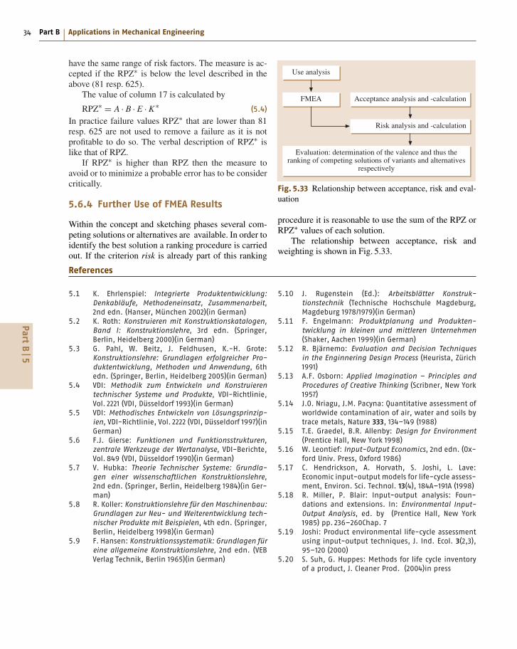
34 Part B Applications in Mechanical Engineering
have the same range of risk factors. The measure is ac-cepted if the RPZ∗ is below the level described in theabove (81 resp. 625).
The value of column 17 is calculated by
RPZ∗ = A · B · E · K∗ (5.4)
In practice failure values RPZ∗ that are lower than 81resp. 625 are not used to remove a failure as it is notprofitable to do so. The verbal description of RPZ∗ islike that of RPZ.
If RPZ∗ is higher than RPZ then the measure toavoid or to minimize a probable error has to be considercritically.
5.6.4 Further Use of FMEA Results
Within the concept and sketching phases several com-peting solutions or alternatives are available. In order toidentify the best solution a ranking procedure is carriedout. If the criterion risk is already part of this ranking
Use analysis
Acceptance analysis and -calculation
Risk analysis and -calculation
Evaluation: determination of the valence and thus theranking of competing solutions of variants and alternatives
respectively
FMEA
Fig. 5.33 Relationship between acceptance, risk and eval-uation
procedure it is reasonable to use the sum of the RPZ orRPZ∗ values of each solution.
The relationship between acceptance, risk andweighting is shown in Fig. 5.33.
References
5.1 K. Ehrlenspiel: Integrierte Produktentwicklung:Denkabläufe, Methodeneinsatz, Zusammenarbeit,2nd edn. (Hanser, München 2002)(in German)
5.2 K. Roth: Konstruieren mit Konstruktionskatalogen,Band I: Konstruktionslehre, 3rd edn. (Springer,
Berlin, Heidelberg 2000)(in German)
5.3 G. Pahl, W. Beitz, J. Feldhusen, K.-H. Grote:
Konstruktionslehre: Grundlagen erfolgreicher Pro-duktentwicklung, Methoden und Anwendung, 6th
edn. (Springer, Berlin, Heidelberg 2005)(in German)
5.4 VDI: Methodik zum Entwickeln und Konstruierentechnischer Systeme und Produkte, VDI-Richtlinie,
Vol. 2221 (VDI, Düsseldorf 1993)(in German)
5.5 VDI: Methodisches Entwickeln von Lösungsprinzip-ien, VDI-Richtlinie, Vol. 2222 (VDI, Düsseldorf 1997)(in
German)
5.6 F.J. Gierse: Funktionen und Funktionsstrukturen,zentrale Werkzeuge der Wertanalyse, VDI-Berichte,
Vol. 849 (VDI, Düsseldorf 1990)(in German)
5.7 V. Hubka: Theorie Technischer Systeme: Grundla-gen einer wissenschaftlichen Konstruktionslehre,
2nd edn. (Springer, Berlin, Heidelberg 1984)(in Ger-
man)
5.8 R. Koller: Konstruktionslehre für den Maschinenbau:Grundlagen zur Neu- und Weiterentwicklung tech-nischer Produkte mit Beispielen, 4th edn. (Springer,
Berlin, Heidelberg 1998)(in German)
5.9 F. Hansen: Konstruktionssystematik: Grundlagen füreine allgemeine Konstruktionslehre, 2nd edn. (VEB
Verlag Technik, Berlin 1965)(in German)
5.10 J. Rugenstein (Ed.): Arbeitsblätter Konstruk-tionstechnik (Technische Hochschule Magdeburg,
Magdeburg 1978/1979)(in German)
5.11 F. Engelmann: Produktplanung und Produkten-twicklung in kleinen und mittleren Unternehmen(Shaker, Aachen 1999)(in German)
5.12 R. Bjärnemo: Evaluation and Decision Techniquesin the Enginnering Design Process (Heurista, Zürich
1991)
5.13 A.F. Osborn: Applied Imagination – Principles andProcedures of Creative Thinking (Scribner, New York
1957)
5.14 J.O. Nriagu, J.M. Pacyna: Quantitative assessment of
worldwide contamination of air, water and soils by
trace metals, Nature 333, 134–149 (1988)
5.15 T.E. Graedel, B.R. Allenby: Design for Environment(Prentice Hall, New York 1998)
5.16 W. Leontief: Input-Output Economics, 2nd edn. (Ox-
ford Univ. Press, Oxford 1986)
5.17 C. Hendrickson, A. Horvath, S. Joshi, L. Lave:
Economic input-output models for life-cycle assess-
ment, Environ. Sci. Technol. 13(4), 184A–191A (1998)
5.18 R. Miller, P. Blair: Input-output analysis: Foun-
dations and extensions. In: Environmental Input-Output Analysis, ed. by (Prentice Hall, New York
1985) pp. 236–260Chap. 7
5.19 Joshi: Product environmental life-cycle assessment
using input-output techniques, J. Ind. Ecol. 3(2,3),
95–120 (2000)
5.20 S. Suh, G. Huppes: Methods for life cycle inventory
of a product, J. Cleaner Prod. (2004)in press
PartB
5

Engineering Design References 35
5.21 T.E. Graedel: Streamlined Life-Cycle Assessment(Prentice Hall, New York 1998)
5.22 Environmental Protection Agency: EPA TRI 1998 DataRelease Web Page (EPA, Washington 1998)(www.epa.
gov/tri/tri98/index.htm)
5.23 V. Smil: Energies – An Illustrated Guide to the Bio-sphere and Civilization (MIT Press, Cambridge 1999)
5.24 K.J. Martchek, E.S. Fisher, D. Klocko: Alcoa’s world-
wide life cycle information initiative, Proc. Total Life
Cycle Conference – Land, Sea and Air Mobility, SAE
International P-339, 121–125 (1998)
5.25 P.F. Chapman, F. Roberts: Metals Resources and En-ergy (Butterworth-Heinemann, London 1983)
5.26 E. Williams, R. Ayres, H. Heller: The 1.7 kg microchip:
Energy and chemical use in the production of semi-
conductors, Environ. Sci. Technol. 36(24), 5504–5510
(2002)
5.27 J. Dahmus, T. Gutowski: An environmental analysis
of machining. In: ASME Int. Mechanical EngineeringCongress, ed. by (ASME, New York 2004)
5.28 S. Dalquist, T. Gutowski: Life cycle analysis of con-
ventional manufacturing techniques: Sand casting.
In: ASME Int. Mechanical Engineering Congress, ed.
by (ASME, New York 2004)
5.29 J. Sherman, B. Chin, P.D.T. Huibers, R. Garcia-Valls,
T.A. Hatton: Solvent replacement for green process-
ing, Environ. Health Persp. 106, 253–271 (1998)Suppl.
1
5.30 V.M. Thomas, T.G. Spiro: The U.S. dioxin inventory:
Are there missing sources?, Environ. Sci. Technol.
30(2), 82A–85A (1996)
5.31 A. Grubler: Technology and Global Change (Cam-
bridge Univ. Press, Cambrigde 1998)
5.32 G.A. Keoleian, K. Kar, M.M. Manion, J.W. Bulkley:
Industrial Ecology of the Automobile: A Life CyclePerspective (Society of Automotive Engineers, War-
rendale 1997)
5.33 J.L. Sullivan, R.L. Williams, S. Yester, E. Cobas-Flores,
S.T. Chubbs, S.G. Hentges, S.D. Pomper: Life cycle
inventory of a generic US family sedan – Overview
of results USCAR AMP project. In: SAE International,ed. by 1998 Total Life Cycle Conference Proc., (, 1998)
pp. 1–14paper 982160
5.34 H. Maclean, L. Lave: A life-cycle model of an au-
tomobile, Environ. Sci. Technol. 32(13), 322A–329A
(1998)
5.35 T.E. Graedel, B.R. Allenby: Industrial Ecology and theAutomobile (Prentice Hall, New York 1998)
5.36 J.M. DeCicco, M. Thomas: A method for green rating
of automobiles, J. Ind. Ecol. 3(1), 55–75 (1999)
5.37 M.A. Weiss, J.B. Heywood, E.M. Drake, A. Schafer,
F.F. AuYeung: On the Road in 2020, Energy Labora-
tory Report MIT EL 00-003 (MIT, Cambridge 2000)
5.38 Microelectronics, Computer Technology Corporation:
Life Cycle Assessment of a Computer Workstation,
Report HVE-059-094 (MCC, Austin 1994)
5.39 R. Kuehr, E. Williams (Eds.): Computers and theEnvironment Understanding and Managing theirImpacts (Kluwer Academic, Dordrecht 2004)
5.40 K. Kawamoto, J. Koomey, B. Nordman, A. Meier:
Electricity used by office equipment and net-
work equipment in the U.S.. In: Conf. En-ergy Efficiency in Buildings, ed. by (EPA,
Lawrence Berkeley National Laboratory, Berke-
ley 2000)(http://enduse.lbl.gov/projects/Indo/Puba.
html)
5.41 D. Cole: Energy consumption and personal com-
puters. In: Computers and the Environment: Un-derstanding and Managing Their Impacts, ed. by
R. Kuehr, E. Williams (Kluwer Academic, Dordrecht
2003) pp. 131–159
5.42 Environmental Protection Agency: EPA egrid 2004(EPA, Washington 1998)(www.epa.gov/cleanenergy/
egrid/index.htm)
5.43 E. Williams: Environmental impacts in the produc-
tion of personal computers. In: Computers and theEnvironment: Understanding and Managing TheirImpacts, ed. by R. Kuehr, E. Williams (Kluwer Aca-
demic, Dordrecht 2004) pp. 41–72
5.44 R.M. Solow: Technical change and the aggregate
production function, Rev. Econ. Statist. 39, 312–320
(1957)
5.45 E. Williams: The Elusive Quest for Growth:Economists’ Adventures and Misadventures in theTropics (MIT Press, Cambridge 2002)
5.46 W.S. Jevons: The Coal Question: An Inquiry Concern-ing the Progress of the Nation, and the ProbableExhaustion of our Coal-mines, Reprints of Economic
Classics (Kelley, Fairfield 1906)
5.47 DIN: Ausfalleffekt-Analyse, DIN 25448 (Beuth, Berlin
1978)(in German)
5.48 Procedures for Performing a Failure Mode, Effectsand Criticality Analysis (FMECA), MIL Std. 1629A (Mil-
itary Standard, Washington 1980)
5.49 P. Conrad, P.E. Hedderich: Navy Proactive Mainte-nance (US Navy, Washington 2000)
5.50 N. Berens: Anwendung der FMEA in Entwicklung undProduktion (Verlag Moderne Industrie, Landsberg
1989)(in German)
5.51 Kepner, Tregoe: Entscheidungen vorbereiten undrichtig treffen (Verlag Moderne Industrie, Landsberg
1988)(in German)
5.52 M. Schubert: FMEA – Fehlermöglichkeits- und Ein-flußanalyse (Deutsche Gesellschaft für Qualität,
Frankfurt 1993)(in German)
5.53 A. Breiing: Die FMEA in sinnvoller Form für Investi-tionsgüter (Institut für Mechanische Systeme, ETH
Zürich 2003)(in German)
5.54 A. Breiing: The evaluators influence on the results of
evaluation. In: First Int. Workshop on MulticriteriaEvaluation, ed. by (, Neukirchen 2000)
5.55 A. Breiing: Who evaluate the evaluators?. In: Int.Conf. Computer Integrated Manufacturing, ed. by (,
Zakopane 2001)
PartB
5
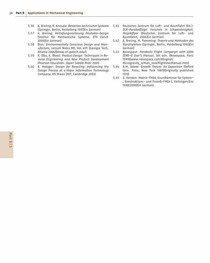
36 Part B Applications in Mechanical Engineering
5.56 A. Breiing, R. Knosala: Bewerten technischer Systeme(Springer, Berlin, Heidelberg 1997)(in German)
5.57 A. Breiing: Vertiefungsvorlesung Produkte-Design(Institut für Mechanische Systeme, ETH Zürich
2000)(in German)
5.58 Bras: Environmentally Conscious Design and Man-ufacture, Lecture Notes ME, Vol. 4171 (Georgia Tech,
Atlanta 2004)(www.srl.gatech.edu/)
5.59 K. Otto, K. Wood: Product Design: Techniques in Re-verse Engineering and New Product Development(Pearson Education, Upper Saddle River 2001)
5.60 B. Metzger: Design for Recycling: Influencing theDesign Process at a Major Information TechnologyCompany, MS Thesis (MIT, Cambridge 2003)
5.61 Deutsches Zentrum für Luft- und Raumfahrt (Ed.):
DLR-Parabelflüge: Forschen in Schwerelosigkeit,Projektflyer (Deutsches Zentrum für Luft- und
Raumfahrt, 2006)(in German)
5.62 A. Breiing, M. Flemming: Theorie und Methoden desKonstruierens (Springer, Berlin, Heidelberg 1993)(in
German)
5.63 Novespace: Parabolic Flight Campaign with A300ZERO-G User’s Manual, 5th edn. (Novespace, Paris
1999)(www.novespace.com/VEnglish/
Microgravity_a/man_vola/flightUserManual.htm)
5.64 R.M. Solow: Growth Theory: An Exposition (Oxford
Univ. Press, New York 1987)(Originally published
1970)
5.65 G. Kersten: Matrix-FMEA, Grundseminar für System-
, Konstruktions- und Prozeß-FMEA (, Vaihingen/Enz
1998/2000)(in German)
PartB
5

1493
About the Authors
Gritt Ahrens Chapter B.13, Sect. 13.2
Daimler AG X944Systems Integration and Comfort ElectricSindelfingen, [email protected]
Gritt Ahrens received the PhD degree from the Department of Engineering Designand Methodology at the Technical University of Berlin. She developed a methodfor capture and management of product requirements and substantiated its practicalapplicability. Since 2001 she has been developing and optimizing various processes inthe context of car development at Mercedes-Benz Cars Development (Daimler AG).
Seddik Bacha Chapter C.17, Sect. 17.4
Université Joseph FourierGrénoble Electrical EngineeringLaboratoryGrenoble, [email protected]
Professor Seddik Bacha received the Engineering and Magister degree from ÉcoleNationale Polytechnique of Algiers in 1982 and 1990, and the PhD and HDR degreesin 1993 and 1998 from Polytechnic Institute of Grenoble, France, respectively. Heis presently the manager of the Power System Group in the Grénoble ElectricalEngineering Laboratory and Professor at the Université Joseph Fourier, Grenoble. Hisinterests are power electronics systems, power quality, and renewable energy.
Stanley Baksi Chapter C.18
TRW Automotive, Lucas Varity GmbHKoblenz, [email protected]
Stanley Baksi received the BA degree in Engineering in 2000 fromVisvesvaraya National Institute of Technology and the MSc in Me-chanical Engineering from California State University, Long Beach. Hecompleted his doctoral research on rapid bone reconstruction using re-verse engineering at Otto-von-Guericke University, Magdeburg, in 2007.Since January 2008 he has been a Project Engineer with TRW Automo-tive providing computer-aided engineering support for the development ofautomotive brakes.
Thomas Böllinghaus Chapter B.7, Sect. 7.4.8
Federal Institute for Materials Researchand Testing (BAM)Berlin, [email protected]
Professor Thomas Böllinghaus received the Dr.-Ing. degree in 1995from the Helmut-Schmidt-University, Hamburg, and qualified there asa Professor for Materials Science and Welding Technology in 1999. Hethen became head of Division V.5 Safety of Joined Components at theFederal Institute for Materials Research and Testing (BAM), Berlin.Since 2003 he has been Vice President of BAM and became HonoraryProfessor for Failure Analysis and Failure Prevention in the Facultyfor Mechanical Engineering at the Otto-von-Guericke University,Magdeburg in 2008. His research interests focus on hydrogen-assistedcracking of structural metallic materials, numerical simulation ofhydrogen transport and cracking, hot cracking phenomena in welds, andfailure analysis and lifecycle evaluations of joined components.
Alois Breiing Chapter B.9, Sect. 9.6
Eidgenössische Technische HochschuleZürich (ETH)Institut für mechanische Systeme (IMES)Zentrum für Produkt-Entwicklung (ZPE)Zurich, [email protected]
Alois Breiing is a retired Professor (Titularprofessor) at ETH Zürich. He was a Lecturer(Privatdozent) at the Institute of Mechanical Systems. He has 23 years of experienceas an aerospace engineer in the Development and Design Department of the aerospacecompany Dornier. Beginning in 1985 he worked at the Institute of Design andConstruction Methods of ETH Zurich (now the Institute of Mechanical Systems),starting as a Senior Researcher and Section Leader. He received a doctor’s degree in1991. He gave lectures in machine design. The main topics of his research work wereevaluation and decision processes.

1494 About the Authors
Eugeniusz Budny Chapter B.14, Sect. 14.1
Institute of Mechanized Construction andRock MiningWarsaw, [email protected]
Dr. Eugeniusz Budny is a Professor of Mechanical Engineering and Emeritus Directorof the Institute of Mechanized Construction and Rock Mining (IMBiGS) in Warsaw,Poland. He began his career as an automotive industry product designer and then movedto the construction equipment manufacturing industry, specializing in the design ofsingle-bucket excavators, hydraulic drives, and hydraulic engineering machinecontrols. Since 1977 he has been engaged in the mechanization of construction work.Professor Budny served as President of the International Association for Automationand Robotics in Construction (IAARC) and has been Chair of ISO/TC 195 and thePolish Committee for Standardization in the field of building construction machinerysince 2005.
Gerry Byrne Chapter B.7, Sects. 7.3.1, 7.3.2
University College DublinSchool of Electrical, Electronic andMechanical EngineeringBelfield, Dublin 4, [email protected]
Gerry Byrne F.R.Eng. is the Professor of Mechanical Engineering andDirector of the Advanced Manufacturing Science Research Centreat University College Dublin (UCD), Ireland. He has over 30 yearsof experience with high-precision manufacturing processes, surfaceengineering, and aspects of surface microstructuring. He is an expertin the field of cutting processes and has published extensively. He isa Fellow of the International Academy for Production Engineering (CIRP)and a Member of the Council of that Academy. He is an InternationalFellow of the Royal Academy of Engineering, UK, and of the Society ofManufacturing Engineers, USA.
Edward Chlebus Chapter B.7, Sect. 7.5
Wrocław University of TechnologyCentre for Advanced ManufacturingTechnologiesWrocław, [email protected]
Professor Edward Chlebus is Director of the Institute of ProductionEngineering and Automation at Wrocław University of Technology,Poland, and the Head of the Centre for Advanced Manufacturing Tech-nologies (CAMT). His main research areas are design methodology andCAx and PDM/PLM systems, rapid prototyping, reverse engineering,modeling, optimization, and simulation of production processes. He isa Contractor for six International Projects in FP6, Leonardo da Vinci,and ERA Net. He is also a Graduate of the University of ConnecticutBusiness School.
Mirosław Chłosta Chapter B.14, Sect. 14.1
IMBiGS – Institute for MechanizedConstruction and Rock Mining (IMBiGS)Warsaw, [email protected]
Miroslaw Chlosta received the M.S. degree from Warsaw Technical University in1980. In that year he began work at IMBiGS as a Research Associate. He received thePhD degree from IMBiGS in 2003 and was an Assistant there from 2003 onwards. Hisresearch interests are mainly in CAD and robotics in the building industry.
Norge I. Coello Machado Chapter B.8, Sect. 8.1
Universidad Central “Marta Abreu” de LasVillasFaculty of Mechanical EngineeringSanta Clara, [email protected]
Norge Coello Machado received the Dipl.-Ing. degree from the Universidad of SantaClara in 1982 and the Dr.-Ing. degree from the University of Magdeburg, Germany,in 1989. From 2003 he was Temporary Professor at the University of Magdeburg,Germany. His research interests are mainly in the use of statistical methods in qualitymanagement, quality engineering, and measurement technology.

About the Authors 1495
Francesco Costanzo Chapter B.15, Sect. 15.8
Alenia AeronauticaProcurement/Sourcing ManagementDepartmentPomigliano (NA), [email protected]
Graduated in Aeronautical Engineering in 1977 in Naples, Italy, FrancescoCostanzo has a long experience in design and industrialization processesat Alenia Aeronautica (formerly Aeritalia) until 1983. He was then incharge of process and information management with responsibility forCAE/CAD/CAM until 2000. Later he was responsible for the informationsystems of the A380 program in Alenia and has been head of ProcurementDirection/Sourcing Management as Supplier Value Creation Manager,with focus on processes and information for Alenia’s supply chain.Currently Costanzo is a Senior Consultant in processes for procurementand the digitization of supply chains.
Carl E. Cross Chapter B.7, Sect. 7.4.8
Federal Institute for Materials Researchand Testing (BAM)Joining TechnologyBerlin, [email protected]
Carl Cross received the B.Sc., MSc, and PhD degrees in Metallurgi-cal Engineering from the Colorado School of Mines. He has worked inwelding research for over 30 years in both industry and academia, spe-cializing in solidification defects and weldability testing of nonferrousalloys. Currently he is a Senior Scientist at BAM (the German FederalInstitute for Materials Research and Testing), investigating the criticalconditions needed to initiate and grow hot cracks.
Frank Dammel Chapter B.4, Sect. 4.3
Technical UniversityDepartment of Mechanical Engineering/Institute of Technical ThermodynamicsDarmstadt, [email protected]
Frank Dammel is a postdoctoral scientific assistant (Akad. Oberrat) at the Institute ofTechnical Thermodynamics at the Technische Universitaet Darmstadt. His main fieldof research is phase-change phenomena with an emphasis on numerical simulations.
Jaime De La Ree Chapter C.17, Sect. 17.3
Virginia TechElectrical and Computer EngineeringDepartmentBlacksburg, VA, [email protected]
Jaime De La Ree received the PhD degree from the University of Pittsburgh, Pittsburgh,PA, USA in 1984. He worked at the ECE Department at Virginia Tech and becameAssistant Department Head in 2004. His teaching and research interest is in the areasof electric machinery and power systems protection. He is the recipient of severalOutstanding Teaching Awards from both the University of Pittsburgh and VirginiaTech.
Torsten Dellmann Chapter B.13, Sect. 13.1
RWTH Aachen UniversityDepartment of Rail Vehicles andMaterials-Handling TechnologyAachen, [email protected]
Dr. Torsten Dellmann is a Professor of Rail Vehicles and Materials-Handling Technology at RWTH Aachen University, Germany. He obtainedthe Dr. degree in materials-handling technology from RWTH Aachen in1986. Prior to joining the RWTH Aachen University as a professor heworked as Managing Director for Knorr-Bremse MRP Systems for RailVehicles. His current research is focused on innovative braking systems aswell as innovative undercarriages and guiding technology for rail vehicles.

1496 About the Authors
Berend Denkena Chapter B.7, Sects. 7.3.1, 7.3.2, 7.3.3
Leibniz University HannoverIFW – Institute of Production Engineeringand Machine ToolsGarbsen, [email protected]
Professor Denkena earned the PhD degree at Leibniz UniversityHanover, Germany, in 1992. He then became Manager StandardsEngineering at Thyssen Production Systems in Auburn Hills, USA(1993–1995). Back in Germany he served as Manager MechanicalDevelopment at Thyssen Hüller Hille in Ludwigsburg for 1 year beforehe went to Bielefeld as Manager Engineering and Development forGildemeister Turning Machines. Since 2001 he has been a Professorat the Leibniz University Hannover and the Head of the Institute ofProduction Engineering and Machine Tools.
Ludger Deters Chapter B.5
Otto-von-Guericke UniversityInstitute of Machine DesignMagdeburg, [email protected]
Ludger Deters is Professor of Machine Elements and Tribology at the Otto-von-Guericke University of Magdeburg. He received the PhD degree from the MechanicalEngineering Department of the University of Clausthal in 1983. From 1983 to 1994he worked in executive positions in different development and design departments ofthe machine-building industry. His current main research activities include tribology,slider and rolling bearings, wheel/rail contacts, and friction and wear of combustionengine parts.
Ulrich Dilthey Chapter B.7, Sects. 7.4.3, 7.4.4, 7.4.7
RWTH Aachen UniversityISF Welding and Joining InstituteAachen, [email protected]
Professor Dr.-Ing. Ulrich Dilthey holds degrees in Mechanical Engineering/ProductionEngineering and a doctorate from RWTH Aachen University, where he was researchassistant in the ISF, the Welding and Joining Institute of the RWTH Aachen. Hehas many years of working experience in leading positions of worldwide operatingcompanies in the fields of mechanization, automation, and robotics. From 1989 to2007 he was Professor of Welding Manufacturing Processes and Director of the ISF. InJuly 2008 he was elected the President of the International Institute of Welding (IIW).
Frank Engelmann Chapter B.9, Sects. 9.1–9.4
University of Applied Sciences JenaDepartment of Industrial EngineeringJena, [email protected]
Frank Engelmann studied mechanical engineering at the EngineeringDepartment at the University of Magdeburg. After he finished his studieshe worked as Managing Director for a production business while alsoworking at the University of Magdeburg, where he received the PhDdegree. His research activities focus on secondary explosion protectionand on biomedical technology. In October 2007 Frank Engelmann joinedthe University of Applied Sciences in Jena, Germany, as a full professor.
Ramin S. Esfandiari Chapter A.1
California State UniversityDepartment of Mechanical & AerospaceEngineeringLong Beach, CA, [email protected]
Dr. Esfandiari is Professor of Mechanical and Aerospace Engineeringat the California State University, Long Beach. He received the PhDdegree from the University of California at Santa Barbara in AppliedMathematics with emphasis on optimal control theory. He has publishednumerous research papers in refereed journals in the areas of distributedcontrol and numerical methods. He is the author/coauthor of threetextbooks and author of a MATLAB manual.
Jens Freudenberger Chapter B.3, Sect. 3.1
Leibniz-Institute for Solid State andMaterials Research DresdenDepartment for Metal PhysicsDresden, [email protected]
Dr. Jens Freudenberger is Head of the Department for Metal Physics and Supervisorof the Pulsed High-Magnetic-Field Laboratory at the IFW, Dresden. His currentresearch is dedicated to plastic deformation and metal forming. He is an expert inmaterials science and solid-state physics with particular interest in materials such assuperconductors, high-strength nanostructured conductors, and magnetic materials.

About the Authors 1497
Stefan Gies Chapter B.13, Sect. 13.1
RWTH Aachen UniversityInstitute for Automotive EngineeringAachen, [email protected]
Professor Dr.-Ing. Stefan Gies received the doctor degree in 1993 from AachenUniversity at the Institute for Automotive Engineering (IKA), where he was employedas a Scientific Research Engineer between 1989 and 1993 and Chief Engineer from1993 until 1994. From 1994 to 2000, he was with Ford AG and changed in 2000to Audi AG, where he was Manager of vehicle dynamics and driving comfort withsteering systems, suspension, wheels/tires, chassis controls. Since 2007, he has beena Professor at RWTH Aachen University and the head of IKA.
Joachim Göllner Chapter B.3, Sect. 3.6
Otto-von-Guericke UniversityInstitute of Materials and JoiningTechnology Department of MechanicalEngineeringMagdeburg, [email protected]
Dr. Joachim Göllner is a Lecturer for materials and corrosion. Hehabilitated from Otto-von-Guericke University Magdeburg, Germany,and is the Head of a research group. His research interests are inelectrochemical noise and the development of corrosion test methods.He has authored more than 150 publications and is a member of variousprofessional societies.
Timothy Gutowski Chapter B.9, Sect. 9.5
Massachusetts Institute of TechnologyDepartment of Mechanical EngineeringCambridge, MA, [email protected]
Timothy Gutowski is a Professor of Mechanical Engineering at theMassachusetts Institute of Technology. He received the PhD degree inMechanical Engineering from MIT, the M.S. degree in Theoretical andApplied Mechanics from the University of Illinois, and the B.Sc. degreein Mathematics from the University of Wisconsin. His current researchinterests focus on the relationship between manufacturing and theenvironment. He was Director of MIT’s Laboratory for Manufacturingand Productivity for 10 years and Associate Department Head ofMechanical Engineering from 2001 to 2005.
Takeshi Hatsuzawa Chapter B.7, Sect. 7.6
Tokyo Institute of TechnologyPrecision and Intelligence LaboratoryYokohama, [email protected]
Takeshi Hatsuzawa received the Dr. Eng. degree from Tokyo Institute of Technologyin 1993. After 12 years at the National Research Laboratory of Metrology, he becameAssociate Professor in the Tokyo Institute of Technology in 1995, and full professorin 2002. His current research is focused on MEMS and NEMS applications inbiochemistry using biotechnology.
Markus Hecht Chapter B.13, Sect. 13.3
Berlin University of TechnologyInstitute of Land and Sea TransportSystems Department of Rail VehiclesBerlin, [email protected]
Marskus Hecht obtained his industrial experience at the Swiss Locomotive andMachine Works Winterthur, working on radially steered bogies and low-noiseequipment. Since 1997 he has been Professor for Rail Vehicles at Berlin Universityof Technology (TU). His research fields are wheel–rail interaction, vehicle design,vehicle acoustics, and safety. He works in several EU projects and is a member ofvarious advisory boards. Since 2005 he has been Director of the Institute of Land andSea Transportation at TU Berlin. He is responsible for the vehicle-related part of thepostgraduate master study on Public Transport Management at Ruhr Campus, Essen,and is Advisory Professor at Tongji University Shanghai.

1498 About the Authors
Hamid Hefazi Chapter B.13, Sect. 13.4
California State UniversityMechanical and Aerospace EngineeringDepartment of Mechanical andAerospace EngineeringLong Beach, CA, [email protected]
Hamid Hefazi received the PhD degree in Aerospace Engineering fromthe University of Southern California in 1985. He is currently Professorand Chair of mechanical and aerospace engineering and Director of theBoeing Technology Center at California State University, Long Beach.His research activities include computational fluid dynamics (CFD),aerodynamic design optimization, aeroacoustics, hydrodynamics, neuralnetworks, and advanced optimization methods.
Martin Heilmaier Chapter B.3, Sects. 3.1, 3.4
Technical UniversityDepartment of Physical MetallurgyDarmstadt, [email protected]
Professor Martin Heilmaier graduated in Materials Science from theUniversity of Erlangen-Nuremberg. From 2002 he was Professor forMaterials Testing at the Otto-von-Guericke University, Magdeburg.Since October 2008 he holds the chair for Physical Metallurgy at theTU Darmstadt. His research is dedicated to the synthesis and propertiesof structural materials such as refractory metal silicide alloys andintermetallic alloys for high-temperature applications.
Rolf Henke Chapter B.13, Sect. 13.1
RWTH Aachen UniversityInstitute of Aeronautics and AstronauticsAachen, [email protected]
Since 2006, Professor Rolf Henke has been Head of the Institute of Aeronautics andAstronautics at RWTH Aachen University. He has 20 years of experience workingfor Airbus R&T, in charge of large technology projects at the aircraft level includingflight testing. At Aachen University, his current research projects include seamless airtransport, conceptual aircraft design, development of high-lift systems, investigationof wake vortices, and aircraft component and trajectory noise. He is a member of theexecutive board of the German aerospace society (DLR).
Klaus Herfurth Chapter B.7, Sect. 7.1
Industrial AdvisorLangenfeld, [email protected]
Professor Dr.-Ing. habil. Klaus Herfurth is an expert from the foundry industry.He earned the Dr.-Ing. degree from Technische Universitat Bergakademie Freiberg,Germany in 1963, and his Habilitation in 1979. He is author of 132 technical papers andbook and handbook chapters. He was a Teacher at Technische Universitat Chemnitzfrom 1968 to 2002 in foundry technology and materials science. From 1987 to 2001 hewas Manager of the Iron and Steel Casting Technical Group and the StandardizationTechnical Group of the German Foundrymen’s Association in Düsseldorf. He alsoworked in R&D at this time in the field of analysis of energy demand in foundries andrealization of material and energy savings through castings.
Chris Oliver Heyde Chapter C.17, Sect. 17.2
Otto-von-Guericke UniversityElectric Power Networks and RenewableEnergy SourcesMagdeburg, [email protected]
Chris O. Heyde studied electrical engineering at the Otto-von-GuerickeUniversity Magdeburg, Germany. He graduated in 2005 with the Dipl.-Ing. degree. He then joined the Chair of Electric Power Networksand Renewable Energy Sources at the Otto-von-Guericke UniversityMagdeburg, Germany as a Research Engineer in 2005. His primary fieldof interest is network stability.

About the Authors 1499
Andrew Kaldos Chapter B.7, Introduction
AKM Engineering ConsultantsBebington, Wirral, [email protected]
Andrew Kaldos received the Dipl.-Ing. degree in Mechanical andProduction Engineering and Electrical, Instrumentation, and ControlEngineering (1966, 1971) and the Dr.- Ing. degree in 1974 from theTechnical University of Budapest, Hungary. He then held variouspositions at the Technical University of Budapest, from 1986 to 1989at Leeds Polytechnic, from 1989 to 2000 at John Moores University,Liverpool, and since 2007 he has been Managing Director of AKMEngineering Consultants. He is involved in industrial technology transferin the area of manufacturing engineering by research cooperation witheight departments of six universities in Europe, and development ofcooperation with industrial companies.
Yuichi Kanda Chapter B.15, Sect. 15.6
Toyo UniversityDepartment of Mechanical EngineeringAdvanced Manufacturing EngineeringLaboratoryKawagoe-City, [email protected]
Yuichi Kanda, is a Professor in the Faculty of Engineering at Toyo University, Japanwhere he received the M.S. and PhD degrees in Mechanical Engineering. His areaof research is advanced manufacturing systems using networks and ultraprecisionmachining. He is a Fellow of the Japan Society of Mechanical Engineering and isthe Chairperson of the FA Control Network committee of JEMA and the Society ofProject Management.
Thomas Kannengiesser Chapter B.7, Sect. 7.4.8
Federal Institute for Materials Researchand Testing (BAM)Joining TechnologyBerlin, [email protected]
Thomas Kannengiesser studied Materials Engineering at Magdeburg University,Faculty of Mechanical Engineering. He was a scientific employee within the scopeof a doctoral candidate program of BAM Federal Institute for Materials Researchand Testing, Berlin, Germany. Since 2005, he has been Head of the Working GroupTesting of Welded Components. His main fields of activity are component weld testsand full-scale tests under defined restraint intensities, cold cracking investigations onsmall and large specimens, and mobile residual stress measurement on components.
Michail Karpenko Chapter B.7, Sect. 7.4.2
New Zealand Welding CentreHeavy Engineering Research Association(HERA)Manukau City, New [email protected]
Dr. Karpenko obtained the Mechanical Engineer degree from the KievPolytechnic Institute in 1995. He extended this qualification with theWelding Engineer’s degree (IWE). He completed the PhD degree atthe Otto-von-Guericke University, Magdeburg, Germany, in 2001. From1996 to 2006 he was a Research Fellow at the University of Magdeburginvolved in a number of research projects in laser welding, drilling, andhybrid and plasma welding. In 2006 Dr. Karpenko took over the positionof the NZ Welding Centre Manager in Manukau, New Zealand.
Bernhard Karpuschewski Chapter B.7, Sects. 7.3.1, 7.3.2, 7.3.3
Otto-von-Guericke UniversityDepartment of ManufacturingEngineeringMagdeburg, [email protected]
After receiving the PhD degree and holding the Chief Engineer positionat the University of Hannover, Germany, Bernhard Karpuschewskiworked for 1.5 years as Associate Professor at Keio University, Japan,and then for 4.5 years as a Full Professor for Production Technologyat TU Delft, The Netherlands. Since 2005 he has been Full Professorand Managing Director of IFQ in Magdeburg. He is a Fellow of theInternational Academy for Production Engineering (CIRP), and thecurrent Chairman of Abrasive Processes.

1500 About the Authors
Toshiaki Kimura Chapter B.15, Sect. 15.6
Japan Society for the Promotion ofMachine Industry (JSPMI)Production Engineering DepartmentTechnical Research InstituteTokyo, [email protected]
Toshiaki Kimura is an Engineering Leader of the Production Engineering Departmentat the Technical Institute of the Japan Society for the Promotion of Machine Industry(JSPMI). His interests and research areas are methodologies and application systemsof manufacturing support systems using information technologies. He is a member ofthe JSME and the JSPE.
Dwarkadas Kothari Chapter C.16
VIT UniversitySchool of Electrical SciencesVellore, TN, [email protected]
Prof. D.P. Kothari is Former Director (in charge) of IIT, Delhi. He is currently ViceChancellor of VIT University, Vellore. He is FNAE, FNASc, SMIEEE, MIEE, FIE(India), National Khosla Award Winner for Life Time Achievements in engineering.He has co-authored 20 books and more than 540 research publications, and has guided28 PhD and 59 masters theses. His area of research interest is power and energy systemengineering, operation, control, reliability, and optimization.
Hermann Kühnle Chapter B.15, Sects. 15.1, 15.2, 15.4, 15.5, 15.9
Otto-von-Guericke UniversityInstitute of Ergonomics FactoryOperations and AutomationMagdeburg, [email protected]
Hermann Kühnle is Full Professor for Factory Operation and Man-ufacturing Systems and Executive Director at the Otto-von-GuerickeUniversity of Magdeburg. Hermann Kühnle has worked on approachesand concepts for high-performance organizations on the base of fractal ge-ometry and complexity theory, and implemented these structures in manyworld market-leading companies. He has been involved in numerous re-search projects with international partners of global dimensions. HermannKühnle is a member of several international scientific committees.
Oleg P. Lelikov Chapter B.6
Bauman Moscow State TechnicalUniversityMoscow, Russia
Professor Lelikov received the degree as Mechanical Engineer fromBauman Moscow State Technical University (BMSTU) in 1965, andin 1969 the academic status of Candidate of Technical Sciences. Since1971 he has been working in the Department of Design Principles ofMachines. Since 1992 he has been Professor at BMSTU, carrying outresearch on power-train loading, roadholds of multiaxial and multi-drivecars, safety of the multiple-unit reducer mechanisms, efficiency ofgearings, ballscrew assemblies, and computer-aided design of machinecomponents. He is an editor of one of the volumes of the Russianmechanical engineering encyclopedia in 40 volumes.
Andreas Lindemann Chapter C.17, Sect. 17.4
Otto-von-Guericke UniversityInstitute for Power ElectronicsMagdeburg, [email protected]
Andreas Lindemann holds the Dr.-Ing. degree in Electrical Engineering. For 10years he was responsible for the development of power semiconductor componentsin industry. Being appointed Professor of Power Electronics at Helmut-Schmidt-Universität, Hamburg, in 2004, he now holds the Chair for Power Electronics atOtto-von-Guericke University Magdeburg, Germany.

About the Authors 1501
Bruno Lisanti Chapter B.15, Sect. 15.8
ASTLonate Pozzolo (VA), [email protected]
Partner and Principal Consultant at AST in Italy, Bruno Lisanti has more than 25years of experience in technical and management consulting in a wide range ofmarkets (aerospace and defense, energy, automotive, and engineering) and companysizes, including large, small, and medium-sized organizations. Graduating in NuclearEngineering from the University of Pisa, he is directly involved in consulting services,and in the last 10 years has participated in and coordinated several European researchprojects on concurrent engineering, virtual organizations, and advanced collaborativeapproaches, methods, and tools.
Manuel Marya Chapter B.7, Sect. 7.4.9
Schlumberger Reservoir CompletionsMaterial EngineeringRosharon, TX, [email protected]
Dr. Marya is Group Leader with Schlumberger Technology Corp., TX.After completing his education in France, Canada, and the USA, where hereceived the M.S. and PhD degrees (Colorado School of Mines), he spent3 years at General Motors R&D (MI) and NanoCoolers (TX). Dr. Maryahas over 50 publications in materials design and processing to his nameand is the recipient of the 2000 AWS Graduate Fellowship Award, 2002IIW Henry Granjon Prize, and the 2006 AWS William Spraragen Award.
Surendar K. Marya Chapter B.7, Sect. 7.4.9
GeM-UMR CNRS 6183, Ecole CentraleNantesInstitut de Recherche en Génie Civil etMécaniqueNantes, [email protected]
Surendar Marya is Professor in Materials Science and Engineering,Physical Metallurgy, and Manufacturing Processes at Centrale Nantes,France. He holds the PhD degree from Punjab University College,India, and the Dr. Es. Sc. degree from the University of Paris Orsay,France. Professor Marya is a technical advisor to several industriesand is heavily involved in scientific missions worldwide. He has beena Visiting Professor in the USA, Japan, and Korea, and frequentlylectures in Southwest Asia.
Ajay Mathur Chapter B.11
Simon India LimitedPlant EngineeringNew Delhi, [email protected]
Ajay Mathur is a Mechanical Engineer graduated from The Maharaja Sayaji RaoUniversity, Baroda, India. He has over 20 years of experience in design and fabricationof pressure vessels, heat exchangers, skid-mounted plants, and fired heater modulesfor refinery, petrochemical, nuclear, and chemical projects in India and elsewhere.
Klaus-Jürgen Matthes Chapter B.7, Sect. 7.4.5
Chemnitz University of TechnologyInstitute for Manufacturing/WeldingTechnologyChemnitz, [email protected]
Klaus-Jürgen Matthes is a Professor of Welding Engineering and Director of the In-stitute for Manufacturing/Welding Technology at Chemnitz University of Technology.His research interests include welding processes, engineering and design weldments,laser welding of microstructures, and automation and sensor-based monitoring ofwelding processes. He held the position of Vice President for Research from 1997 to2003 and has been President of Chemnitz University of Technology since October2003.
Henning Jürgen Meyer Chapter B.14, Sect. 14.2
Technische Universität BerlinBerlin Institute of TechnologyKonstruktion von MaschinensystemenBerlin, [email protected]
Dr. Meyer is a Professor of Machinery System Design at the BerlinInstitute of Technology. He studied Mechanical Engineering at theTechnische Universität Braunschweig, obtaining the PhD degree in 1998.From 1998 to 2002 he worked in the Wirtgen Group and was responsiblefor electronic systems in road pavers. His research work is concentratedon self-configuring mobile networks and on driving dynamics and brakingsystems of commercial vehicles, tractors, and mobile working machines.
1502 About the Authors
Klaus Middeldorf Chapter B.7, Sect. 7.4.1
DVS – German Welding SocietyDüsseldorf, [email protected]
Klaus Middeldorf graduated as a Mechanical Engineer (1982) andreceived the Doctorate in Materials Science (1986) from the Universityof Essen. He worked as Project Manager for Paper Production forProcter &Gamble, then took the position of R&D Managing Directorat the Federation of Industrial Research Associations, Cologne (1988–1999). He currently serves as R&D Managing Director, and since 2006as General Manager, for the German Welding Society (DVS).
Gerhard Mook Chapter B.3, Sect. 3.5
Otto-von-Guericke UniversityDepartment of Mechanical EngineeringInstitute of Materials and JoiningTechnology and Materials TestingMagdeburg, [email protected]
Professor Mook’s main area of research is nondestructive testing and evaluation aswell as structural health monitoring. His work is focused on high-resolution imagingsystems suitable for in-field application in aerospace and ground transportationsystems. He is the chairman of the Board of University Teachers of the GermanSociety for Nondestructive Testing (DGZfP).
Jay M. Ochterbeck Chapter B.4, Sect. 4.2
Clemson UniversityDepartment of Mechanical EngineeringClemson, SC, [email protected]
Jay M. Ochterbeck has been a Professor of Mechanical Engineering at ClemsonUniversity since 1994. His main fields of research are multiphase flows and heattransfer, capillary-driven loops, heat pipe science and technology, and thermal contactconductance. He is an Associate Fellow of the AIAA and is a member of severalprofessional societies and international committees in thermal sciences.
Joao Fernando G. Oliveira Chapter B.7, Sect. 7.3.3
University of São PauloDepartment of Production EngineeringSão Carlos, SP, [email protected], [email protected]
Dr. Oliveira is Professor of Production Engineering at the University ofSão Paulo, Brazil. His area of research is abrasive machining process andits automation. He has published more than 200 papers and four patents.Currently he is the President of the Institute for Technological Researchof the State of São Paulo and a member of the International Academy forProduction Engineering.
Antje G. Orths Chapter C.17, Sect. 17.6
Energinet.dkElectricity System DevelopmentFredericia, [email protected]
Antje Orths graduated in Electrical Engineering at the TU Berlinand received the PhD degree from the Otto-von-Guericke UniversityMagdeburg, Germany. Afterwards she lead the Critical InfrastructuresGroup at the Fraunhofer-Institute IFF in Magdeburg. Since 2005 she hasbeen with the Planning Department of Energinet.dk, the Danish TSOfor electricity and natural gas. Her research interests are planning issuessuch as the implementation of wind energy into electric power networksand systems. She is a member of the IEEE, VDE-ETG, and CRIS.
Vince Piacenti Chapter B.10, Sect. 10.4
Robert Bosch LLCSystem Engineering, Diesel Fuel SystemsFarmington Hills, MI, [email protected]
Vince Piacenti received the B.S. degree in Mechanical Engineering from BradleyUniversity in 1976. He spent 7 years at Bosch’s Headquarters working on dieselfuel injection. Currently he is Senior Manager at Bosch in Michigan responsible forhydraulic systems integration. He has experience in all forms of diesel and gasolinefuel injection, and research experience with thermoplastics and alternate fuels.

About the Authors 1503
Jörg Pieschel Chapter B.7, Sect. 7.4.2
Otto-von-Guericke UniversityInstitute of Materials and JoiningTechnologyMagdeburg, [email protected]
Jörg Pieschel earned the Dipl.-Ing. and and Dr.-Ing. degrees from Otto-von-GuerickeUniversity Magdeburg in 1991 and 1999, respectively. In 2001 he was promoted toHead of Laboratories of the Materials and Joining Technology Institute and WeldingSupervisor of the University of Magdeburg. Dr. Pieschel is an International WeldingEngineer (IWE) and has specialized on joinability of materials, innovation of laserjoining processes, quality assurance, and clarification of welding damages.
Stefan Pischinger Chapter B.13, Sect. 13.1
RWTH Aachen UniversityInstitute for Combustion EnginesAachen, [email protected]
Professor Pischinger studied Mechanical Engineering at RWTH AachenUniversity. Form 1985 to 1989 he worked as a Research Assistant at theSloan Automotive Laboratory at MIT until he received the PhD degree forhis work on spark ignition. Form 1989 to 1997 he held various positionsat Daimler, working on diesel and gasoline engine development, andbecame project leader for the new Common Rail V8-Diesel engine. Since1997 he has been Professor at RWTH Aachen University and Director ofthe Institute for Combustion Engines. Since April 2003 he has also beenPresident and CEO of FEV, an Engineering Services Company in the fieldof combustion engines and powertrain.
Didier M. Priem Chapter B.7, Sect. 7.4.9
École Centrale NantesDepartment of MaterialsNantes, [email protected]
Didier M. Priem is an Engineer and Laboratory Manager for weldingjoining and forming technologies. For the last 20 years, he has beenactively engaged in electromagnetic and electrohydraulic forming andwelding technologies. He holds a patent on the electromagnetic formingof titanium dental parts.
Frank Riedel Chapter B.7, Sect. 7.4.5
Fraunhofer-Institute for Machine Toolsand Forming Technology (IWU)Department of Joining TechnologyChemnitz, [email protected]
Frank Riedel graduated as a Mechanical Engineer, receiving the PhD degree and PhDhabilitatus in Joining Technology from Chemnitz University of Technology. From2003 to 2006 he was the Deputy Head of Professorship of Welding Technology andChief Engineer of the Institute of Manufacturing/Welding Technology at ChemnitzUniversity of Technology. Since 2006 he has been establishing the Department ofThermal Processing at the Fraunhofer-Institute for Machine Tools and FormingTechnology in Chemnitz, Germany.
Holger Saage Chapter B.3, Sect. 3.7
University of Applied Sciences of LandshutFaculty of Mechanical EngineeringLandshut, [email protected]
Holger Saage received the PhD degree from the Otto-von-Guericke UniversityMagdeburg. His experience covers various fields of materials science, including alloydevelopment, powder technology, modeling of mechanical properties, and methods ofmaterials analysis. Prior to joining the university he worked as a Materials Analystin the semiconductor industry (AMD Saxony, Dresden). His current research workfocuses on high-temperature materials, especially those with intermetallic phases suchas TiAl and Mo silicides.
Shuichi Sakamoto Chapter B.8, Sect. 8.2
Niigata UniversityDepartment of Mechanical andProduction EngineeringNiigata, [email protected]
Shuichi Sakamoto worked as Research Associate of the JSPS in 1989and 1990. After that he received the PhD degree from Niigata Universityin 1991. He joined Niigata University in 1991 as a Research Associate,and became Associate Professor in 1998. His research interests are thedevelopment of new measuring or detection methods using acoustics, thecharacteristics of airborne sound-absorbing materials, and noise control.

1504 About the Authors
Roger Schaufele Chapter B.13, Sect. 13.4
California State UniversityLong Beach, CA, [email protected]
Roger Schaufele graduated from Rensselaer Polytechnic Institute in1949 with a degree in Aeronautical Engineering and obtained a M.S.degree in Aeronautics from CalTech in 1952. During the following yearshe held a number of key roles including Lead Aerodynamics Engineerfor the DC-8 project, Aerodynamicist on the DC-9 and DC-10, andGeneral Manager of Commercial Advanced Products. Since retiringfrom Douglas in 1989, he has been a part-time faculty member atCalifornia State University, Long Beach. He teaches courses in aircraftpreliminary design and performance.
Markus Schleser Chapter B.7, Sect. 7.4.7
RWTH Aachen UniversityWelding and Joining InstituteAachen, [email protected]
Dipl.-Ing. Markus Schleser studied at RWTH Aachen University and majored inProduction Engineering in 2001. From 2001 to 2007 he has been employed asa Research Assistant in the Department of Adhesive Bonding and since August 2007has been Chief Engineer at the Welding and Joining Institute (ISF) of RWTH AachenUniversity.
Meinhard T. Schobeiri Chapter B.12
Texas A&M UniversityDepartment of Mechanical EngineeringCollege Station, TX, [email protected]
Dr. Schobeiri, a Professor of Mechanical Engineering, received his entire engineeringeducation at the Technical University Darmstadt, Germany. He was Group Leader forGas Turbine Aero-Thermodynamic Design at Brown Boveri Co., Baden, Switzerland.His area of expertise includes unsteady aerodynamics, turbine and compressoraerodynamics design, and nonlinear gas turbine engine dynamic simulations. He is theauthor of one book and more than 100 technical papers and reports. He is a member ofVDI and a Fellow of the ASME.
Miroslaw J. Skibniewski Chapter B.14, Sects. 14.1, 14.3–14.8
University of MarylandDepartment of Civil and EnvironmentalEngineeringCollege Park, MD, [email protected]
Prof. Skibniewski is the holder of the A. James Clark Endowed Chair inConstruction Engineering and Project Management at the University ofMaryland, USA. A recipient of Civil Engineering degrees from WarsawUniversity of Technology and from Carnegie Mellon University and authorof over 150 publications, he serves as Editor-in-Chief of Automation inConstruction, an international research journal.
Jagjit Singh Srai Chapter B.15, Sect. 15.3
University of CambridgeCentre for International ManufacturingInstitute for ManufacturingCambridge, [email protected]
Jag Srai is currently Head of the Centre for International Manufacturing,Institute for Manufacturing, University of Cambridge, an academic andpractice-focused group of some 25 personnel. Before joining CambridgeUniversity, Jag’s previous Director-level roles have been in industry,working for leading multinationals in manufacturing and supply chainmanagement, with over 17 years industrial experience. Jag has a degreein Chemical Process Engineering and is a Chartered Engineer anda Fellow of the Institute for Chemical Engineers.
Vivek Srivastava Chapter B.3, Sect. 3.3
Corporate Technology Strategy ServicesAditya Birla Management CorporationNavi Mumbai, [email protected]
Vivek’s research interest include room- and elevated-temperature mechanical prop-erties of materials and their relationship with microstructure. He completed the PhDdegree at the University of Sheffield, UK, on high-temperature creep of metals and al-loys and was awarded the Bournton Medal for his thesis. He has published over tenresearch papers in international journals and has a deep interest in commercializationof technology.

About the Authors 1505
Peter Stephan Chapter B.4
Technical University DarmstadtInstitute of Technical ThermodynamicsDepartment of Mechanical EngineeringDarmstadt, [email protected]
Peter Stephan is a Professor at the Technische Universitaet Darmstadt and Head ofthe Institute of Technical Thermodynamics since 1997. His main fields of researchare boiling heat transfer, microscale heat and mass transfer, interfacial phenomena,heat pipe technology, and drying and freezing processes. He is president of the VDIHeat and Mass Transfer Committee and is a member of several international thermalscience associations.
Zbigniew A. Styczynski Chapter C.17, Sects. 17.2, 17.7
Otto-von-Guericke UniversityElectric Power Networks and RenewableEnergy SourcesMagdeburg, [email protected] or [email protected]
Zbigniew Styczynski received the PhD degree from the TechnicalUniversity of Wrocław, Poland. He worked at the University of Stuttgart,Germany, and in 1999 became Professor and Chair of Electric PowerNetworks and Renewable Energy Sources at the Otto-von-GuerickeUniversity, Magdeburg. From 2002 until 2006 he was the dean of the EEFaculty and since 2006 has been the President of the Centre of RenewableEnergy Saxonia-Anhalt, Germany.
P.M.V. Subbarao Chapter C.16
Indian Institute of TechnologyMechanical Engineering DepartmentNew Delhi, [email protected]
Dr. P.M.V. Subbarao is an Associate Professor of Mechanical Engineer-ing Department at IIT, Delhi. He obtained the PhD degree in MechanicalEngineering from IIT Kanpur in 1996. He has developed ultramicrohydropower plants installed in remote rural areas for rural electrifica-tion. He has also developed a technology for production of bio-CNGfrom biogas for use in automobiles. His current research activities in-clude power generation, renewable energy systems, and micro and picopower-generation systems.
Oliver Tegel Chapter B.13, Sect. 13.2
Dr.-Ing. h.c. F. Porsche AGR&D, IS-ManagementWeissach, [email protected]
Dr. Oliver Tegel is working at IS-Management in R&D at Porsche AG. Previously,he has managed business process reengineering projects related to various aspects ofthe car development process. His educational background is in engineering designand design methodology, in which he earned the Doctor degree from the TechnicalUniversity Berlin, Germany.
A. Erman Tekkaya Chapter B.7, Sect. 7.2
ATILIM UniversityDepartment of ManufacturingEngineeringAnkara, [email protected]
Professor Tekkaya completed his doctoral thesis at the University of Stuttgart in1985. Until 2005 he was Professor at the METU, Ankara. From 2005 he was theChairman of the Department of Manufacturing at ATILIM University in Ankara,Turkey. From 2007 he was Director of the Institute of Forming Technology andLightweight Construction. His current research is on numerical simulation of sheet/bulk metal forming processes and material characterization. He is a member of CIRPand President of the International Cold Forging Group (ICFG).
Klaus-Dieter Thoben Chapter B.15, Sect. 15.10
University of BremenBremen Institute for Production andLogistics GmbH Department of ICTApplications in ProductionBremen, [email protected]
After finishing his studies in Mechanical Engineering, Klaus-DieterThoben worked as a Research Assistant at the Department of ProductionEngineering at the University of Bremen, where he received the Doctor ofEngineering degree in 1989. He received the state doctorate (Habilitation)in the domain of Production Systems in 2002. In the same year he wasappointed Professor for IT Applications in Production Engineering atthe University of Bremen. Since 2003 he has been Director of BremenInstitute for Production and Logistics GmbH (BIBA) in the Departmentof ICT Applications in Production.

1506 About the Authors
Marcel Todtermuschke Chapter B.7, Sect. 7.4.5
Fraunhofer-Institute for Machine Toolsand Forming TechnologyDepartment of Assembling TechniquesChemnitz, [email protected]
After studying mechanical engineering with major subject welding andmanufacturing technologies, Marcel Todtermuschke started working atthe University of Technology Chemnitz in the Department of WeldingTechnology. He worked in various fields such as welding design andfinally gained his Doctorate in the field of mechanical joining. Since2006 he has been concentrating on assembling technologies at theFraunhofer-Institute for Machine Tools and Forming Technology.
Helmut Tschoeke Chapter B.10
Otto-von-Guericke UniversityInstitute of Mobile SystemsMagdeburg, [email protected]
Helmut Tschoeke is a Professor of Reciprocating Machines at the University ofMagdeburg. From 1981 to 1995 he worked with Bosch Diesel Division, where he wasresponsible for development and production of distributor and inline pumps. Duringhis career he has held positions as Chief Engineer and Executive Plant Manager. He isan active member of VDI and member of SAE and the head of the automotive researchprogram at the University of Magdeburg.
Jon H. Van Gerpen Chapter B.10
University of IdahoDepartment of Biological and AgriculturalEngineeringMoscow, ID, [email protected]
Jon Van Gerpen has been Professor and Department Head of Biological and Agri-cultural Engineering at the University of Idaho since July 2004. Before that, he wasa Professor of Mechanical Engineering at Iowa State University for 20 years. Hereceived the PhD degree from the University of Wisconsin-Madison in 1984. Hiscurrent research interests include the production and utilization of biofuels and thedevelopment of a nationwide biodiesel education program.
Anatole Vereschaka Chapter B.7, Sects. 7.3.1, 7.3.2
Moscow State University of Technology“STANKIN”Department of Mechanical EngineeringTechnology and Institute of Design andTechnological Informatics Laboratory ofSurface NanosystemsRussian Academy of ScienceMoscow, [email protected]
Anatoly Vereschaka, who received the PhD and Science Doctor de-grees from Moscow State University in 1965 and 1986, respectively, isa Professor of Engineering Technology, Material Cutting Technology,and Surface Engineering Technology in the Department of Mechani-cal Engineering Technology of Moscow State University of Technology(STANKIN), Russia. His research interests are in the physics of metalcutting processes, design theory and methodology of wear resistance,and functional coating for cutting tools. He is Director of the ResearchLaboratory of Surface Nanosystems of the Russian Academy of Sciences.
Detlef von Hofe Chapter B.7, Sect. 7.4.1
Krefeld, [email protected]
Detlef von Hofe was responsible for stationary gas turbine fabricationat Siemens Power Generation until 1991 and has been the Chairman ofCEN/TC 121 Welding since 2003.He was the Chief Executive Director and a Member of the ExecutiveCouncil of the DVS, the German Welding Society until January 2006. Hewas appointed a Honorary Professor at the Otto-von-Guericke Universityin Magdeburg, teaching quality assurance in welding technology.
Nikolaus Wagner Chapter B.7, Sect. 7.4.4
RWTH Aachen UniversityISF Welding and Joining InstituteAachen, [email protected]
Dipl.-Ing. Nikolaus Wagner studied Mechanical Engineering from 1997 to 2004 at theRWTH Aachen University with an emphasis on production engineering. Since January2005 he has been working as a Scientific Assistant in the Laser Beam Departmentof the ISF – Welding and Joining Institute at the RWTH Aachen University. Aftercarrying out research on laser hybrid welding of light metals, he is currently workingon laser-beam welding with pressure-sensitive adhesives. He is also doing research inthe Cluster of Excellence Integrative Production Technology for High-Wage Countries.

About the Authors 1507
Jacek G. Wankowicz Chapter C.17, Sect. 17.1
Institute of Power EngineeringWarsaw, Poland
Jacek Wankowicz received the PhD and Dr. Sc. degrees from the Technical Universityof Wrocław, Poland. He worked at the Technical University of Wrocław, Poland andBayero University Kano, Nigeria, and since 1997 has been the Managing Directorof the Institute of Power Engineering, Warsaw, Poland. He is a Member of manySupervisory Boards, Member of the IEC, CIGRE and is currently the President of thePolish National Committee of the CIGRE.
Ulrich Wendt Chapter B.3, Sects. 3.2, 3.7
Otto-von-Guericke UniversityDepartment of Materials and JoiningTechnologyMagdeburg, [email protected]
Ulrich Wendt studied chemistry and received the Dr. rer. nat. degree forthe investigation of a catalytic reaction and a second degree(Habil.) for work on polymer melt crystallization. He heads the Mi-croscopy and Stereology Laboratory and lectures on microscopy,spectroscopy, image analysis, and chemical analysis. His research ac-tivities are related to microstructure characterization, topometry, andfailure analysis.
Steffen Wengler Chapter B.8, Sect. 8.2
Otto-von-Guericke UniversityFaculty of Mechanical EngineeringInstitute of Manufacturing Technologyand Quality ManagementMagdeburg, [email protected]
Steffen Wengler graduated and obtained the Doctor degree in Me-chanical Engineering, both from Otto-von-Guericke University ofMagdeburg, Germany. His fields of specialization include manufactur-ing measurement technology and gear metrology, mainly cylindricalinvolute gears, and gear pairs. Since 1990 he has been Head of the Lab-oratory for Measurement Technology in the Institute of ManufacturingTechnology and Quality Management at this university.
Bernd Wilhelm Chapter B.15, Sect. 15.7
Volkswagen AGSitech Sitztechnik GmbHWolfsburg, [email protected]
Bernd Wilhelm has had a career in the automotive industry, first as Specialist formanufacturing strategies, later as Manager of a Volkswagen assembly line, as ChiefIndustrial Engineer for the Volkswagen Group, and as Executive Manager of plantsin Zaragoza and Brussels. As CEO for Sitech, a subsidiary of VW, he guaranteesglobal seat production for the Volkswagen group and teaches operations planning asa Professor. He chairs leading automobile associations and is a Board Member of theGerman MTM Society.
Patrick M. Williams Chapter B.15, Sect. 15.8
Assystem UKBristol, [email protected]
Patrick has been involved in the UK aerospace industry for over 25 years. He qualifiedwith the MSc degree in Technology Management from Universities in Bristol. Hiscareer has covered managing programmes in the UK, Europe, and the USA. Recently,Patrick has been involved in European research work in collaborative engineering inaerospace, focusing on management techniques in the supply chain.
Lutz Wisweh Chapter B.8, Sect. 8.1
Otto-von-Guericke UniversityFaculty of Mechanical EngineeringInstitute of Manufacturing Technologyand Quality ManagementMagdeburg, [email protected]
Lutz Wisweh received the Dipl.-Ing. and Dr.-Ing. degrees from the Uni-versity of Magdeburg. In 1999 he was a Visiting Professor at the NiigataUniversity, Japan. In 1999 he had an unlimited Visiting Professorship atthe Universidad Central de Las Villas, Cuba. Currently, he is an Extracur-ricular Professor at the University of Magdeburg. His research interestsare mainly in the use of statistical methods in quality management andmeasurement uncertainty in manufacturing measurement technology.

1508 About the Authors
Johannes Wodara Chapter B.7, Sect. 7.4.6
Schweißtechnik-ConsultMagdeburg, [email protected]
Professor Wodara was working for many years in speciality areas ofwelding. He was Head of the Institute of Assembling and WeldingEngineering at the Otto-von-Guericke University Magdeburg. Healso taught fundamentals of manufacturing in vehicle and aircraftengineering at Hamburg University of Applied Sciences. He has morethan 170 publications to his name and is (co)author of several books inthe field of welding, soldering, and brazing.
Klaus Woeste Chapter B.7, Sect. 7.4.3
RWTH Aachen UniversityISF Welding and Joining InstituteAachen, [email protected]
Dr.-Ing. Klaus Woeste studied Mechanical Engineering from 1994 to 2001 at RWTHAachen University with emphasis on Production Engineering. From 2001 to 2004 heworked as a scientific assistant at the ISF – Welding and Joining Insitute at the RWTHAachen University in the Electron Beam Department. From 2004 to August 2007 hewas Chief Engineer of the ISF and was responsible for the coordination of scientificprojects. He earned his doctorate in 2005. Since August 2007 he has been workingin the Innovation Centre R&D of Gottwald Port Technology GmbH, Düsseldorf,Germany
Hen-Geul Yeh Chapter A.2
California State UniversityDepartment of Electrical EngineeringLong Beach, CA, [email protected]
Dr. Hen-Geul Yeh’s research areas are dynamics and adaptive controls, digital signalprocessing, and digital communication systems. He has been selected twice as theNASA summer faculty fellow, in 1992 and 2003. He was the recipient of four NASAtech brief awards and one NASA new technology award. He was the recipient of theAerospace Corporation inventor’s award. He has been selected as the Boeing A. D.Welliver faculty summer fellow in 2006. He owns several engineering patents.
Hsien-Yang Yeh Chapter A.2
California State University Long BeachDepartment of Mechanical andAerospace EngineeringLong Beach, CA, [email protected]
Hsien-Yang Yeh received the PhD degree from the University of South-ern California. His research interests include the mechanics of compositematerials, fracture mechanics, structural and machine components fail-ure analysis, and nanotechnology applications. Dr. Hsien-Yang Yeh’sresearch interests include the mechanics of composite materials, frac-ture mechanics, structural and machine components failure analysis, andnanotechnology applications.
Shouwen Yu Chapter A.2
Tsinghua UniversitySchool of AerospaceBeijing, P.R. [email protected]
Professor Shouwen Yu is a Professor in the Department of EngineeringMechanics at Tsinghua University, Beijing, China. Professor Yu hasbeen working in the field of fracture mechanics and nano/micro/mesomechanics over the last few decades. From 1985 to 1987 he waswith the Institute of Mechanics, Technische Hochschule Darmstadt,Germany as a Visiting Research Fellow under an Alexander vonHumboldt Fellowship. Professor Yu was Vice President of TsinghuaUniversity from 1992 to 1999 and Dean of Graduate School of TsinghuaUniversity from 1994 to 1999.