“Engineered to Ride, Built to Last” - arnottinfo.comarnottinfo.com/manuals/KIT-9001-BS.pdf ·...
9
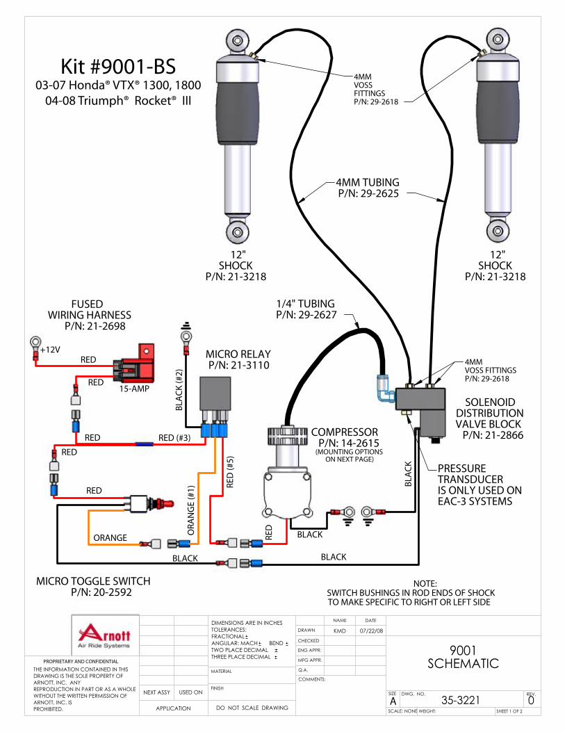
Kit #9001-BS 03-08 Honda® VTX® 1300, 1800 04-08 Triumph® Rocket® III “Engineered to Ride, Built to Last” Rev. #06 01/02/2009 Copyright © 2008, Arnott Inc. PARTS LIST PART NUMBER QUANTITY REAR AIR SUSPENSION SHOCKS 21-3218 2 VIAIR COMPRESSOR ASSEMBLY 20-2615 1 UNIVERSAL COMPRESSOR BRACKET 14-3013 1 DISTRIBUTION MANIFOLD 21-2866 1 MANIFOLD BRACKET W/ FASTENERS 14-2849 1 SPEED REDUCING MUFFLER 29-2710 1 FUSED WIRING HARNESS 21-2698 1 MICRO-TOGGLE SWITCH 20-2592 1 RELAY ASSEMBLY 21-3110 1 8mm x 1.25mm x 30mm SHCS 29-3219 4 8mm x 1.25mm x 40mm SHCS 29-3220 2 4mm VOSS® AIR FITTINGS 29-2618 5 4mm NYLON TUBING 29-2625 6-FT 1/4” NYLON TUBING 29-2627 3-FT VELCRO® 29-3020 6” HARNESS CABLE TIES 29-2617 8 SPLIT LOOM 29-3000 3-FT TM
Transcript of “Engineered to Ride, Built to Last” - arnottinfo.comarnottinfo.com/manuals/KIT-9001-BS.pdf ·...

Kit #9001-BS03-08 Honda® VTX® 1300, 1800
04-08 Triumph® Rocket® III
“Engineered to Ride, Built to Last”
Rev. #06 01/02/2009Copyright © 2008, Arnott Inc.
PARTS LIST PART NUMBER QUANTITY
REAR AIR SUSPENSION SHOCKS 21-3218 2VIAIR COMPRESSOR ASSEMBLY 20-2615 1UNIVERSAL COMPRESSOR BRACKET 14-3013 1DISTRIBUTION MANIFOLD 21-2866 1MANIFOLD BRACKET W/ FASTENERS 14-2849 1SPEED REDUCING MUFFLER 29-2710 1FUSED WIRING HARNESS 21-2698 1MICRO-TOGGLE SWITCH 20-2592 1RELAY ASSEMBLY 21-3110 18mm x 1.25mm x 30mm SHCS 29-3219 48mm x 1.25mm x 40mm SHCS 29-3220 24mm VOSS® AIR FITTINGS 29-2618 54mm NYLON TUBING 29-2625 6-FT1/4” NYLON TUBING 29-2627 3-FTVELCRO® 29-3020 6”HARNESS CABLE TIES 29-2617 8SPLIT LOOM 29-3000 3-FT
TM
BLACK
1/4" TUBINGP/N: 29-2627
(MOUNTING OPTIONSON NEXT PAGE)
15-AMP
RED
RED
RED
COMPRESSORP/N: 14-2615
BLACK
BLA
CK PRESSURE TRANSDUCERIS ONLY USED ONEAC-3 SYSTEMS
RED (#3)
ORA
NG
E (#
1) RED
(#5)
BLA
CK (#
2)
MICRO RELAYP/N: 21-3110
RED
RED
4MM TUBINGP/N: 29-2625
+12V
SOLENOID DISTRIBUTIONVALVE BLOCK
P/N: 21-2866
4MM VOSS FITTINGSP/N: 29-2618
4MMVOSSFITTINGSP/N: 29-2618
FUSEDWIRING HARNESS
P/N: 21-2698
12"SHOCK
P/N: 21-3218
NOTE:SWITCH BUSHINGS IN ROD ENDS OF SHOCKTO MAKE SPECIFIC TO RIGHT OR LEFT SIDE
MICRO TOGGLE SWITCHP/N: 20-2592
RED
BLACK
ORANGE
12"SHOCK
P/N: 21-3218
WEIGHT:
035-3221
KMD 07/22/08
9001
SCHEMATICPROPRIETARY AND CONFIDENTIAL
THE INFORMATION CONTAINED IN THISDRAWING IS THE SOLE PROPERTY OFARNOTT, INC. ANY REPRODUCTION IN PART OR AS A WHOLEWITHOUT THE WRITTEN PERMISSION OFARNOTT, INC. IS PROHIBITED.
COMMENTS:
SHEET 1 OF 2
Q.A.
MFG APPR.
ENG APPR.
CHECKED
DRAWN
DATENAMEDIMENSIONS ARE IN INCHESTOLERANCES:FRACTIONALANGULAR: MACH BEND TWO PLACE DECIMAL THREE PLACE DECIMAL
NEXT ASSY USED ON
APPLICATION DO NOT SCALE DRAWING
FINISH
MATERIAL
REV.
ADWG. NO.SIZE
SCALE: NONE
Kit #9001-BS03-07 Honda® VTX® 1300, 1800
04-08 Triumph® Rocket® III

OPTION #1
OPTION #2
OPTION #3
COMPRESSORP/N: 14-2615
BRACKET14-3013
COMPRESSOR MOUNTING OPTIONS
BRACKET ON RIGHT SIDE
BRACKET ON LEFT SIDE
NO BRACKET, USE SUPPLIEDVELCRO FOR MOUNTING
WEIGHT:
035-3221
KMD 07/22/08
9001SCHEMATICPROPRIETARY AND CONFIDENTIAL
THE INFORMATION CONTAINED IN THISDRAWING IS THE SOLE PROPERTY OFARNOTT, INC. ANY REPRODUCTION IN PART OR AS A WHOLEWITHOUT THE WRITTEN PERMISSION OFARNOTT, INC. IS PROHIBITED.
COMMENTS:
SHEET 2 OF 2
Q.A.
MFG APPR.
ENG APPR.
CHECKED
DRAWN
DATENAMEDIMENSIONS ARE IN INCHESTOLERANCES:FRACTIONALANGULAR: MACH BEND TWO PLACE DECIMAL THREE PLACE DECIMAL
NEXT ASSY USED ON
APPLICATION DO NOT SCALE DRAWING
FINISH
MATERIAL
REV.
ADWG. NO.SIZE
SCALE: NONE

THANK YOU!
Thank you for purchasing the Arnott Cycle Air System! This system provides you with the ability to maintain your bike at a constant level regardless of load, resulting in enhanced vehicle ride, handling, and performance.
Proper installation is essential to experience and appreciate the bene�ts of this system. Please take a moment to review these installation instructions before you begin to install this system on your bike. Reviewing the components and the parts list below will familiarize you with the system.
It is equally important to be aware of and take all necessary safety measures while installing your new Air Ride System. This includes proper lifting and immobilizing of the bike, and isolation of any stored energy to prevent personal injury or property damage.
SAFETY WARNING:
Do not in�ate the air spring assembly unless it is supported on both ends by the vehicle frame and suspension system, or by another adequate means. Doing so may result in serious injury and damage to the air spring assembly and surrounding environment.
The maximum recommended in�ation pressure of the air spring is 100 psi. Over-in�ation of the air spring, as well as improper use or installation of the assembly, may result in serious injury and damage to the air spring assembly and the surrounding environment.
Take precautions not to exceed the Gross Vehicle Weight Rating (GVWR, or the maximum load) recommended by the manufacturer. The air springs are rated for a maximum pressure of 100 psi. This pressure may, however, allow too great a load to be carried on most vehicles. For best results, load the vehicle and have it weighed, then compare the vehicle weight with the maximum allowed. Consult your recommended load. It is important that all vehicle’s Owner Manual recommendations are followed for your own safety and to prevent damage to the vehicle. Air Springs DO NOT increase the GVWR set by the manufacturer.
NEVER MAKE ADJUSTMENTS TO THE AIR RIDE SYSTEM WHILE THE VEHICLE IS IN MOTION. ADJUSTING THE AIR
SUSPENSION WHILE VEHICLE IS IN MOTION CAN AFFECT THE STABILITY AND HANDLING, WHICH COULD RESULT
IN DEATH OR SERIOUS INJURY. WARNING
[1]

[2]
(A.) PREPARING THE BIKE:
1. After removing the seat, disconnect the battery, negative (-) cable �rst.
2. Loosen and remove the upper shock mounting hardware.
3. Loosen and remove the lower shock mounting hardware.
(B.) REMOVING THE FACTORY SHOCKS:
Use a solid, level surface to position the bike on a motorcycle lift and use all recommended safety techniques. Lift the bike so the rear wheel is just slightly o� the ground. Always refer to the Owner’s Manual for the bike and instructions for the motorcycle lift for all correct lifting proceedures. It is also recommended that you protect any chrome or painted surfaces that may be damaged during lifting or installation process.
REMOVE THE MOTORCYCLE SEAT BEFORE STARTING THE INSTALLATION.
4. Carefully remove factory shock absorbers from the rear suspension.

[3]
2. Supplied with the kit are 6 new mounting bolts, the 2-longer bolts are to be used on the top mount of the VTX® . The 4-shorter bolts are for the lower VTX® mounts and all 4 of the Rocket® III mounts.
3. Mount the new shocks one at a time starting with the lower mount �rst, then adjust the height of the bike to align the upper mount. Tighten all shock mounting hardware to 25 ft-lbs. (34 Nm).
1. Before �nal assembly, apply 2-3 drops of Loctite® 243 (Blue), to the threads of all shock mounting hardware.
(C.) INSTALLING THE REAR AIR SHOCKS:

[4]
(D.) INSTALLING THE INFLATION SYSTEM:
1. A preferred mounting location is under the bike’s left side cover. Use the Velcro® strip supplied in the kit and attach one side to the side cover and the other to the compressor.
2. Attach the compressor to the side cover. Using the 1/4” line, connect to the compressor and route towards the battery area. The side cover also makes a good mounting point for the toggle switch.
3. Locate a suitable location to mount the manifold. Connect the ¼” line, leading from the compressor, to the valve block via the “push to connect” �tting. Supplied with the kit is a speed reducing mu�er than can be used to slow the speed of the drop. If used it is to be threaded into the open port opposite of the elbow.NOTE: Make sure air line is cut square on the end to ensure a good seal in the �tting.
The in�ation system consists of a compressor with a remote solenoid/distribution valve block. The basic system comes with a toggle switch that can be installed several places on your bike. The �nal location of the switch and compressor is ultimately up to the installer.
Split loom is provided to cover the air hose as well as protect and hide any exposed wiring.
4. Route the 4mm line from the manifold to the shocks and connect to each using the 4mm VOSS® �ttings.
NOTE: VOSS �ttings seal with o-rings, do not overtighten!

[5]
5. Find a suitable location to mount the toggle switch. There are a number of locations the can be utilized to mount the toggle switch. Ultimately the location of the switch is up to the installer.
NOTE: A system schematic is included for reference.
6. The system is equipped with a relay, refer to the included schematic for a wiring diagram. Locate the fuse assembly close to the battery. Connect the ring terminaled end of the fuse harness to battery positive (+). Reconnect the battery cables, tighten to 60-96 in-lbs. (6.8-10.9 Nm).
7. Once the system is operational, use a soap and water solution to check for any leaks. Reinstall the side cover and seat, check to ensure the seat is securely locked in the frame
8. Make sure that there is adequate clearance between the rear tire and fender being sure to check both the sides and the top. Roll the bike backwards and forwards with no air in the system feeling for any friction.

[6]
Each owner or installer is unique, therefore installation of this system can be done many di�erent ways. The mounting locations of the compressor and in�ation switch are suggestions by our engineers. If proper wiring guidelines and instructions are followed, relocation of the compressor or switch will neither a�ect the system operation nor void your warranty.
Adjust air spring pressure as required for desired ride quality to maximize the bene�ts of your system. Excess pressure will result in a �rmer ride, too little pressure will allow the suspension to bottom out.
DO NOT ADJUST THE AIR RIDE SYSTEM WHILE THE BIKE IS IN MOTION, DOING SO CAN AFFECT STABILITY AND HANDLING,
THIS COULD RESULT IN DEATH OR SERIOUS INJURY. WARNING
Thank you for purchasing an Arnott Air Ride Suspension Product!
The terms Honda®, VTX 1800®,Triumph® and Rocket III® are used for reference only. Arnott Air Suspension products are in no way authorized by nor associated with the aforementioned manufacturers. All references to Honda®, VTX®, Triumph® and Rocket III® terms and models are for reference and identi�cation purposes only.
The use and installation of any Arnott Air Suspension product or kit may adversely a�ect or void your factory warranty. It is the responsibility of the motorcycle owner to check federal, state and local laws and ordinances before modifying or customizing his or her motorcycle. It is the exclusive and total responsibility of the motorcycle owner to determine the suitability of this product for his or her use. The user shall assume all legal obligations, personal injury risk and all liability duties and risk associated with the use of this product. Arnott Air Suspension products are designed and intended for the experienced o�-road motorcyclists only and intended for closed course operation.
Arnott Air Suspension products and kits are designed exclusively for OEM manufactured and equipped motorcycles with no modi�cations. Any installation of aftermarket or customized components may adversely a�ect the operation and performance of Arnott Air suspension kits and components and may void the manufacturers warranty. These directions are accurate at time of publication. Arnott Inc. reserves the right to revise speci�cations without notice.
DISCLAIMER