ENGINEERED PLASTICS - RTP Company · 2016-10-03 · 9/26/2016 1 rtpcompany.com [email protected]...
130
CUSTOM ENGINEERED THERMOPLASTICS YOUR GLOBAL COMPOUNDER OF TENNESSEE / NORTH CAROLINA 2016 ENGINEERED PLASTICS WORKSHOP Learn About Thermoplastics | Connect with Experts
Transcript of ENGINEERED PLASTICS - RTP Company · 2016-10-03 · 9/26/2016 1 rtpcompany.com [email protected]...
CUSTOM ENGINEERED THERMOPLASTICSYOUR GLOBAL COMPOUNDER OF
TENNESSEE / NORTH CAROLINA2016
ENGINEERED PLASTICS WORKSHOPLearn About Thermoplastics | Connect with Experts
RTP CompanyEngineered Plastics Workshop
PDF copies of the presentations from today’s workshop can be downloaded from our website at www.rtpcompany.com/workshoppresentations
3
Introduction to RTP Company: Your Global Compounder of Custom Engineered Thermoplastics
Kevin Jennings | Regional Sales [email protected](864) 723-9162
8:45 a.m.
7
9/26/2016
1
rtpcompany.com [email protected]
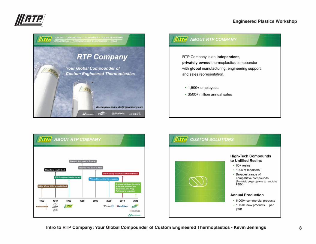
RTP CompanyYour Global Compounder of Custom Engineered Thermoplastics
RTP Company is an independent,privately owned thermoplastics compounder with global manufacturing, engineering support, and sales representation.
• 1,500+ employees
• $500+ million annual sales
ABOUT RTP COMPANY
ABOUT RTP COMPANY
High-Tech Compounds to Unfilled Resins
• 60+ resins• 100s of modifiers• Broadest range of
competitive compounds (From talc polypropylene to nanotube PEEK)
Annual Production• 6,000+ commercial products• 1,750+ new products per
year
CUSTOM SOLUTIONS
8Intro to RTP Company: Your Global Compounder of Custom Engineered Thermoplastics - Kevin Jennings
Engineered Plastics Workshop
9/26/2016
2
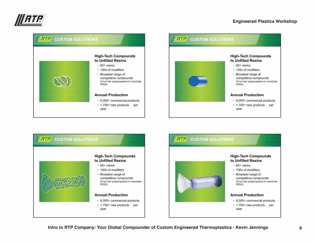
High-Tech Compounds to Unfilled Resins
• 60+ resins• 100s of modifiers• Broadest range of
competitive compounds (From talc polypropylene to nanotube PEEK)
Annual Production• 6,000+ commercial products• 1,750+ new products per
year
CUSTOM SOLUTIONS
High-Tech Compounds to Unfilled Resins
• 60+ resins• 100s of modifiers• Broadest range of
competitive compounds (From talc polypropylene to nanotube PEEK)
Annual Production• 6,000+ commercial products• 1,750+ new products per
year
CUSTOM SOLUTIONS
High-Tech Compounds to Unfilled Resins
• 60+ resins• 100s of modifiers• Broadest range of
competitive compounds (From talc polypropylene to nanotube PEEK)
Annual Production• 6,000+ commercial products• 1,750+ new products per
year
CUSTOM SOLUTIONS
High-Tech Compounds to Unfilled Resins
• 60+ resins• 100s of modifiers• Broadest range of
competitive compounds (From talc polypropylene to nanotube PEEK)
Annual Production• 6,000+ commercial products• 1,750+ new products per
year
CUSTOM SOLUTIONS
9Intro to RTP Company: Your Global Compounder of Custom Engineered Thermoplastics - Kevin Jennings
Engineered Plastics Workshop
9/26/2016
3
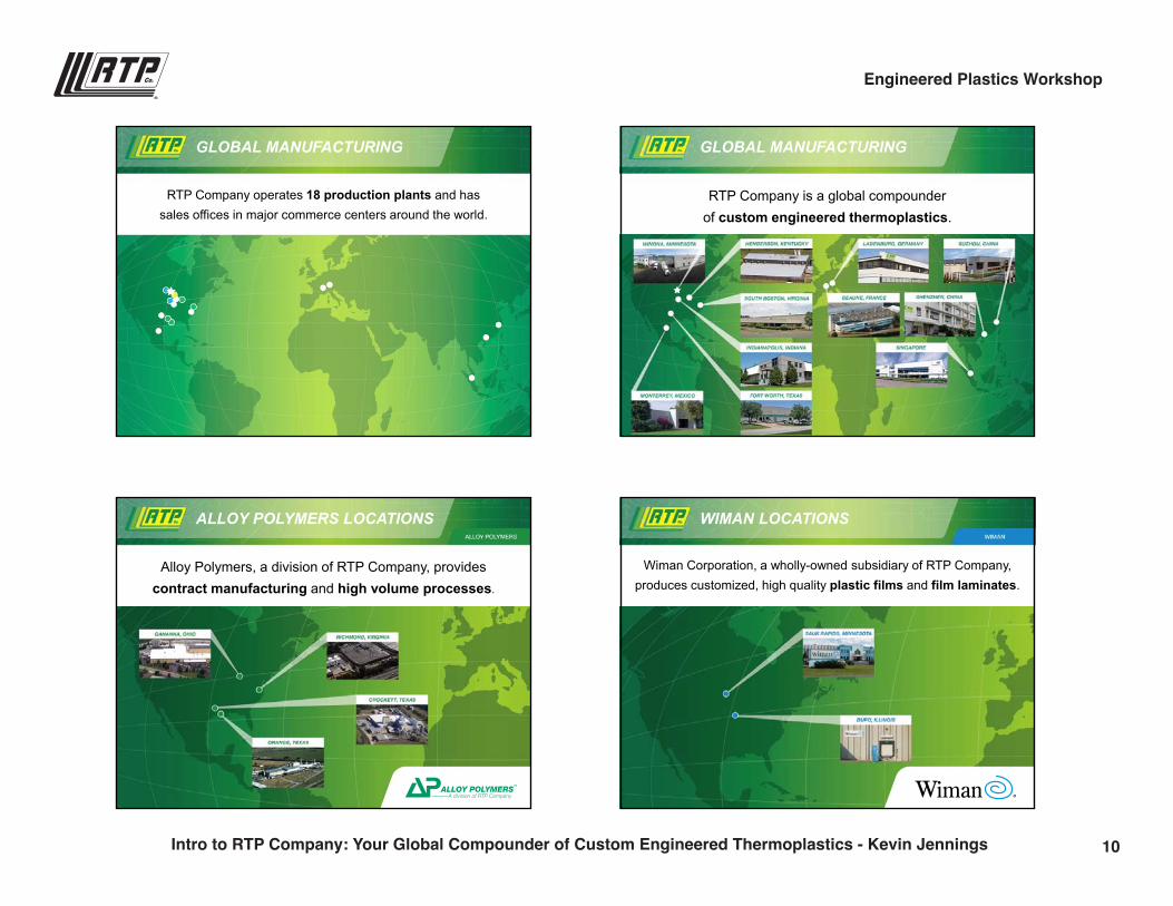
GLOBAL MANUFACTURING
RTP Company operates 18 production plants and has sales offices in major commerce centers around the world.
GLOBAL MANUFACTURING
RTP Company is a global compounder of custom engineered thermoplastics.
ALLOY POLYMERS LOCATIONS
Alloy Polymers, a division of RTP Company, provides contract manufacturing and high volume processes.
WIMAN LOCATIONS
Wiman Corporation, a wholly-owned subsidiary of RTP Company, produces customized, high quality plastic films and film laminates.
10Intro to RTP Company: Your Global Compounder of Custom Engineered Thermoplastics - Kevin Jennings
Engineered Plastics Workshop
9/26/2016
4
ESPTM LOCATIONS
Engineered Sheet Products™ (ESP™), a division of RTP Company, manufactures specialty engineered sheet.
RESMART LOCATION
RTP Company partners with ResMart, a distributor ofoff-the-shelf, unfilled resins.
Our goal is to satisfy our customers with solutions, providing…
• Technology
• Flexibility
• Speed
OUR GOAL FLEXIBLE VOLUMES
RTP Company offers the most competitive lead times in the industry.
Bags to Bulk
11Intro to RTP Company: Your Global Compounder of Custom Engineered Thermoplastics - Kevin Jennings
Engineered Plastics Workshop
9/26/2016
5
Our culture can be described as…
• A close-knit organization
• Generational/long term thinkers
• Entrepreneurial
• High spirited with a sense of urgency
• “Bureaucracy-less”
OUR CULTURE WE ARE INDEPENDENT
Our independence allows us to be objective in…
• Raw materials
• Formulations
• Solutions
GLOBAL SUPPORT
RTP Company has 100+ sales & support employees worldwide:
Americas – Canada, United States, Mexico, BrazilAsia/Pacific Rim – China, Korea, Singapore, Japan, Taiwan, IndiaEurope – Austria, Netherlands, France, Germany, United Kingdom
PRODUCT DEVELOPMENT / R&D
RTP Company has 50+ development engineers worldwide, including regional engineers for local support.
At RTP Company, our development engineers:
• Apply the most current research
• Aggressively seek new resins and additives
• Have a passion for creating the best solution for you
12Intro to RTP Company: Your Global Compounder of Custom Engineered Thermoplastics - Kevin Jennings
Engineered Plastics Workshop
9/26/2016
6
PRODUCT DEVELOPMENT / R&D
Our development servicesare available in each region of the world, and include:
• Application development• Product development• Process development• CAE support• Pilot Plant production
TECHNICAL SERVICE
RTP Company has 20+ Technical Service Engineers and Specialists worldwide, that provide:
• Plastic processing trials Injection, extrusion, compression, film, and blow molding trials
• Process optimization• Problem resolution• Customer trials and samples
• Regionally located, experienced representatives for real-time service
• Deliver personalized attention to each order
• Dedicated to your account, serving as an extension of your team
RTP Company has 30+ Customer Service Representatives worldwide, who are dedicated to serving you.
CUSTOMER SERVICE
Each year, RTP Company measures how satisfied customers are with the accessibility and helpfulness of their RTP Company Customer Service Representative. In 2015, 96% of respondents indicated that they were satisfied with the service they received.
GLOBAL COMPOUNDING
We develop it anywhere…
make it anywhere…
and support it everywhere!
• Scalability: Develop your solution on a small scale and produce your solution in large quantities
• Plant-to-plant consistency• ISO: 9001:2008 registered facilities
13Intro to RTP Company: Your Global Compounder of Custom Engineered Thermoplastics - Kevin Jennings
Engineered Plastics Workshop
9/26/2016
7
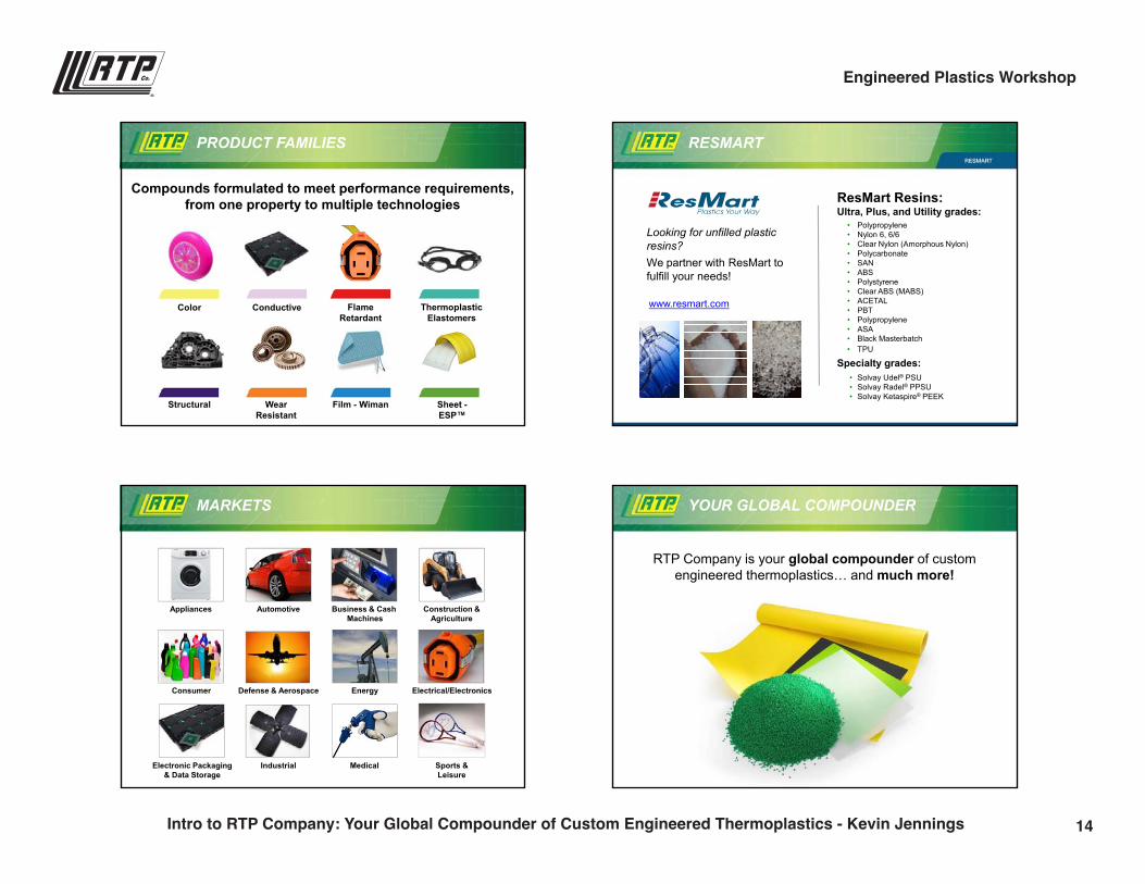
PRODUCT FAMILIES
Compounds formulated to meet performance requirements,from one property to multiple technologies
Color Conductive Flame Retardant
Thermoplastic Elastomers
Structural Wear Resistant
Film - Wiman Sheet -ESP™
RESMART
Looking for unfilled plastic resins?We partner with ResMart to fulfill your needs!
ResMart Resins:Ultra, Plus, and Utility grades:
• Polypropylene• Nylon 6, 6/6• Clear Nylon (Amorphous Nylon)• Polycarbonate• SAN• ABS• Polystyrene• Clear ABS (MABS)• ACETAL• PBT• Polypropylene• ASA • Black Masterbatch• TPU
Specialty grades:• Solvay Udel® PSU• Solvay Radel® PPSU• Solvay Ketaspire® PEEK
www.resmart.com
Automotive
Defense & Aerospace Electrical/Electronics
Industrial
Consumer Energy
Medical
Business & Cash Machines
Construction &Agriculture
Appliances
Sports & Leisure
Electronic Packaging& Data Storage
MARKETS YOUR GLOBAL COMPOUNDER
RTP Company is your global compounder of custom engineered thermoplastics… and much more!
14Intro to RTP Company: Your Global Compounder of Custom Engineered Thermoplastics - Kevin Jennings
Engineered Plastics Workshop
9/26/2016
8
rtpcompany.com [email protected]
Thank You!
15Intro to RTP Company: Your Global Compounder of Custom Engineered Thermoplastics - Kevin Jennings
Engineered Plastics Workshop
An Engineer’s Guide to Specifying the Right Thermoplastics
Steve Maki | VP of [email protected](507) 474-5371
9:00 a.m.
17
9/28/2016
1
rtpcompany.com [email protected]
An Engineer’s Guide to Specify the Right Thermoplastic
Steve MakiVice President [email protected]
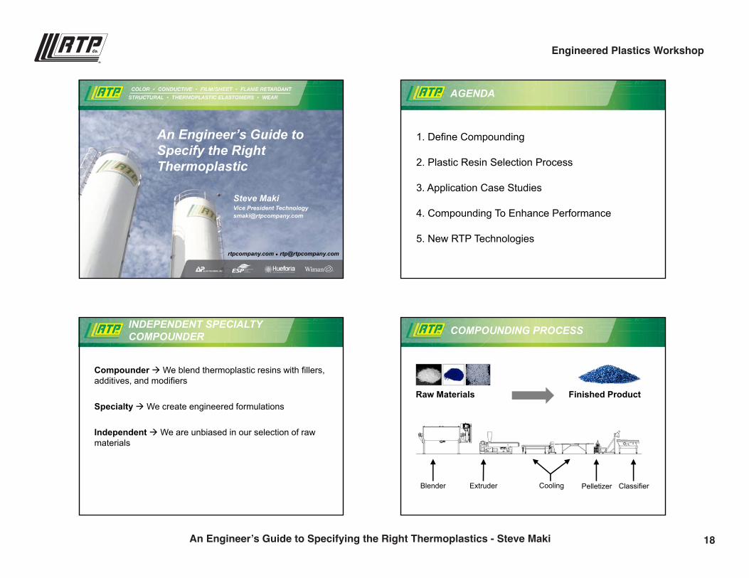
AGENDA
1. Define Compounding
2. Plastic Resin Selection Process
3. Application Case Studies
4. Compounding To Enhance Performance
5. New RTP Technologies
INDEPENDENT SPECIALTY COMPOUNDER
CompounderWe blend thermoplastic resins with fillers, additives, and modifiers
SpecialtyWe create engineered formulations
IndependentWe are unbiased in our selection of raw materials
COMPOUNDING PROCESS
Raw Materials Finished Product
Blender Extruder Pelletizer ClassifierCooling
18An Engineer’s Guide to Specifying the Right Thermoplastics - Steve Maki
Engineered Plastics Workshop
9/28/2016
2
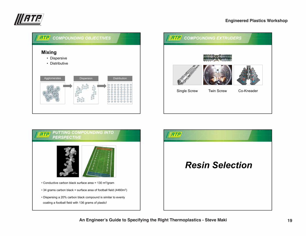
COMPOUNDING OBJECTIVES
Mixing• Dispersive• Distributive
Agglomerates Dispersion Distribution
COMPOUNDING EXTRUDERS
Single Screw Twin Screw Co-Kneader
• Conductive carbon black surface area = 130 m2/gram
• 34 grams carbon black = surface area of football field (4460m2)
• Dispersing a 20% carbon black compound is similar to evenly
coating a football field with 136 grams of plastic!
PUTTING COMPOUNDING INTO PERSPECTIVE
Resin Selection
19An Engineer’s Guide to Specifying the Right Thermoplastics - Steve Maki
Engineered Plastics Workshop
9/28/2016
3
THE DILEMMA
Which ONE Do I Choose For My Application???
60 thermoplastic resins + 100 additives = 1000’s of potential compounds Step 1: Use Resin Morphology
Step 2: Use Thermal & Cost Requirements
Step 3: Fine Tune & Special Features
PLASTIC SELECTION PROCESS
Amorphous Semi-Crystalline
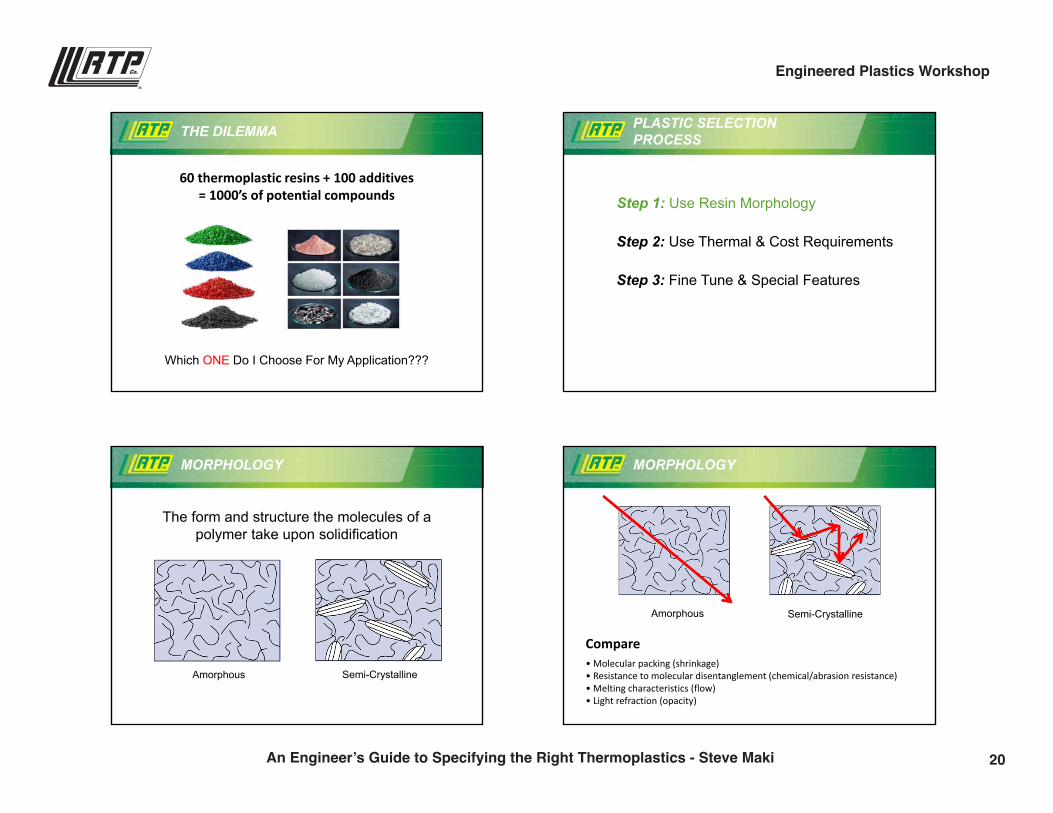
The form and structure the molecules of a polymer take upon solidification
MORPHOLOGY
Amorphous Semi-Crystalline
Compare• Molecular packing (shrinkage)• Resistance to molecular disentanglement (chemical/abrasion resistance)• Melting characteristics (flow)• Light refraction (opacity)
MORPHOLOGY
20An Engineer’s Guide to Specifying the Right Thermoplastics - Steve Maki
Engineered Plastics Workshop
9/28/2016
4
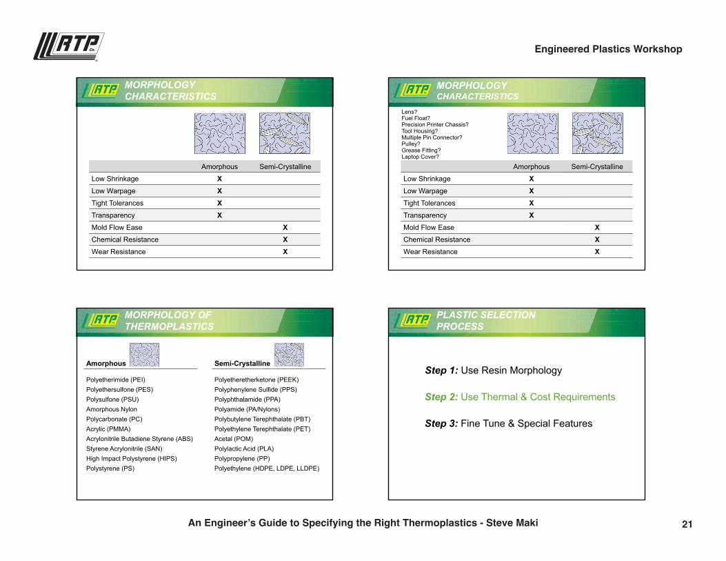
MORPHOLOGY CHARACTERISTICS
Amorphous Semi-Crystalline
Low Shrinkage XLow Warpage XTight Tolerances XTransparency XMold Flow Ease XChemical Resistance XWear Resistance X
MORPHOLOGYCHARACTERISTICS
Amorphous Semi-Crystalline
Low Shrinkage XLow Warpage XTight Tolerances XTransparency XMold Flow Ease XChemical Resistance XWear Resistance X
Lens?Fuel Float?Precision Printer Chassis?Tool Housing?Multiple Pin Connector?Pulley?Grease Fitting?Laptop Cover?
Amorphous Semi-Crystalline
Polyetherimide (PEI)Polyethersulfone (PES)Polysulfone (PSU)Amorphous NylonPolycarbonate (PC)Acrylic (PMMA)Acrylonitrile Butadiene Styrene (ABS)Styrene Acrylonitrile (SAN)High Impact Polystyrene (HIPS)Polystyrene (PS)
Polyetheretherketone (PEEK)Polyphenylene Sulfide (PPS)Polyphthalamide (PPA)Polyamide (PA/Nylons)Polybutylene Terephthalate (PBT)Polyethylene Terephthalate (PET)Acetal (POM)Polylactic Acid (PLA)Polypropylene (PP)Polyethylene (HDPE, LDPE, LLDPE)
MORPHOLOGY OF THERMOPLASTICS
Step 1: Use Resin Morphology
Step 2: Use Thermal & Cost Requirements
Step 3: Fine Tune & Special Features
PLASTIC SELECTION PROCESS
21An Engineer’s Guide to Specifying the Right Thermoplastics - Steve Maki
Engineered Plastics Workshop
9/28/2016
5
Amorphous Semi-Crystalline
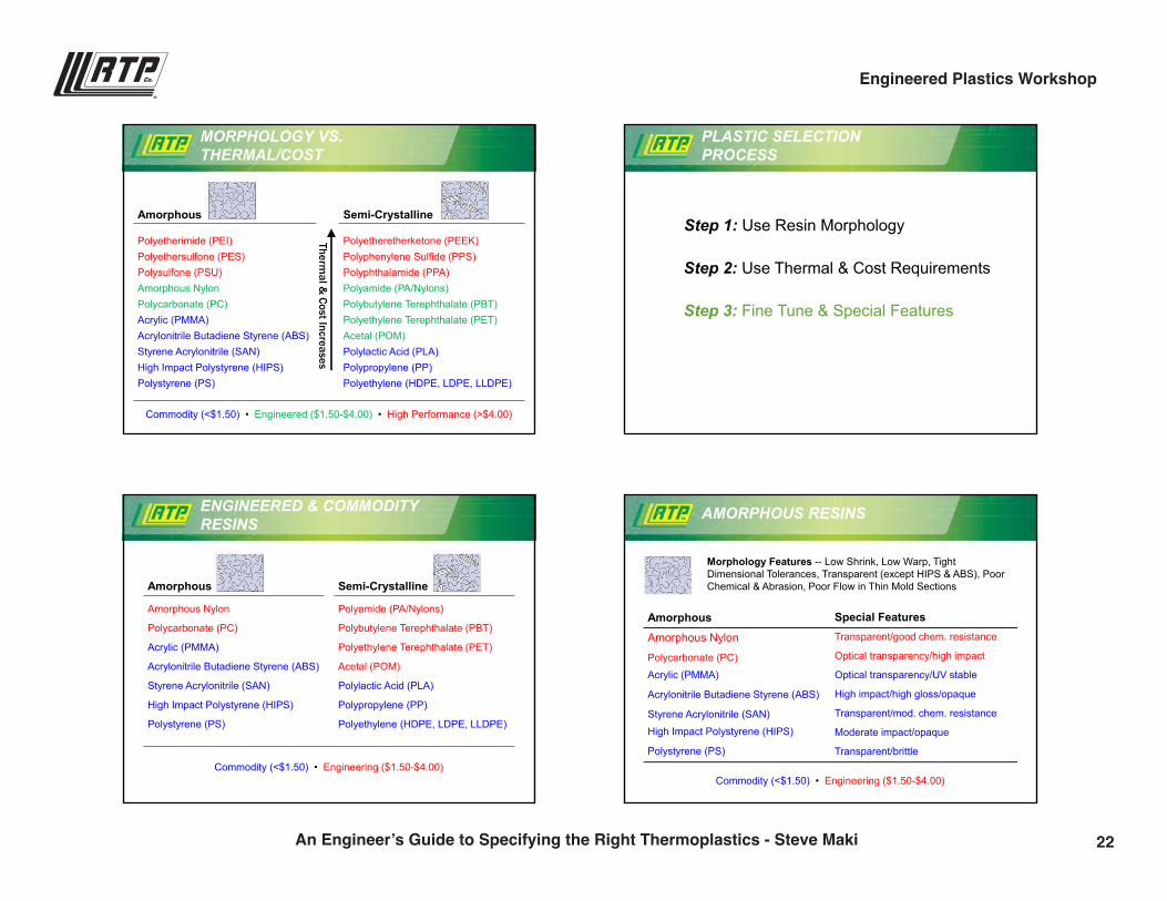
Polyetherimide (PEI)Polyethersulfone (PES)Polysulfone (PSU)Amorphous NylonPolycarbonate (PC)Acrylic (PMMA)Acrylonitrile Butadiene Styrene (ABS)Styrene Acrylonitrile (SAN)High Impact Polystyrene (HIPS)Polystyrene (PS)
Polyetheretherketone (PEEK)Polyphenylene Sulfide (PPS)Polyphthalamide (PPA)Polyamide (PA/Nylons)Polybutylene Terephthalate (PBT)Polyethylene Terephthalate (PET)Acetal (POM)Polylactic Acid (PLA)Polypropylene (PP)Polyethylene (HDPE, LDPE, LLDPE)
Thermal &
Cost Increases
Commodity (<$1.50) • Engineered ($1.50-$4.00) • High Performance (>$4.00)
MORPHOLOGY VS. THERMAL/COST
PLASTIC SELECTION PROCESS
Step 1: Use Resin Morphology
Step 2: Use Thermal & Cost Requirements
Step 3: Fine Tune & Special Features
ENGINEERED & COMMODITY RESINS
Amorphous Semi-Crystalline
Amorphous Nylon
Polycarbonate (PC)
Acrylic (PMMA)
Acrylonitrile Butadiene Styrene (ABS)
Styrene Acrylonitrile (SAN)
High Impact Polystyrene (HIPS)
Polystyrene (PS)
Polyamide (PA/Nylons)
Polybutylene Terephthalate (PBT)
Polyethylene Terephthalate (PET)
Acetal (POM)
Polylactic Acid (PLA)
Polypropylene (PP)
Polyethylene (HDPE, LDPE, LLDPE)
Commodity (<$1.50) • Engineering ($1.50-$4.00)
AMORPHOUS RESINS
Commodity (<$1.50) • Engineering ($1.50-$4.00)
Morphology Features -- Low Shrink, Low Warp, Tight Dimensional Tolerances, Transparent (except HIPS & ABS), Poor Chemical & Abrasion, Poor Flow in Thin Mold Sections
AmorphousAmorphous Nylon
Polycarbonate (PC)
Acrylic (PMMA)
Acrylonitrile Butadiene Styrene (ABS)
Styrene Acrylonitrile (SAN)
High Impact Polystyrene (HIPS)
Polystyrene (PS)
Special FeaturesTransparent/good chem. resistance
Optical transparency/high impact
Optical transparency/UV stable
High impact/high gloss/opaque
Transparent/mod. chem. resistance
Moderate impact/opaque
Transparent/brittle
22An Engineer’s Guide to Specifying the Right Thermoplastics - Steve Maki
Engineered Plastics Workshop
9/28/2016
6
SEMI-CRYSTALLINE RESIN
Morphology Features -- Excellent Chemical Resistance, Excellent Abrasion Resistance, Good Flow in Thin Mold Sections, Poor Dimensions, Opaque
Commodity (<$1.50) • Engineering ($1.50-$4.00)
Semi-CrystallineNylon 6/12Nylon 6/6
Nylon 6Polybutylene Terephthalate (PBT)
Polyethylene Terephthalate (PET)Acetal (POM)
Polylactic Acid (PLA)
Polypropylene (PP)Polyethylene (HDPE, LDPE, LLDPE)
Special FeaturesLess Sensitive to humidity vs. 6&6/6Better thermal vs. 6/humidity DepHides GF/strong but humidity DepGood electricals/easier to mold
Good electricals/difficult to moldLow wear & friction/high fatigue
Green/Low impact & thermal
Poor low temp impact/mod thermalGood low temp impact
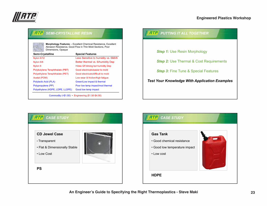
PUTTING IT ALL TOGETHER
Step 1: Use Resin Morphology
Step 2: Use Thermal & Cost Requirements
Step 3: Fine Tune & Special Features
Test Your Knowledge With Application Examples
CASE STUDY
CD Jewel Case
• Transparent
• Flat & Dimensionally Stable
• Low Cost
PS
CASE STUDY
Gas Tank
• Good chemical resistance
• Good low temperature impact
• Low cost
HDPE
23An Engineer’s Guide to Specifying the Right Thermoplastics - Steve Maki
Engineered Plastics Workshop
9/28/2016
7
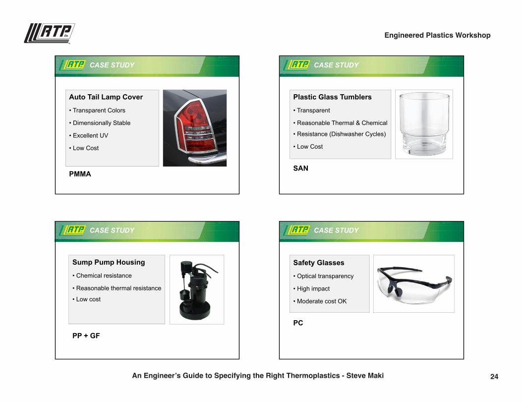
CASE STUDY
Auto Tail Lamp Cover
• Transparent Colors
• Dimensionally Stable
• Excellent UV
• Low Cost
PMMA
CASE STUDY
Plastic Glass Tumblers
• Transparent
• Reasonable Thermal & Chemical
• Resistance (Dishwasher Cycles)
• Low Cost
SAN
CASE STUDY
Sump Pump Housing
• Chemical resistance
• Reasonable thermal resistance
• Low cost
PP + GF
CASE STUDY
Safety Glasses
• Optical transparency
• High impact
• Moderate cost OK
PC
9/28/2016
7
CASE STUDY
Auto Tail Lamp Cover
• Transparent Colors
• Dimensionally Stable
• Excellent UV
• Low Cost
PMMA
CASE STUDY
Plastic Glass Tumblers
• Transparent
• Reasonable Thermal & Chemical
• Resistance (Dishwasher Cycles)
• Low Cost
SAN
CASE STUDY
Sump Pump Housing
• Chemical resistance
• Reasonable thermal resistance
• Low cost
PP + GF
CASE STUDY
Safety Glasses
• Optical transparency
• High impact
• Moderate cost OK
PC
24An Engineer’s Guide to Specifying the Right Thermoplastics - Steve Maki
Engineered Plastics Workshop
9/28/2016
8
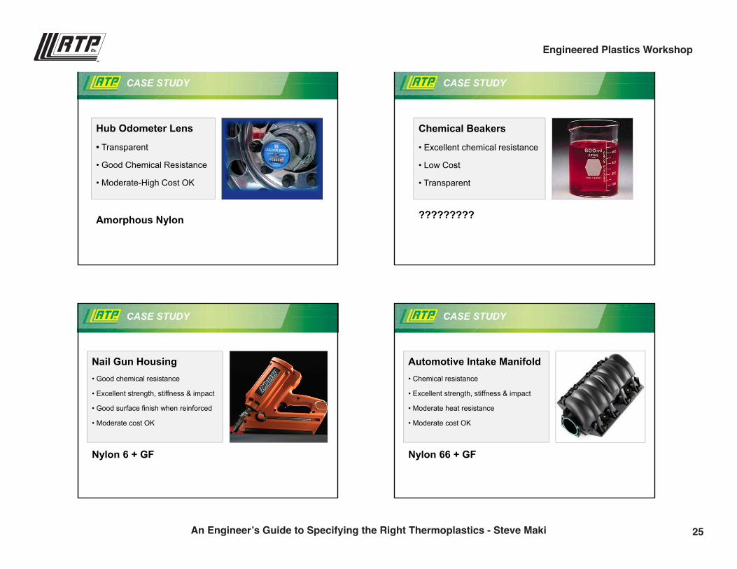
CASE STUDY
Hub Odometer Lens
• Transparent
• Good Chemical Resistance
• Moderate-High Cost OK
Amorphous Nylon
CASE STUDY
Chemical Beakers
• Excellent chemical resistance
• Low Cost
• Transparent
?????????
CASE STUDY
Nail Gun Housing• Good chemical resistance
• Excellent strength, stiffness & impact
• Good surface finish when reinforced
• Moderate cost OK
Nylon 6 + GF
CASE STUDY
Automotive Intake Manifold• Chemical resistance
• Excellent strength, stiffness & impact
• Moderate heat resistance
• Moderate cost OK
Nylon 66 + GF
25An Engineer’s Guide to Specifying the Right Thermoplastics - Steve Maki
Engineered Plastics Workshop
9/28/2016
9
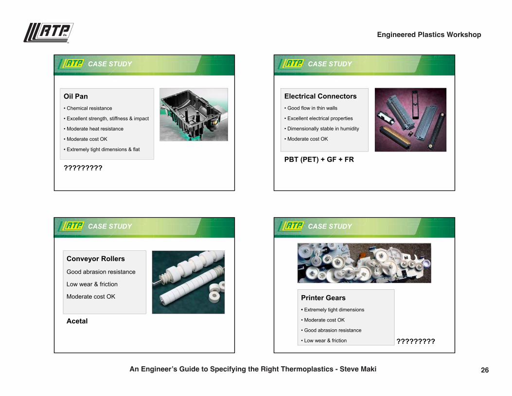
CASE STUDY
Oil Pan• Chemical resistance
• Excellent strength, stiffness & impact
• Moderate heat resistance
• Moderate cost OK
• Extremely tight dimensions & flat
?????????
CASE STUDY
Electrical Connectors• Good flow in thin walls
• Excellent electrical properties
• Dimensionally stable in humidity
• Moderate cost OK
PBT (PET) + GF + FR
CASE STUDY
Conveyor Rollers
Good abrasion resistance
Low wear & friction
Moderate cost OK
Acetal
CASE STUDY
Printer Gears• Extremely tight dimensions
• Moderate cost OK
• Good abrasion resistance
• Low wear & friction ?????????
26An Engineer’s Guide to Specifying the Right Thermoplastics - Steve Maki
Engineered Plastics Workshop
9/28/2016
10
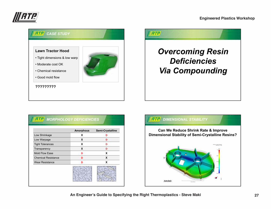
CASE STUDY
Lawn Tractor Hood
• Tight dimensions & low warp
• Moderate cost OK
• Chemical resistance
• Good mold flow
?????????
Overcoming Resin Deficiencies
Via Compounding
MORPHOLOGY DEFICIENCIES
Amorphous Semi-CrystallineLow Shrinkage X D
Low Warpage X D
Tight Tolerances X D
Transparency X D
Mold Flow Ease D XChemical Resistance D XWear Resistance D X
DIMENSIONAL STABILITY
Can We Reduce Shrink Rate & Improve Dimensional Stability of Semi-Crystalline Resins?
27An Engineer’s Guide to Specifying the Right Thermoplastics - Steve Maki
Engineered Plastics Workshop
9/28/2016
11
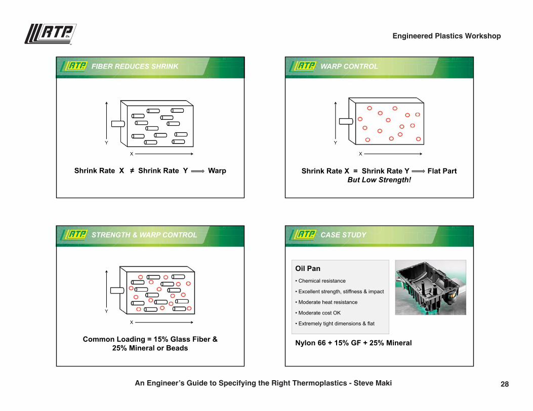
FIBER REDUCES SHRINK
Shrink Rate X ≠ Shrink Rate Y Warp
X
Y
Shrink Rate X = Shrink Rate Y Flat PartBut Low Strength!
WARP CONTROL
X
Y
STRENGTH & WARP CONTROL
Common Loading = 15% Glass Fiber &25% Mineral or Beads
X
Y
CASE STUDY
Oil Pan• Chemical resistance
• Excellent strength, stiffness & impact
• Moderate heat resistance
• Moderate cost OK
• Extremely tight dimensions & flat
Nylon 66 + 15% GF + 25% Mineral
28An Engineer’s Guide to Specifying the Right Thermoplastics - Steve Maki
Engineered Plastics Workshop
9/28/2016
12
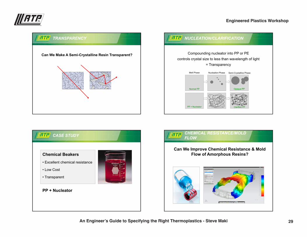
TRANSPARENCY
Can We Make A Semi-Crystalline Resin Transparent?
NUCLEATION/CLARIFICATION
Compounding nucleator into PP or PE controls crystal size to less than wavelength of light
= Transparency
Melt Phase Nucleation Phase Semi-Crystalline Phase
Normal PP
PP + Nucleator Clarified PP
Opaque PP
CASE STUDY
Chemical Beakers
• Excellent chemical resistance
• Low Cost
• Transparent
PP + Nucleator
CHEMICAL RESISTANCE/MOLD FLOW
Can We Improve Chemical Resistance & Mold Flow of Amorphous Resins?
29An Engineer’s Guide to Specifying the Right Thermoplastics - Steve Maki
Engineered Plastics Workshop
9/28/2016
13
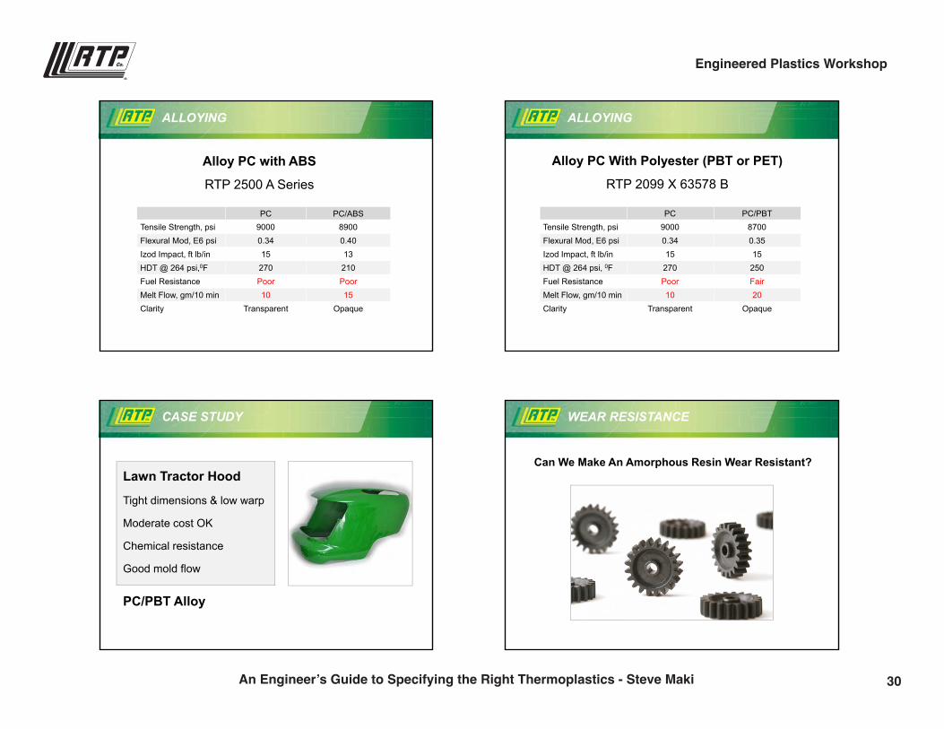
ALLOYING
Alloy PC with ABS
RTP 2500 A Series
PC PC/ABSTensile Strength, psi 9000 8900Flexural Mod, E6 psi 0.34 0.40Izod Impact, ft lb/in 15 13HDT @ 264 psi,0F 270 210Fuel Resistance Poor PoorMelt Flow, gm/10 min 10 15Clarity Transparent Opaque
ALLOYING
Alloy PC With Polyester (PBT or PET)
RTP 2099 X 63578 B
PC PC/PBTTensile Strength, psi 9000 8700Flexural Mod, E6 psi 0.34 0.35Izod Impact, ft lb/in 15 15HDT @ 264 psi, 0F 270 250Fuel Resistance Poor FairMelt Flow, gm/10 min 10 20Clarity Transparent Opaque
CASE STUDY
Lawn Tractor Hood
Tight dimensions & low warp
Moderate cost OK
Chemical resistance
Good mold flow
PC/PBT Alloy
WEAR RESISTANCE
Can We Make An Amorphous Resin Wear Resistant?
30An Engineer’s Guide to Specifying the Right Thermoplastics - Steve Maki
Engineered Plastics Workshop
9/28/2016
14
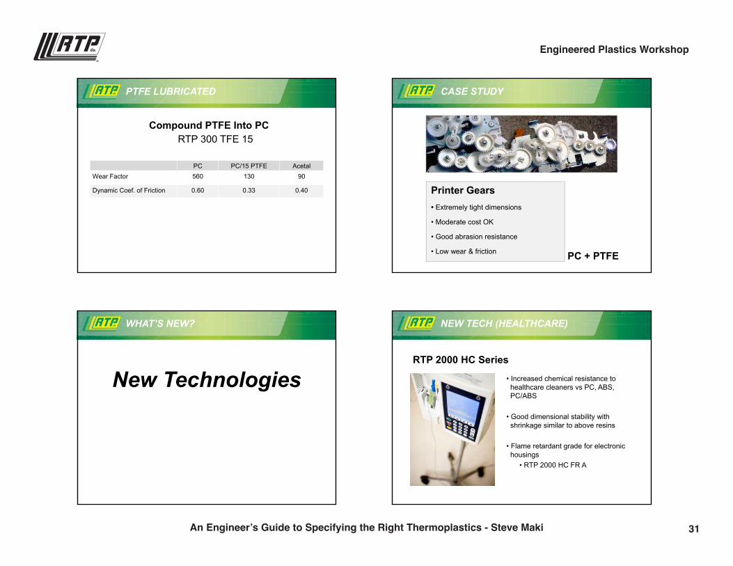
PTFE LUBRICATED
Compound PTFE Into PCRTP 300 TFE 15
PC PC/15 PTFE AcetalWear Factor 560 130 90
Dynamic Coef. of Friction 0.60 0.33 0.40
CASE STUDY
Printer Gears• Extremely tight dimensions
• Moderate cost OK
• Good abrasion resistance
• Low wear & friction PC + PTFE
WHAT’S NEW?
New Technologies
NEW TECH (HEALTHCARE)
RTP 2000 HC Series
• Increased chemical resistance to healthcare cleaners vs PC, ABS, PC/ABS
• Good dimensional stability with shrinkage similar to above resins
• Flame retardant grade for electronic housings
• RTP 2000 HC FR A
31An Engineer’s Guide to Specifying the Right Thermoplastics - Steve Maki
Engineered Plastics Workshop
9/28/2016
15
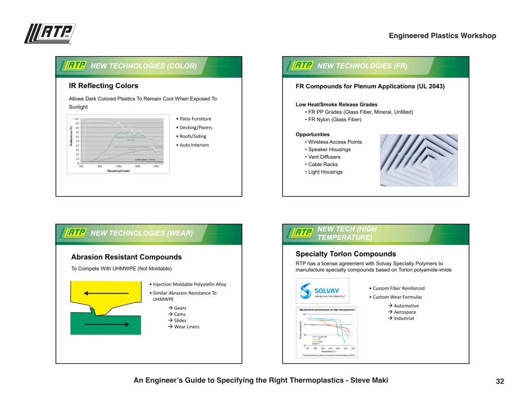
NEW TECHNOLOGIES (COLOR)
IR Reflecting ColorsAllows Dark Colored Plastics To Remain Cool When Exposed To Sunlight
• Patio Furniture
• Decking/Pavers
• Roofs/Siding
• Auto Interiors
NEW TECHNOLOGIES (FR)
FR Compounds for Plenum Applications (UL 2043)
Low Heat/Smoke Release Grades• FR PP Grades (Glass Fiber, Mineral, Unfilled)• FR Nylon (Glass Fiber)
Opportunities• Wireless Access Points• Speaker Housings• Vent Diffusers• Cable Racks• Light Housings
NEW TECHNOLOGIES (WEAR)
Abrasion Resistant CompoundsTo Compete With UHMWPE (Not Moldable)
• Injection Moldable Polyolefin Alloy
• Similar Abrasion Resistance ToUHMWPE
Gears Cams SlidesWear Liners
NEW TECH (HIGH TEMPERATURE)
Specialty Torlon CompoundsRTP has a license agreement with Solvay Specialty Polymers to manufacture specialty compounds based on Torlon polyamide-imide
• Custom Fiber Reinforced
• Custom Wear Formulas
Automotive Aerospace Industrial
32An Engineer’s Guide to Specifying the Right Thermoplastics - Steve Maki
Engineered Plastics Workshop
9/28/2016
16
REVIEW
Intro To CompoundingThe DilemmaResin Selection Procedure
• Resin Morphology• Resin Cost & Thermal Performance• Unique Resin Features
Application Case StudiesCompounding in Performance
• Overcoming Resin Deficiencies
Introduction To New Technologiesrtpcompany.com [email protected]
Steve MakiVice President [email protected]
Questions?
Thank you!
33An Engineer’s Guide to Specifying the Right Thermoplastics - Steve Maki
Engineered Plastics Workshop

Tough or Strong? Short or Long? Dialing in Mechanical Properties
Karl Hoppe | Senior Product Development [email protected](507) 474-5367
10:00 a.m.
35
9/28/2016
1
rtpcompany.com [email protected]
Karl HoppeSenior Product Development Engineer
Tough or Strong? Short or Long? Dialing in Mechanical Performance
STRENGTH
STIFFNESS IMPACT
36Tough or Strong? Short or Long? Dialing in Mechanical Properties - Karl Hoppe
Engineered Plastics Workshop
9/28/2016
2
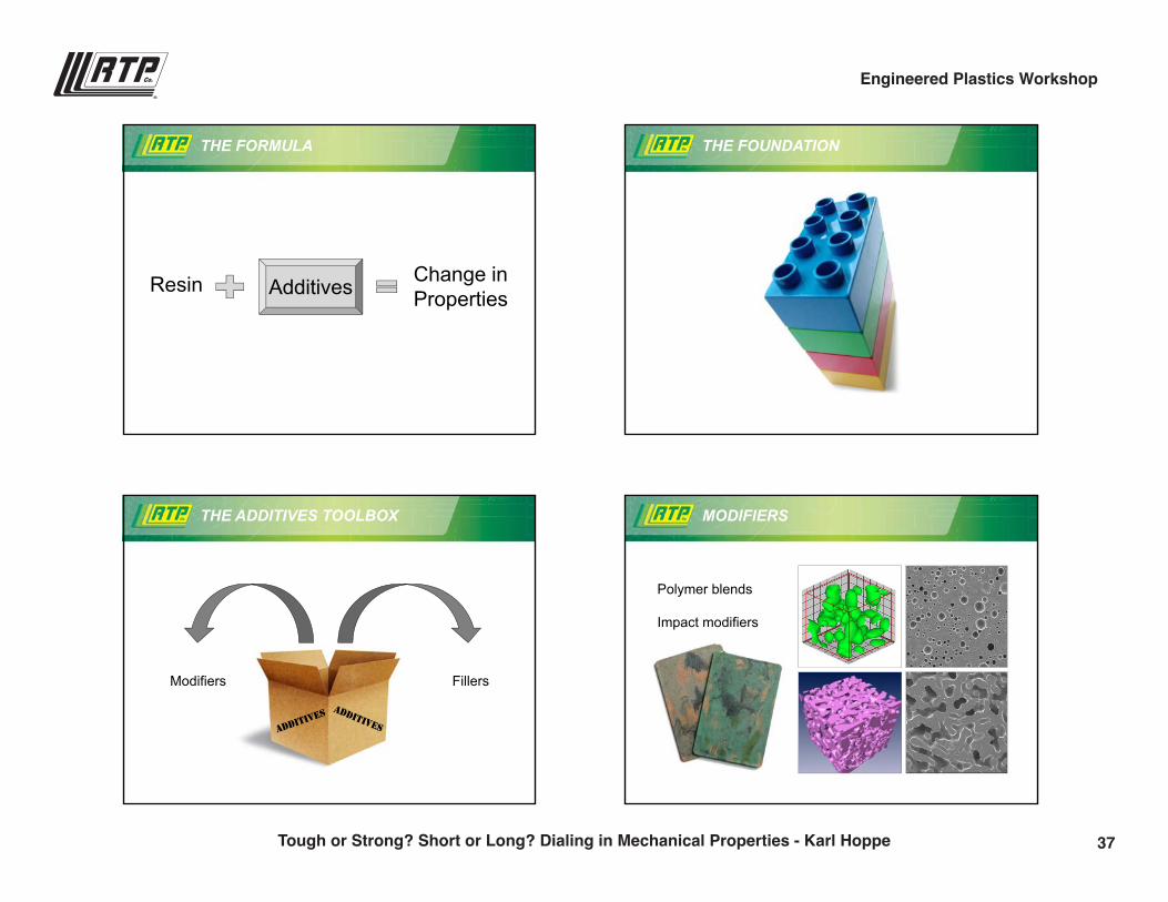
THE FORMULA
Resin Change inPropertiesAdditives
THE FOUNDATION
THE ADDITIVES TOOLBOX
Modifiers Fillers
MODIFIERS
Polymer blends
Impact modifiers
37Tough or Strong? Short or Long? Dialing in Mechanical Properties - Karl Hoppe
Engineered Plastics Workshop
9/28/2016
3
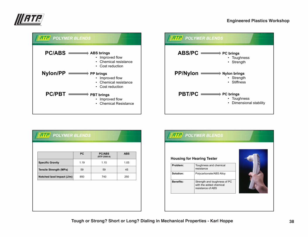
POLYMER BLENDS
PBT brings • Improved flow• Chemical Resistance
ABS brings • Improved flow• Chemical resistance• Cost reduction
PP brings • Improved flow• Chemical resistance• Cost reduction
PC/ABS
Nylon/PP
PC/PBT
PC brings• Toughness• Strength
POLYMER BLENDS
Nylon brings• Strength• Stiffness
PC brings • Toughness• Dimensional stability
ABS/PC
PP/Nylon
PBT/PC
POLYMER BLENDS
PC PC/ABS (RTP 2500 A)
ABS
Specific Gravity 1.19 1.15 1.05
Tensile Strength (MPa) 59 59 45
Notched Izod Impact (J/m) 850 740 250
POLYMER BLENDS
Housing for Hearing Tester
Problem: Toughness and chemical resistance
Solution: Polycarbonate/ABS Alloy
Benefits: Strength and toughness of PC with the added chemical resistance of ABS
38Tough or Strong? Short or Long? Dialing in Mechanical Properties - Karl Hoppe
Engineered Plastics Workshop
9/28/2016
4
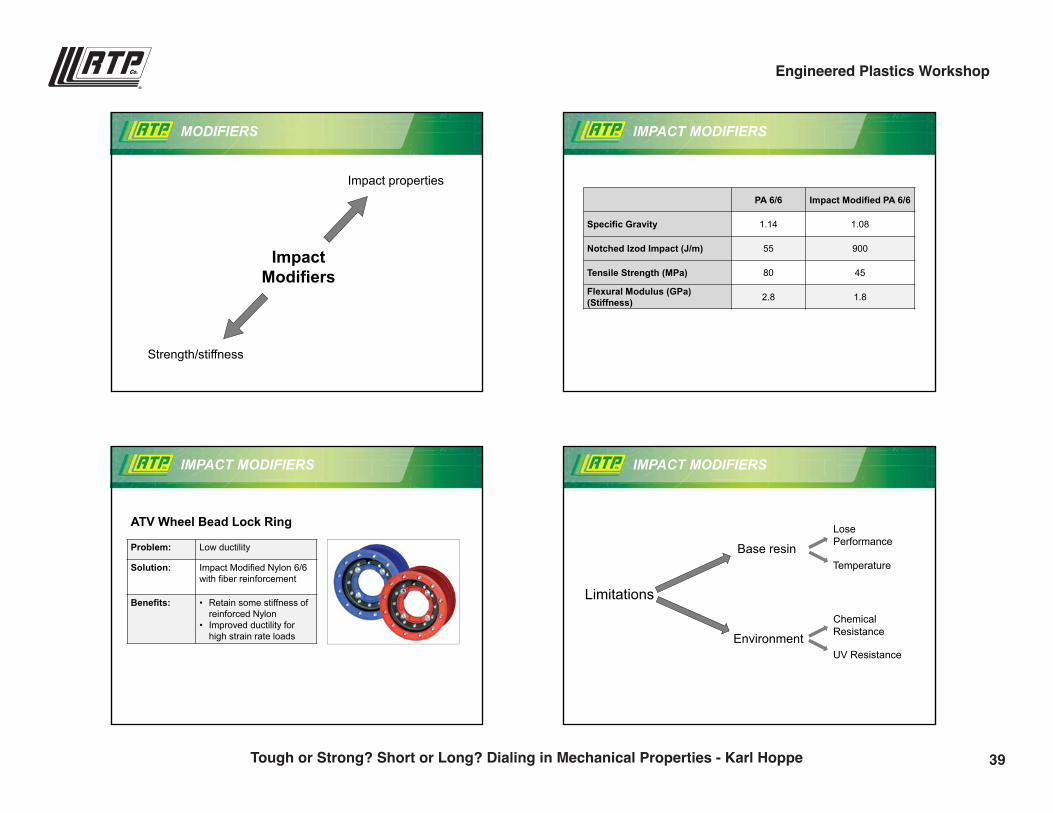
MODIFIERS
ImpactModifiers
Impact properties
Strength/stiffness
IMPACT MODIFIERS
PA 6/6 Impact Modified PA 6/6
Specific Gravity 1.14 1.08
Notched Izod Impact (J/m) 55 900
Tensile Strength (MPa) 80 45
Flexural Modulus (GPa) (Stiffness) 2.8 1.8
IMPACT MODIFIERS
ATV Wheel Bead Lock Ring
Problem: Low ductility
Solution: Impact Modified Nylon 6/6 with fiber reinforcement
Benefits: • Retain some stiffness of reinforced Nylon
• Improved ductility for high strain rate loads
IMPACT MODIFIERS
Limitations
Base resin
Environment
Lose Performance
Temperature
Chemical Resistance
UV Resistance
39Tough or Strong? Short or Long? Dialing in Mechanical Properties - Karl Hoppe
Engineered Plastics Workshop
9/28/2016
5
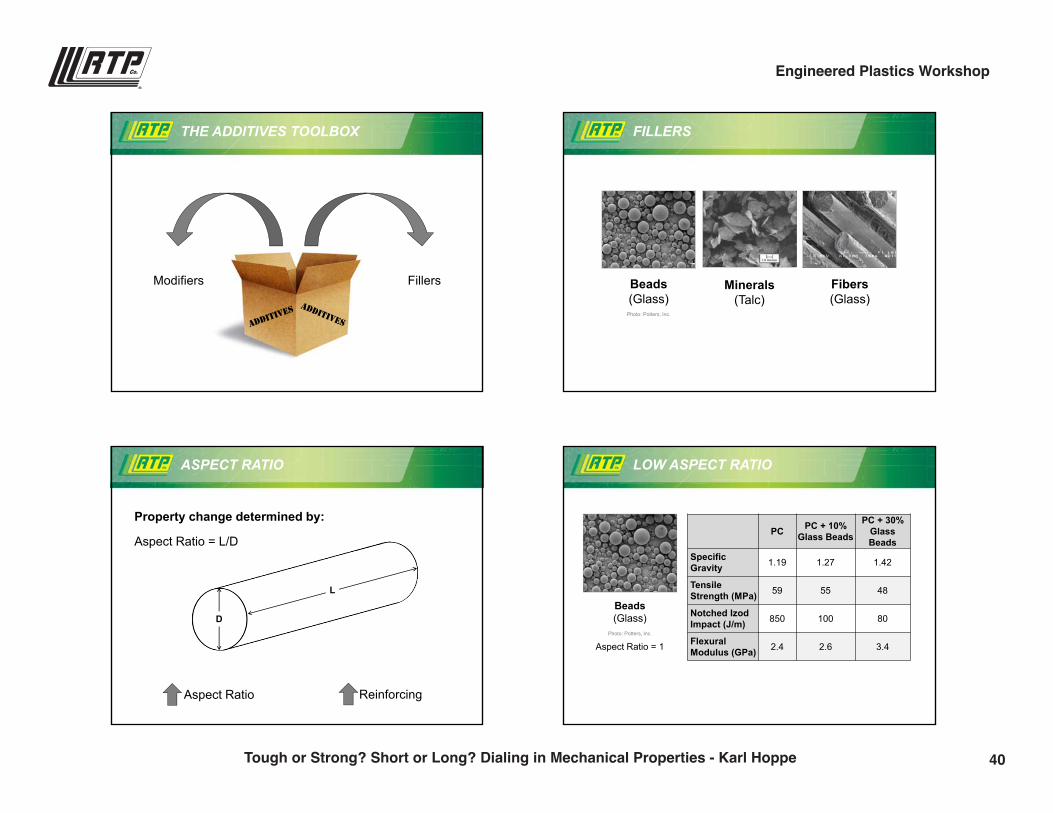
THE ADDITIVES TOOLBOX
Modifiers Fillers
FILLERS
Beads(Glass)
Photo: Potters, Inc.
Minerals(Talc)
Fibers(Glass)
ASPECT RATIO
Property change determined by:
Aspect Ratio Reinforcing
Aspect Ratio = L/D
L
D
LOW ASPECT RATIO
Beads(Glass)
Photo: Potters, Inc.
Aspect Ratio = 1
PC PC + 10% Glass Beads
PC + 30% GlassBeads
SpecificGravity 1.19 1.27 1.42
Tensile Strength (MPa) 59 55 48
Notched IzodImpact (J/m) 850 100 80
FlexuralModulus (GPa) 2.4 2.6 3.4
40Tough or Strong? Short or Long? Dialing in Mechanical Properties - Karl Hoppe
Engineered Plastics Workshop
9/28/2016
6
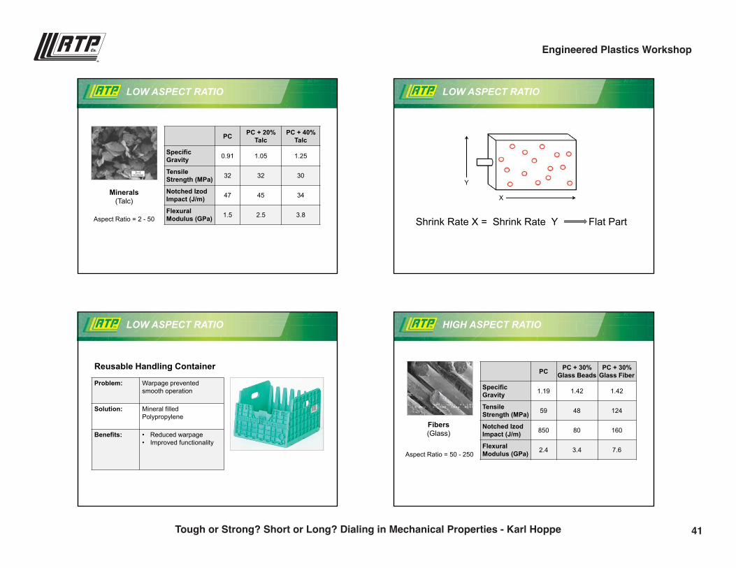
Minerals(Talc)
Aspect Ratio = 2 - 50
PC PC + 20% Talc
PC + 40% Talc
SpecificGravity 0.91 1.05 1.25
Tensile Strength (MPa) 32 32 30
Notched IzodImpact (J/m) 47 45 34
FlexuralModulus (GPa) 1.5 2.5 3.8
LOW ASPECT RATIO
Shrink Rate X = Shrink Rate Y Flat Part
LOW ASPECT RATIO
X
Y
LOW ASPECT RATIO
Reusable Handling Container
Problem: Warpage prevented smooth operation
Solution: Mineral filled Polypropylene
Benefits: • Reduced warpage• Improved functionality
HIGH ASPECT RATIO
PC PC + 30% Glass Beads
PC + 30% Glass Fiber
SpecificGravity 1.19 1.42 1.42
Tensile Strength (MPa) 59 48 124
Notched IzodImpact (J/m) 850 80 160
FlexuralModulus (GPa) 2.4 3.4 7.6
Fibers(Glass)
Aspect Ratio = 50 - 250
41Tough or Strong? Short or Long? Dialing in Mechanical Properties - Karl Hoppe
Engineered Plastics Workshop
9/28/2016
7
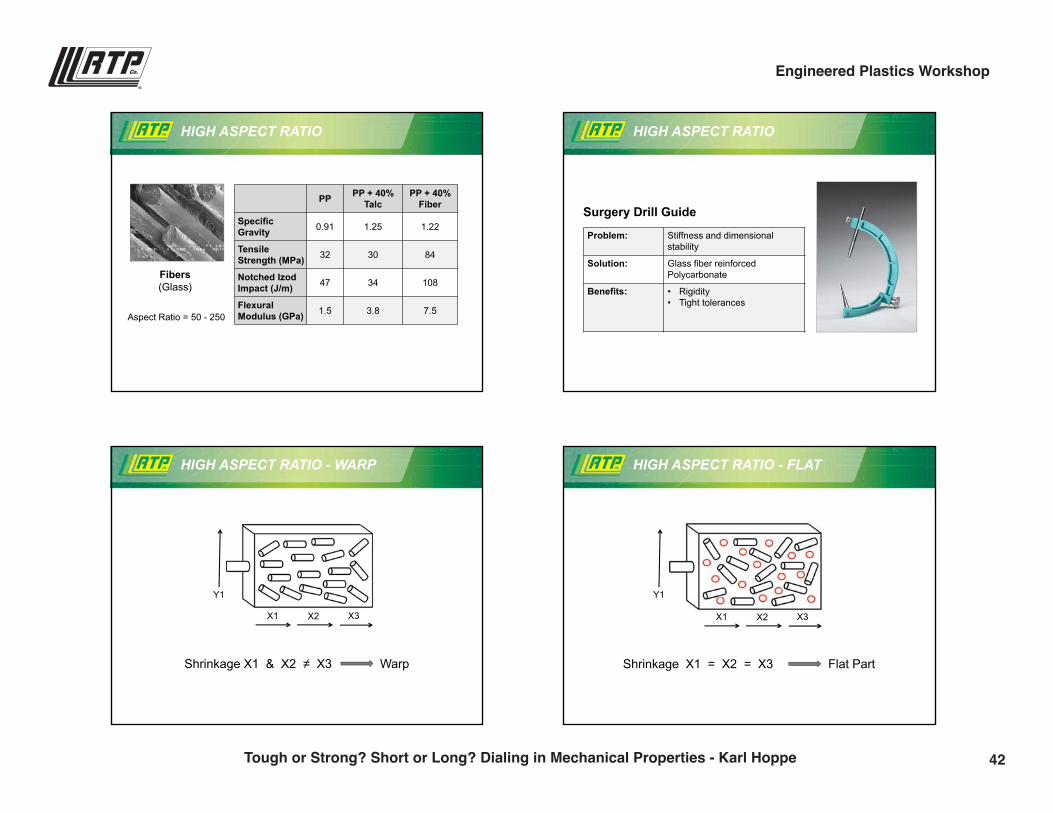
Fibers(Glass)
HIGH ASPECT RATIO
PP PP + 40% Talc
PP + 40% Fiber
SpecificGravity 0.91 1.25 1.22
Tensile Strength (MPa) 32 30 84
Notched IzodImpact (J/m) 47 34 108
FlexuralModulus (GPa) 1.5 3.8 7.5
Aspect Ratio = 50 - 250
HIGH ASPECT RATIO
Surgery Drill Guide
Problem: Stiffness and dimensional stability
Solution: Glass fiber reinforced Polycarbonate
Benefits: • Rigidity• Tight tolerances
HIGH ASPECT RATIO - WARP
Shrinkage X1 & X2 ≠ X3 Warp
Y1
X1 X2 X3
Shrinkage X1 = X2 = X3 Flat Part
HIGH ASPECT RATIO - FLAT
Y1
X1 X2 X3
42Tough or Strong? Short or Long? Dialing in Mechanical Properties - Karl Hoppe
Engineered Plastics Workshop
9/28/2016
8
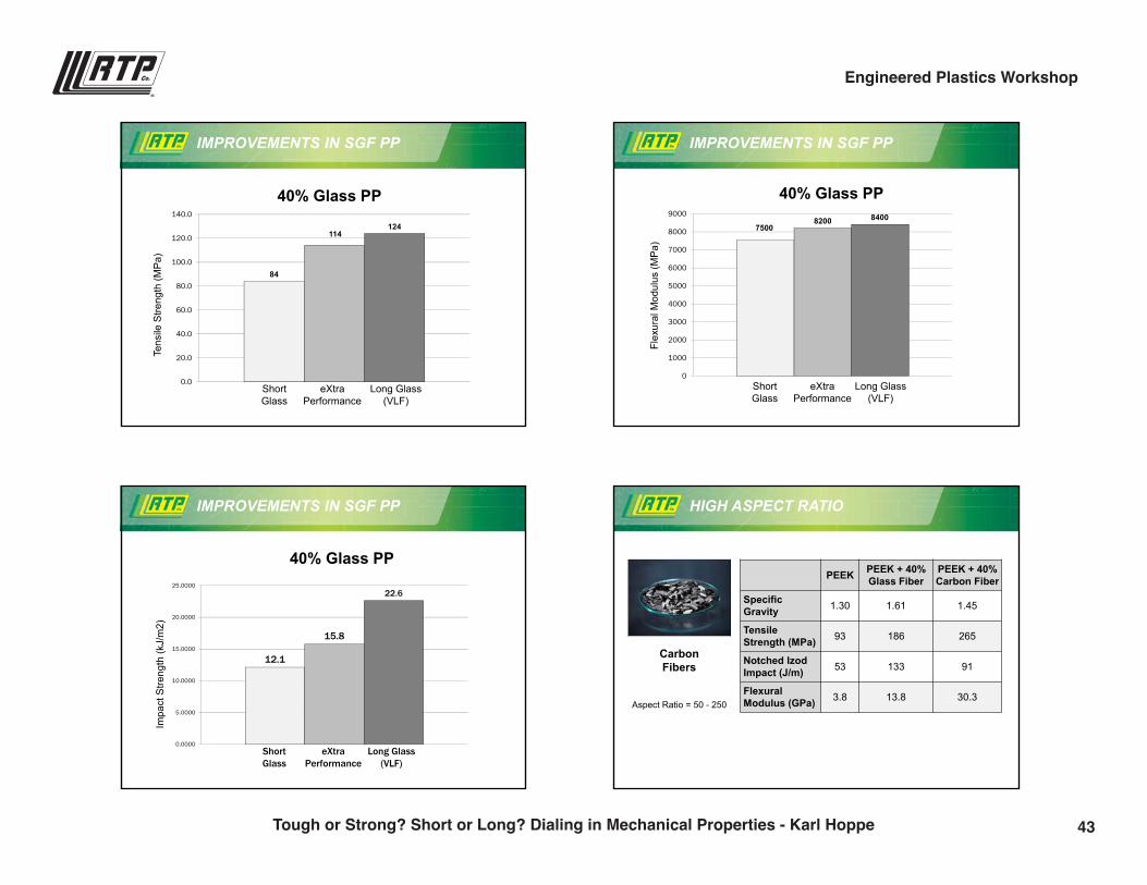
IMPROVEMENTS IN SGF PP
84
114124
0.0
20.0
40.0
60.0
80.0
100.0
120.0
140.0
Tens
ile S
treng
th (M
Pa)
40% Glass PP
Short Glass
Long Glass (VLF)
eXtraPerformance
IMPROVEMENTS IN SGF PP
75008200 8400
0
1000
2000
3000
4000
5000
6000
7000
8000
9000
Flex
ural
Mod
ulus
(MP
a)
40% Glass PP
Short Glass
Long Glass (VLF)
eXtraPerformance
IMPROVEMENTS IN SGF PP
12.1
15.8
22.6
0.0000
5.0000
10.0000
15.0000
20.0000
25.0000
Impa
ct S
treng
th (k
J/m
2)
40% Glass PP
ShortGlass
Long Glass (VLF)
eXtraPerformance
HIGH ASPECT RATIO
Carbon Fibers
Aspect Ratio = 50 - 250
PEEK PEEK + 40% Glass Fiber
PEEK + 40% Carbon Fiber
SpecificGravity 1.30 1.61 1.45
Tensile Strength (MPa) 93 186 265
Notched IzodImpact (J/m) 53 133 91
FlexuralModulus (GPa) 3.8 13.8 30.3
43Tough or Strong? Short or Long? Dialing in Mechanical Properties - Karl Hoppe
Engineered Plastics Workshop
9/28/2016
9
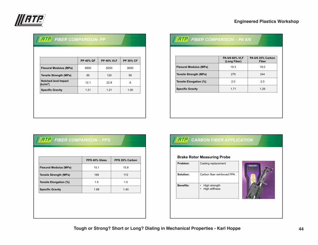
FIBER COMPARISON- PP
PP 40% GF PP 40% VLF PP 30% CF
Flexural Modulus (MPa) 6900 8250 9000
Tensile Strength (MPa) 85 120 90
Notched Izod Impact (kJ/m2) 12.1 22.8 6
Specific Gravity 1.21 1.21 1.00
FIBER COMPARISON – PA 6/6
PA 6/6 60% VLF (Long Fiber)
PA 6/6 35% Carbon Fiber
Flexural Modulus (MPa) 19.3 19.0
Tensile Strength (MPa) 275 244
Tensile Elongation (%) 2.0 2.0
Specific Gravity 1.71 1.29
FIBER COMPARISON – PPS
PPS 40% Glass PPS 20% Carbon
Flexural Modulus (MPa) 15.1 15.8
Tensile Strength (MPa) 169 172
Tensile Elongation (%) 1.5 1.0
Specific Gravity 1.68 1.40
CARBON FIBER APPLICATION
Brake Rotor Measuring ProbeProblem: Casting replacement
Solution: Carbon fiber reinforced PPA
Benefits: • High strength• High stiffness
44Tough or Strong? Short or Long? Dialing in Mechanical Properties - Karl Hoppe
Engineered Plastics Workshop
9/28/2016
10
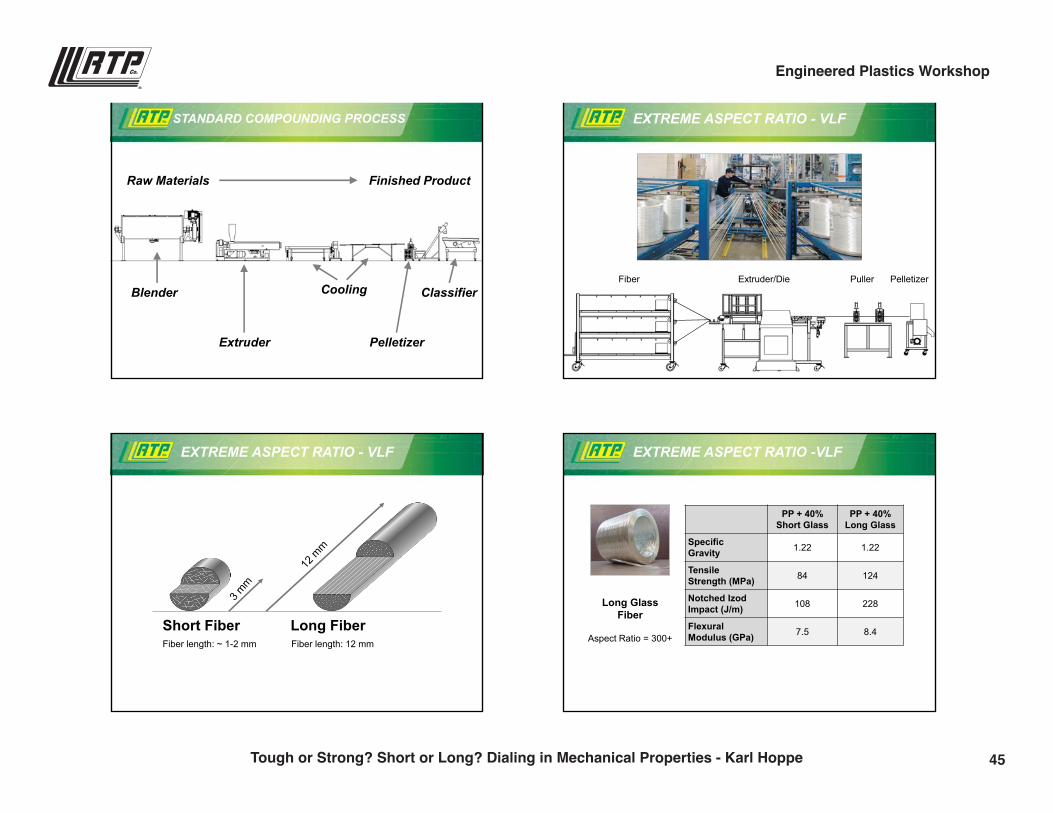
STANDARD COMPOUNDING PROCESS
Cooling
Extruder
Blender
Pelletizer
Classifier
Raw Materials Finished Product
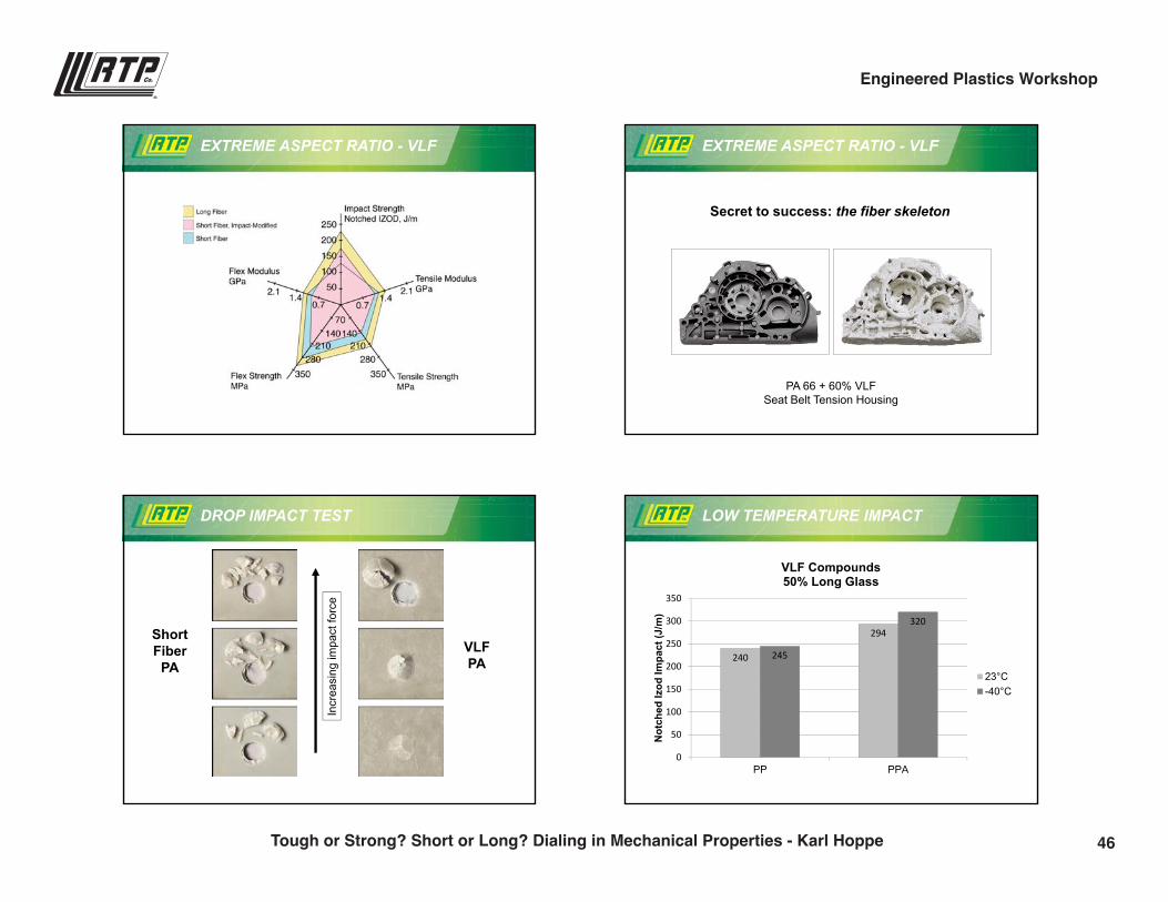
EXTREME ASPECT RATIO - VLF
Fiber Extruder/Die Puller Pelletizer
EXTREME ASPECT RATIO - VLF
Fiber length: ~ 1-2 mm
Short Fiber Long FiberFiber length: 12 mm
EXTREME ASPECT RATIO -VLF
Long Glass Fiber
Aspect Ratio = 300+
PP + 40% Short Glass
PP + 40% Long Glass
SpecificGravity 1.22 1.22
Tensile Strength (MPa) 84 124
Notched IzodImpact (J/m) 108 228
FlexuralModulus (GPa) 7.5 8.4
45Tough or Strong? Short or Long? Dialing in Mechanical Properties - Karl Hoppe
Engineered Plastics Workshop
9/28/2016
11
EXTREME ASPECT RATIO - VLF EXTREME ASPECT RATIO - VLF
PA 66 + 60% VLFSeat Belt Tension Housing
Secret to success: the fiber skeleton
DROP IMPACT TEST
Incr
easi
ng im
pact
forc
e
ShortFiber
PAVLFPA
LOW TEMPERATURE IMPACT
240
294
245
320
0
50
100
150
200
250
300
350
PP PPA
Not
ched
Izod
Impa
ct (J
/m)
VLF Compounds50% Long Glass
23°C-40°C
46Tough or Strong? Short or Long? Dialing in Mechanical Properties - Karl Hoppe
Engineered Plastics Workshop
9/28/2016
12
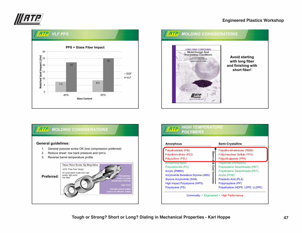
VLF PPS
7.5 8.5
2225
0
5
10
15
20
25
30
40% 50%
Not
ched
Izod
Impa
ct (J
/m)
Glass Content
PPS + Glass Fiber Impact
SGFVLF
MOLDING CONSIDERATIONS
Avoid starting with long fiber
and finishing with short fiber!
MOLDING CONSIDERATIONS
General guidelines:1. General purpose screw OK (low compression preferred)2. Reduce shear: low back pressure and rpm’s3. Reverse barrel temperature profile
Preferred:
Amorphous Semi-Crystalline
Polyetherimide (PEI)Polyethersulfone (PES)Polysulfone (PSU)Amorphous NylonPolycarbonate (PC)Acrylic (PMMA)Acrylonitrile Butadiene Styrene (ABS)Styrene Acrylonitrile (SAN)High Impact Polystyrene (HIPS)Polystyrene (PS)
Polyetheretherketone (PEEK)Polyphenylene Sulfide (PPS)Polyphthalamide (PPA)Polyamide (PA/Nylons)Polybutylene Terephthalate (PBT)Polyethylene Terephthalate (PET)Acetal (POM)Polylactic Acid (PLA)Polypropylene (PP)Polyethylene (HDPE, LDPE, LLDPE)
Thermal &
Cost Increases
Commodity • Engineered • High Performance
HIGH TEMPERATURE POLYMERS
47Tough or Strong? Short or Long? Dialing in Mechanical Properties - Karl Hoppe
Engineered Plastics Workshop
9/28/2016
13
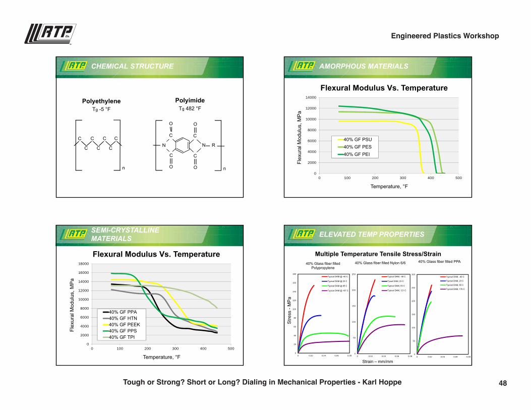
CHEMICAL STRUCTURE
PolyethyleneTg -5 °F
C C C
C C C C
n
PolyimideTg 482 °F
n
N N
C
C C
R
O O
O O
C
AMORPHOUS MATERIALS
0
2000
4000
6000
8000
10000
12000
14000
0 100 200 300 400 500
Flex
ural
Mod
ulus
, MP
a
Temperature, °F
Flexural Modulus Vs. Temperature
40% GF PSU40% GF PES40% GF PEI
SEMI-CRYSTALLINE MATERIALS
0
2000
4000
6000
8000
10000
12000
14000
16000
18000
0 100 200 300 400 500
Flex
ural
Mod
ulus
, MP
a
Temperature, °F
Flexural Modulus Vs. Temperature
40% GF PPA40% GF HTN40% GF PEEK40% GF PPS40% GF TPI
ELEVATED TEMP PROPERTIES
0
20
40
60
80
100
120
140
160
180
0 0.02 0.04 0.06 0.08
40% Glass fiber filled Polypropylene
Typical DAM @ -40 C
Typical DAM @ 23 C
Typical DAM @ 65 C
Typical DAM @ 107 C
0
50
100
150
200
250
0 0.02 0.04 0.06 0.08
40% Glass fiber filled Nylon 6/6
Typical DAM, -40 C
Tyical DAM, 23 C
Typical DAM, 65 C
Typical DAM, 121 C
0
50
100
150
200
250
300
0 0.02 0.04 0.06 0.08
40% Glass fiber filled PPA
Typical DAM, -40 C
Typical DAM, 23 C
Typical DAM, 65 C
Typical DAM, 176 C
Strain – mm/mm
Stre
ss -
MP
a
Multiple Temperature Tensile Stress/Strain
48Tough or Strong? Short or Long? Dialing in Mechanical Properties - Karl Hoppe
Engineered Plastics Workshop
9/28/2016
14
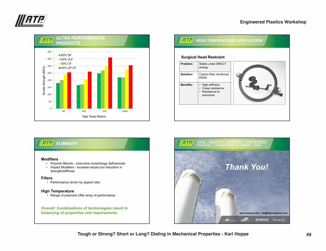
ULTRA PERFORMANCE PRODUCTS
0
50
100
150
200
250
300
350
400
PEI PPS PPA PEEK
Tens
ile S
treng
th (M
Pa)
High Temp Resins
50% GF50% VLF40% CF40% UP CF
HIGH TEMPERATURE APPLICATION
Surgical Head RestraintProblem: Stable under MRI/CT
energy
Solution: Carbon fiber reinforced PEEK
Benefits: • High stiffness• Creep resistance• Resistance to
autoclave
SUMMARY
Modifiers• Polymer Blends - overcome morphology deficiencies• Impact Modifiers - increase impact but reduction in
strength/stiffness
Fillers• Performance driven by aspect ratio
High Temperature• Range of polymers offer array of performance
Overall: Combinations of technologies result in balancing of properties and requirements rtpcompany.com [email protected]
Thank You!
49Tough or Strong? Short or Long? Dialing in Mechanical Properties - Karl Hoppe
Engineered Plastics Workshop
Answers to Your Burning Questions: Flame Retardants and Regulations
Jesse Dulek | Product Development [email protected](507) 474-5502
11:00 p.m.51
9/28/2016
1
rtpcompany.com [email protected]
Jesse DulekProduct Development Engineer,Flame Retardant Products
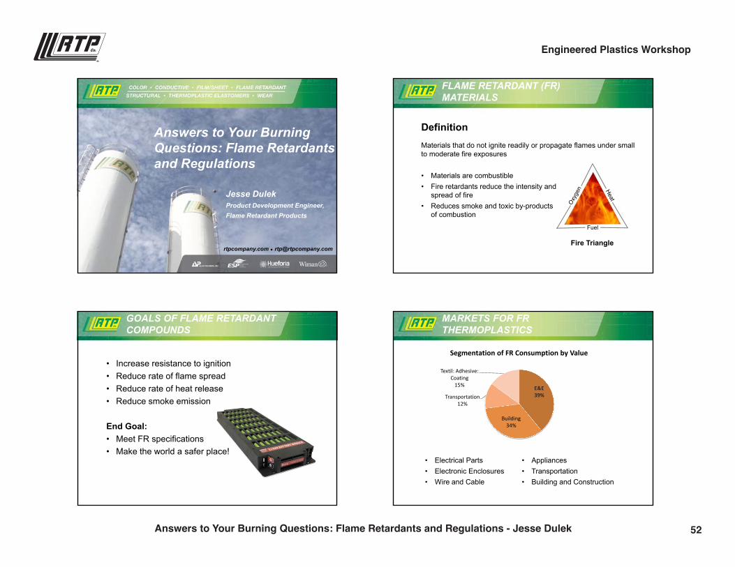
Answers to Your Burning Questions: Flame Retardants and Regulations
FLAME RETARDANT (FR) MATERIALS
DefinitionMaterials that do not ignite readily or propagate flames under small to moderate fire exposures
• Materials are combustible• Fire retardants reduce the intensity and
spread of fire• Reduces smoke and toxic by-products
of combustion
Fire Triangle
Fuel
GOALS OF FLAME RETARDANT COMPOUNDS
• Increase resistance to ignition• Reduce rate of flame spread• Reduce rate of heat release• Reduce smoke emission
End Goal:• Meet FR specifications• Make the world a safer place!
MARKETS FOR FRTHERMOPLASTICS
E&E39%
Building34%
Transportation12%
Textil: Adhesive: Coating
15%
Segmentation of FR Consumption by Value
• Electrical Parts• Electronic Enclosures• Wire and Cable
• Appliances• Transportation• Building and Construction
52Answers to Your Burning Questions: Flame Retardants and Regulations - Jesse Dulek
Engineered Plastics Workshop
9/28/2016
2
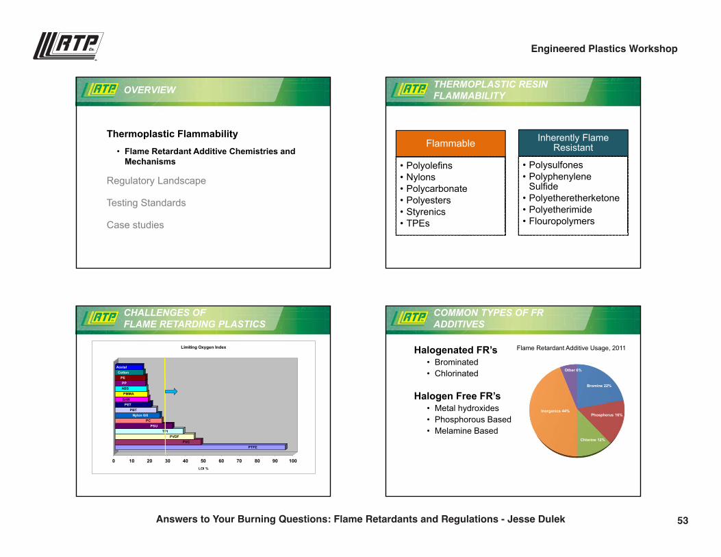
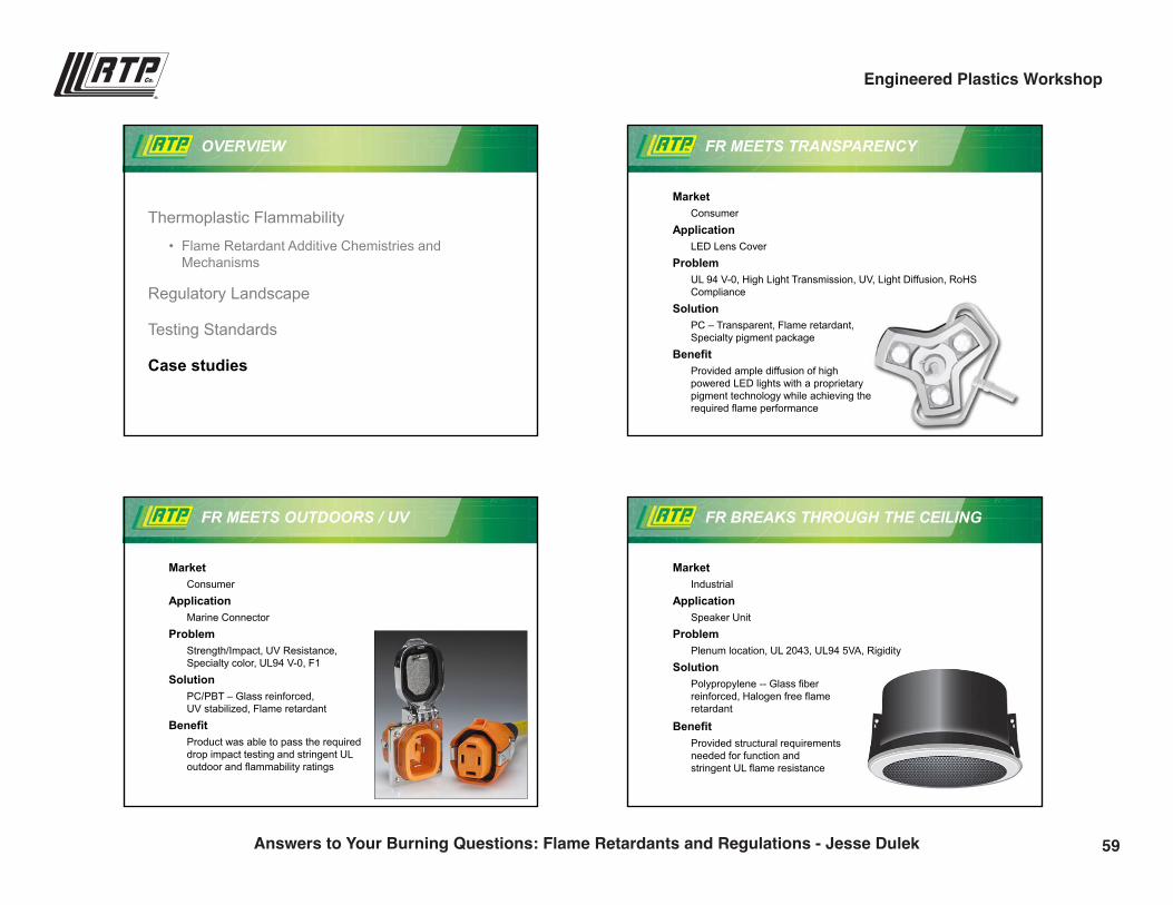
OVERVIEW
Thermoplastic Flammability• Flame Retardant Additive Chemistries and
Mechanisms
Regulatory Landscape
Testing Standards
Case studies
THERMOPLASTIC RESIN FLAMMABILITY
Flammable
• Polyolefins• Nylons• Polycarbonate• Polyesters• Styrenics• TPEs
Inherently Flame Resistant
• Polysulfones• Polyphenylene
Sulfide• Polyetheretherketone• Polyetherimide• Flouropolymers
CHALLENGES OF FLAME RETARDING PLASTICS
PTFE PVC
PVDFTPI
PSUPC
Nylon 6/6PBT
PETSANPMMA
ABSPP
PECotton
Acetal
0 10 20 30 40 50 60 70 80 90 100LOI %
Limiting Oxygen Index
COMMON TYPES OF FRADDITIVES
Bromine 22%
Phosphorus 16%
Chlorine 12%
Inorganics 44%
Other 6%
Flame Retardant Additive Usage, 2011Halogenated FR’s • Brominated• Chlorinated
Halogen Free FR’s• Metal hydroxides• Phosphorous Based• Melamine Based
53Answers to Your Burning Questions: Flame Retardants and Regulations - Jesse Dulek
Engineered Plastics Workshop
9/28/2016
3
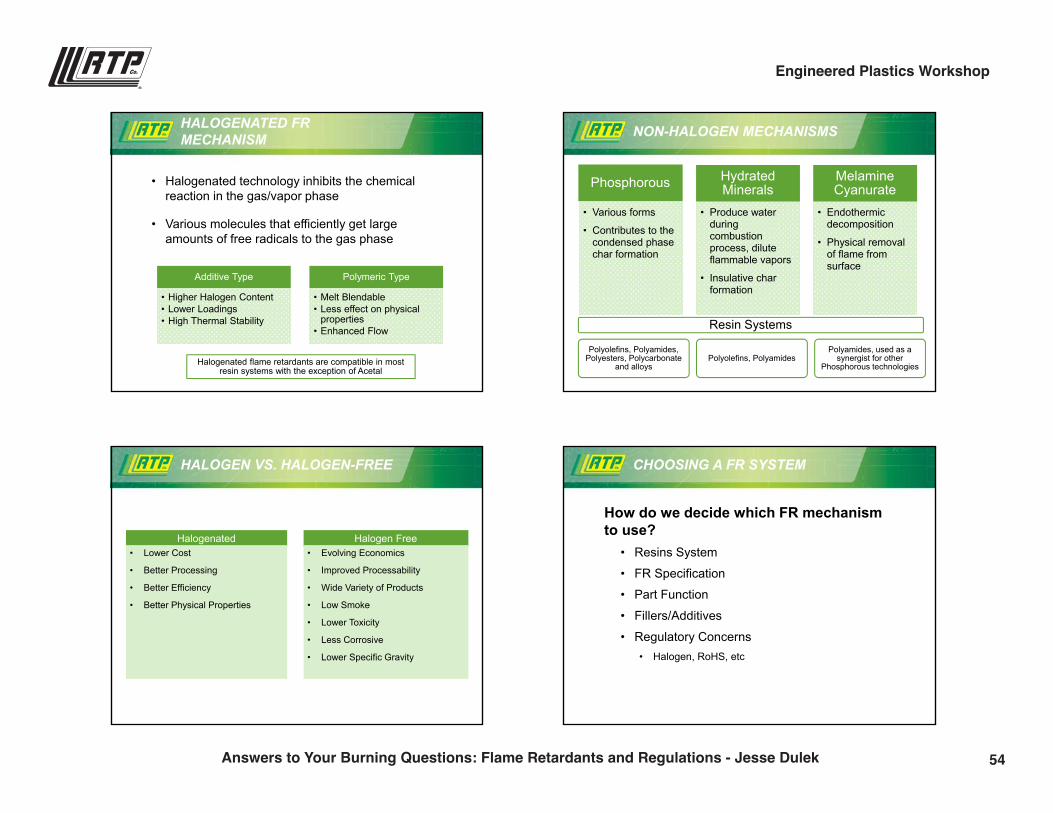
HALOGENATED FRMECHANISM
• Halogenated technology inhibits the chemical reaction in the gas/vapor phase
• Various molecules that efficiently get large amounts of free radicals to the gas phase
Additive Type
• Higher Halogen Content• Lower Loadings• High Thermal Stability
Polymeric Type
• Melt Blendable• Less effect on physical
properties• Enhanced Flow
Halogenated flame retardants are compatible in most resin systems with the exception of Acetal
NON-HALOGEN MECHANISMS
Phosphorous
• Various forms
• Contributes to the condensed phase char formation
HydratedMinerals
• Produce water duringcombustionprocess, dilute flammable vapors
• Insulative char formation
MelamineCyanurate
• Endothermic decomposition
• Physical removal of flame from surface
Resin Systems
Polyolefins, Polyamides, Polyesters, Polycarbonate
and alloys Polyolefins, Polyamides
Polyamides, used as a synergist for other
Phosphorous technologies
HALOGEN VS. HALOGEN-FREE
Halogen FreeHalogenated• Lower Cost
• Better Processing
• Better Efficiency
• Better Physical Properties
• Evolving Economics
• Improved Processability
• Wide Variety of Products
• Low Smoke
• Lower Toxicity
• Less Corrosive
• Lower Specific Gravity
CHOOSING A FR SYSTEM
How do we decide which FR mechanism to use?
• Resins System
• FR Specification
• Part Function
• Fillers/Additives
• Regulatory Concerns• Halogen, RoHS, etc
54Answers to Your Burning Questions: Flame Retardants and Regulations - Jesse Dulek
Engineered Plastics Workshop
9/28/2016
4
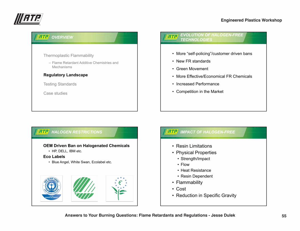
OVERVIEW
Thermoplastic Flammability
– Flame Retardant Additive Chemistries and Mechanisms
Regulatory Landscape
Testing Standards
Case studies
EVOLUTION OF HALOGEN-FREE TECHNOLOGIES
• More “self-policing”/customer driven bans
• New FR standards
• Green Movement
• More Effective/Economical FR Chemicals
• Increased Performance
• Competition in the Market
HALOGEN RESTRICTIONS
OEM Driven Ban on Halogenated Chemicals• HP, DELL, IBM etc.
Eco Labels• Blue Angel, White Swan, Ecolabel etc.
IMPACT OF HALOGEN-FREE
• Resin Limitations• Physical Properties
• Strength/Impact• Flow• Heat Resistance• Resin Dependent
• Flammability• Cost• Reduction in Specific Gravity
55Answers to Your Burning Questions: Flame Retardants and Regulations - Jesse Dulek
Engineered Plastics Workshop
9/28/2016
5
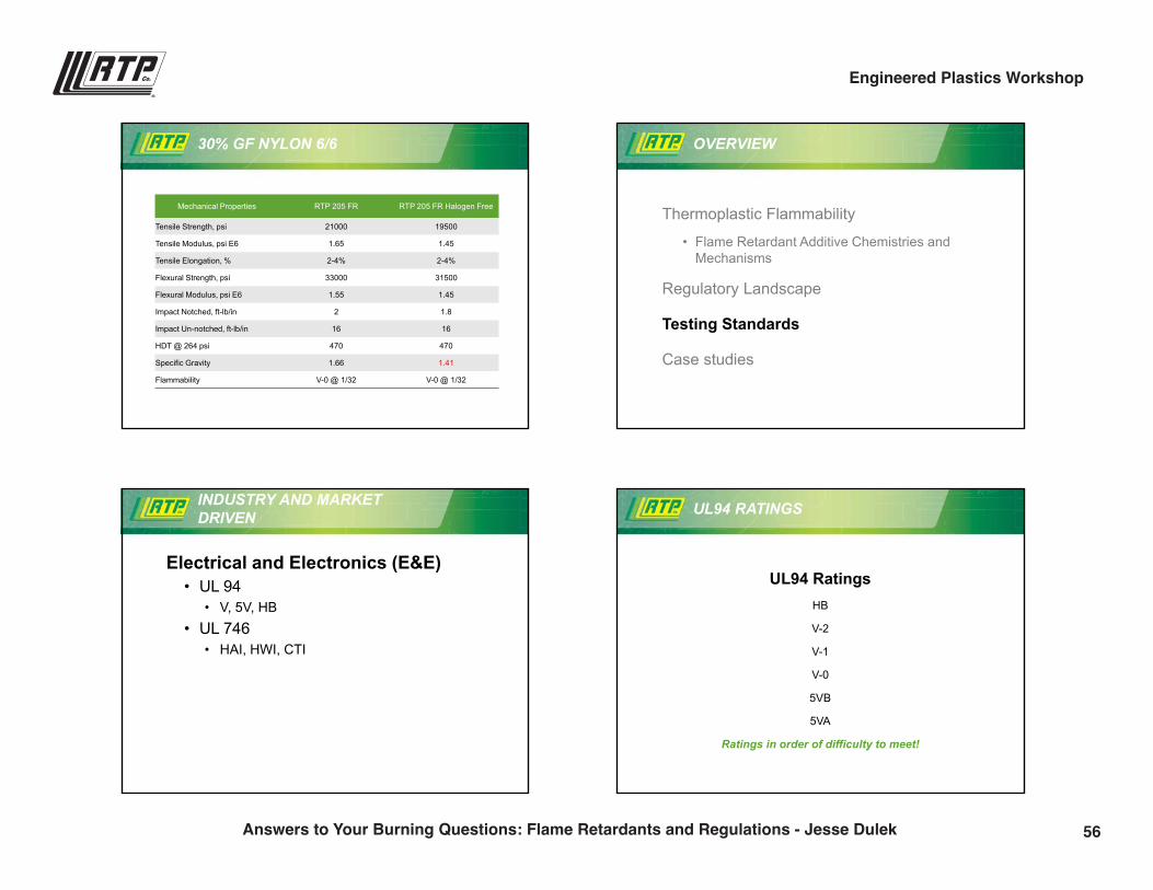
30% GF NYLON 6/6
Mechanical Properties RTP 205 FR RTP 205 FR Halogen Free
Tensile Strength, psi 21000 19500
Tensile Modulus, psi E6 1.65 1.45
Tensile Elongation, % 2-4% 2-4%
Flexural Strength, psi 33000 31500
Flexural Modulus, psi E6 1.55 1.45
Impact Notched, ft-lb/in 2 1.8
Impact Un-notched, ft-lb/in 16 16
HDT @ 264 psi 470 470
Specific Gravity 1.66 1.41
Flammability V-0 @ 1/32 V-0 @ 1/32
OVERVIEW
Thermoplastic Flammability
• Flame Retardant Additive Chemistries and Mechanisms
Regulatory Landscape
Testing Standards
Case studies
INDUSTRY AND MARKET DRIVEN
Electrical and Electronics (E&E) • UL 94
• V, 5V, HB• UL 746
• HAI, HWI, CTI
UL94 RATINGS
UL94 RatingsHB
V-2
V-1
V-0
5VB
5VA
Ratings in order of difficulty to meet!
56Answers to Your Burning Questions: Flame Retardants and Regulations - Jesse Dulek
Engineered Plastics Workshop
9/28/2016
6
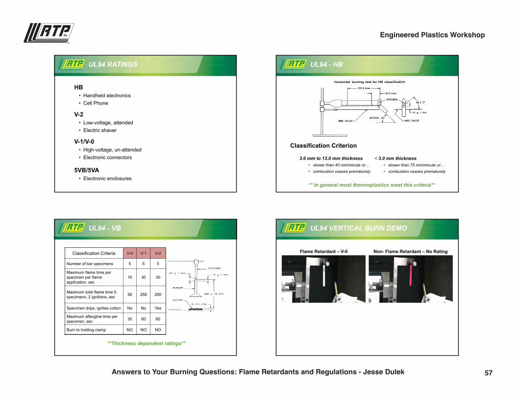
UL94 RATINGS
HB• Handheld electronics • Cell Phone
V-2• Low-voltage, attended• Electric shaver
V-1/V-0• High-voltage, un-attended• Electronic connectors
5VB/5VA• Electronic enclosures
UL94 - HB
Classification Criterion
3.0 mm to 13.0 mm thickness• slower than 40 mm/minute or…• combustion ceases prematurely
< 3.0 mm thickness• slower than 75 mm/minute or…• combustion ceases prematurely
** In general most thermoplastics meet this criteria**
UL94 - VB
Classification Criteria V-0 V-1 V-2
Number of bar specimens 5 5 5
Maximum flame time per specimen per flame application, sec
10 30 30
Maximum total flame time 5 specimens, 2 ignitions, sec 50 250 250
Specimen drips, ignites cotton No No Yes
Maximum afterglow time per specimen, sec 30 60 60
Burn to holding clamp NO NO NO
**Thickness dependent ratings**
UL94 VERTICAL BURN DEMO
Flame Retardant – V-0 Non- Flame Retardant – No Rating
57Answers to Your Burning Questions: Flame Retardants and Regulations - Jesse Dulek
Engineered Plastics Workshop
9/28/2016
7
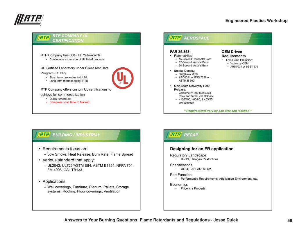
RTP Company has 600+ UL Yellowcards• Continuous expansion of UL listed products
UL Certified Laboratory under Client Test Data Program (CTDP)
• Short term properties to UL94 • Long term thermal aging (RTI)
RTP Company offers custom UL certifications to achieve full commercialization
• Quick turnaround • Compress your Time to Market!
RTP COMPANY ULCERTIFICATION AEROSPACE
FAR 25.853• Flammability:
– 15-Second Horizontal Burn– 12-Second Vertical Burn– 60-Second Vertical Burn
• Smoke Density:– Ds@4min <200– ABD0031 or BSS 7238 or
ASTM E-662
• Ohio State University Heat Release:– Calorimetry Test Measures
Peak and Total Heat Release– <100/100, <65/65, & <55/55
are common
OEM Driven Requirements• Toxic Gas Emission:
– Varies by OEM– ABD0031 or BSS 7239
**Requirements vary by part size and location**
BUILDING / INDUSTRIAL
• Requirements focus on:– Low Smoke, Heat Release, Burn Rate, Flame Spread
• Various standard that apply:– UL2043, UL723/ASTM E84, ASTM E1354, NFPA 701,
FM 4996, CAL TB133
• Applications– Wall coverings, Furniture, Plenum, Pallets, Storage
systems, Roofing, Floor coverings, Ventilation
RECAP
Designing for an FR applicationRegulatory Landscape
• RoHS, Halogen Restrictions
Specifications• UL94, FAR, ASTM, etc.
Part Function• Performance Requirements, Application Environment, etc.
Economics• Price is a Property
58Answers to Your Burning Questions: Flame Retardants and Regulations - Jesse Dulek
Engineered Plastics Workshop
9/28/2016
8
OVERVIEW
Thermoplastic Flammability
• Flame Retardant Additive Chemistries and Mechanisms
Regulatory Landscape
Testing Standards
Case studies
FR MEETS TRANSPARENCY
MarketConsumer
ApplicationLED Lens Cover
ProblemUL 94 V-0, High Light Transmission, UV, Light Diffusion, RoHS Compliance
SolutionPC – Transparent, Flame retardant, Specialty pigment package
BenefitProvided ample diffusion of high powered LED lights with a proprietary pigment technology while achieving the required flame performance
FR MEETS OUTDOORS / UV
MarketConsumer
ApplicationMarine Connector
ProblemStrength/Impact, UV Resistance, Specialty color, UL94 V-0, F1
SolutionPC/PBT – Glass reinforced, UV stabilized, Flame retardant
BenefitProduct was able to pass the required drop impact testing and stringent UL outdoor and flammability ratings
FR BREAKS THROUGH THE CEILING
MarketIndustrial
ApplicationSpeaker Unit
ProblemPlenum location, UL 2043, UL94 5VA, Rigidity
SolutionPolypropylene -- Glass fiber reinforced, Halogen free flame retardant
BenefitProvided structural requirements needed for function and stringent UL flame resistance
59Answers to Your Burning Questions: Flame Retardants and Regulations - Jesse Dulek
Engineered Plastics Workshop
9/28/2016
9
rtpcompany.com [email protected]
Thank You!
Jesse [email protected](507) 474-5502
60Answers to Your Burning Questions: Flame Retardants and Regulations - Jesse Dulek
Engineered Plastics Workshop
Live in the Wall Section: Product Design Principles for Structural Composites
Barbara Matousek | CAE [email protected](507) 474-5301
12:45 p.m.
61
9/28/2016
1
rtpcompany.com [email protected]
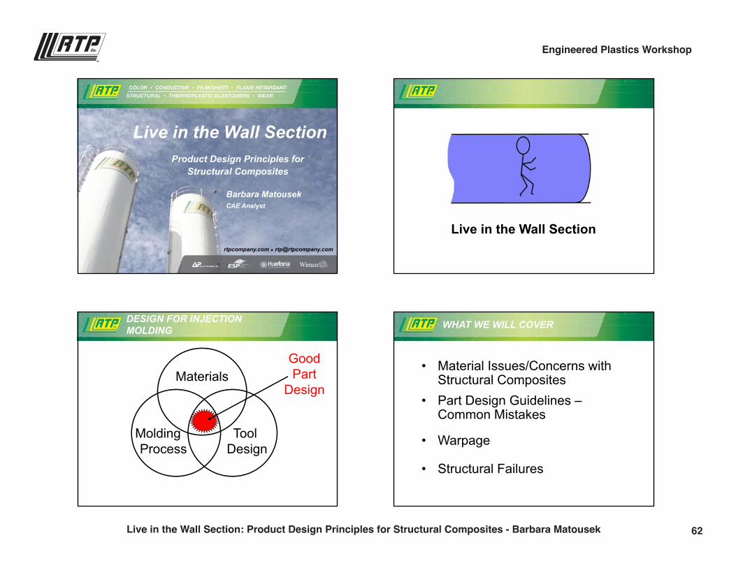
Live in the Wall SectionProduct Design Principles for
Structural Composites
Barbara MatousekCAE Analyst
Live in the Wall Section
DESIGN FOR INJECTION MOLDING
Materials
Molding Process
Tool Design
GoodPart
Design
WHAT WE WILL COVER
• Material Issues/Concerns with Structural Composites
• Part Design Guidelines –Common Mistakes
• Warpage
• Structural Failures
62Live in the Wall Section: Product Design Principles for Structural Composites - Barbara Matousek
Engineered Plastics Workshop
9/28/2016
2
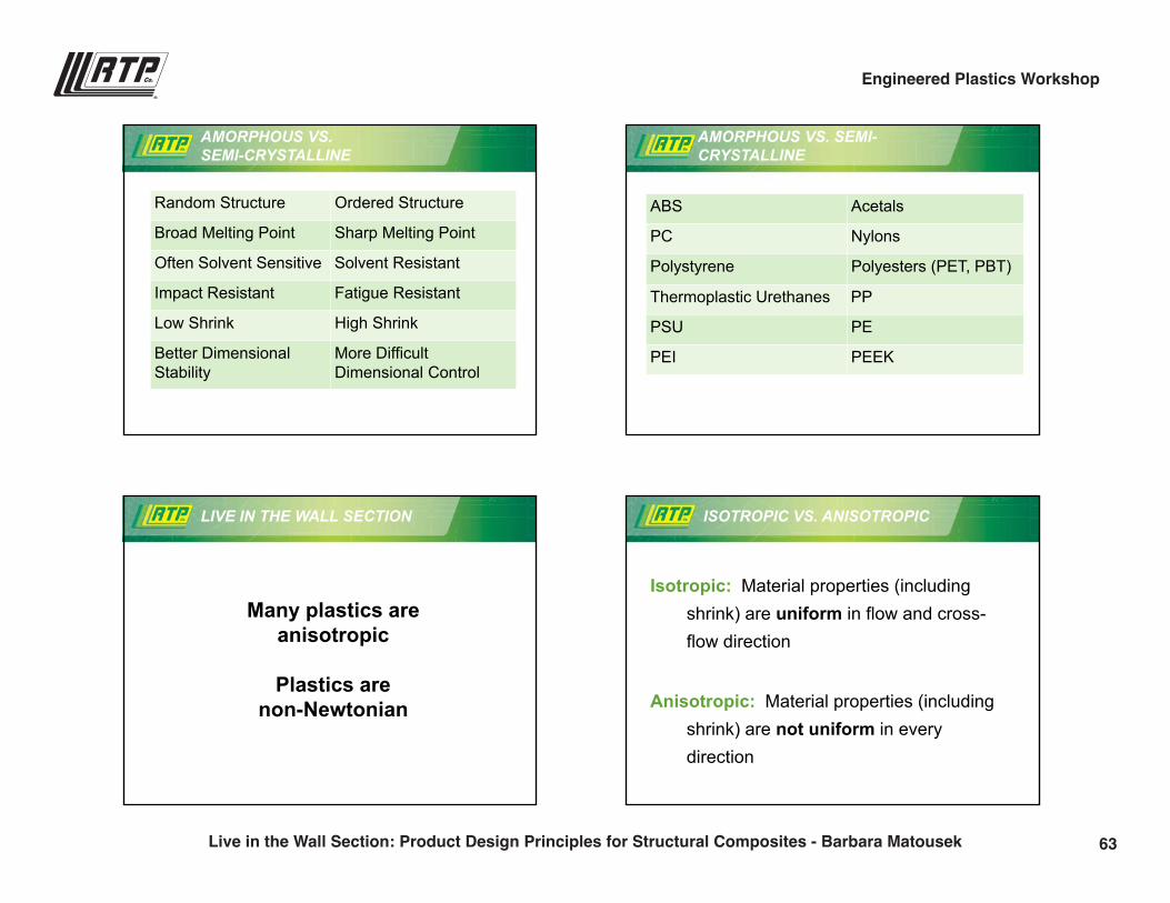
AMORPHOUS VS. SEMI-CRYSTALLINE
Random Structure Ordered Structure
Broad Melting Point Sharp Melting Point
Often Solvent Sensitive Solvent Resistant
Impact Resistant Fatigue Resistant
Low Shrink High Shrink
Better Dimensional Stability
More Difficult Dimensional Control
ABS Acetals
PC Nylons
Polystyrene Polyesters (PET, PBT)
Thermoplastic Urethanes PP
PSU PE
PEI PEEK
AMORPHOUS VS. SEMI-CRYSTALLINE
LIVE IN THE WALL SECTION
Many plastics are anisotropic
Plastics are non-Newtonian
ISOTROPIC VS. ANISOTROPIC
Isotropic: Material properties (including shrink) are uniform in flow and cross-flow direction
Anisotropic: Material properties (including shrink) are not uniform in every direction
63Live in the Wall Section: Product Design Principles for Structural Composites - Barbara Matousek
Engineered Plastics Workshop
9/28/2016
3
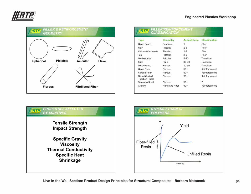
FILLER & REINFORCEMENT GEOMETRY
Spherical Platelets Acicular Flake
Fibrous Fibrillated Fiber
FILLER/REINFORCEMENT CLASSIFICATION
TypeGlass BeadsClayCalcium CarbonateTalcWollastoniteMicaMilled GlassGlass FiberCarbon FiberNickel CoatedCarbon Fibers
Stainless SteelAramid
GeometrySphericalPlateletPlateletPlateletAcicularFlakeFibrousFibrousFibrousFibrous
FibrousFibrillated Fiber
Aspect Ratio11-31-32-55-2030-5010-5050+50+50+
50+50+
ClassificationFillerFillerFillerFillerTransitionTransitionTransitionReinforcementReinforcementReinforcement
?Reinforcement
PROPERTIES AFFECTED BY ADDITIVES
Tensile StrengthImpact Strength
Specific GravityViscosity
Thermal ConductivitySpecific Heat
Shrinkage
STRESS-STRAIN OF POLYMERS
Unfilled Resin
Yield
Fiber-filledResin
64Live in the Wall Section: Product Design Principles for Structural Composites - Barbara Matousek
Engineered Plastics Workshop
9/28/2016
4
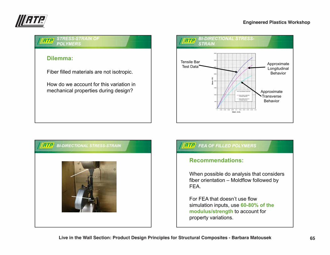
STRESS-STRAIN OF POLYMERS
Dilemma:
Fiber filled materials are not isotropic.
How do we account for this variation in mechanical properties during design?
BI-DIRECTIONAL STRESS-STRAIN
Tensile BarTest Data
ApproximateLongitudinal
Behavior
ApproximateTransverseBehavior
BI-DIRECTIONAL STRESS-STRAIN FEA OF FILLED POLYMERS
Recommendations:
When possible do analysis that considers fiber orientation – Moldflow followed by FEA.
For FEA that doesn’t use flow simulation inputs, use 60-80% of the modulus/strength to account for property variations.
65Live in the Wall Section: Product Design Principles for Structural Composites - Barbara Matousek
Engineered Plastics Workshop
9/28/2016
5
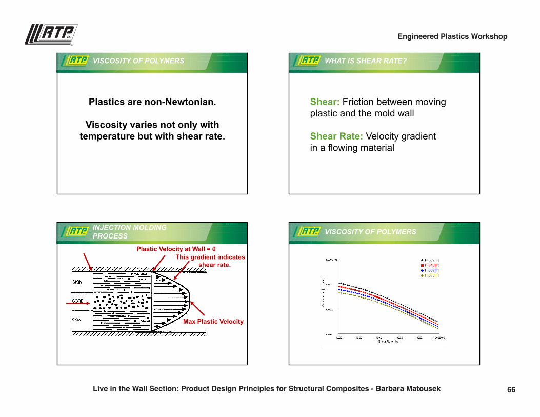
VISCOSITY OF POLYMERS
Plastics are non-Newtonian.
Viscosity varies not only with temperature but with shear rate.
WHAT IS SHEAR RATE?
Shear: Friction between moving plastic and the mold wall
Shear Rate: Velocity gradientin a flowing material
INJECTION MOLDING PROCESS
Plastic Velocity at Wall = 0
Max Plastic Velocity
This gradient indicatesshear rate.
VISCOSITY OF POLYMERS
66Live in the Wall Section: Product Design Principles for Structural Composites - Barbara Matousek
Engineered Plastics Workshop
9/28/2016
6
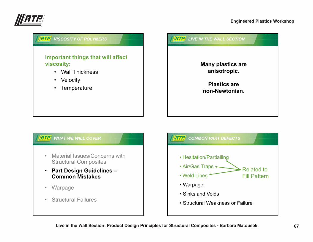
VISCOSITY OF POLYMERS
Important things that will affect viscosity:
• Wall Thickness• Velocity• Temperature
LIVE IN THE WALL SECTION
Many plastics are anisotropic.
Plastics are non-Newtonian.
WHAT WE WILL COVER
• Material Issues/Concerns with Structural Composites
• Part Design Guidelines –Common Mistakes
• Warpage
• Structural Failures
• Hesitation/Partialling
• Air/Gas Traps
• Weld Lines
• Warpage
• Sinks and Voids
• Structural Weakness or Failure
COMMON PART DEFECTS
Related toFill Pattern
67Live in the Wall Section: Product Design Principles for Structural Composites - Barbara Matousek
Engineered Plastics Workshop
9/28/2016
7
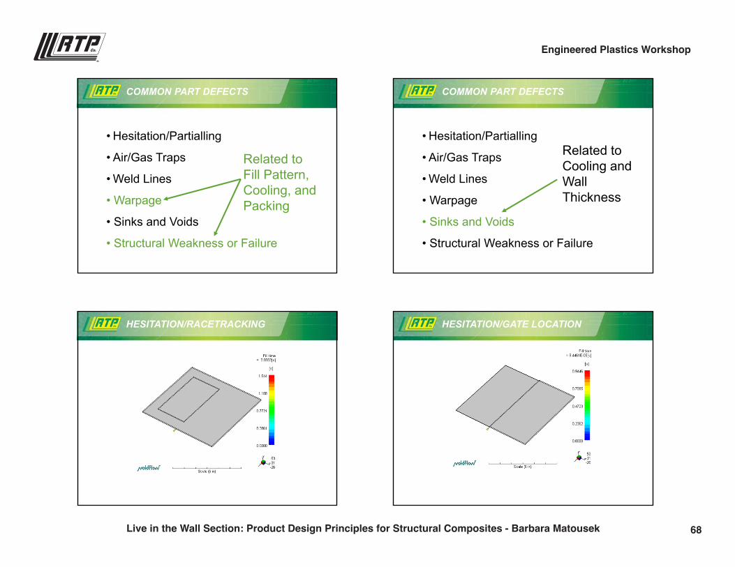
• Hesitation/Partialling
• Air/Gas Traps
• Weld Lines
• Warpage
• Sinks and Voids
• Structural Weakness or Failure
COMMON PART DEFECTS
Related toFill Pattern,Cooling, andPacking
• Hesitation/Partialling
• Air/Gas Traps
• Weld Lines
• Warpage
• Sinks and Voids
• Structural Weakness or Failure
COMMON PART DEFECTS
Related toCooling andWallThickness
HESITATION/RACETRACKING
“Thin”
“Thick”
HESITATION/GATE LOCATION
“Thin”
“Thick”
68Live in the Wall Section: Product Design Principles for Structural Composites - Barbara Matousek
Engineered Plastics Workshop
9/28/2016
8
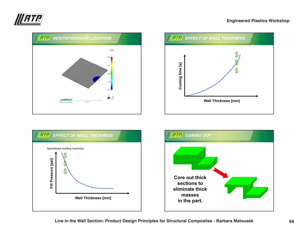
HESITATION/GATE LOCATION
“Thin”
“Thick”
EFFECT OF WALL THICKNESS
Coo
ling
time
[s]
Wall Thickness [mm]
$$$
Fill
Pres
sure
[psi
]
Wall Thickness [mm]
Specialized molding machines
$$$
EFFECT OF WALL THICKNESS CORING OUT
Core out thick sections to
eliminate thick masses
in the part.
69Live in the Wall Section: Product Design Principles for Structural Composites - Barbara Matousek
Engineered Plastics Workshop
9/28/2016
9
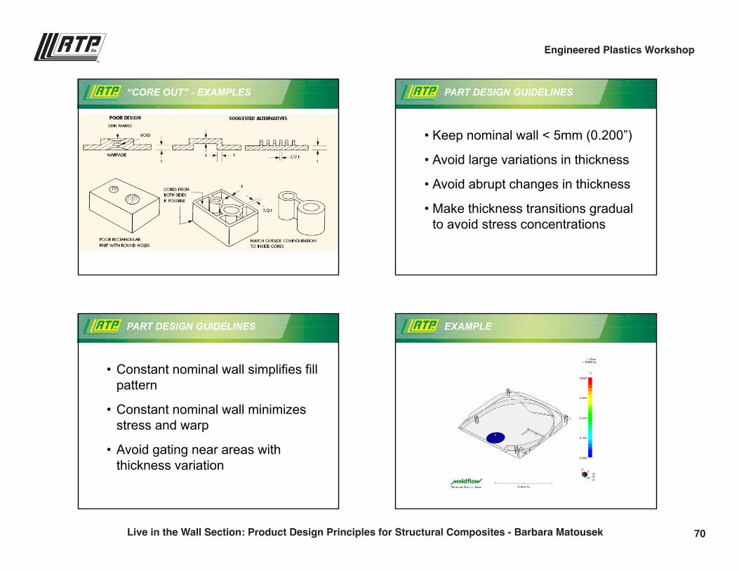
“CORE OUT” - EXAMPLES PART DESIGN GUIDELINES
• Keep nominal wall < 5mm (0.200”)
• Avoid large variations in thickness
• Avoid abrupt changes in thickness
• Make thickness transitions gradual to avoid stress concentrations
PART DESIGN GUIDELINES
• Constant nominal wall simplifies fill pattern
• Constant nominal wall minimizes stress and warp
• Avoid gating near areas with thickness variation
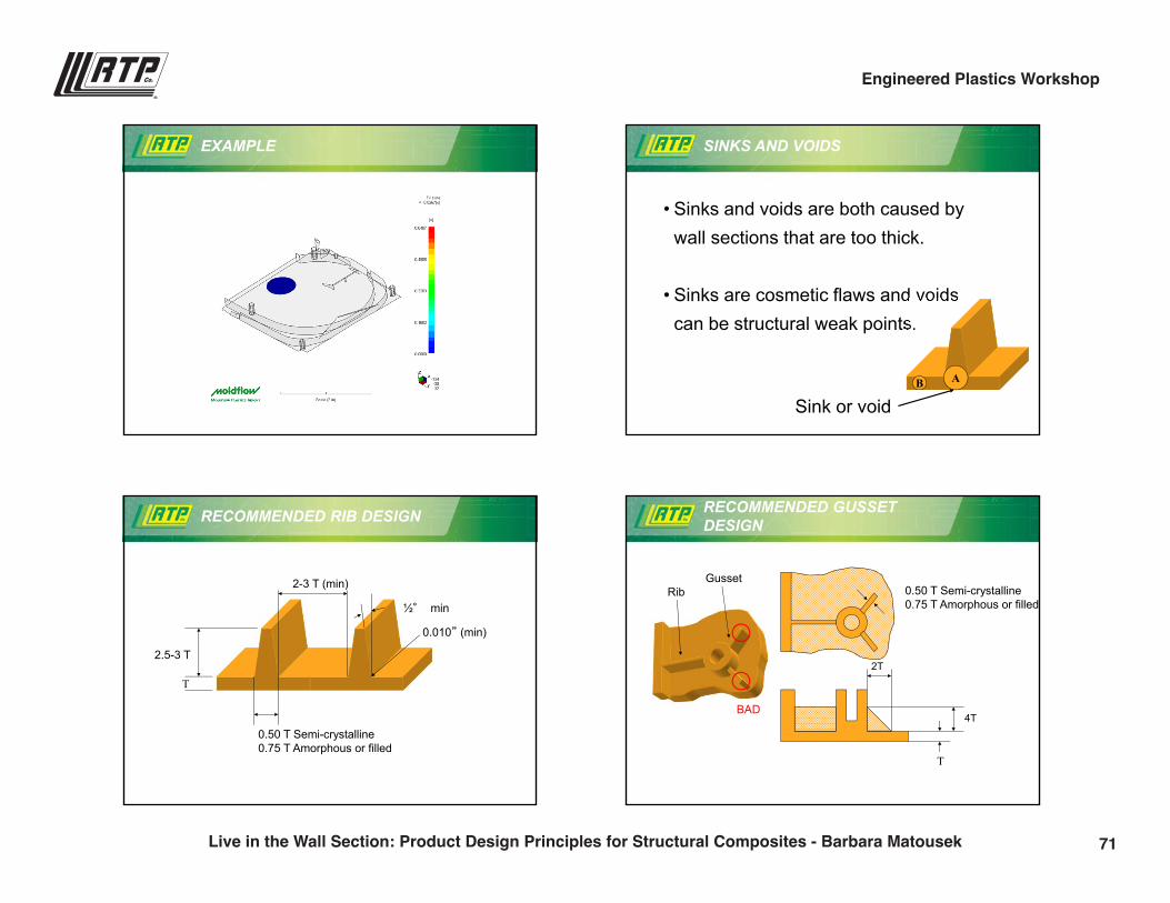
EXAMPLE
70Live in the Wall Section: Product Design Principles for Structural Composites - Barbara Matousek
Engineered Plastics Workshop
9/28/2016
10
EXAMPLE
• Sinks and voids are both caused by wall sections that are too thick.
• Sinks are cosmetic flaws and voids can be structural weak points.
AB
Sink or void
SINKS AND VOIDS
RECOMMENDED RIB DESIGN
T
2.5-3 T
½° min
2-3 T (min)
0.50 T Semi-crystalline0.75 T Amorphous or filled
0.010” (min)
RECOMMENDED GUSSET DESIGN
T
4T
2T
GussetRib
BAD
0.50 T Semi-crystalline0.75 T Amorphous or filled
71Live in the Wall Section: Product Design Principles for Structural Composites - Barbara Matousek
Engineered Plastics Workshop
9/28/2016
11
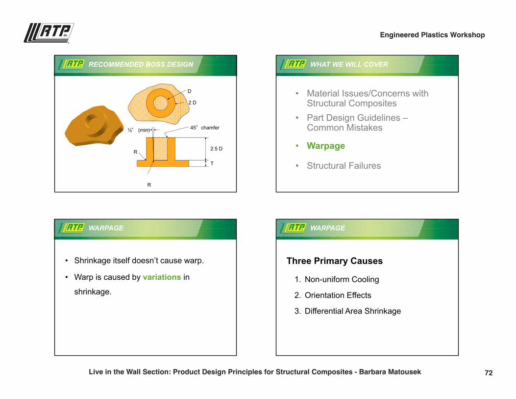
RECOMMENDED BOSS DESIGN
T
D
2 D
2.5 D
R
R
45°chamfer½° (min)
WHAT WE WILL COVER
• Material Issues/Concerns with Structural Composites
• Part Design Guidelines –Common Mistakes
• Warpage
• Structural Failures
WARPAGE
• Shrinkage itself doesn’t cause warp.
• Warp is caused by variations in
shrinkage.
WARPAGE
Three Primary Causes
1. Non-uniform Cooling
2. Orientation Effects
3. Differential Area Shrinkage
72Live in the Wall Section: Product Design Principles for Structural Composites - Barbara Matousek
Engineered Plastics Workshop
9/28/2016
12
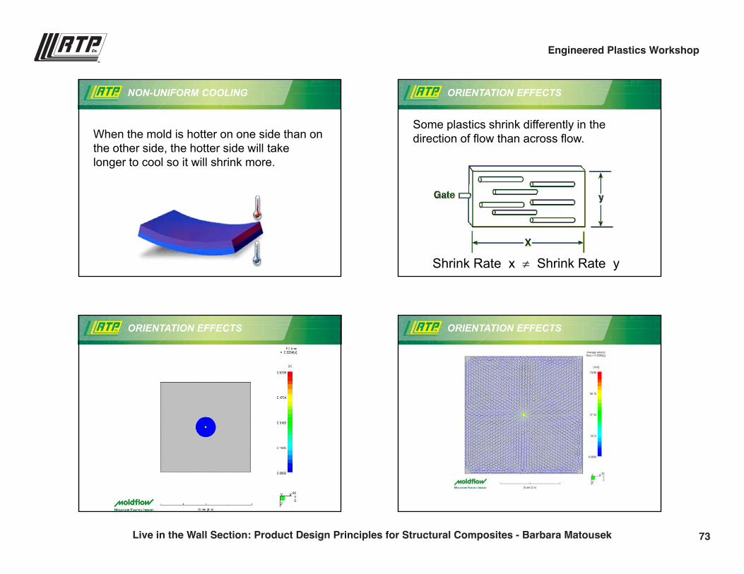
NON-UNIFORM COOLING
When the mold is hotter on one side than on the other side, the hotter side will take longer to cool so it will shrink more.
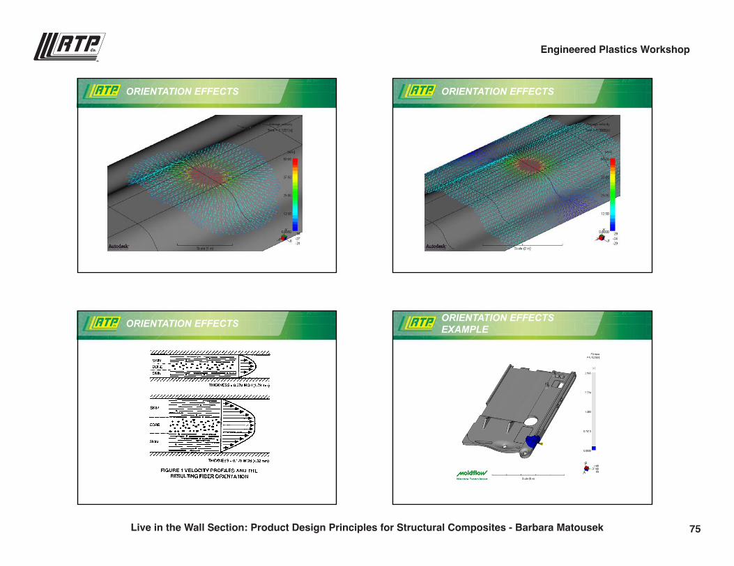
ORIENTATION EFFECTS
Some plastics shrink differently in the direction of flow than across flow.
Shrink Rate x Shrink Rate y
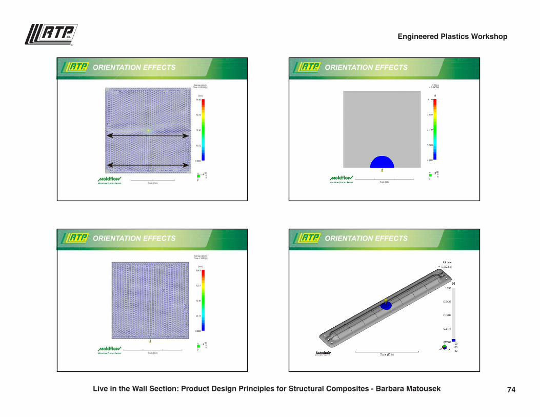
ORIENTATION EFFECTS ORIENTATION EFFECTS
73Live in the Wall Section: Product Design Principles for Structural Composites - Barbara Matousek
Engineered Plastics Workshop
9/28/2016
13
ORIENTATION EFFECTS ORIENTATION EFFECTS
ORIENTATION EFFECTS ORIENTATION EFFECTS
74Live in the Wall Section: Product Design Principles for Structural Composites - Barbara Matousek
Engineered Plastics Workshop
9/28/2016
14
ORIENTATION EFFECTS ORIENTATION EFFECTS
ORIENTATION EFFECTS ORIENTATION EFFECTS EXAMPLE
75Live in the Wall Section: Product Design Principles for Structural Composites - Barbara Matousek
Engineered Plastics Workshop
9/28/2016
15
ORIENTATION EFFECTS EXAMPLE
ORIENTATION EFFECTS EXAMPLE
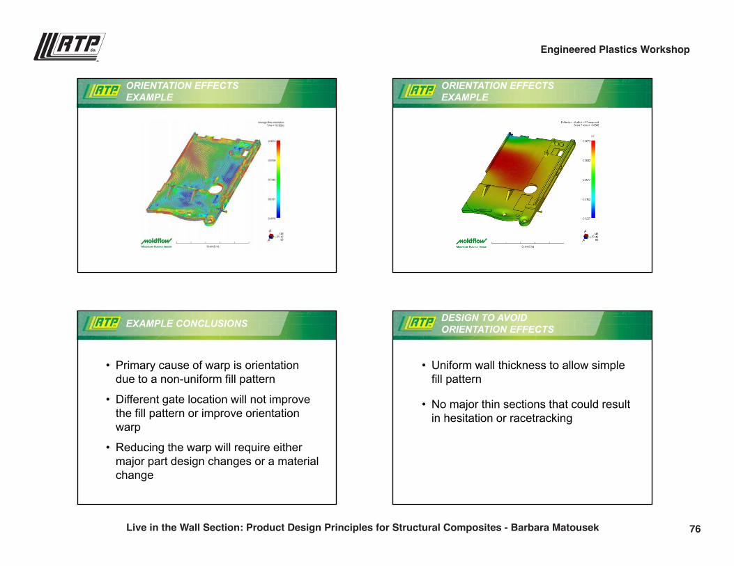
EXAMPLE CONCLUSIONS
• Primary cause of warp is orientation due to a non-uniform fill pattern
• Different gate location will not improve the fill pattern or improve orientation warp
• Reducing the warp will require either major part design changes or a material change
DESIGN TO AVOID ORIENTATION EFFECTS
• Uniform wall thickness to allow simple fill pattern
• No major thin sections that could result in hesitation or racetracking
76Live in the Wall Section: Product Design Principles for Structural Composites - Barbara Matousek
Engineered Plastics Workshop
9/28/2016
16
REDUCING ORIENTATION EFFECTS
• Gate for the most uniform flow
• Adjust molding conditions (often higher temps and faster injections will help)
• Adjust wall thickness
• Use more uniformly shrinking material (or sometimes a lower viscosity material)
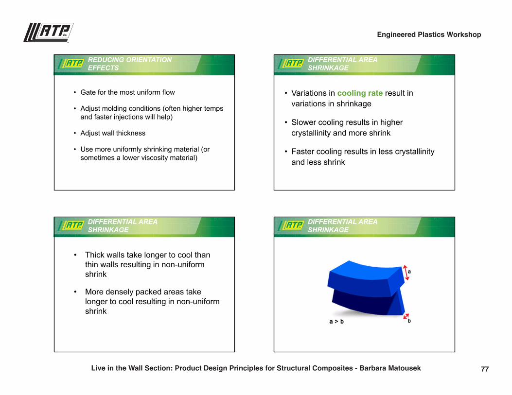
DIFFERENTIAL AREA SHRINKAGE
• Variations in cooling rate result in variations in shrinkage
• Slower cooling results in higher crystallinity and more shrink
• Faster cooling results in less crystallinityand less shrink
DIFFERENTIAL AREA SHRINKAGE
• Thick walls take longer to cool than thin walls resulting in non-uniform shrink
• More densely packed areas take longer to cool resulting in non-uniform shrink
DIFFERENTIAL AREA SHRINKAGE
77Live in the Wall Section: Product Design Principles for Structural Composites - Barbara Matousek
Engineered Plastics Workshop
9/28/2016
17
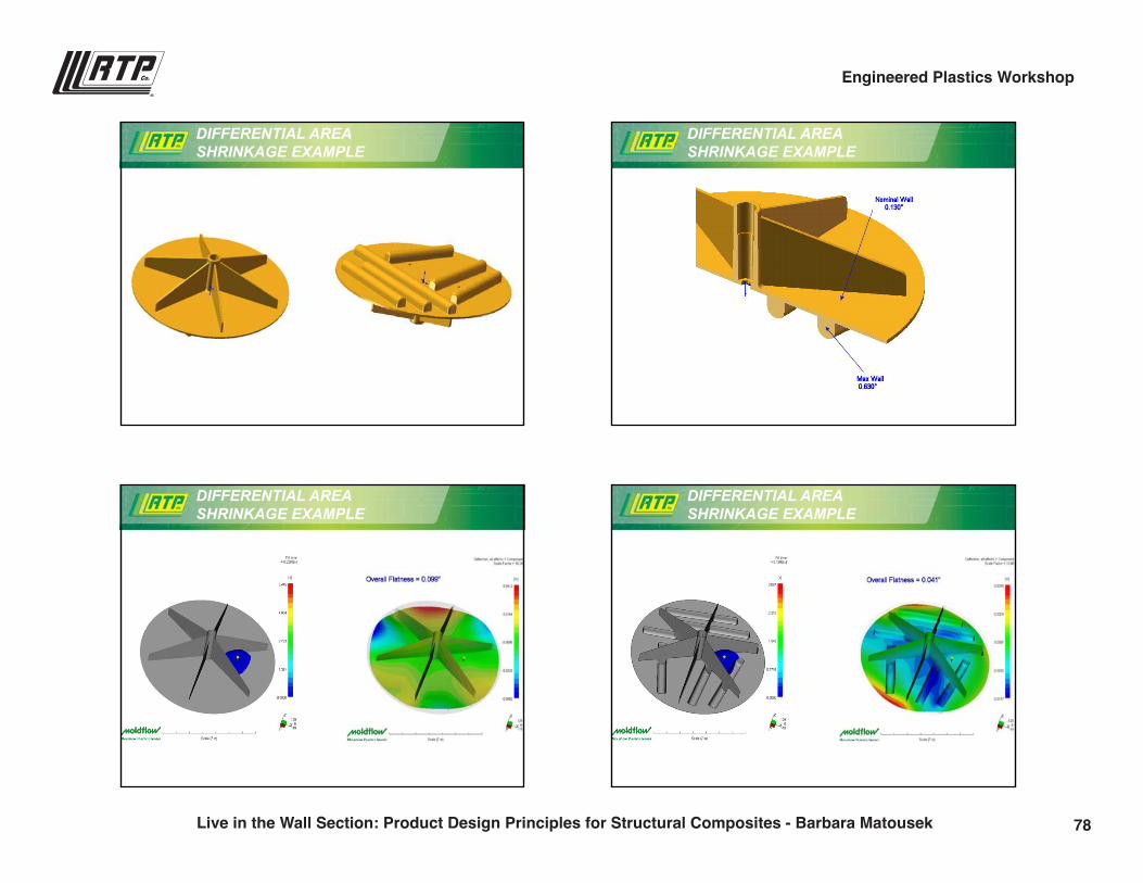
DIFFERENTIAL AREA SHRINKAGE EXAMPLE
DIFFERENTIAL AREA SHRINKAGE EXAMPLE
DIFFERENTIAL AREA SHRINKAGE EXAMPLE
DIFFERENTIAL AREA SHRINKAGE EXAMPLE
78Live in the Wall Section: Product Design Principles for Structural Composites - Barbara Matousek
Engineered Plastics Workshop
9/28/2016
18
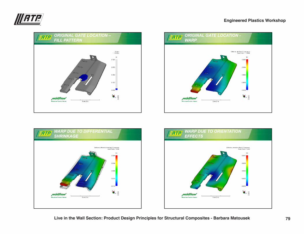
ORIGINAL GATE LOCATION –FILL PATTERN
ORIGINAL GATE LOCATION -WARP
WARP DUE TO DIFFERENTIAL SHRINKAGE
WARP DUE TO ORIENTATION EFFECTS
79Live in the Wall Section: Product Design Principles for Structural Composites - Barbara Matousek
Engineered Plastics Workshop
9/28/2016
19
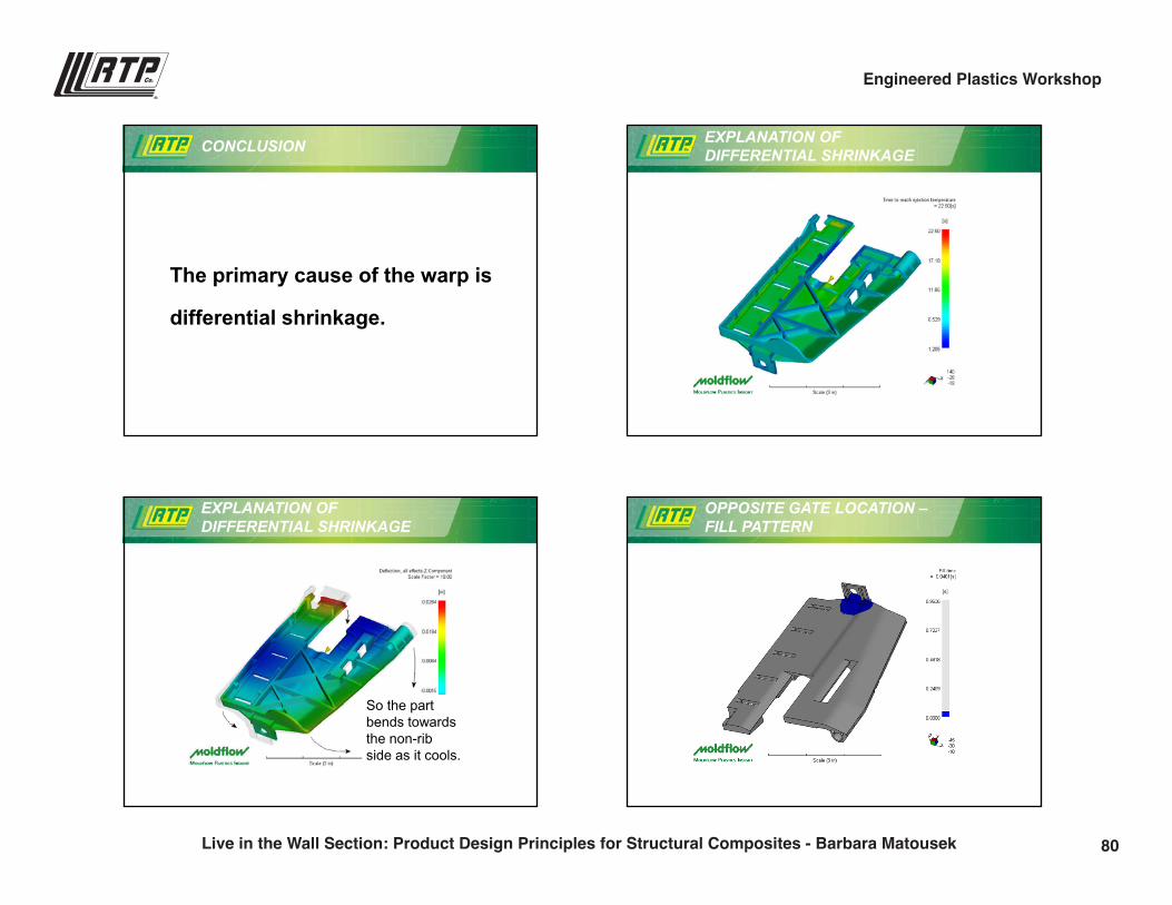
CONCLUSION
The primary cause of the warp is
differential shrinkage.
EXPLANATION OF DIFFERENTIAL SHRINKAGE
EXPLANATION OF DIFFERENTIAL SHRINKAGE
So the part bends towards the non-ribside as it cools.
OPPOSITE GATE LOCATION –FILL PATTERN
80Live in the Wall Section: Product Design Principles for Structural Composites - Barbara Matousek
Engineered Plastics Workshop
9/28/2016
20
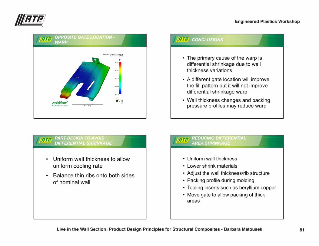
OPPOSITE GATE LOCATION -WARP CONCLUSIONS
• The primary cause of the warp is differential shrinkage due to wall thickness variations
• A different gate location will improve the fill pattern but it will not improve differential shrinkage warp
• Wall thickness changes and packing pressure profiles may reduce warp
PART DESIGN TO AVOID DIFFERENTIAL SHRINKAGE
• Uniform wall thickness to allow uniform cooling rate
• Balance thin ribs onto both sides of nominal wall
REDUCING DIFFERENTIAL AREA SHRINKAGE
• Uniform wall thickness• Lower shrink materials• Adjust the wall thickness/rib structure• Packing profile during molding• Tooling inserts such as beryllium copper• Move gate to allow packing of thick
areas
81Live in the Wall Section: Product Design Principles for Structural Composites - Barbara Matousek
Engineered Plastics Workshop
9/28/2016
21
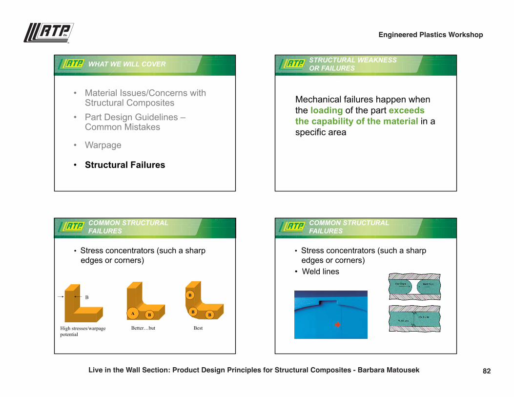
WHAT WE WILL COVER
• Material Issues/Concerns with Structural Composites
• Part Design Guidelines –Common Mistakes
• Warpage
• Structural Failures
STRUCTURAL WEAKNESS OR FAILURES
Mechanical failures happen when the loading of the part exceedsthe capability of the material in a specific area
• Stress concentrators (such a sharpedges or corners)
High stresses/warpage potential
Better…but
A BB
B
B
B
Best
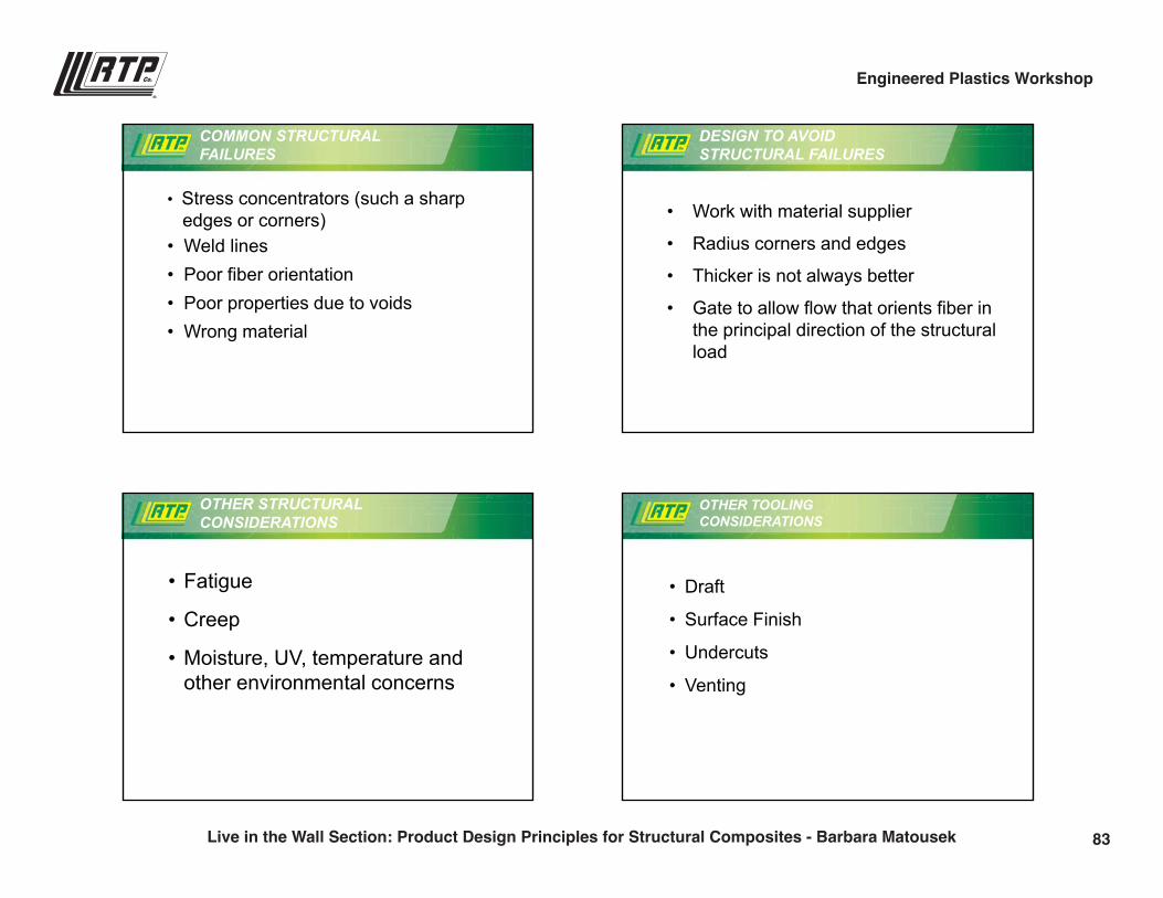
COMMON STRUCTURAL FAILURES
• Stress concentrators (such a sharpedges or corners)
• Weld lines
COMMON STRUCTURAL FAILURES
82Live in the Wall Section: Product Design Principles for Structural Composites - Barbara Matousek
Engineered Plastics Workshop
9/28/2016
22
• Stress concentrators (such a sharpedges or corners)
• Weld lines• Poor fiber orientation• Poor properties due to voids• Wrong material
COMMON STRUCTURAL FAILURES
DESIGN TO AVOID STRUCTURAL FAILURES
• Work with material supplier
• Radius corners and edges
• Thicker is not always better
• Gate to allow flow that orients fiber in the principal direction of the structural load
OTHER STRUCTURAL CONSIDERATIONS
• Fatigue
• Creep
• Moisture, UV, temperature and other environmental concerns
OTHER TOOLING CONSIDERATIONS
• Draft
• Surface Finish
• Undercuts
• Venting
83Live in the Wall Section: Product Design Principles for Structural Composites - Barbara Matousek
Engineered Plastics Workshop
9/28/2016
23
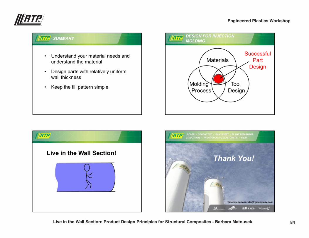
SUMMARY
• Understand your material needs and understand the material
• Design parts with relatively uniform wall thickness
• Keep the fill pattern simple
DESIGN FOR INJECTION MOLDING
Materials
Molding Process
Tool Design
SuccessfulPart
Design
Live in the Wall Section!
rtpcompany.com [email protected]
Thank You!
84Live in the Wall Section: Product Design Principles for Structural Composites - Barbara Matousek
Engineered Plastics Workshop
Taking Charge of Resistivity:An Introduction to Conductive Plastics Technology
Steve Maki | VP of [email protected](507) 474-5371
1:45 p.m.
85
1
RTP Company – Your Global Compounder of Custom Engineered Thermoplastics
rtpcompany.com [email protected]
Taking Charge of Resistivity: An Introduction to Conductive Plastics Technology
Steve MakiVice President Technology
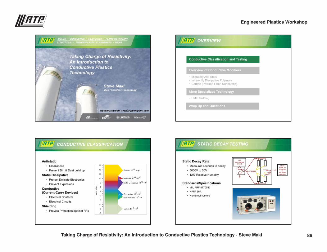
OVERVIEW
Conductive Classification and Testing
• Migratory Anti-Stats• Inherently Dissipative Polymers• Carbon (Powder, Fiber, Nanotubes)
Overview of Conductive Modifiers
• EMI Shielding
More Specialized Technology
Wrap Up and Questions
Antistatic• Cleanliness• Prevent Dirt & Dust build up
Static Dissipative• Protect Delicate Electronics• Prevent Explosions
Conductive (Current-Carry Devices)
• Electrical Contacts• Electrical Circuits
Shielding• Provide Protection against RFs
CONDUCTIVE CLASSIFICATION
Static Decay Rate• Measures seconds to decay• 5000V to 50V• 12% Relative Humidity
Standards/Specifications• MIL PRF 81705 D• NFPA 56A• Numerous Others
STATIC DECAY TESTING
DECAY SIGNAL TO INDICATING
OR RECORDINGEQUIPMENT
5‐k V HIGH‐VOLTAGE
SOURCE
ELECTRODESTEST
SAMPLE
86Taking Charge of Resistivity: An Introduction to Conductive Plastics Technology - Steve Maki
Engineered Plastics Workshop
2
RTP Company – Your Global Compounder of Custom Engineered Thermoplastics
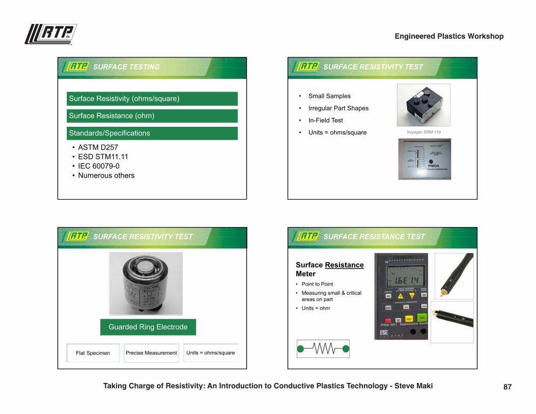
SURFACE TESTING
Surface Resistivity (ohms/square)
Surface Resistance (ohm)
Standards/Specifications
• ASTM D257• ESD STM11.11• IEC 60079-0• Numerous others
• Small Samples
• Irregular Part Shapes
• In-Field Test
• Units = ohms/square
SURFACE RESISTIVITY TEST
Voyager SRM-110
SURFACE RESISTIVITY TEST
Flat Specimen Precise Measurement Units = ohms/square
Guarded Ring Electrode
SURFACE RESISTANCE TEST
Surface Resistance Meter• Point to Point
• Measuring small & critical areas on part
• Units = ohm
87Taking Charge of Resistivity: An Introduction to Conductive Plastics Technology - Steve Maki
Engineered Plastics Workshop
3
RTP Company – Your Global Compounder of Custom Engineered Thermoplastics
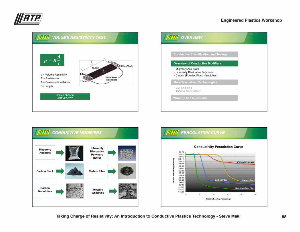
VOLUME RESISTIVITY TEST
�
A
ρ = Volume ResistivityR = ResistanceA = Cross-sectional Area� = Length
� � ���
Units = ohm-cmASTM D-257
OVERVIEW
Conductive Classification and Testing
• Migratory Anti-Stats• Inherently Dissipative Polymers• Carbon (Powder, Fiber, Nanotubes)
Overview of Conductive Modifiers
• EMI Shielding• Thermal Conductivity
More Specialized Technologies
Wrap Up and Questions
CONDUCTIVE MODIFIERS
Inherently Dissipative Polymers
(IDPs)
Carbon Black
Migratory Antistats
Carbon Fiber
Metallic Additives
Carbon Nanotubes
PERCOLATION CURVE
88Taking Charge of Resistivity: An Introduction to Conductive Plastics Technology - Steve Maki
Engineered Plastics Workshop
4
RTP Company – Your Global Compounder of Custom Engineered Thermoplastics
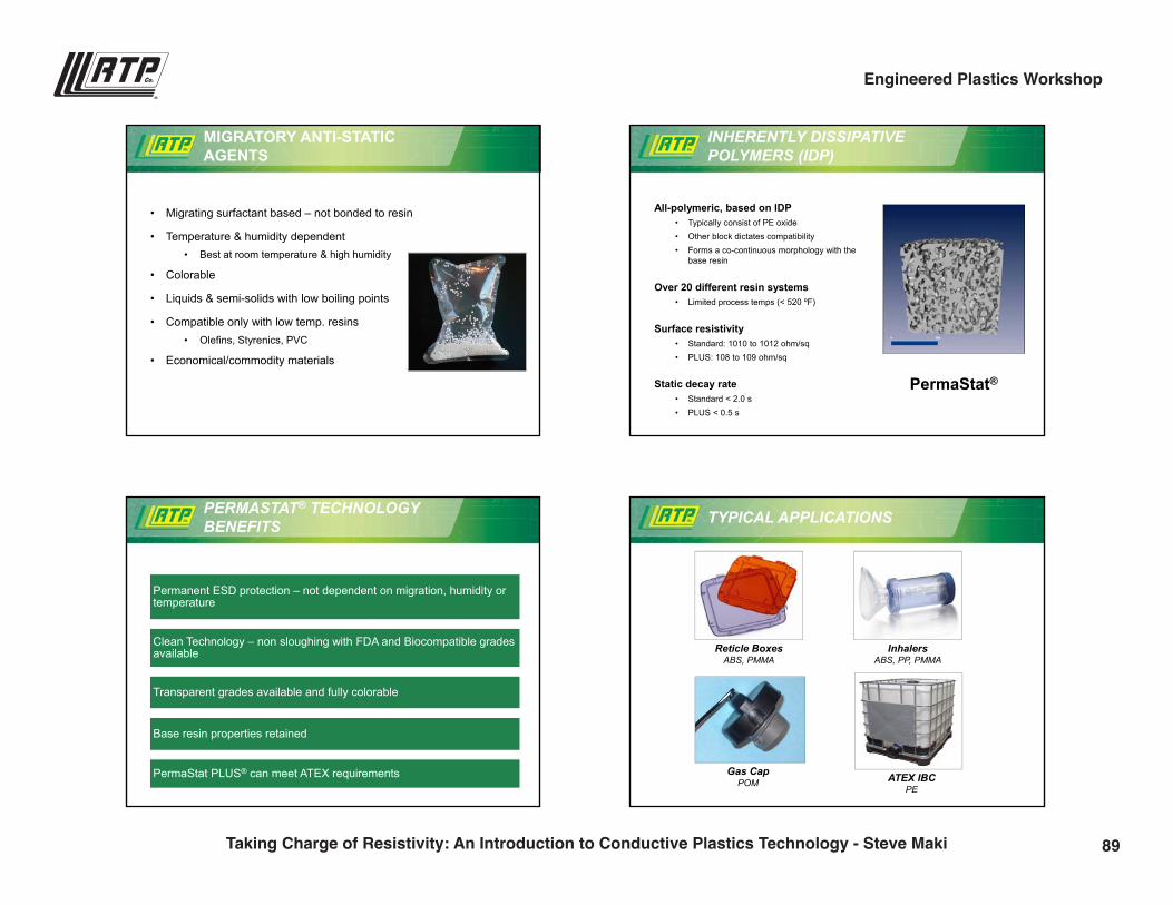
MIGRATORY ANTI-STATIC AGENTS
• Migrating surfactant based – not bonded to resin
• Temperature & humidity dependent• Best at room temperature & high humidity
• Colorable
• Liquids & semi-solids with low boiling points
• Compatible only with low temp. resins• Olefins, Styrenics, PVC
• Economical/commodity materials
INHERENTLY DISSIPATIVE POLYMERS (IDP)
All-polymeric, based on IDP• Typically consist of PE oxide• Other block dictates compatibility • Forms a co-continuous morphology with the
base resin
Over 20 different resin systems• Limited process temps (< 520 ºF)
Surface resistivity• Standard: 1010 to 1012 ohm/sq• PLUS: 108 to 109 ohm/sq
Static decay rate• Standard < 2.0 s• PLUS < 0.5 s
PermaStat®
PERMASTAT® TECHNOLOGY BENEFITS
Permanent ESD protection – not dependent on migration, humidity or temperature
Clean Technology – non sloughing with FDA and Biocompatible grades available
Transparent grades available and fully colorable
Base resin properties retained
PermaStat PLUS® can meet ATEX requirements
TYPICAL APPLICATIONS
Reticle BoxesABS, PMMA
InhalersABS, PP, PMMA
Gas CapPOM ATEX IBC
PE
89Taking Charge of Resistivity: An Introduction to Conductive Plastics Technology - Steve Maki
Engineered Plastics Workshop
5
RTP Company – Your Global Compounder of Custom Engineered Thermoplastics
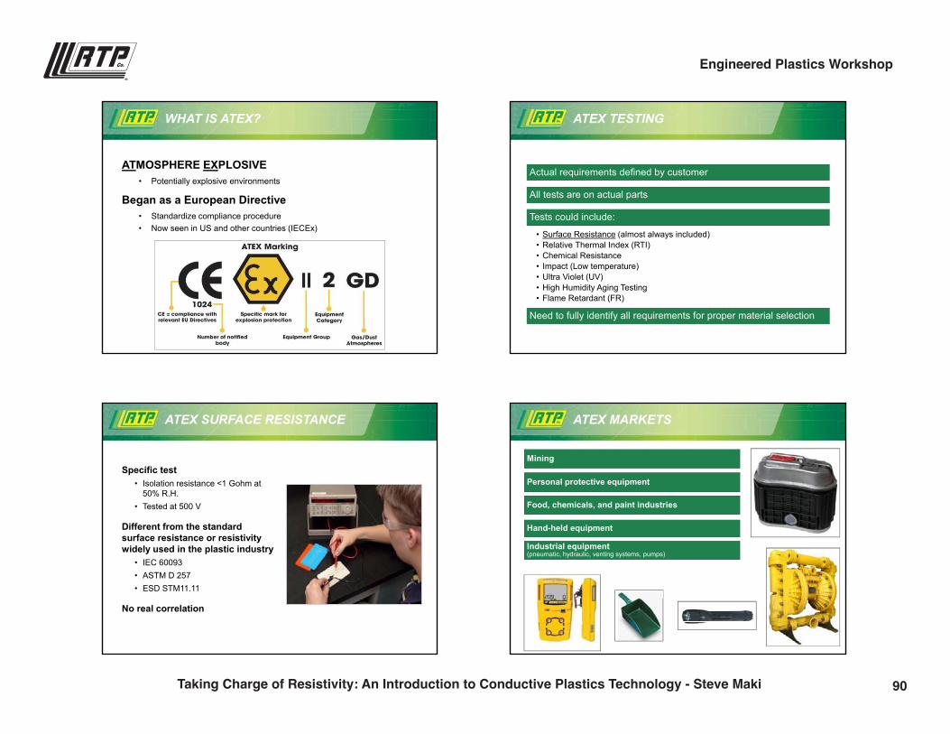
WHAT IS ATEX?
ATMOSPHERE EXPLOSIVE• Potentially explosive environments
Began as a European Directive• Standardize compliance procedure• Now seen in US and other countries (IECEx)
ATEX TESTING
Actual requirements defined by customer
All tests are on actual parts
Tests could include:
• Surface Resistance (almost always included)• Relative Thermal Index (RTI)• Chemical Resistance• Impact (Low temperature)• Ultra Violet (UV)• High Humidity Aging Testing• Flame Retardant (FR)
Need to fully identify all requirements for proper material selection
Specific test• Isolation resistance <1 Gohm at
50% R.H.• Tested at 500 V
Different from the standard surface resistance or resistivity widely used in the plastic industry
• IEC 60093• ASTM D 257• ESD STM11.11
No real correlation
ATEX SURFACE RESISTANCE ATEX MARKETS
Mining
Personal protective equipment
Food, chemicals, and paint industries
Hand-held equipment
Industrial equipment (pneumatic, hydraulic, venting systems, pumps)
90Taking Charge of Resistivity: An Introduction to Conductive Plastics Technology - Steve Maki
Engineered Plastics Workshop
6
RTP Company – Your Global Compounder of Custom Engineered Thermoplastics
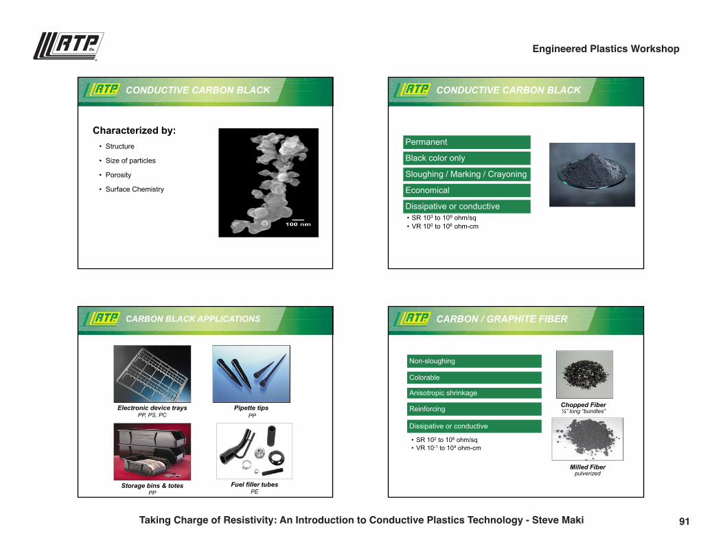
Characterized by:• Structure
• Size of particles
• Porosity
• Surface Chemistry
CONDUCTIVE CARBON BLACK CONDUCTIVE CARBON BLACK
Permanent
Black color only
Sloughing / Marking / Crayoning
Economical
Dissipative or conductive• SR 103 to 109 ohm/sq• VR 100 to 106 ohm-cm
CARBON BLACK APPLICATIONS
Pipette tipsPP
Electronic device traysPP, PS, PC
Storage bins & totesPP
Fuel filler tubesPE
CARBON / GRAPHITE FIBER
Chopped Fiber ¼” long “bundles”
Milled Fiber pulverized
Non-sloughing
Colorable
Anisotropic shrinkage
Reinforcing
Dissipative or conductive
• SR 102 to 106 ohm/sq• VR 10-1 to 104 ohm-cm
91Taking Charge of Resistivity: An Introduction to Conductive Plastics Technology - Steve Maki
Engineered Plastics Workshop
7
RTP Company – Your Global Compounder of Custom Engineered Thermoplastics
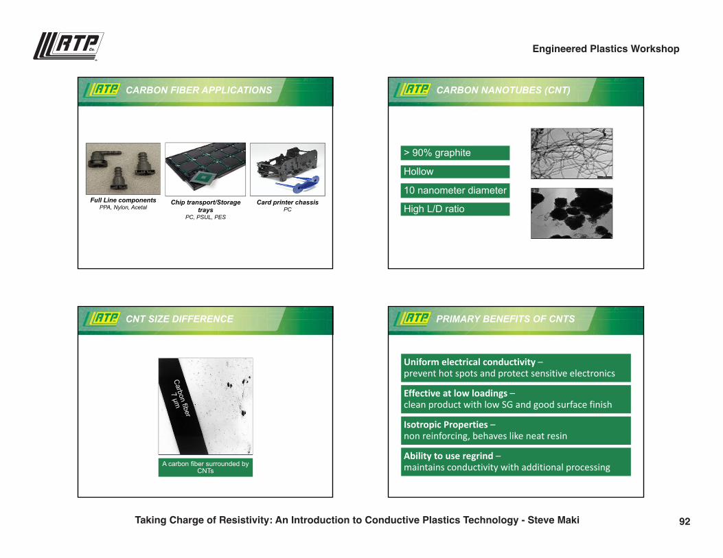
CARBON FIBER APPLICATIONS
Datacard Group, Minnetonka, MN
Full Line componentsPPA, Nylon, Acetal
Chip transport/Storage trays
PC, PSUL, PES
Card printer chassis PC
> 90% graphite
Hollow
10 nanometer diameter
High L/D ratio
CARBON NANOTUBES (CNT)
CNT SIZE DIFFERENCE
A carbon fiber surrounded by CNTs
PRIMARY BENEFITS OF CNTS
Uniform electrical conductivity –prevent hot spots and protect sensitive electronics
Effective at low loadings –clean product with low SG and good surface finish
Isotropic Properties –non reinforcing, behaves like neat resin
Ability to use regrind –maintains conductivity with additional processing
92Taking Charge of Resistivity: An Introduction to Conductive Plastics Technology - Steve Maki
Engineered Plastics Workshop
8
RTP Company – Your Global Compounder of Custom Engineered Thermoplastics
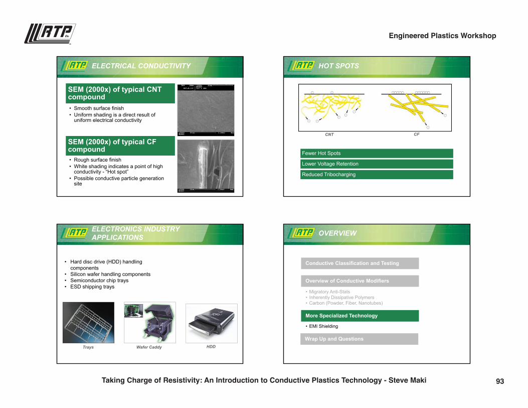
ELECTRICAL CONDUCTIVITY
SEM (2000x) of typical CNT compound• Smooth surface finish• Uniform shading is a direct result of
uniform electrical conductivity
SEM (2000x) of typical CF compound• Rough surface finish• White shading indicates a point of high
conductivity - “Hot spot”• Possible conductive particle generation
site
HOT SPOTS
CNT CF
Fewer Hot Spots
Lower Voltage Retention
Reduced Tribocharging
ELECTRONICS INDUSTRY APPLICATIONS
Trays Wafer Caddy HDD
• Hard disc drive (HDD) handling components
• Silicon wafer handling components• Semiconductor chip trays• ESD shipping trays
Conductive Classification and Testing
• Migratory Anti-Stats• Inherently Dissipative Polymers• Carbon (Powder, Fiber, Nanotubes)
Overview of Conductive Modifiers
• EMI Shielding
More Specialized Technology
Wrap Up and Questions
OVERVIEW
93Taking Charge of Resistivity: An Introduction to Conductive Plastics Technology - Steve Maki
Engineered Plastics Workshop
9
RTP Company – Your Global Compounder of Custom Engineered Thermoplastics
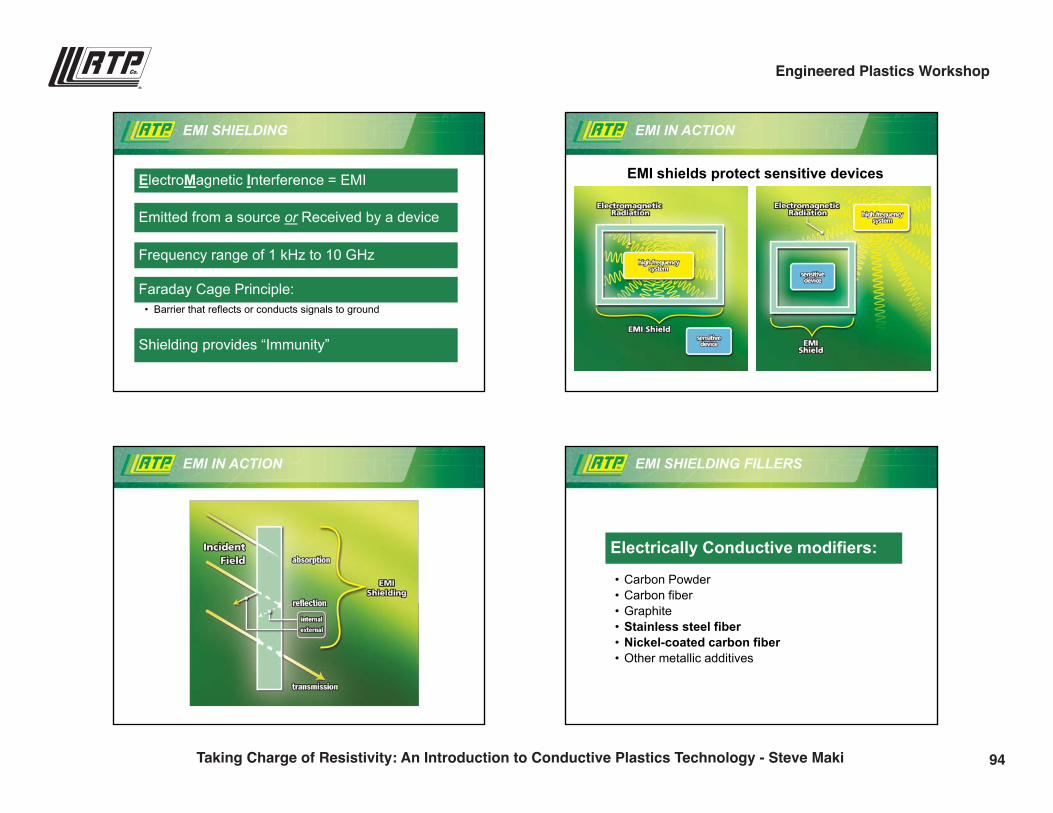
ElectroMagnetic Interference = EMI
Emitted from a source or Received by a device
Frequency range of 1 kHz to 10 GHz
Faraday Cage Principle:• Barrier that reflects or conducts signals to ground
Shielding provides “Immunity”
EMI SHIELDING EMI IN ACTION
EMI shields protect sensitive devices
EMI IN ACTION EMI SHIELDING FILLERS
Electrically Conductive modifiers:
• Carbon Powder• Carbon fiber• Graphite• Stainless steel fiber• Nickel-coated carbon fiber• Other metallic additives
94Taking Charge of Resistivity: An Introduction to Conductive Plastics Technology - Steve Maki
Engineered Plastics Workshop
10
RTP Company – Your Global Compounder of Custom Engineered Thermoplastics
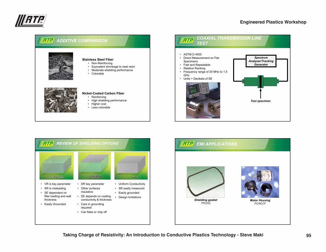
ADDITIVE COMPARISON
Stainless Steel Fiber• Non-Reinforcing• Equivalent shrinkage to neat resin• Moderate shielding performance• Colorable
Nickel-Coated Carbon Fiber• Reinforcing• High shielding performance• Higher cost• Less colorable
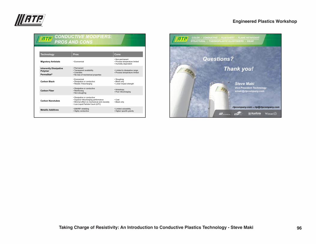
COAXIAL TRANSMISSION LINE TEST
SpectrumAnalyzer/Tracking
Generator
Test specimen
• ASTM D 4935• Direct Measurement on Flat
Specimens• Fast and Repeatable• Relative Ranking• Frequency range of 30 MHz to 1.5
GHz• Units = Decibels of SE
REVIEW OF SHIELDING OPTIONS
• VR is key parameter• SR is misleading• SE dependent on
filler loading and wall thickness
• Easily Grounded
• SR key parameter• Other surfaces
insulative• SE depends on coating
conductivity & thickness• Care in grounding
required• Can flake or chip off
• Uniform Conductivity• SR easily measured• Easily grounded• Design limitations
EMI APPLICATIONS
Shielding gasketTPO/SS
Motor Housing PC/NCCF
95Taking Charge of Resistivity: An Introduction to Conductive Plastics Technology - Steve Maki
Engineered Plastics Workshop
11
RTP Company – Your Global Compounder of Custom Engineered Thermoplastics
CONDUCTIVE MODIFIERS: PROS AND CONS
Technology Pros Cons
Migratory Antistats • Economical• Non-permanent• Process temperature limited• Humidity dependent
Inherently Dissipative PolymerPermaStat®
• Permanent• Transparent availability• Colorable• No loss of mechanical properties
• Limited to dissipative range• Process temperature limited
Carbon Black• Economical• Dissipative or conductive• Resists Tribocharging
• Sloughing• Black only• Lower impact strength
Carbon Fiber• Dissipative or conductive• Reinforcing• Non-sloughing
• Anisotropy• Poor tribocharging
Carbon Nanotubes• Dissipative or conductive• Superior tribocharging performance• Minimal effect on mechanical and viscosity• Low Liquid Particle Count (LPC)
• Cost• Black only
Metallic Additives • EMI/RFI shielding• Highly conductive
• Limited colorability• Higher specific gravity
rtpcompany.com [email protected]
Steve MakiVice President [email protected]
Questions?
Thank you!
96Taking Charge of Resistivity: An Introduction to Conductive Plastics Technology - Steve Maki
Engineered Plastics Workshop
Wear in the World of Plastics
Ben Gerjets | Product Development [email protected](507) 474-5381
2:30 p.m.
97
9/28/2016
1
rtpcompany.com [email protected]
Wear in the World of Plastics
Ben GerjetsProduct Development EngineerWear and Friction Products
WEAR AND FRICTION
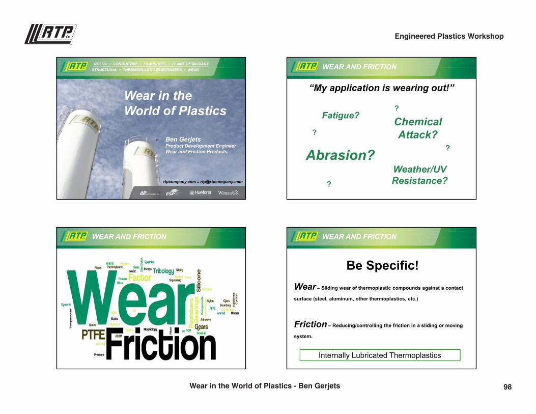
“My application is wearing out!”
ChemicalAttack?
Weather/UV Resistance?
Abrasion?
Fatigue??
?
?
?
WEAR AND FRICTION WEAR AND FRICTION
Be Specific!Wear – Sliding wear of thermoplastic compounds against a contact
surface (steel, aluminum, other thermoplastics, etc.)
Friction – Reducing/controlling the friction in a sliding or moving
system.
Internally Lubricated Thermoplastics
98Wear in the World of Plastics - Ben Gerjets
Engineered Plastics Workshop
9/28/2016
2
AGENDA
I. Wear Definitions & Test Methods
II. Friction Definitions & Test Methods
III. Additive Technologies
IV. Application Examples
V. Extreme Conditions – Ultra Wear
WEAR DEFINITIONS
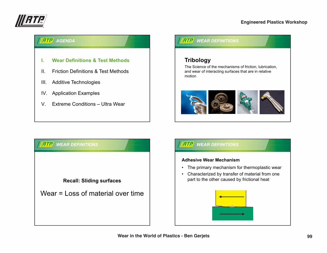
TribologyThe Science of the mechanisms of friction, lubrication, and wear of interacting surfaces that are in relative motion
WEAR DEFINITIONS
Recall: Sliding surfaces
Wear = Loss of material over time
WEAR DEFINITIONS
Adhesive Wear Mechanism• The primary mechanism for thermoplastic wear• Characterized by transfer of material from one
part to the other caused by frictional heat
99Wear in the World of Plastics - Ben Gerjets
Engineered Plastics Workshop
9/28/2016
3
WEAR DEFINITIONS
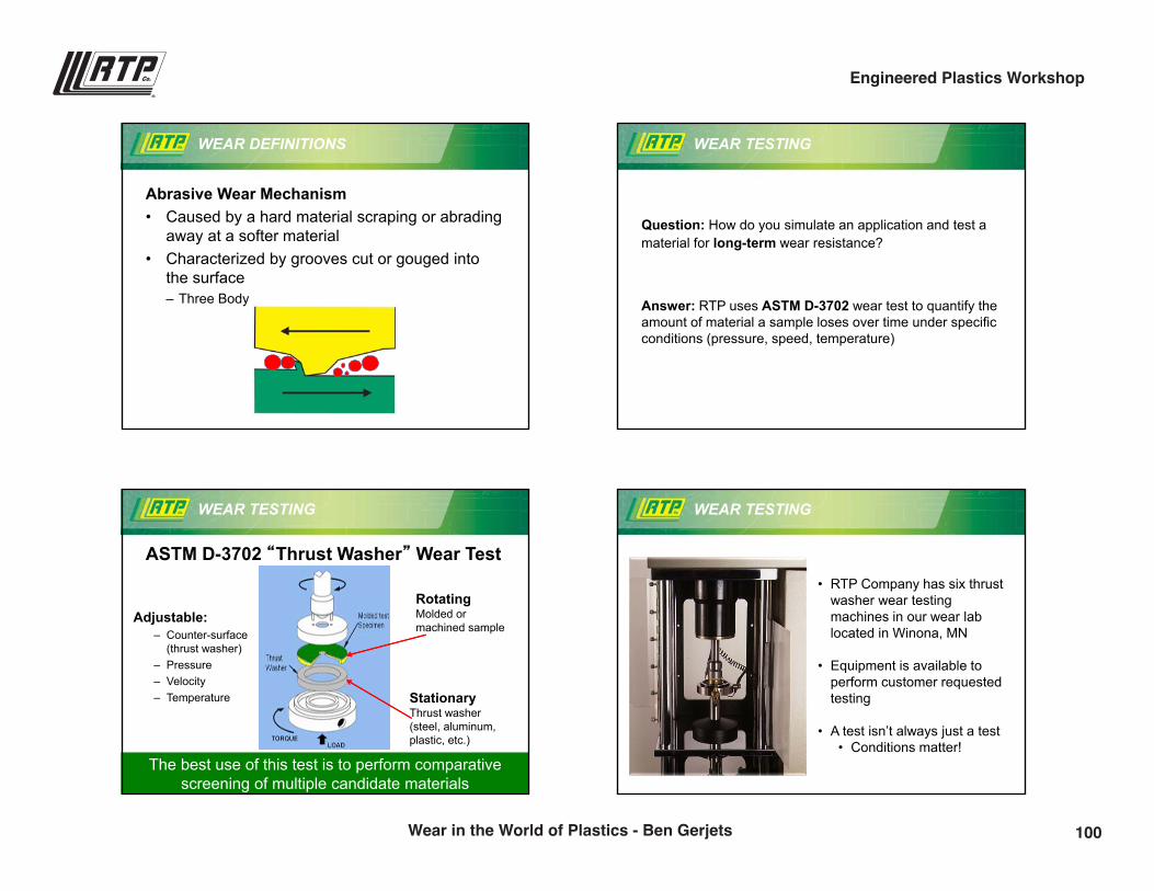
Abrasive Wear Mechanism• Caused by a hard material scraping or abrading
away at a softer material• Characterized by grooves cut or gouged into
the surface– Three Body
WEAR TESTING
Question: How do you simulate an application and test a material for long-term wear resistance?
Answer: RTP uses ASTM D-3702 wear test to quantify the amount of material a sample loses over time under specific conditions (pressure, speed, temperature)
WEAR TESTING
ASTM D-3702 “Thrust Washer” Wear Test
RotatingMolded or machined sample
StationaryThrust washer(steel, aluminum, plastic, etc.)
Adjustable:– Counter-surface
(thrust washer)– Pressure– Velocity– Temperature
The best use of this test is to perform comparative screening of multiple candidate materials
WEAR TESTING
• RTP Company has six thrust washer wear testing machines in our wear lab located in Winona, MN
• Equipment is available to perform customer requested testing
• A test isn’t always just a test• Conditions matter!
100Wear in the World of Plastics - Ben Gerjets
Engineered Plastics Workshop
9/28/2016
4
WEAR TESTING
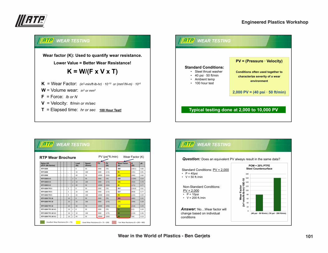
Wear factor (K): Used to quantify wear resistance.
Lower Value = Better Wear Resistance!
K = W/(F x V x T)
K = Wear Factor: (in3-min/ft-lb-hr) · 10-10 or (mm3/N-m) · 10-8
W = Volume wear: in3 or mm3
F = Force: lb or N
V = Velocity: ft/min or m/sec
T = Elapsed time: hr or sec 100 Hour Test!
WEAR TESTING
Standard Conditions:• Steel thrust washer• 40 psi · 50 ft/min • Ambient temp• 100 hour test
PV = (Pressure · Velocity)
Conditions often used together to characterize severity of a wear
environment
2,000 PV = (40 psi · 50 ft/min)
Typical testing done at 2,000 to 10,000 PV
WEAR TESTING
Nylon 6/6 (RTP 200 Series)
Load(lb)
Speed(ft/min)
PV PV(SI)
Wear Factor(K)
K(SI)
µk
RTP 0200 - - - - - 8 50 2000 (70) 400 (1811) 0.66
RTP 0200 - - - - - 10 100 5000 (175) 95 (191) 0.91
RTP 0200 - - - - - 40 50 10000 (350) 191 (384) 0.60
RTP 0200 SI 2 - - - - 2 8 50 2000 (70) 639 (1284) 0.54
RTP 0200 SI 2 - - - - 2 10 100 5000 (175) 181 (364) 0.78
RTP 0200 SI 2 - - - - 2 40 50 10000 (350) 85 (171) 0.77
RTP 0200 TFE 5 - - - 5 - 8 50 2000 (70) 957 (1924) 0.61
RTP 0200 TFE 5 - - - 5 - 10 100 5000 (175) 427 (858) 0.77
RTP 0200 TFE 5 - - - 5 - 20 100 10000 (350) 76 (153) 0.59
RTP 0200 TFE 10 - - - 10 - 8 50 2000 (70) 341 (685) 0.31
RTP 0200 TFE 10 - - - 10 - 10 100 5000 (175) 171 (344) 0.28
RTP 0200 TFE 10 - - - 10 - 40 50 10000 (350) 156 (314) 0.29
RTP 0200 TFE 18 SI 2 - - - 18 2 8 50 2000 (70) 11 (22) 0.20
RTP 0200 TFE 18 SI 2 - - - 18 2 10 100 5000 (175) 59 (119) 0.36
RTP 0200 TFE 18 SI 2 - - - 18 2 40 50 10000 (350) 18 (36) 0.19
Wear Factor (K)PV (psi*ft./min)RTP Wear Brochure
- Excellent Wear Resistance (K= < 75) - Good Wear Resistance (K = 75 – 200) - Fair Wear Resistance (K = 200 – 400)
WEAR TESTING
Question: Does an equivalent PV always result in the same data?
Non-Standard Conditions: PV = 2,000• P = 10psi• V = 200 ft./min
Standard Conditions: PV = 2,000• P = 40psi• V = 50 ft./min
0
20
40
60
80
100
120
140
160
180
(40 psi · 50 ft/min) (10 psi · 200 ft/min)
Wea
r Fac
tor
(in3 -
min
/ft-lb
-hr)
·10E
-10
POM + 20% PTFESteel Countersurface
Answer: No…Wear factor will change based on individual conditions
101Wear in the World of Plastics - Ben Gerjets
Engineered Plastics Workshop
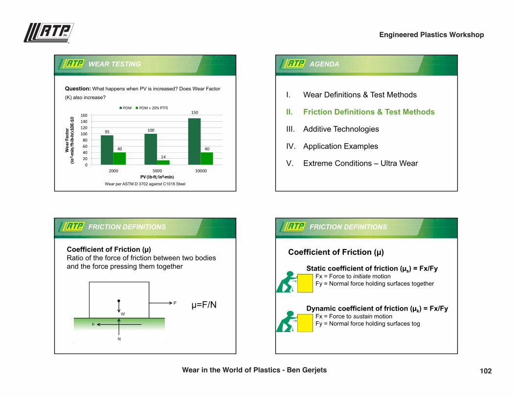
9/28/2016
5
WEAR TESTING
Question: What happens when PV is increased? Does Wear Factor
(K) also increase?
95 100
150
40
14
40
020406080
100120140160
2000 5000 10000
Wea
r Fac
tor
(in3 -m
in/f
t-lb-
hr)·1
0E-1
0
PV (lb-ft/in2-min)
POM POM + 20% PTFE
Wear per ASTM D 3702 against C1018 Steel
AGENDA
I. Wear Definitions & Test Methods
II. Friction Definitions & Test Methods
III. Additive Technologies
IV. Application Examples
V. Extreme Conditions – Ultra Wear
FRICTION DEFINITIONS
Coefficient of Friction (µ)Ratio of the force of friction between two bodies and the force pressing them together
µ=F/N
FRICTION DEFINITIONS
Coefficient of Friction (µ)
Static coefficient of friction (µs) = Fx/FyFx = Force to initiate motionFy = Normal force holding surfaces together
Dynamic coefficient of friction (µk) = Fx/FyFx = Force to sustain motionFy = Normal force holding surfaces tog
102Wear in the World of Plastics - Ben Gerjets
Engineered Plastics Workshop
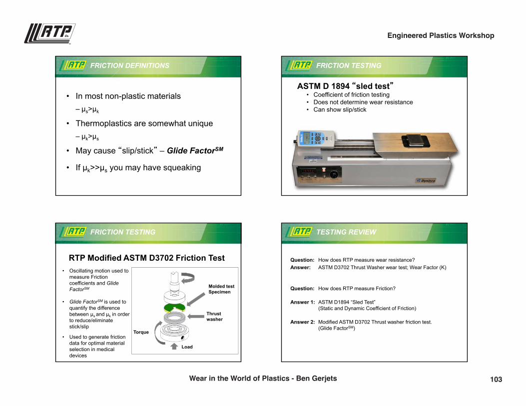
9/28/2016
6
FRICTION DEFINITIONS
• In most non-plastic materials– µs>µk
• Thermoplastics are somewhat unique– µk>µs
• May cause “slip/stick” – Glide FactorSM
• If µk>>µs you may have squeaking
FRICTION TESTING
ASTM D 1894 “sled test”• Coefficient of friction testing• Does not determine wear resistance• Can show slip/stick
FRICTION TESTING
RTP Modified ASTM D3702 Friction Test• Oscillating motion used to
measure Friction coefficients and GlideFactorSM
• Glide FactorSM is used to quantify the difference between µs and µk in order to reduce/eliminate stick/slip
• Used to generate friction data for optimal material selection in medical devices
Molded test Specimen
Thrust washer
Torque
Load
TESTING REVIEW
Question: How does RTP measure wear resistance? Answer: ASTM D3702 Thrust Washer wear test; Wear Factor (K)
Question: How does RTP measure Friction?
Answer 1: ASTM D1894 “Sled Test” (Static and Dynamic Coefficient of Friction)
Answer 2: Modified ASTM D3702 Thrust washer friction test. (Glide FactorSM)
103Wear in the World of Plastics - Ben Gerjets
Engineered Plastics Workshop
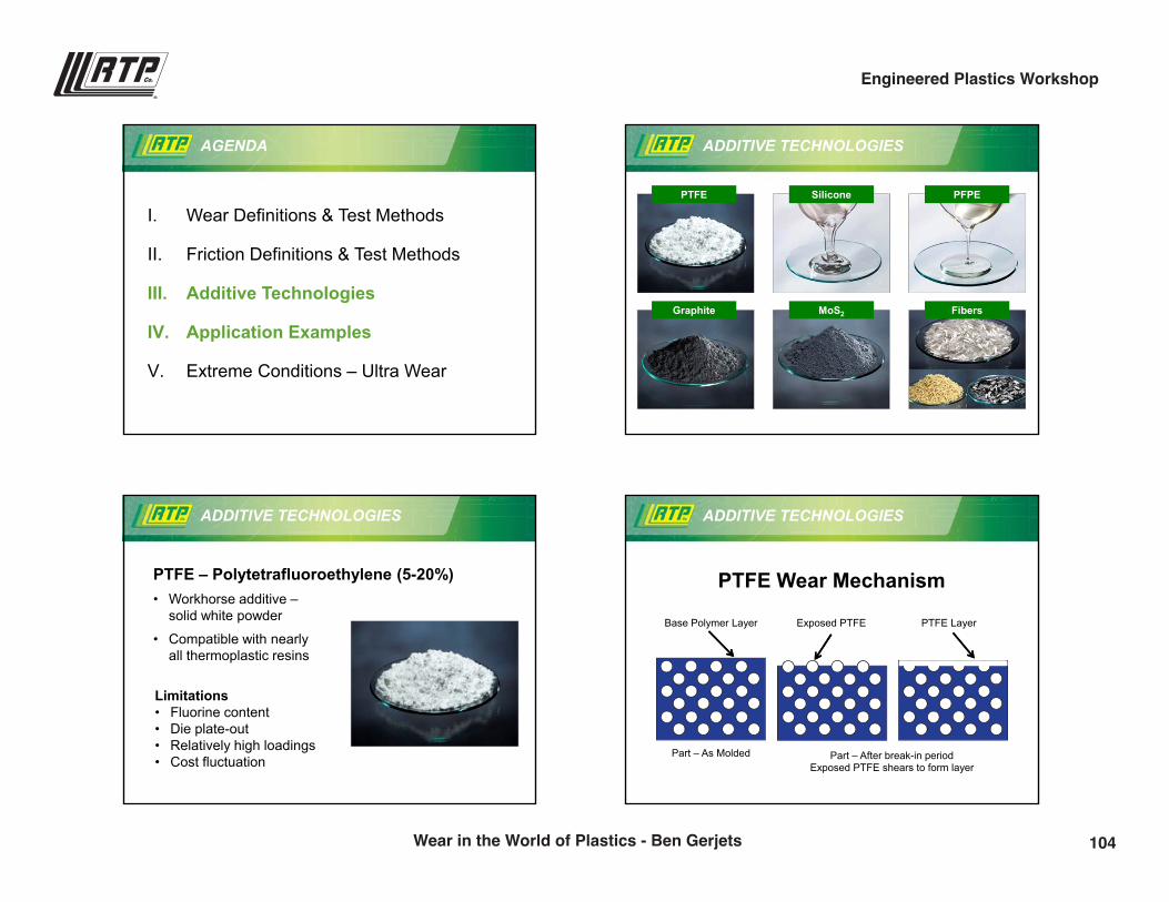
9/28/2016
7
AGENDA
I. Wear Definitions & Test Methods
II. Friction Definitions & Test Methods
III. Additive Technologies
IV. Application Examples
V. Extreme Conditions – Ultra Wear
ADDITIVE TECHNOLOGIES
PTFE Silicone PFPE
Graphite MoS2 Fibers
ADDITIVE TECHNOLOGIES
PTFE – Polytetrafluoroethylene (5-20%)• Workhorse additive –
solid white powder
• Compatible with nearly all thermoplastic resins
Limitations• Fluorine content• Die plate-out• Relatively high loadings• Cost fluctuation
ADDITIVE TECHNOLOGIES
PTFE Wear Mechanism
Base Polymer Layer Exposed PTFE PTFE Layer
Part – As Molded Part – After break-in periodExposed PTFE shears to form layer
104Wear in the World of Plastics - Ben Gerjets
Engineered Plastics Workshop
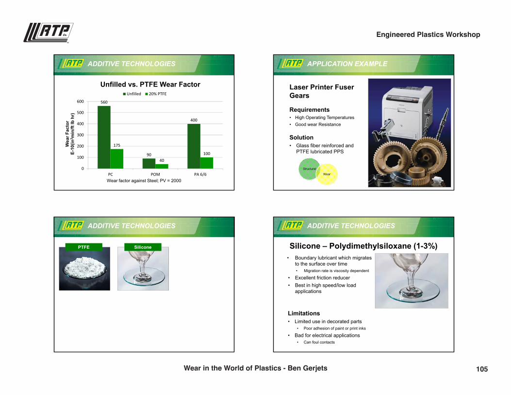
9/28/2016
8
ADDITIVE TECHNOLOGIES
560
90
400
175
40100
0
100
200
300
400
500
600
PC POM PA 6/6
Wea
r Fac
tor
E-10
(in3 m
in/ft
lb h
r)
Unfilled 20% PTFE
Wear factor against Steel; PV = 2000
Unfilled vs. PTFE Wear Factor
APPLICATION EXAMPLE
Laser Printer Fuser Gears
Requirements• High Operating Temperatures• Good wear Resistance
Solution• Glass fiber reinforced and
PTFE lubricated PPS
Structural
Wear
ADDITIVE TECHNOLOGIES
PTFE Silicone
ADDITIVE TECHNOLOGIES
Silicone – Polydimethylsiloxane (1-3%)
Limitations• Limited use in decorated parts
• Poor adhesion of paint or print inks
• Bad for electrical applications• Can foul contacts
• Boundary lubricant which migrates to the surface over time • Migration rate is viscosity dependent
• Excellent friction reducer• Best in high speed/low load
applications
105Wear in the World of Plastics - Ben Gerjets
Engineered Plastics Workshop
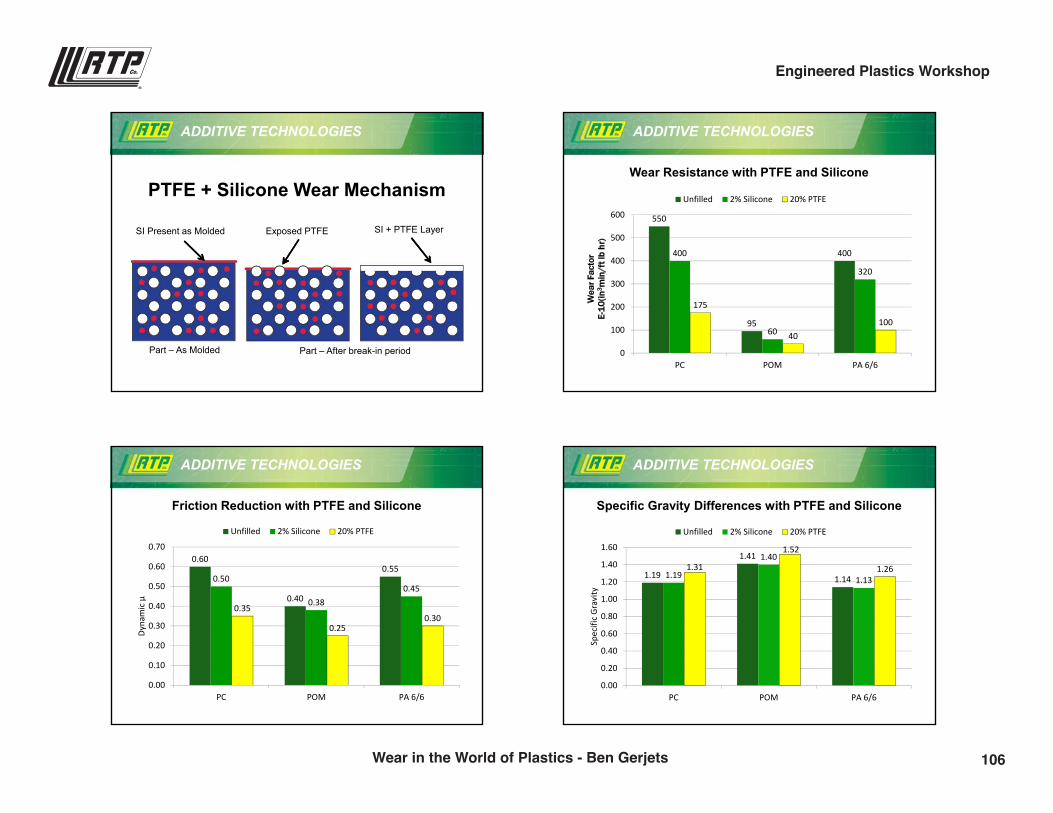
9/28/2016
9
ADDITIVE TECHNOLOGIES
PTFE + Silicone Wear Mechanism
SI Present as Molded Exposed PTFE SI + PTFE Layer
Part – As Molded Part – After break-in period
ADDITIVE TECHNOLOGIES
550
95
400400
60
320
175
40100
0
100
200
300
400
500
600
PC POM PA 6/6
Wea
r Fac
tor
E-10
(in3 m
in/f
t lb
hr)
Unfilled 2% Silicone 20% PTFE
Wear Resistance with PTFE and Silicone
ADDITIVE TECHNOLOGIES
0.60
0.40
0.550.50
0.380.45
0.35
0.250.30
0.00
0.10
0.20
0.30
0.40
0.50
0.60
0.70
PC POM PA 6/6
Dyna
mic
µ
Unfilled 2% Silicone 20% PTFE
Friction Reduction with PTFE and Silicone
ADDITIVE TECHNOLOGIES
1.19
1.41
1.141.19
1.40
1.131.31
1.52
1.26
0.00
0.20
0.40
0.60
0.80
1.00
1.20
1.40
1.60
PC POM PA 6/6
Spec
ific
Grav
ity
Unfilled 2% Silicone 20% PTFE
Specific Gravity Differences with PTFE and Silicone
106Wear in the World of Plastics - Ben Gerjets
Engineered Plastics Workshop
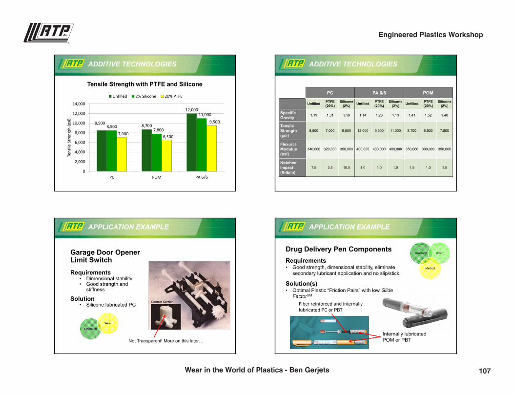
9/28/2016
10
ADDITIVE TECHNOLOGIES
8,500 8,700
12,000
8,5007,800
11,000
7,000 6,500
9,500
0
2,000
4,000
6,000
8,000
10,000
12,000
14,000
PC POM PA 6/6
Tens
ile S
tren
gth
(psi)
Unfilled 2% Silicone 20% PTFE
Tensile Strength with PTFE and Silicone
ADDITIVE TECHNOLOGIES
PC PA 6/6 POM
Unfilled PTFE (20%)
Silicone(2%) Unfilled PTFE
(20%)Silicone
(2%) Unfilled PTFE (20%)
Silicone (2%)
SpecificGravity 1.19 1.31 1.19 1.14 1.26 1.13 1.41 1.52 1.40
TensileStrength(psi)
8,500 7,000 8,500 12,000 9,500 11,000 8,700 6,500 7,800
Flexural Modulus(psi)
340,000 320,000 350,000 400,000 400,000 400,000 350,000 300,000 350,000
NotchedImpact(ft-lb/in)
7.5 3.5 10.5 1.0 1.0 1.0 1.5 1.0 1.5
APPLICATION EXAMPLE
Garage Door Opener Limit SwitchRequirements
• Dimensional stability• Good strength and
stiffness
Solution• Silicone lubricated PC
Structural
Wear
Not Transparent! More on this later…
Structural Wear
Medical
APPLICATION EXAMPLE
Drug Delivery Pen ComponentsRequirements• Good strength, dimensional stability, eliminate
secondary lubricant application and no slip/stick.
Solution(s)• Optimal Plastic “Friction Pairs” with low Glide
FactorSM
Internally lubricated POM or PBT
Fiber reinforced and internally lubricated PC or PBT
107Wear in the World of Plastics - Ben Gerjets
Engineered Plastics Workshop
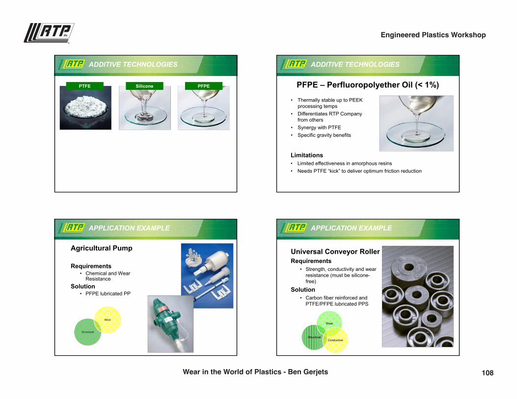
9/28/2016
11
ADDITIVE TECHNOLOGIES
PTFE Silicone PFPE
ADDITIVE TECHNOLOGIES
PFPE – Perfluoropolyether Oil (< 1%)
• Thermally stable up to PEEK processing temps
• Differentiates RTP Company from others
• Synergy with PTFE• Specific gravity benefits
Limitations• Limited effectiveness in amorphous resins• Needs PTFE “kick” to deliver optimum friction reduction
APPLICATION EXAMPLE
Agricultural Pump
Requirements• Chemical and Wear
ResistanceSolution
• PFPE lubricated PP
Structural
Wear
APPLICATION EXAMPLE
Universal Conveyor RollerRequirements
• Strength, conductivity and wear resistance (must be silicone-free)
Solution• Carbon fiber reinforced and
PTFE/PFPE lubricated PPS
Structural
Wear
Conductive
108Wear in the World of Plastics - Ben Gerjets
Engineered Plastics Workshop
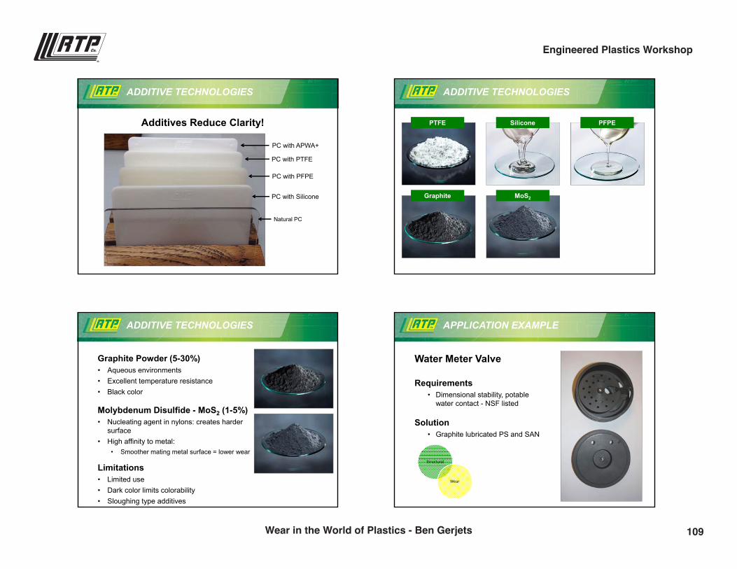
9/28/2016
12
ADDITIVE TECHNOLOGIES
Additives Reduce Clarity!
Natural PC
PC with APWA+
PC with PTFE
PC with PFPE
PC with Silicone
ADDITIVE TECHNOLOGIES
PTFE Silicone PFPE
Graphite MoS2
ADDITIVE TECHNOLOGIES
Graphite Powder (5-30%)• Aqueous environments• Excellent temperature resistance• Black color
Molybdenum Disulfide - MoS2 (1-5%)• Nucleating agent in nylons: creates harder
surface• High affinity to metal:
• Smoother mating metal surface = lower wear
Limitations• Limited use• Dark color limits colorability• Sloughing type additives
APPLICATION EXAMPLE
Water Meter Valve
Requirements• Dimensional stability, potable
water contact - NSF listed
Solution• Graphite lubricated PS and SAN
Structural
Wear
109Wear in the World of Plastics - Ben Gerjets
Engineered Plastics Workshop
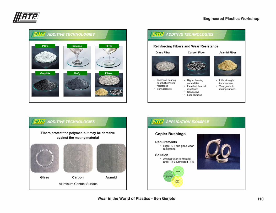
9/28/2016
13
ADDITIVE TECHNOLOGIES
PTFE Silicone PFPE
Graphite MoS2 Fibers
ADDITIVE TECHNOLOGIES
Reinforcing Fibers and Wear Resistance
Glass Fiber Carbon Fiber Aramid Fiber
• Improved bearing capabilities/wear resistance
• Very abrasive
• Higher bearing capabilities
• Excellent thermal resistance
• Conductive• Less abrasive
• Little strength improvement
• Very gentle to mating surface
ADDITIVE TECHNOLOGIES
Fibers protect the polymer, but may be abrasive against the mating material
Glass AramidCarbon
Aluminum Contact Surface
APPLICATION EXAMPLE
Copier Bushings
Requirements• High HDT and good wear
resistance
Solution• Aramid fiber reinforced
and PTFE lubricated PPA
Structural
Wear
HighTemp
110Wear in the World of Plastics - Ben Gerjets
Engineered Plastics Workshop
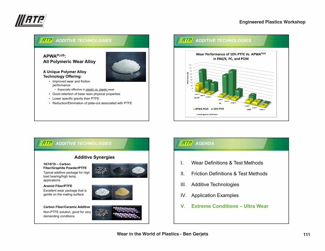
9/28/2016
14
ADDITIVE TECHNOLOGIES
APWAPLUS:All Polymeric Wear Alloy
A Unique Polymer Alloy Technology Offering:
• Improved wear and friction performance
• Especially effective in plastic vs. plastic wear• Good retention of base resin physical properties• Lower specific gravity than PTFE• Reduction/Elimination of plate-out associated with PTFE
ADDITIVE TECHNOLOGIES
ADDITIVE TECHNOLOGIES
Additive Synergies10/10/10 – Carbon Fiber/Graphite Powder/PTFETypical additive package for high load bearing/high temp. applications
Aramid Fiber/PTFEExcellent wear package that is gentle on the mating surface
Carbon Fiber/Ceramic AdditiveNon-PTFE solution, good for very demanding conditions
AGENDA
I. Wear Definitions & Test Methods
II. Friction Definitions & Test Methods
III. Additive Technologies
IV. Application Examples
V. Extreme Conditions – Ultra Wear
111Wear in the World of Plastics - Ben Gerjets
Engineered Plastics Workshop
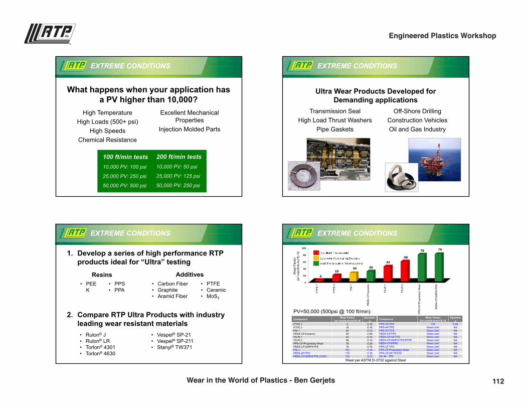
9/28/2016
15
EXTREME CONDITIONS
What happens when your application has a PV higher than 10,000?
High TemperatureHigh Loads (500+ psi)
High SpeedsChemical Resistance
Excellent Mechanical Properties
Injection Molded Parts
200 ft/min tests10,000 PV: 50 psi
25,000 PV: 125 psi
50,000 PV: 250 psi
100 ft/min tests10,000 PV: 100 psi
25,000 PV: 250 psi
50,000 PV: 500 psi
EXTREME CONDITIONS
Ultra Wear Products Developed for Demanding applications
Transmission SealHigh Load Thrust Washers
Pipe Gaskets
Off-Shore DrillingConstruction Vehicles Oil and Gas Industry
EXTREME CONDITIONS
1. Develop a series of high performance RTP products ideal for “Ultra” testing
• Carbon Fiber• Graphite• Aramid Fiber
• PTFE• Ceramic • MoS2
• PEEK
• PPS• PPA
2. Compare RTP Ultra Products with industry leading wear resistant materials
AdditivesResins
• Rulon® J• Rulon® LR• Torlon® 4301• Torlon® 4630
• Vespel® SP-21• Vespel® SP-211• Stanyl® TW371
EXTREME CONDITIONS
Not Melt Processable
Melt Processable Thermoplastic
Extensive Post Curing Process
0
20
40
60
80
100
PTFE
1
PTFE
2
PAI 1
PEEK
-CF/
Cer
amic
TS-P
I 1
TS-P
I 2
PPS-
CF/
Prop
rieta
ry W
ear
PEEK
-CF/
GR
PH/T
FE
4
1824 29
4358
78 79
Wea
r Fac
tor
(in3 -
min
/ft-lb
-hr)
*E-1
0
Compound Wear Factor(in3-min/ft-lb-hr)*E-10
Dynamicµ
PTFE 1 4 0.15PTFE 2 18 0.16PAI 1 24 0.12PEEK-CF/Ceramic 29 0.06TS-PI 1 43 0.14TS-PI 2 58 0.15PPS-CF/Proprietary Wear 78 0.24PEEK-CF/GRPH/TFE 79 0.16PAI 2 105 0.18PEEK-AF/TFE 119 0.18PEEK-CF/GRPH/TFE (CGP) 133 0.23
Compound Wear Factor(in3-min/ft-lb-hr)*E-10
Dynamicµ
PPS-CF/TFE 134 0.26PPS-AF/TFE Wear Limit NAPPS-GF/TFE Wear Limit NAPEEK-CF/TFE Wear Limit NAPEEK-CF/AF/TFE Wear Limit NAPEEK-CF/GRPH/TFE/PFPE Wear Limit NAPEEK-CF/PFPE Wear Limit NAPPA-CF/TFE Wear Limit NAPPA-CF/Proprietary Wear Wear Limit NAPPA-CF/AF/TFE/SI Wear Limit NAPA 46 - TFE Wear Limit NA
PV=50,000 (500psi @ 100 ft/min)
Wear per ASTM D-3702 against Steel
112Wear in the World of Plastics - Ben Gerjets
Engineered Plastics Workshop
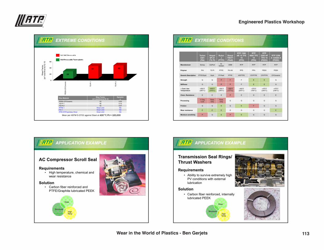
9/28/2016
16
EXTREME CONDITIONS
Not Melt Processable
Melt Processable Thermoplastic
0
20
40
60
PEEK
-CF/
Cer
amic
TS-P
I 1
TS-P
I 2
23
40 42
Wea
r Fac
tor
(in3 -
min
/ft-lb
-hr)
*E-1
0
Disc Material Wear Factor(in3-min/ft-lb-hr)*E-10
Dynamicµ
PEEK-CF/Ceramic 23 0.05TS-PI 1 40 0.10TS-PI 2 42 0.07PTFE 1 Wear Limit NAPAI 1 Wear Limit NAPPS-CF/Proprietary Wear Wear Limit NA
Wear per ASTM D-3702 against Steel at 400°F; PV = 100,000
EXTREME CONDITIONS
Torlon 4301(PAI)
Vespel SP-21(TS PI)
Rulon J
(PTFE)
Stanyl TW371(PA46)
RTP 1300 AR 15 TFE
15(PPS)
RTP 4085 TFE
15(PPA)
RTP 2285 HF TFE 15 (PEEK)
RTP 2299 X 125404 A
(PEEK)
Manufacturer Solvay DuPont St.Gobain DSM RTP RTP RTP RTP
Polymer PAI TS PI PTFE PA 4/6 PPS PPA PEEK PEEK
Generic Description PTFE/Grph Grph PI Pwdr PTFE AF/PTFE CF/PTFE CF/PTFE CF/Ceramic
Strength G G P F F E E G
Stiffness G G P P F E E G
~ Cont. UseTemperature
>500°F (260°C)
>600°F (316°C)
~550°F(290°C)
~350°F(177°C)
~400°F(205°C)
~375°F(190°C)
~475°F(246°C)
~475°F(246°C)
Chem. Resistance E E E P E G E E
Processing 17 Day Cure
Parts Only
Parts Only G G G G G
Friction G G E G E F G G
Wear resistance E E E G G G G E
Moisture sensitivity P G E P E G G G
APPLICATION EXAMPLE
AC Compressor Scroll Seal
Requirements• High temperature, chemical and
wear resistance
Solution• Carbon fiber reinforced and
PTFE/Graphite lubricated PEEK
Structural
Wear
HighTemp
APPLICATION EXAMPLE
Transmission Seal Rings/Thrust WashersRequirements
• Ability to survive extremely high PV conditions with external lubrication
Solution• Carbon fiber reinforced, internally
lubricated PEEK
Structural
Wear
HighTemp
113Wear in the World of Plastics - Ben Gerjets
Engineered Plastics Workshop
9/28/2016
17
WEAR AND FRICTION ADDITIONAL INFORMATION
Wear Factor (K) and friction coefficient (µK) for common tribological compounds:www.rtpcompany.com/info/wear
rtpcompany.com [email protected]
Thank You!
Ben [email protected](507) 474-5381
114Wear in the World of Plastics - Ben Gerjets
Engineered Plastics Workshop
Color - More than Meets the Eye
Jesse Dulek | Product Development [email protected](507) 474-5502
3:15 p.m.115
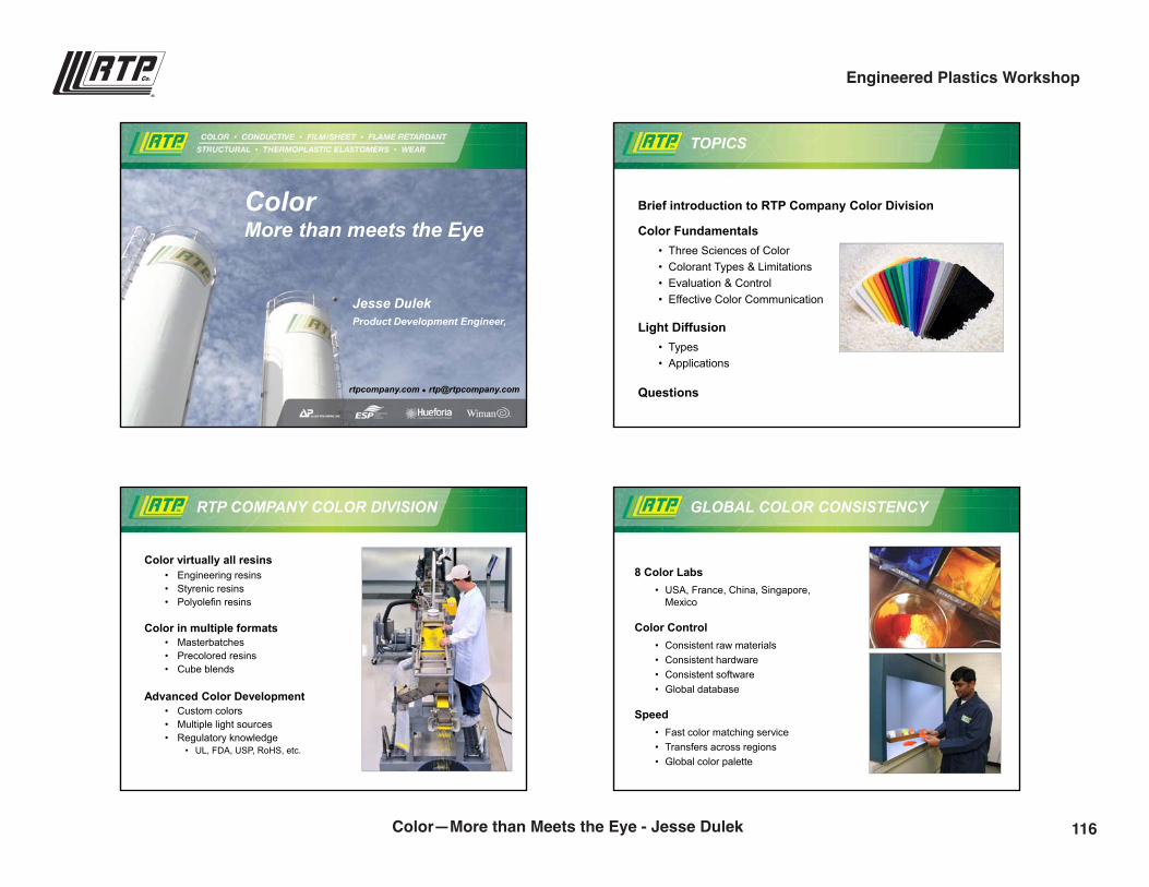
9/28/2016
1
rtpcompany.com [email protected]
ColorMore than meets the Eye
Jesse DulekProduct Development Engineer,
TOPICS
Brief introduction to RTP Company Color Division
Color Fundamentals• Three Sciences of Color• Colorant Types & Limitations• Evaluation & Control• Effective Color Communication
Light Diffusion• Types• Applications
Questions
RTP COMPANY COLOR DIVISION
Color virtually all resins• Engineering resins• Styrenic resins• Polyolefin resins
Color in multiple formats• Masterbatches• Precolored resins• Cube blends
Advanced Color Development• Custom colors • Multiple light sources• Regulatory knowledge
• UL, FDA, USP, RoHS, etc.
RTP Color 2008
GLOBAL COLOR CONSISTENCY
8 Color Labs• USA, France, China, Singapore,
Mexico
Color Control• Consistent raw materials• Consistent hardware• Consistent software• Global database
Speed• Fast color matching service• Transfers across regions• Global color palette
116Color—More than Meets the Eye - Jesse Dulek
Engineered Plastics Workshop
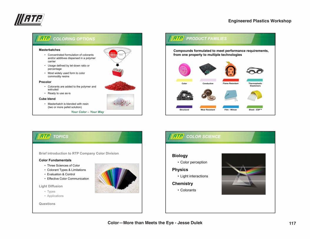
9/28/2016
2
COLORING OPTIONS
Masterbatches• Concentrated formulation of colorants
and/or additives dispersed in a polymer carrier
• Usage defined by let-down ratio or percentage
• Most widely used form to color commodity resins
Precolor• Colorants are added to the polymer and
extruded• Ready to use as-is
Cube blend• Masterbatch is blended with resin
(two or more pellet solution)
Your Color – Your Way
ResinMaster batch
PRODUCT FAMILIES
Compounds formulated to meet performance requirements, from one property to multiple technologies
Color Conductive Flame Retardant Thermoplastic Elastomers
Structural Wear Resistant Film - Wiman Sheet - ESP™
TOPICS
Brief introduction to RTP Company Color Division
Color Fundamentals• Three Sciences of Color• Colorant Types & Limitations• Evaluation & Control• Effective Color Communication
Light Diffusion• Types• Applications
Questions
Biology• Color perception
Physics• Light interactions
Chemistry• Colorants
COLOR SCIENCE
117Color—More than Meets the Eye - Jesse Dulek
Engineered Plastics Workshop
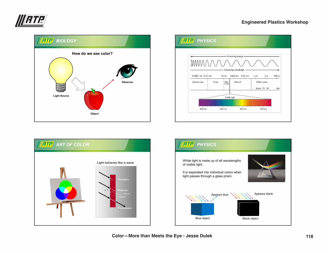
9/28/2016
3
BIOLOGY
How do we see color?
Light Source
Object
Observer
PHYSICS
ART OF COLOR
Light behaves like a wave
PHYSICS
White light is made up of all wavelengths of visible light.
It is separated into individual colors when light passes through a glass prism.
Appears blue
Blue object
Appears black
Black object
118Color—More than Meets the Eye - Jesse Dulek
Engineered Plastics Workshop
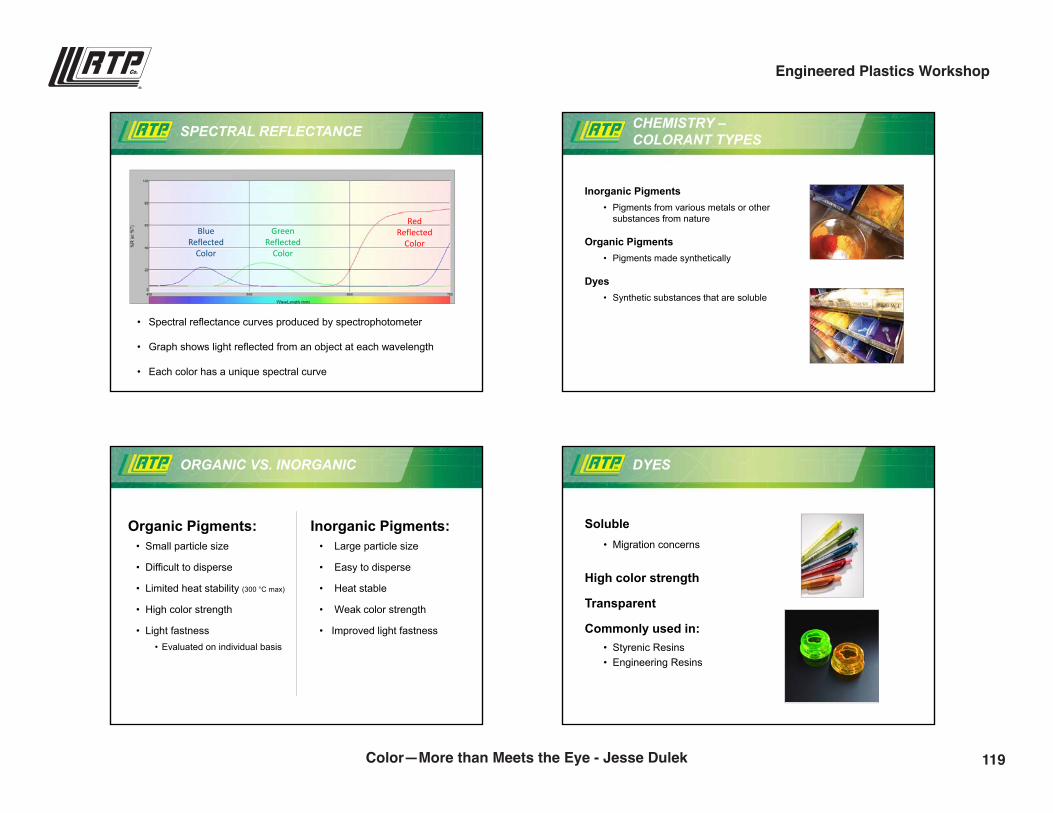
9/28/2016
4
SPECTRAL REFLECTANCE
• Spectral reflectance curves produced by spectrophotometer
• Graph shows light reflected from an object at each wavelength
• Each color has a unique spectral curve
Blue Reflected
Color
Green Reflected
Color
Red Reflected
Color
CHEMISTRY –COLORANT TYPES
Inorganic Pigments • Pigments from various metals or other
substances from nature
Organic Pigments • Pigments made synthetically
Dyes• Synthetic substances that are soluble
• Small particle size
• Difficult to disperse
• Limited heat stability (300 °C max)
• High color strength
• Light fastness• Evaluated on individual basis
ORGANIC VS. INORGANIC
Organic Pigments:• Large particle size
• Easy to disperse
• Heat stable
• Weak color strength
• Improved light fastness
Inorganic Pigments:
DYES
Soluble• Migration concerns
High color strength
Transparent
Commonly used in:• Styrenic Resins• Engineering Resins
119Color—More than Meets the Eye - Jesse Dulek
Engineered Plastics Workshop
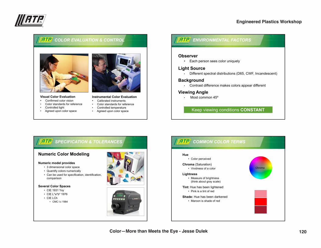
9/28/2016
5
COLOR EVALUATION & CONTROL
RTP Color 2008
Visual Color Evaluation• Confirmed color vision• Color standards for reference• Controlled light • Agreed upon color space
Instrumental Color Evaluation• Calibrated instruments• Color standards for reference• Controlled temperature• Agreed upon color space
ENVIRONMENTAL FACTORS
Observer• Each person sees color uniquely
Light Source• Different spectral distributions (D65, CWF, Incandescent)
Background• Contrast difference makes colors appear different
Viewing Angle• Most common 45º
Keep viewing conditions CONSTANT
SPECIFICATION & TOLERANCES
Numeric Color Modeling
Numeric model provides• 3 dimensional color space• Quantify colors numerically• Can be used for specification, identification,
comparison
Several Color Spaces• CIE 1931 Yxy• CIE L*a*b* 1976• CIE LCh
• CMC l:c 1984
COMMON COLOR TERMS
Hue• Color perceived
Chroma (Saturation)• Vividness of a color
Lightness• Measure of brightness
(think about gray scale)
Tint: Hue has been lightened• Pink is a tint of red
Shade: Hue has been darkened• Maroon is shade of red
Chroma
120Color—More than Meets the Eye - Jesse Dulek
Engineered Plastics Workshop
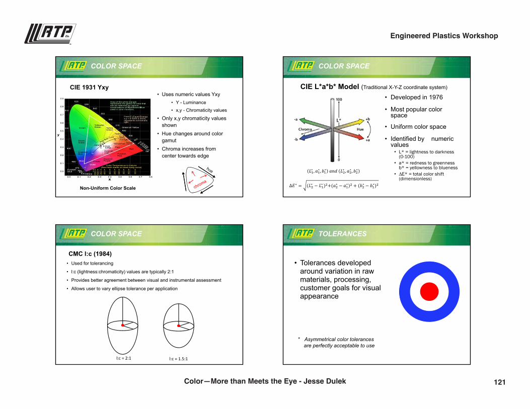
9/28/2016
6
• Uses numeric values Yxy• Y - Luminance• x,y - Chromaticity values
• Only x,y chromaticity values shown
• Hue changes around color gamut
• Chroma increases from center towards edge
COLOR SPACE
CIE 1931 Yxy
Non-Uniform Color Scale
• Developed in 1976
• Most popular color space
• Uniform color space
• Identified by numeric values
• L* = lightness to darkness (0-100)
• a* = redness to greenness b* = yellowness to blueness
• ∆E* = total color shift (dimensionless)
COLOR SPACE
RTP Color 2008
CIE L*a*b* Model (Traditional X-Y-Z coordinate system)
��∗ � ��∗� ��∗ ��� ��∗ � ��∗� ��∗
��∗ � ���∗ � ��∗ ������∗ � ��∗�� � ���∗ � ��∗��
COLOR SPACE
• Used for tolerancing
• l:c (lightness:chromaticity) values are typically 2:1
• Provides better agreement between visual and instrumental assessment
• Allows user to vary ellipse tolerance per application
CMC l:c (1984)
l:c = 2:1 l:c = 1.5:1
• Tolerances developed around variation in raw materials, processing, customer goals for visual appearance
TOLERANCES
* Asymmetrical color tolerancesare perfectly acceptable to use
121Color—More than Meets the Eye - Jesse Dulek
Engineered Plastics Workshop
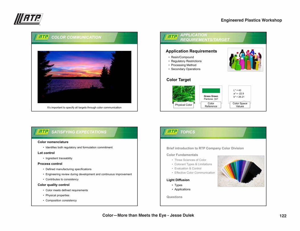
9/28/2016
7
COLOR COMMUNICATION
It’s important to specify all targets through color communication
L* = 43a* = -22.9b* = 26.21Grass Green
Pantone: 347
APPLICATION REQUIREMENTS/TARGET
Color Target
Application Requirements• Resin/Compound• Regulatory Restrictions• Processing Method• Secondary Operations
Physical Color Color Space Values
ColorReference
SATISFYING EXPECTATIONS
Color nomenclature• Identifies both regulatory and formulation commitment
Lot control• Ingredient traceability
Process control• Defined manufacturing specifications
• Engineering review during development and continuous improvement
• Contributes to consistency
Color quality control• Color meets defined requirements
• Physical properties
• Composition consistency
TOPICS
Brief introduction to RTP Company Color Division
Color Fundamentals• Three Sciences of Color• Colorant Types & Limitations• Evaluation & Control• Effective Color Communication
Light Diffusion• Types• Applications
Questions
122Color—More than Meets the Eye - Jesse Dulek
Engineered Plastics Workshop
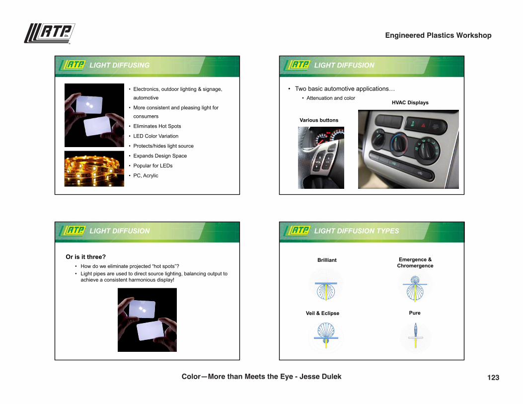
9/28/2016
8
LIGHT DIFFUSING
• Electronics, outdoor lighting & signage,
automotive
• More consistent and pleasing light for
consumers
• Eliminates Hot Spots
• LED Color Variation
• Protects/hides light source
• Expands Design Space
• Popular for LEDs
• PC, Acrylic
LIGHT DIFFUSION
• Two basic automotive applications…• Attenuation and color
HVAC Displays
Various buttons
LIGHT DIFFUSION
Or is it three?• How do we eliminate projected “hot spots”?• Light pipes are used to direct source lighting, balancing output to
achieve a consistent harmonious display!
LIGHT DIFFUSION TYPES
Brilliant Emergence & Chromergence
Veil & Eclipse Pure
123Color—More than Meets the Eye - Jesse Dulek
Engineered Plastics Workshop
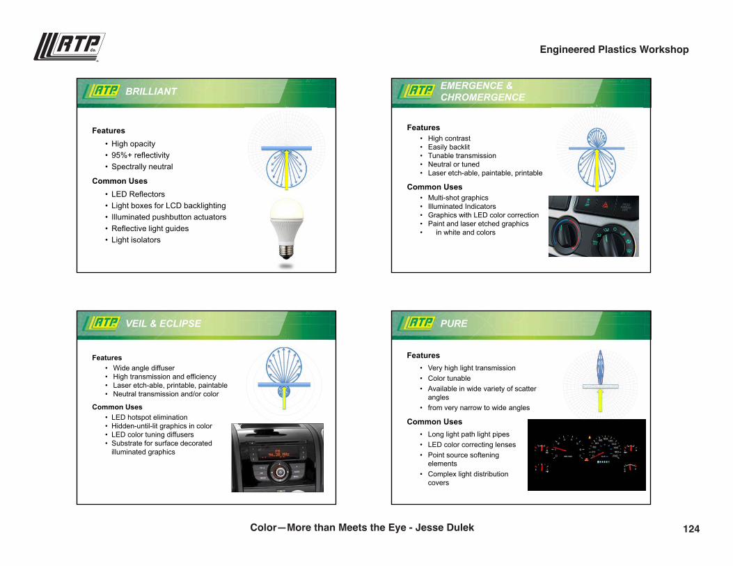
9/28/2016
9
BRILLIANT
Features• High opacity• 95%+ reflectivity• Spectrally neutral
Common Uses• LED Reflectors• Light boxes for LCD backlighting • Illuminated pushbutton actuators• Reflective light guides• Light isolators
EMERGENCE & CHROMERGENCE
Features• High contrast• Easily backlit• Tunable transmission• Neutral or tuned• Laser etch-able, paintable, printable
Common Uses• Multi-shot graphics• Illuminated Indicators• Graphics with LED color correction • Paint and laser etched graphics • in white and colors
VEIL & ECLIPSE
Features• Wide angle diffuser• High transmission and efficiency• Laser etch-able, printable, paintable• Neutral transmission and/or color
Common Uses• LED hotspot elimination• Hidden-until-lit graphics in color• LED color tuning diffusers• Substrate for surface decorated
illuminated graphics
PURE
Features• Very high light transmission• Color tunable• Available in wide variety of scatter
angles• from very narrow to wide angles
Common Uses• Long light path light pipes• LED color correcting lenses • Point source softening
elements• Complex light distribution
covers
124Color—More than Meets the Eye - Jesse Dulek
Engineered Plastics Workshop
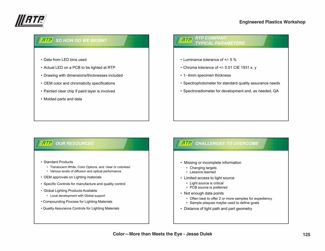
9/28/2016
10
SO HOW DO WE BEGIN?
• Data from LED bins used
• Actual LED on a PCB to be lighted at RTP
• Drawing with dimensions/thicknesses included
• OEM color and chromaticity specifications
• Painted clear chip if paint layer is involved
• Molded parts and data
RTP COMPANY TYPICAL PARAMETERS
• Luminance tolerance of +/- 5 %
• Chroma tolerance of +/- 0.01 CIE 1931 x, y
• 1- 4mm specimen thickness
• Spectrophotometer for standard quality assurance needs
• Spectroradiometer for development and, as needed, QA
OUR RESOURCES
• Standard Products • Translucent White, Color Options, and ‘clear or colorless’ • Various levels of diffusion and optical performance
• OEM approvals on Lighting materials
• Specific Controls for manufacture and quality control
• Global Lighting Products Available• Local development with Global support
• Compounding Process for Lighting Materials
• Quality Assurance Controls for Lighting Materials
CHALLENGES TO OVERCOME
• Missing or incomplete information• Changing targets• Lessons learned
• Limited access to light source• Light source is critical • PCB source is preferred
• Not enough data points• Often best to offer 2 or more samples for expediency• Sample plaques maybe used to define goals
• Distance of light path and part geometry
125Color—More than Meets the Eye - Jesse Dulek
Engineered Plastics Workshop

9/28/2016
11
COMMUNICATION IS KEY
• Luminance transmission
• Spectral transmission
• Most applications require reporting “Day and Night” performance
• X-Rite I7 Spectrophotometer• D65 SCI 10 degree, LAV• Black and white background defined thickness
• Minolta CS-2000• Preferred customer source• RTP source as alternative
How do we share information?
LIGHT DIFFUSION REVIEW
Brilliant Emergence & Chromergence
Veil & Eclipse Pure
SUMMARY
• RTP Company supplies innovative colors and functional additives
• Color communication is crucial to color matching and tolerancing
• Application is key to setting tolerance!
• Light diffusion applications and types
• Communication is key and we are here to help!
QUESTIONS
Any Questions
126Color—More than Meets the Eye - Jesse Dulek
Engineered Plastics Workshop
9/28/2016
12
rtpcompany.com [email protected]
Thank You!
Jesse [email protected](507) 474-5502
127Color—More than Meets the Eye - Jesse Dulek
Engineered Plastics Workshop
Everything You Need toKnow about TPEs
Karl Hoppe | Senior Product Development [email protected](507) 474-5367
4:00 p.m.
129
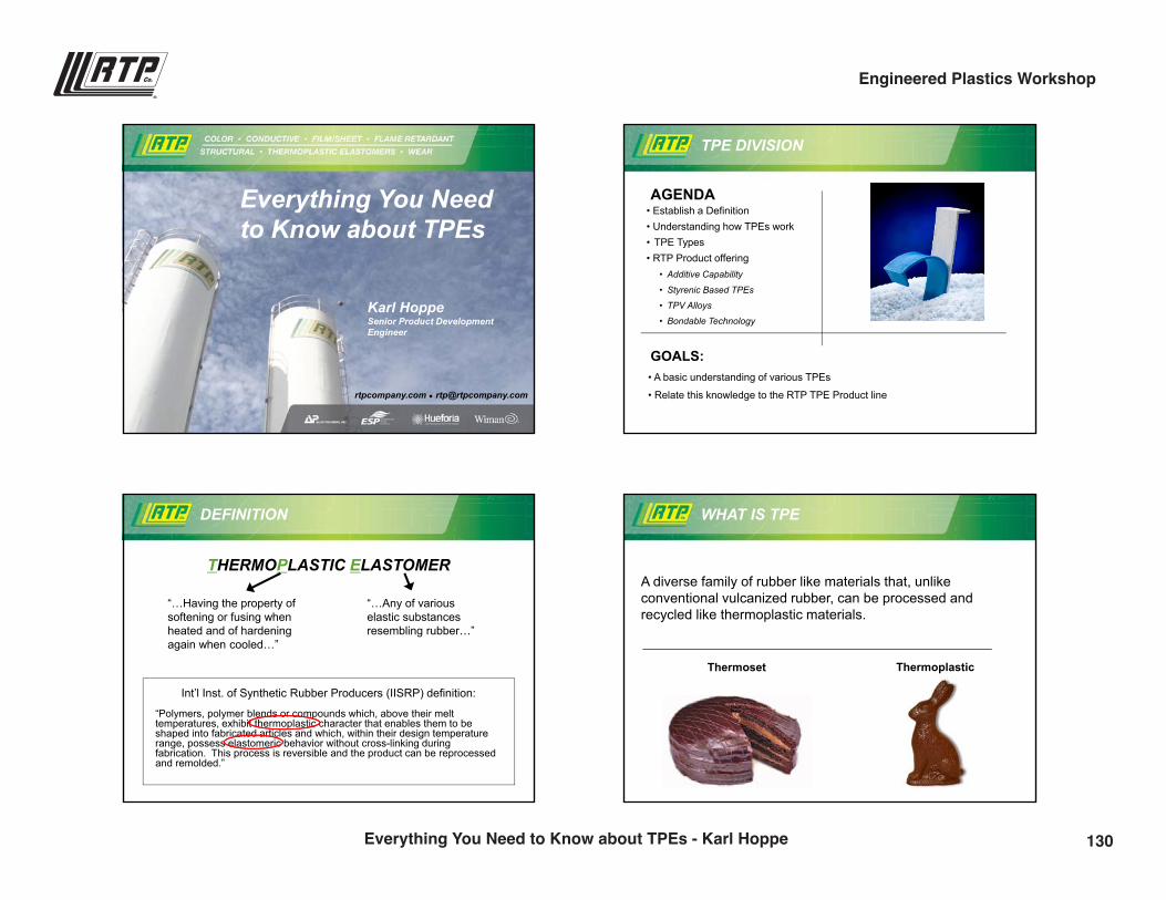
9/28/2016
1
rtpcompany.com [email protected]
Everything You Need to Know about TPEs
Karl HoppeSenior Product Development Engineer
TPE DIVISION
AGENDA
GOALS:• A basic understanding of various TPEs
• Relate this knowledge to the RTP TPE Product line
• Establish a Definition• Understanding how TPEs work• TPE Types• RTP Product offering
• Additive Capability
• Styrenic Based TPEs
• TPV Alloys
• Bondable Technology
DEFINITION
THERMOPLASTIC ELASTOMER
Int’l Inst. of Synthetic Rubber Producers (IISRP) definition:
“Polymers, polymer blends or compounds which, above their melt temperatures, exhibit thermoplastic character that enables them to be shaped into fabricated articles and which, within their design temperature range, possess elastomeric behavior without cross-linking during fabrication. This process is reversible and the product can be reprocessed and remolded.”
“…Having the property of softening or fusing when heated and of hardening again when cooled…”
“…Any of various elastic substances resembling rubber…”
WHAT IS TPE
A diverse family of rubber like materials that, unlike conventional vulcanized rubber, can be processed and recycled like thermoplastic materials.
Thermoset Thermoplastic
130Everything You Need to Know about TPEs - Karl Hoppe
Engineered Plastics Workshop
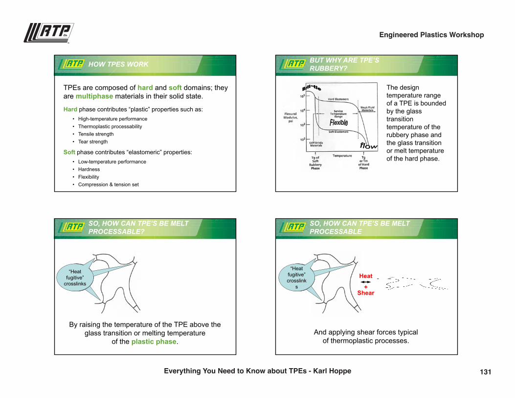
9/28/2016
2
HOW TPES WORK
TPEs are composed of hard and soft domains; they are multiphase materials in their solid state.
Hard phase contributes “plastic” properties such as: • High-temperature performance• Thermoplastic processability• Tensile strength• Tear strength
Soft phase contributes “elastomeric” properties: • Low-temperature performance • Hardness• Flexibility • Compression & tension set
BUT WHY ARE TPE’S RUBBERY?
The design temperature range of a TPE is bounded by the glass transitiontemperature of the rubbery phase and the glass transition or melt temperature of the hard phase.
SO, HOW CAN TPE’S BE MELT PROCESSABLE?
Heat
By raising the temperature of the TPE above the glass transition or melting temperature
of the plastic phase.
“Heatfugitive”
crosslinks
SO, HOW CAN TPE’S BE MELT PROCESSABLE
“Heatfugitive”crosslink
s
Heat
+ Shear
And applying shear forces typical of thermoplastic processes.
131Everything You Need to Know about TPEs - Karl Hoppe
Engineered Plastics Workshop
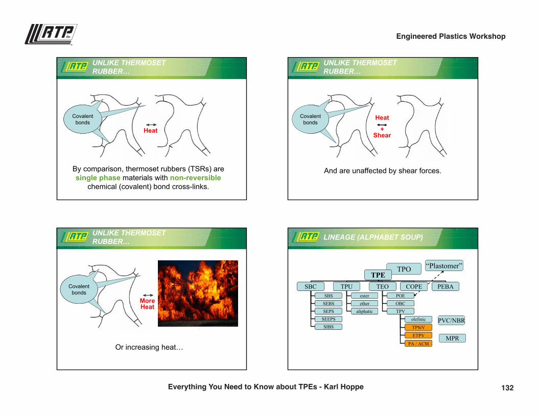
9/28/2016
3
UNLIKE THERMOSET RUBBER…
Covalentbonds
Heat
By comparison, thermoset rubbers (TSRs) are single phase materials with non-reversible
chemical (covalent) bond cross-links.
UNLIKE THERMOSET RUBBER…
And are unaffected by shear forces.
Heat
+ Shear
Covalentbonds
UNLIKE THERMOSET RUBBER…
Covalentbonds
More Heat
Or increasing heat…
LINEAGE (ALPHABET SOUP)
TPO “Plastomer”TPE
SBC TPU COPE PEBAesterether
aliphatic
SBSSEBSSEPS
SIBSSEEPS
TEOPOE
TPV
olefinic
ETPV
TPSiV
PA / ACM
OBC
TPESBC TPU COPE PEBA
esterether
aliphatic
SBSSEBSSEPS
SIBSSEEPS
TEOPOE
TPV
olefinic
ETPV
TPSiV
PA / ACM
OBC
PVC/NBR
MPR
132Everything You Need to Know about TPEs - Karl Hoppe
Engineered Plastics Workshop
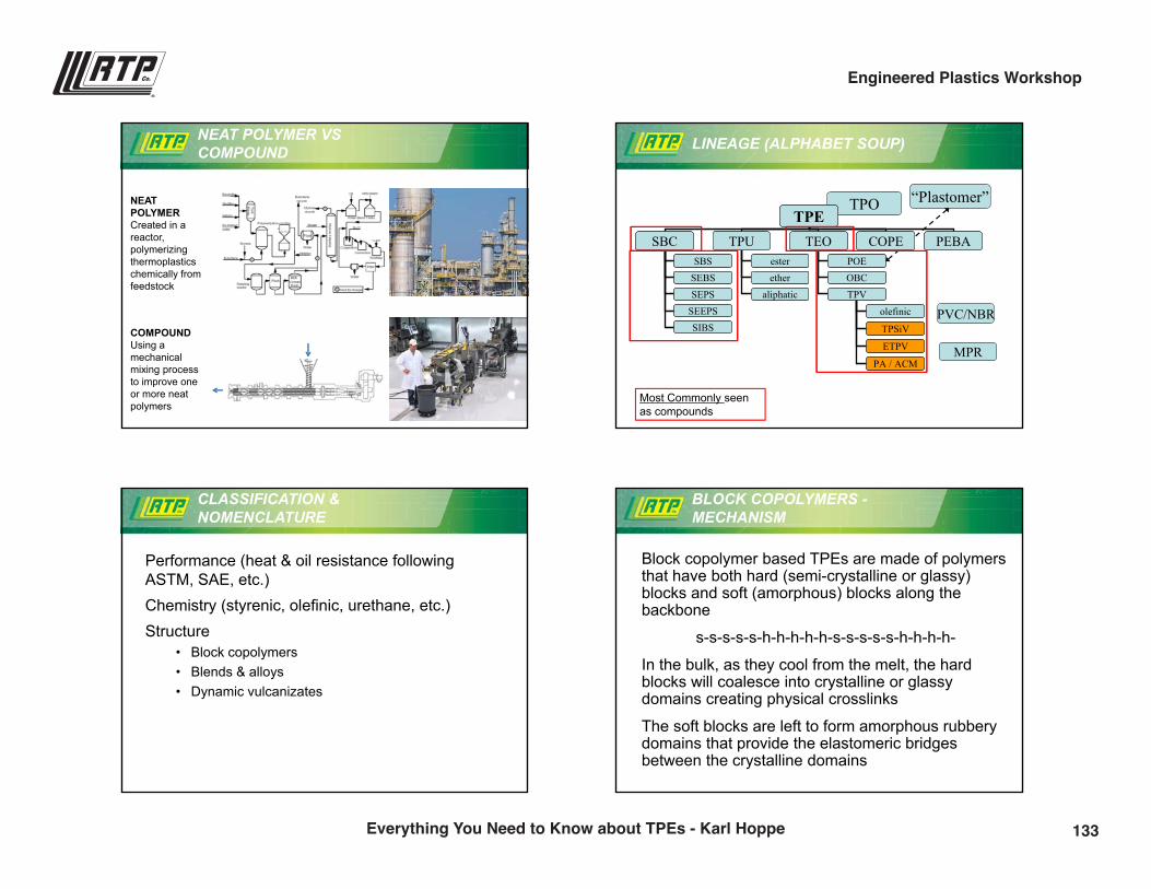
9/28/2016
4
NEAT POLYMER VSCOMPOUND
NEAT POLYMER Created in a reactor, polymerizing thermoplasticschemically from feedstock
COMPOUNDUsing a mechanicalmixing process to improve one or more neat polymers
LINEAGE (ALPHABET SOUP)
TPO “Plastomer”TPE
SBC TPU COPE PEBAesterether
aliphatic
SBSSEBSSEPS
SIBSSEEPS
TEOPOE
TPV
olefinic
ETPV
TPSiV
PA / ACM
OBC
TPESBC TPU COPE PEBA
esterether
aliphatic
SBSSEBSSEPS
SIBSSEEPS
TEOPOE
TPV
olefinic
ETPV
TPSiV
PA / ACM
OBC
PVC/NBR
MPR
Most Commonly seen as compounds
CLASSIFICATION & NOMENCLATURE
Performance (heat & oil resistance following ASTM, SAE, etc.)Chemistry (styrenic, olefinic, urethane, etc.)Structure
• Block copolymers• Blends & alloys• Dynamic vulcanizates
BLOCK COPOLYMERS -MECHANISM
Block copolymer based TPEs are made of polymers that have both hard (semi-crystalline or glassy) blocks and soft (amorphous) blocks along the backbone
s-s-s-s-s-h-h-h-h-h-s-s-s-s-s-h-h-h-h-
In the bulk, as they cool from the melt, the hard blocks will coalesce into crystalline or glassy domains creating physical crosslinks
The soft blocks are left to form amorphous rubbery domains that provide the elastomeric bridges between the crystalline domains
133Everything You Need to Know about TPEs - Karl Hoppe
Engineered Plastics Workshop
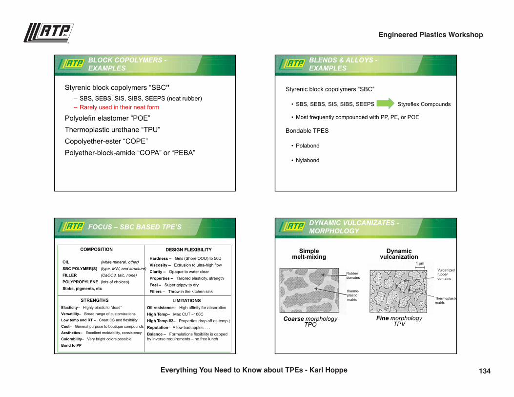
9/28/2016
5
BLOCK COPOLYMERS -EXAMPLES
Styrenic block copolymers “SBC”– SBS, SEBS, SIS, SIBS, SEEPS (neat rubber)– Rarely used in their neat form
Polyolefin elastomer “POE”Thermoplastic urethane “TPU”Copolyether-ester “COPE”Polyether-block-amide “COPA” or “PEBA”
BLENDS & ALLOYS -EXAMPLES
Styrenic block copolymers “SBC”
• SBS, SEBS, SIS, SIBS, SEEPS Styreflex Compounds
• Most frequently compounded with PP, PE, or POE
Bondable TPES
• Polabond
• Nylabond
FOCUS – SBC BASED TPE’S
COMPOSITION DESIGN FLEXIBILITY
STRENGTHS LIMITATIONS
OIL SBC POLYMER(S) FILLER POLYPROPYLENE Stabs, pigments, etc
(white mineral, other)(type, MW, and structure)(CaCO3, talc, none)(lots of choices)
Hardness – Gels (Shore OOO) to 50D Viscosity – Extrusion to ultra-high flowClarity – Opaque to water clearProperties – Tailored elasticity, strength Feel – Super grippy to dryFillers – Throw in the kitchen sink
Elasticity– Highly elastic to “dead”
Versatility– Broad range of customizations
Low temp and RT – Great CS and flexibility
Cost– General purpose to boutique compounds
Aesthetics– Excellent moldability, consistency
Colorability– Very bright colors possible
Bond to PP
Oil resistance– High affinity for absorptionHigh Temp– Max CUT ~100CHigh Temp #2– Properties drop off as temp ↑Reputation– A few bad apples . . . Balance – Formulations flexibility is capped by inverse requirements – no free lunch
DYNAMIC VULCANIZATES -MORPHOLOGY
Fine morphologyTPV
Dynamic vulcanization
Simplemelt-mixing
Coarse morphologyTPO
Rubberdomains
thermo-plastic matrix
Vulcanizedrubber domains
Thermoplasticmatrix
134Everything You Need to Know about TPEs - Karl Hoppe
Engineered Plastics Workshop
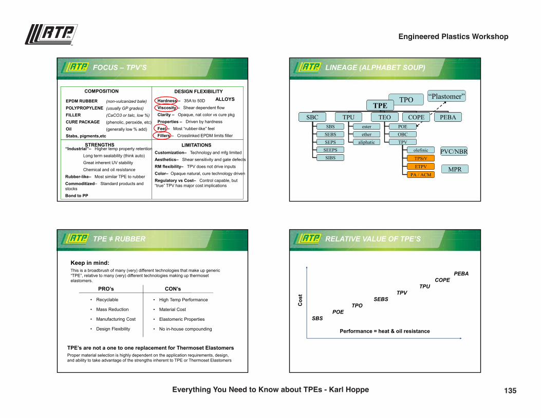
9/28/2016
6
FOCUS – TPV’S
COMPOSITION DESIGN FLEXIBILITY
STRENGTHS LIMITATIONS
EPDM RUBBER POLYPROPYLENEFILLER CURE PACKAGE Oil Stabs, pigments,etc
(non-vulcanized bale)(usually GP grades)(CaCO3 or talc, low %)(phenolic, peroxide, etc)(generally low % add)
Hardness – 35A to 50D Viscosity – Shear dependent flowClarity – Opaque, nat color vs cure pkgProperties – Driven by hardnessFeel – Most “rubber-like” feelFillers – Crosslinked EPDM limits filler
“Industrial”– Higher temp property retentionLong term sealability (think auto)Great inherent UV stabilityChemical and oil resistance
Rubber-like– Most similar TPE to rubberCommoditized– Standard products and stocksBond to PP
Customization– Technology and mfg limitedAesthetics– Shear sensitivity and gate defectsRM flexibility– TPV does not drive inputsColor– Opaque natural, cure technology drivenRegulatory vs Cost– Control capable, but “true” TPV has major cost implications
ALLOYS
LINEAGE (ALPHABET SOUP)
TPO “Plastomer”TPE
SBC TPU COPE PEBAesterether
aliphatic
SBSSEBSSEPS
SIBSSEEPS
TEOPOE
TPV
olefinic
ETPV
TPSiV
PA / ACM
OBC
TPESBC TPU COPE PEBA
esterether
aliphatic
SBSSEBSSEPS
SIBSSEEPS
TEOPOE
TPV
olefinic
ETPV
TPSiV
PA / ACM
OBC
PVC/NBR
MPR
TPE ≠ RUBBER
Keep in mind:This is a broadbrush of many (very) different technologies that make up generic “TPE”, relative to many (very) different technologies making up thermoset elastomers.
• Recyclable
• Mass Reduction
• Manufacturing Cost
• Design Flexibility
PRO’s CON’s
• High Temp Performance
• Material Cost
• Elastomeric Properties
• No in-house compounding
TPE’s are not a one to one replacement for Thermoset ElastomersProper material selection is highly dependent on the application requirements, design, and ability to take advantage of the strengths inherent to TPE or Thermoset Elastomers
RELATIVE VALUE OF TPE’S
PEBACOPE
TPUTPV
SEBSTPO
POESBS
Performance = heat & oil resistance
Cos
t
135Everything You Need to Know about TPEs - Karl Hoppe
Engineered Plastics Workshop
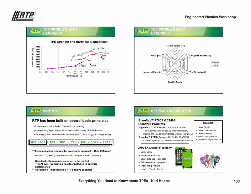
9/28/2016
7
THE PROBLEM WITH HARDNESS
0100020003000400050006000700080009000
Tens
ile S
tren
gth
(psi
)
Hardness (Shore)
TPE Strength and Hardness Comparison
30A 40A 50A 60A 70A20A 80A30D
90A40D
TPUCOPE
TPV
SBC
50D 60D 70D 80D 90D
PEBA
PP
LDPE
THE PROBLEM WITH HARDNESS
WHY RTP?
RTP has been built on several basic principles:
TPE compounding requires the exact same approach – Only Different?
SBS • POE • TES • SBC • TPV • TPU • COPE • PEBA
• Independent, Value Added Custom Compounding
• Incorporating Specialty Additives into a Wide Variety of Base Resins
• Very Highly Focused on (and invested in) R&D, Technology, and Engineering
• Standard – Compounds common to the market• TPE Alloys – Combining neat technologies to optimize
performance• Specialties – Incorporating RTP additive expertise
• Mix R&D / Engineering capability with ability to supply “volume” compounds
STYRENIC BASED TPE’S
Styreflex™ 2700S & 2740S Standard ProductsStyreflex™ 2700 S Series - 30A to 80A unfilled
• Translucent to clear, low gravity, excellent elasticity• Medical and FDA compliant grades available (MD and Z)
Styreflex™ 2740S Series - 30A to 80A filled SBC• Opaque, higher gravity, FDA compliant grades available
Attributes
• Highly Elastic• Highly Customizable• Design Flexibility• Broad Cost Spectrum• Great RT Compression Set
2799 SX Design Flexibility• Water clear• Increased Elasticity• Low Hardness + Strength• EU food contact compliant• Processing Tweaks• Haptics (Touchy-Feely)
136Everything You Need to Know about TPEs - Karl Hoppe
Engineered Plastics Workshop
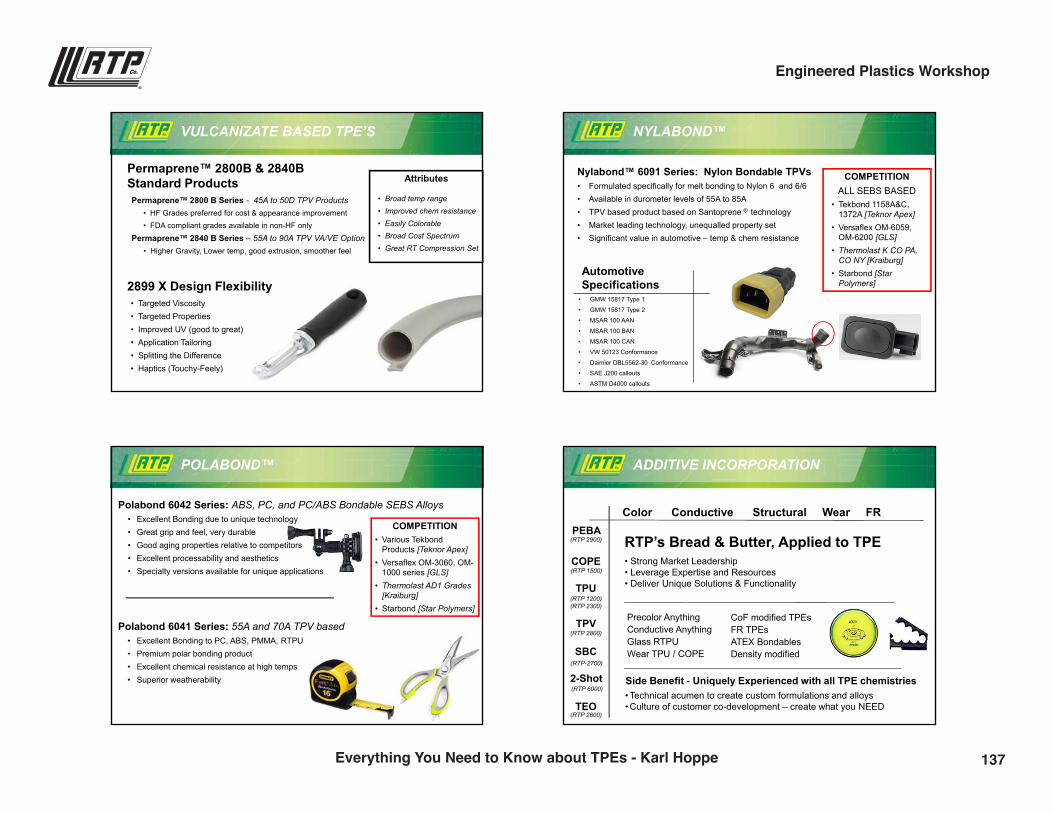
9/28/2016
8
VULCANIZATE BASED TPE’S
Permaprene™ 2800B & 2840B Standard ProductsPermaprene™ 2800 B Series - 45A to 50D TPV Products
• HF Grades preferred for cost & appearance improvement • FDA compliant grades available in non-HF only
Permaprene™ 2840 B Series – 55A to 90A TPV VA/VE Option• Higher Gravity, Lower temp, good extrusion, smoother feel
2899 X Design Flexibility• Targeted Viscosity• Targeted Properties• Improved UV (good to great)• Application Tailoring• Splitting the Difference• Haptics (Touchy-Feely)
Attributes
• Broad temp range• Improved chem resistance• Easily Colorable• Broad Cost Spectrum• Great RT Compression Set
NYLABOND™
Nylabond™ 6091 Series: Nylon Bondable TPVs• Formulated specifically for melt bonding to Nylon 6 and 6/6• Available in durometer levels of 55A to 85A• TPV based product based on Santoprene ® technology• Market leading technology, unequalled property set • Significant value in automotive – temp & chem resistance
Automotive Specifications
• GMW 15817 Type 1
• GMW 15817 Type 2
• MSAR 100 AAN
• MSAR 100 BAN
• MSAR 100 CAN
• VW 50123 Conformance
• Daimler DBL5562-30 Conformance
• SAE J200 callouts
• ASTM D4000 callouts
COMPETITIONALL SEBS BASED
• Tekbond 1158A&C, 1372A [Teknor Apex]
• Versaflex OM-6059, OM-6200 [GLS]
• Thermolast K CO PA, CO NY [Kraiburg]
• Starbond [StarPolymers]
POLABOND™
Polabond 6042 Series: ABS, PC, and PC/ABS Bondable SEBS Alloys• Excellent Bonding due to unique technology• Great grip and feel, very durable• Good aging properties relative to competitors• Excellent processability and aesthetics• Specialty versions available for unique applications
COMPETITION• Various Tekbond
Products [Teknor Apex]• Versaflex OM-3060, OM-
1000 series [GLS]• Thermolast AD1 Grades
[Kraiburg]• Starbond [Star Polymers]
Polabond 6041 Series: 55A and 70A TPV based • Excellent Bonding to PC, ABS, PMMA, RTPU• Premium polar bonding product• Excellent chemical resistance at high temps• Superior weatherability
ADDITIVE INCORPORATION
PEBA
COPE
TPU
TPV
SBC
TEO
RTP’s Bread & Butter, Applied to TPE• Strong Market Leadership• Leverage Expertise and Resources• Deliver Unique Solutions & Functionality
Precolor AnythingConductive AnythingGlass RTPUWear TPU / COPE
(RTP 1200)(RTP 2300)
(RTP 6000)
CoF modified TPEs FR TPEs ATEX BondablesDensity modified
Side Benefit - Uniquely Experienced with all TPE chemistries• Technical acumen to create custom formulations and alloys• Culture of customer co-development – create what you NEED
Color Conductive Structural Wear FR
(RTP-2700)
(RTP 2800)
(RTP 2900)
(RTP 1500)
2-Shot
(RTP 2600)
137Everything You Need to Know about TPEs - Karl Hoppe
Engineered Plastics Workshop
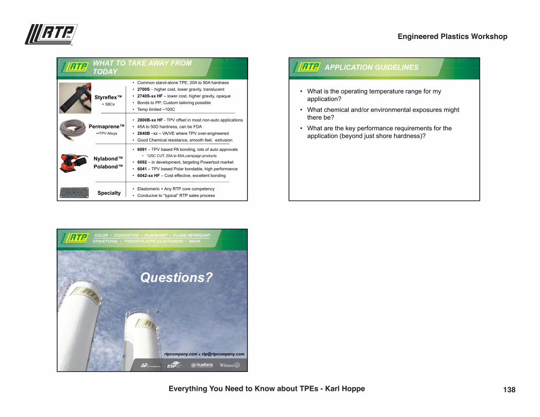
9/28/2016
9
WHAT TO TAKE AWAY FROM TODAY
Specialty
Styreflex™ - SBCs
• Common stand-alone TPE; 20A to 90A hardness• 2700S – higher cost, lower gravity, translucent• 2740S-xx HF – lower cost, higher gravity, opaque• Bonds to PP; Custom tailoring possible• Temp limited ~100C
Permaprene™ –TPV Alloys
Nylabond™Polabond™
• 2800B-xx HF - TPV offset in most non-auto applications• 45A to 50D hardness, can be FDA• 2840B –xx – VA/VE where TPV over-engineered• Good Chemical resistance, smooth feel, extrusion
• 6091 – TPV based PA bonding, lots of auto approvals• 125C CUT, 55A to 85A,campaign products
• 6092 – in development, targeting Powertool market• 6041 – TPV based Polar bondable, high performance• 6042-xx HF – Cost effective, excellent bonding
• Elastomeric + Any RTP core competency• Conducive to “typical” RTP sales process
APPLICATION GUIDELINES
• What is the operating temperature range for my application?
• What chemical and/or environmental exposures might there be?
• What are the key performance requirements for the application (beyond just shore hardness)?
rtpcompany.com [email protected]
Questions?
138Everything You Need to Know about TPEs - Karl Hoppe
Engineered Plastics Workshop
![[MS-RTP]: Real-time Transport Protocol (RTP) ExtensionsMS-RTP... · The Real-Time Transport Protocol (RTP) Extensions specifies a set of proprietary extensions to the base Real-Time](https://static.fdocuments.in/doc/165x107/5fcb11338738b8501a5201b4/ms-rtp-real-time-transport-protocol-rtp-extensions-ms-rtp-the-real-time.jpg)