Engine Timing Tools Part No. 4419 VAG 1.6 | 2.0 TDi CR · Part No. 5130 Incorrect or out of phase...
6
www.lasertools.co.uk Part No. 5130 www.lasertools.co.uk Incorrect or out of phase engine timing can result in damage to the valves. Tool Connection cannot be held responsible for any damage caused by using these tools in anyway. Safety Precautions – Please read • Disconnect the battery earth leads (check radio code is available) • Remove spark or glow plugs to make the engine turn easier • Do not use cleaning fluids on belts, sprockets or rollers • Always make a note of the route of the auxiliary drive belt before removal • Turn the engine in the normal direction (clockwise unless stated otherwise) • Do not turn the camshaft, crankshaft or diesel injection pump once the timing chain has been removed (unless specifically stated) • Do not use the timing chain to lock the engine when slackening or tightening crankshaft pulley bolts • Do not turn the crankshaft or camshaft when the timing belt/chain has been removed • Mark the direction of the chain before removing • It is always recommended to turn the engine slowly, by hand and to re-check the camshaft and crankshaft timing positions. • Crankshafts and Camshafts may only be turned with the chain drive mechanism fully installed. • Do not turn crankshaft via camshaft or other gears • Check the diesel injection pump timing after replacing the chain • Observe all tightening torques • Always refer to the vehicle manufacturer’s service manual or a suitable proprietary instruction book • Incorrect or out of phase engine timing can result in damage to the valves • It is always recommended to turn the engine slowly, by hand, and to re-check the camshaft and crankshaft timing positions Part No. 4419 Engine Timing Tools VAG 1.6 | 2.0 TDi CR
-
Upload
nguyenquynh -
Category
Documents
-
view
223 -
download
1
Transcript of Engine Timing Tools Part No. 4419 VAG 1.6 | 2.0 TDi CR · Part No. 5130 Incorrect or out of phase...
www.lasertools.co.uk
Part No. 5130
www.lasertools.co.uk
Incorrect or out of phase engine timing can result in damage to the valves. Tool Connection cannot be held responsible for any damage caused by using these tools in anyway.
Safety Precautions – Please read
• Disconnect the battery earth leads (check radio code is available)
• Remove spark or glow plugs to make the engine turn easier
• Do not use cleaning fluids on belts, sprockets or rollers
• Always make a note of the route of the auxiliary drive belt before removal
• Turn the engine in the normal direction (clockwise unless stated otherwise)
• Do not turn the camshaft, crankshaft or diesel injection pump once the timing chain has been removed (unless specifically stated)
• Do not use the timing chain to lock the engine when slackening or tightening crankshaft pulley bolts
• Do not turn the crankshaft or camshaft when the timing belt/chain has been removed
• Mark the direction of the chain before removing
• It is always recommended to turn the engine slowly, by hand and to re-check the camshaft and crankshaft timing positions.
• Crankshafts and Camshafts may only be turned with the chain drive mechanism fully installed.
• Do not turn crankshaft via camshaft or other gears
• Check the diesel injection pump timing after replacing the chain
• Observe all tightening torques
• Always refer to the vehicle manufacturer’s service manual or a suitable proprietary instruction book
• Incorrect or out of phase engine timing can result in damage to the valves
• It is always recommended to turn the engine slowly, by hand, and to re-check the camshaft and crankshaft timing positions
Part No. 4419 Engine Timing ToolsVAG 1.6 | 2.0 TDi CR

2 11
www.lasertools.co.ukwww.lasertools.co.uk
Plan Layout Instruction (DE)
Ref Code OEM Ref Description
A C216 T20102 | 3359 Injection Pump/Camshaft Alignment Pin
B C157 T10050 Crankshaft Pulley Locking Tool
C C304 T10100 Crankshaft Pulley Locking Tool
D C450 T10264 Ball End Hex Key 6mm
E C452 T40098 3.9mm Tensioner Pulley Locking Pin
F C451 T10265 2.5mm Tensioner Pulley Locking Pin
G C503 T10051 Sprocket Holding Tool
H C504 T10052 Cam Sprocket Hub Puller
I C505 T10255 Oil pump | Balancer Shaft Alignment
This kit has been designed to fit the newest Common Rail diesel engines which are significantly different from the older PD engines
These CR engines combine belt and gear drives by using a toothed belt to transfer the drive from the crankshaft to one of the cam shafts then using gears to transfer the drive from one cam to the other.
Beschreibung der Komponenten
Komponenten A Der Einspritzpumpen/Nockenwellen-Ausrichtstift wird eingesetzt, um die Nockenwelle in der richtigen Stellung zu fixieren. Dadurch kann das Nockenwellenrad gelöst werden, ohne dabei die Stellung der Nockenwelle zu ändern (immer ein geeignetes Fixierwerkzeug für das Zahnriemenrad verwenden, um Schäden am Stift zu vermeiden).
Komponenten B/CBei den Komponenten B und C handelt es sich um Arretierwerkzeuge für die Kurbelwellenstellung.
Sie funktionieren zwar nach dem gleichen Prinzip, sind aber unterschiedlich. Das für das Fahrzeug geeignete Werkzeug verwenden, so wie im Handbuch des Herstellers angegeben.
Hinweis: Bei einer Kurbelwellenscheibe, bei der das Werkzeug T10050 erforderlich ist, fluchtet die Einstellmarkierung mit einem Zahn. Bei einer Scheibe, bei der das Werkzeug T10100 erforderlich ist, befindet sich die Einstellmarkierung zwischen den Zähnen.
Vorarbeiten:Hinweis: Wenn diese Motoren in einer umgekehrten Konfiguration eingebaut sind, müssen Kühlergrill und Kühler ausgebaut werden. Um diesen Vorgang erheblich zu erleichtern, empfehlen wir den Einsatz des VAG Führungsstiftsatzes (Teilenr. 4637).
• Beim Austausch des Nocken-wellenriemens muss nur Folgendes ausgebaut werden:
Verdrahtung und Halterung des DPF-Drucksensors
Niederdruck-Kraftstoffsaugpumpe Radhaus innen Untere Motorabdeckung Zusatzantriebsriemen und -scheiben Riemenabdeckungen
45˚
B
A
C
Synchronisationswerkzeugsatz – VAG 1.6 | 2.0 TDi CR (DE)
Dieser Werkzeugsatz wurde für die neuesten Common-Rail-Dieselmotoren entwickelt, die sich erheblich von älteren Pumpe-Düse-Motoren unterscheiden.
Bei diesen CR-Motoren werden Riemen und Zahnradantriebe kombiniert, indem mit einem Zahnriemen die Kraft von der Kurbelwelle auf eine der Nockenwellen übertragen wird. Danach werden Zahnräder verwendet, um die Kraft von einer Nockenwelle auf die andere zu übertragen.
10 3
www.lasertools.co.uk www.lasertools.co.uk
Instruction (DE) Applications
The application list for this product has been compiled cross referencing the OEM Tool Code with the Component Code.
In most cases the tools are specific to this type of engine and are necessary for Cam belt or chain maintenance.
If the engine has been identified as an interference engine valve to piston damage will occur if the engine is run with a broken Cam belt.
A compression check of all cylinders should be performed before removing the cylinder head.
Always consult a suitable work shop manual before attempting to change the Cam belt or Chain.
The use of these engine timing tools is purely down to the user’s discretion and Tool Connection cannot be held responsible for any damage caused what so ever.
ALWAYS USE A REPUTABLE WORKSHOP MANUAL
Manufacturer Model Size Year Engine Code
Audi A3 1.6 2009- CAYB | CAYC
A3 | A4 | A6 | Q5 2.0 2007-CBAB | CBBB | CBAA | CFFB | CAGA CAHA | CAGB | CAHB | CAGC
Seat Exeo 2.0 2009- CAGA | CAHA | CAGA
VolkswagenGolf Golf Plus
1.6 2009- CAYB | CAYC
Tiguan Passat Eos Golf Golf Plus
2.0 2008FCA | CAAA | CAAB | CAAC | CCHA CAVA | CBAB | CBDA | CBDD | CBBB CBAA | CBAC | CBDA | CBDC
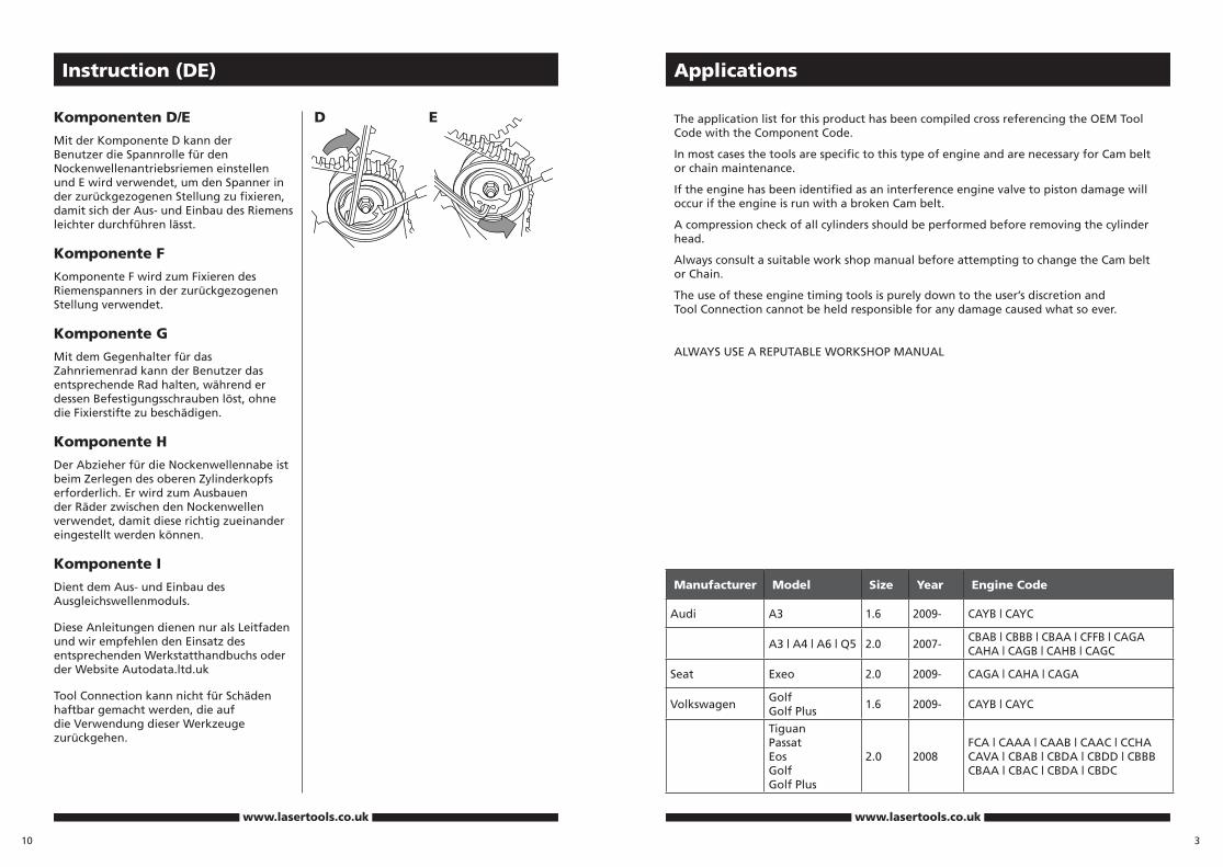
Komponenten D/E
Mit der Komponente D kann der Benutzer die Spannrolle für den Nockenwellenantriebsriemen einstellen und E wird verwendet, um den Spanner in der zurückgezogenen Stellung zu fixieren, damit sich der Aus- und Einbau des Riemens leichter durchführen lässt.
Komponente F
Komponente F wird zum Fixieren des Riemenspanners in der zurückgezogenen Stellung verwendet.
Komponente G
Mit dem Gegenhalter für das Zahnriemenrad kann der Benutzer das entsprechende Rad halten, während er dessen Befestigungsschrauben löst, ohne die Fixierstifte zu beschädigen.
Komponente H
Der Abzieher für die Nockenwellennabe ist beim Zerlegen des oberen Zylinderkopfs erforderlich. Er wird zum Ausbauen der Räder zwischen den Nockenwellen verwendet, damit diese richtig zueinander eingestellt werden können.
Komponente I
Dient dem Aus- und Einbau des Ausgleichswellenmoduls.
Diese Anleitungen dienen nur als Leitfaden und wir empfehlen den Einsatz des entsprechenden Werkstatthandbuchs oder der Website Autodata.ltd.uk
Tool Connection kann nicht für Schäden haftbar gemacht werden, die auf die Verwendung dieser Werkzeuge zurückgehen.
D E

4 9
www.lasertools.co.uk www.lasertools.co.uk
Instruction (ES)Instruction (GB)
Component Descriptions
Components A
The injection pump Camshaft alignment pin is used to hold the Camshaft in the correct position and allows the Cam sprocket to be loosened whilst maintaining the position of the camshaft (always use an appropriate sprocket holding tool to prevent damage to the pin).
Components B/C
Components B and C are both crankshaft position locking tools and
whilst they work on the same principle they are different. Use the appropriate tool unit for the vehicle as recommended by the manufacturers’ instructions.
NB: A crankshaft pulley requiring the T10050 has its timing mark aligned with a tooth where as a pulley requiring the T10100, the timing mark is between the teeth.
Componentes D/E
El componente D permite al usuario ajustar la polea tensionadora de la correa accionadora del eje de levas y E se utiliza para bloquear el tensor en la posición retraída para facilitar la retirada y montaje de la correa.
Componentes F
El componente F se utiliza para bloquear el tensor de correa auxiliar en su posición retraída.
Componentes G
La herramienta de sujeción de la rueda dentada G permite al usuario sujetar la rueda dentada adecuada mientras que se aflojan sus sujeciones sin dañar los pasadores de bloqueo.
Componente H
El extractor de buje del eje de levas se requiere para desmontar el cabezal del cilindro superior. Se utiliza para retirar los accionadores de leva a leva de forma que puedan sincronizarse con cada una correctamente.
Componente I
Para linear el módulo de eje de equilibrado.
Estas instrucciones son simplemente una guía y recomendamos el uso de un manual de taller adecuado o visite Autodata.ltd.uk.
The Tool Connection no puede considerarse responsable de ningún daño causado por la utilización de estas herramientas.
Preparation:
Note: Where these engines are mounted in front to back configuration it will be necessary to remove the front grill and radiators. To significantly ease this operation we recommend the use of the VAG Guide Pin Kit (Part No 4637)
• For camshaft drive belt replacement it is only necessary to remove:
• DPF pressure sensor wiring and bracket
• Low pressure fuel lift pump
• Inner wheel arch
• Engine under shield
• Auxiliary drive belts and pulleys
• Belt covers
45˚
B
A
C
D E

8
www.lasertools.co.uk
Engine Service Tool SetFiat | 1.3 JTD Engines
Instruction (ES)
Descripciones del componente
Componentes A
Se utiliza el pasador de alineación del eje de levas de la bomba de inyección para sujetar el eje de levas en la posición correcta y permitir que la rueda dentada de levas se afloje a la vez que se mantiene la posición del eje de levas (utilice siempre la herramienta de sujeción de la rueda dentada adecuada para evitar daños en el pasador).
Componentes B/C
Los componentes B y C son herramientas de bloqueo de posición del eje del cigüeñal y
aunque funcionan con el mismo principio son distintas: Utilice la herramienta adecuada para el vehículo tal y como recomiendan las instrucciones del fabricante.
Nota: Una polea de eje del cigüeñal que requiera que T10050 tenga su marca de sincronización alineada con un diente mientras que una polea que requiera el T10100, la marca de sincronización se encuentra entre los dientes.
45˚
B
A
C
Preparación:
Nota: Cuando se monten estos motores en la configuración de delante a atrás, será necesario retirar la rejilla delantera y el radiador. Para facilitar significativamente esta operación, recomendamos el uso del juego de pasadores de guía VAG (Nº de pieza 4637).
Juego de sincronización del motor - VAG 1.6 | 2.0 TD CR
Este juego ha sido diseñado para adaptarse a los nuevos motores diesel Common Rail que son significativamente distintos a los antiguos motores PD.
Estos motores CR combinan el accionamiento por cadena y correa mediante el uso de una correa dentada para transferir el accionamiento del cigüeñal a los ejes de levas mediante el uso de engranajes para transferir el accionamiento de una leva a otra.
• Para sustituir la correa accionadora del eje de levas, sólo será necesario retirar: Le câble et le support du capteur de pression DPF
El soporte y cableado del sensor de presión DPF
Bomba de elevación de presión baja del combustible
Arco interno de la rueda Protección inferior del motor Poleas y correas accionadoras auxiliares Cubiertas de las correas
5
www.lasertools.co.uk
Instruction (GB)
Components D/E
Component D allows the user to adjust the Camshaft drive belt tensioner pulley and E is then used to lock the tensioner in the retracted position to make belt removal and fitting easier.
Components F
Component F is used to lock the auxiliary belt tensioner in its retracted position
Components G
The sprocket holding tool G allows the user to hold the appropriate sprocket whilst loosening its fixing without damaging the locking pins
Component H
The Camshaft hub puller is required when dismantling the upper cylinder head. It is used to remove the Cam to Cam gears so they can be timed to each other correctly.
Component I
For removing and installing the balance shaft module
D E

Instruction (FR)
Description des composants
Composants A
La goupille d’alignement pompe à injection arbre à cames sert à maintenir l’arbre à cames à la position correcte et permet de desserrer le pignon de came tout en maintenant la position de l’arbre à cames (Utiliser toujours un outil de blocage de pignon pour ne pas endommager la goupille)
Composants B/C
Les composants B et C sont des outils de blocage en place du vilebrequin et, bien que fonctionnant sur le même principe, ils sont différents. Utiliser l’outil convenant au véhicule comme recommandé dans les instructions du constructeur.
NB : Dans le cas d’une poulie de vilebrequin nécessitant l’outil T10050, son repère de calage est aligné avec une dent, alors que pour une poulie nécessitant l’outil T10100, le repère de calage se trouve entre les dents.
Préparation
Nota : Lorsque ces moteurs sont montés en configuration avant vers arrière, il sera nécessaire de déposer la calandre avant et les radiateurs. Pour faciliter cette opération, nous recommandons d’utiliser le Kit de goupille de guidage VAG (Référence 4637)
45˚
B
A
C
7
www.lasertools.co.uk
Instruction (FR)
Composants D/E
Le composant D permet de régler la poulie tendeuse de la courroie d’entrainement d’arbre à cames et le composant E est ensuite utilisé pour bloquer la poulie tendeuse en position rentrée pour faciliter la dépose et la pose de la courroie.
Composants F
Le composant F sert à bloquer la poulie tendeuse de courroie auxiliaire sur sa position rentrée
Composants G
L’outil G permet de bloquer le pignon approprié pendant le desserrage de ses fixations sans endommager les goupilles de verrouillage
Composant H
L’extracteur de moyeu d’arbre à cames est nécessaire pour démonter la culasse supérieure. Il sert à déposer les pignons d’arbres à cames pour pouvoir les synchroniser correctement entre eux.
Composant I
Pour aligner le module arbre d’équilibrage
Ces instructions sont données uniquement à titre de guide général et nous recommandons d’utiliser un manuel d’atelier approprié ou de visiter le site Audodata.ltd.uk
Tool Connection ne sera pas responsable des dommages résultant de l’utilisation de ces outils.
D E
6
www.lasertools.co.uk
Outils de réglage de distribution de moteur - VAG 1.6 | 2.0 TDi CR
Ce kit a été conçu pour les récents moteurs diesel Common Rail très différents des moteurs PD plus anciens
Ces moteurs CR associent une courroie et un pignon d’entrainement en utilisant une courroie crantée pour transférer l’entraînement depuis le vilebrequin vers l’un des arbres à cames, et en utilisant ensuite des pignons pour transférer l’entraînement d’un arbre à cames à l’autre.
• Pour remplacer la courroie d’entrainement d’arbre à cames, il suffit de déposer :
Le câble et le support du capteur de pression DPF
La pompe d’aspiration de carburant basse pression
Le passage de roue intérieure La tôle inférieure du moteur Les courroies et poulies
d’entrainements auxiliaires Les enveloppes de courroie


![FRONT TIMING CHAIN CASE [VQ35DE] ENGINE MECHANICAL](https://static.fdocuments.in/doc/165x107/61570093a097e25c764ff375/front-timing-chain-case-vq35de-engine-mechanical.jpg)