
ENGINE - International MR2 Owners Club |
23
69 ENGINE—5S–FE ENGINE ENGINE 5S–FE ENGINE J DESCRIPTION The 5S–FE engine is designed on the basis of the dependable 3S–FE engine, but has a larger piston displacement to deliver increased torque in all ranges. The 3S–FE engine is discontinued in the new line–up.
Transcript of ENGINE - International MR2 Owners Club |

69ENGINE—5S–FE ENGINE
ENGINE
5S–FE ENGINE
� DESCRIPTION
The 5S–FE engine is designed on the basis of the dependable 3S–FE engine, but has a larger piston displacement todeliver increased torque in all ranges. The 3S–FE engine is discontinued in the new line–up.

70 ENGINE—5S–FE ENGINE
� ENGINE SPECIFICATIONS AND PERFORMANCE CURVE
Engine5S FE 3S FE
Item5S–FE 3S–FE
No. of Cyls. & Arrangement 4–cylinder, In–line ←
Valve Mechanism 4 Valves, DOHC,Belt & Gear Drive
←
Combustion Chamber Pentroof Type ←
Manifolds Cross–flow ←
Displacement cu. in. (cc) 132.0 (2164) 121.9 (1998)
Bore x Stroke in. (mm) 3.43 x 3.58 (87 x 91) ←
Compression Ratio 9.5 : 1 9.3 : 1
Max. Output (SAE–NET) 130 HP @ 5400 rpm 115 HP @ 5200 rpm
Max. Torque (SAE–NET) 140 ft.lbs @ 4400 rpm 124 ft.lbs @ 4400 rpm
Fuel Octane Number (RON) 91 ←
Oil Grade API SG API SF or SG

71ENGINE—5S–FE ENGINE
� ENGINE
1. Cylinder Head
� The squish area in the combustion chamber was redesigned to further improve the engine’s high–speedperformance. The new engine has a part of the squish area around the intake valve area removed to reduce intakeair resistance.
2. Cylinder Head Bolts and Gasket
� Plastic region–tightening bolts are used to improve sealing integrity of the cylinder head gasket.
� The cylinder head gasket is made out of graphite fibers, a new industrial material known for outstanding heatresistance. Sealing performance is further enhanced by addition of wire rings around bore grommets and o–ringsin the blow–by gas holes and oil return holes.
72 ENGINE—5S–FE ENGINE
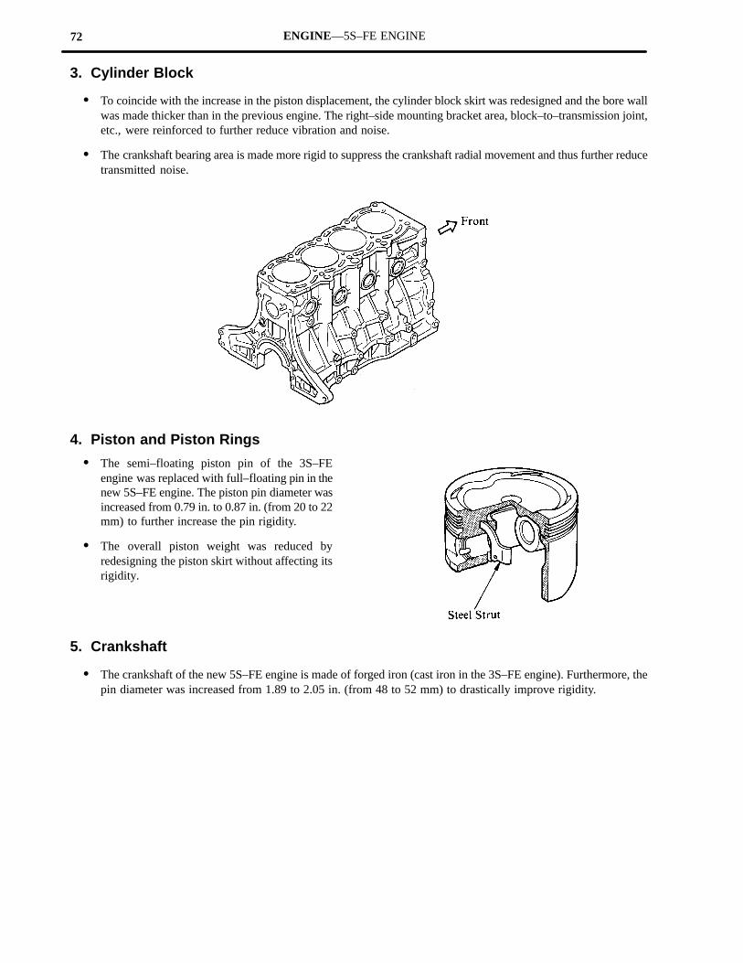
3. Cylinder Block
� To coincide with the increase in the piston displacement, the cylinder block skirt was redesigned and the bore wallwas made thicker than in the previous engine. The right–side mounting bracket area, block–to–transmission joint,etc., were reinforced to further reduce vibration and noise.
� The crankshaft bearing area is made more rigid to suppress the crankshaft radial movement and thus further reducetransmitted noise.
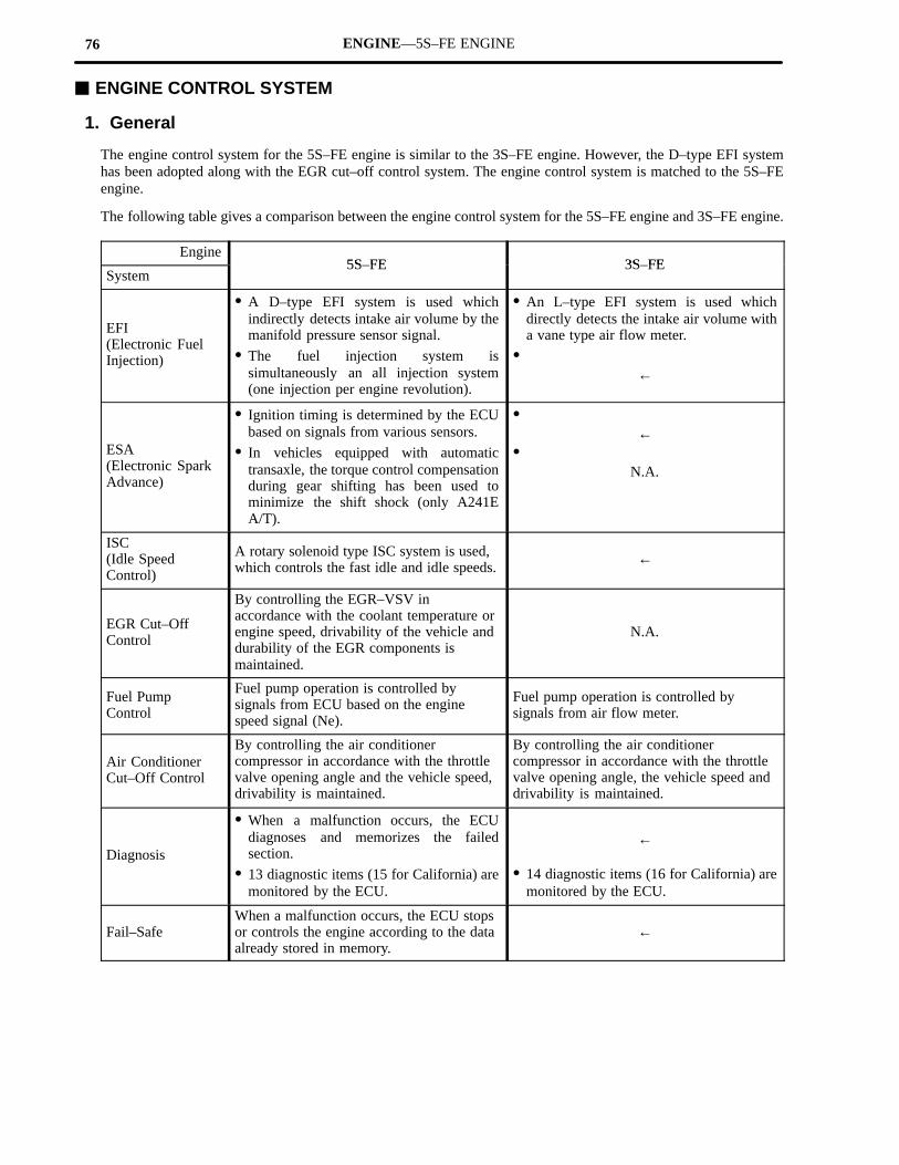
4. Piston and Piston Rings
� The semi–floating piston pin of the 3S–FEengine was replaced with full–floating pin in thenew 5S–FE engine. The piston pin diameter wasincreased from 0.79 in. to 0.87 in. (from 20 to 22mm) to further increase the pin rigidity.
� The overall piston weight was reduced byredesigning the piston skirt without affecting itsrigidity.
5. Crankshaft
� The crankshaft of the new 5S–FE engine is made of forged iron (cast iron in the 3S–FE engine). Furthermore, thepin diameter was increased from 1.89 to 2.05 in. (from 48 to 52 mm) to drastically improve rigidity.

73ENGINE—5S–FE ENGINE
6. Connecting Rod and Connecting Rod Bearings
� The connecting rod is hot–forged type.
� The connecting rod bearing cap is fastened withplastic region bolts.
� To coincide with the new connecting rod, theconnecting rod bearing is made of highlyheat–resistance kelmet alloy.
7. Flywheel
� The crankshaft is fastened by 8 bolts to furtherincrease reliability.
� VALVE MECHANISM
Valve Timing
The valve timing was changed as shown below to further improve performance.

74 ENGINE—5S–FE ENGINE
� LUBRICATION SYSTEM
Oil Cooler
An oil cooler is installed in the GT–S with manual transmission.
� COOLING SYSTEM
General
� The diameter of the thermostat was increased from 1.18 to 1.38 in. (from 30 to 35 mm) to more efficiently coolthe engine around the port area in the cylinder head and around spark plugs.
� The radiator tube design was changed to optimize flow and the fin shape was reviewed in order to further improvecooling performance and reduce the overall weight.
� INTAKE SYSTEM
Resonator
A resonator is fitted to the air intake hose to reduce intake air noise.

75ENGINE—5S–FE ENGINE
� ENGINE MOUNTING
1. General
� The new 5S–FE engine is mounted at four points the same as 3S–FE engine.
� A newly–developed, cylindrical, liquid–filled compound mount is used at the left and right sides to reduce theengine noise and vibration.
� The right–hand mounting bracket is made of aluminum to reduce weight and increase rigidity.
� A stay is added to left and right mounts and a dynamic damper is added to the right–hand mount to further reducevibration and noise.
2. Cylindrical Liquid–filled Compound Mount
The newly–developed, cylindrical, liquid–filled compound mount has an insulator filled with a fluid. The fluid insidethe fluid chamber reduces the dynamic spring modulus in the high–frequency range and thus increases quietness inthe passenger compartment. The flow of fluid through the orifice increases the damping coefficient and thussuppresses the engine vibration.
76 ENGINE—5S–FE ENGINE
� ENGINE CONTROL SYSTEM
1. General
The engine control system for the 5S–FE engine is similar to the 3S–FE engine. However, the D–type EFI systemhas been adopted along with the EGR cut–off control system. The engine control system is matched to the 5S–FEengine.
The following table gives a comparison between the engine control system for the 5S–FE engine and 3S–FE engine.
Engine5S FE 3S FE
System5S–FE 3S–FE
EFI(Electronic FuelInjection)
� A D–type EFI system is used whichindirectly detects intake air volume by themanifold pressure sensor signal.
� The fuel injection system issimultaneously an all injection system(one injection per engine revolution).
� An L–type EFI system is used whichdirectly detects the intake air volume witha vane type air flow meter.
�←
ESA(Electronic SparkAdvance)
� Ignition timing is determined by the ECUbased on signals from various sensors.
� In vehicles equipped with automatictransaxle, the torque control compensationduring gear shifting has been used tominimize the shift shock (only A241EA/T).
�←
�N.A.
ISC(Idle SpeedControl)
A rotary solenoid type ISC system is used,which controls the fast idle and idle speeds.
←
EGR Cut–OffControl
By controlling the EGR–VSV inaccordance with the coolant temperature orengine speed, drivability of the vehicle anddurability of the EGR components ismaintained.
N.A.
Fuel PumpControl
Fuel pump operation is controlled bysignals from ECU based on the enginespeed signal (Ne).
Fuel pump operation is controlled bysignals from air flow meter.
Air ConditionerCut–Off Control
By controlling the air conditionercompressor in accordance with the throttlevalve opening angle and the vehicle speed,drivability is maintained.
By controlling the air conditionercompressor in accordance with the throttlevalve opening angle, the vehicle speed anddrivability is maintained.
Diagnosis
� When a malfunction occurs, the ECUdiagnoses and memorizes the failedsection.
� 13 diagnostic items (15 for California) aremonitored by the ECU.
←
� 14 diagnostic items (16 for California) aremonitored by the ECU.
Fail–SafeWhen a malfunction occurs, the ECU stopsor controls the engine according to the dataalready stored in memory.
←

77ENGINE—5S–FE ENGINE
Engine control system for the 5S–FE engine has the following functions:
EFI (Electronic Fuel Injection)
The ECU determines the fuel injection duration according to the intake manifold pressure, engine speed, coolanttemperature and other signals, then sends control signals to the fuel injectors. The fuel injection duration is also thebasis for deciding the fuel injection timing. The fuel injection system is simultaneously an injection system.
ESA (Electronic Spark Advance)
The ECU determines the amount of ignition advance in addition to the initial timing based on the intake manifoldpressure, engine speed, coolant temperature and other signals, then sends control signals to the igniter.
In vehicles equipped with automatic transaxle the ignition timing is delayed in accordance with the shift positionsduring all shifting to control the engine output temporarily and reduce shift shock (only A241E A/T).
ISC (Idle Speed Control)
By means of engine speed signals, the ECU sends control signals to the ISC valve to maintain actual idle speed atthe target idle speed stored in the ECU. Also, while the engine is warming up, the ECU, based on coolant temperaturesignals, sends controls signals to the ISC value to increase engine speed to fast idle.
EGR Cut–Off Control
The ECU sends a signal to the EGR VSV to shut–off the EGR according to the coolant temperature, engine speedand intake manifold pressure. This helps to maintain drivability of the engine under cold temperature and at highengine rpm, and durability of EGR components.
Fuel Pump Control
Normally, the ECU controls the operation of the fuel pump based on the engine speed signal detected by thedistributor. While the engine is cranking, however, the ST signal from the ignition switch controls the fuel pump.
Air Conditioner Cut–Off Control
The ECU sends control signals to the air conditioner amplifier base don the throttle position, vehicle speed and airconditioner switch signals to shut–off the air conditioner compressor temporarily to maintain drivability while theair conditioner is operating.
Diagnosis
The ECU is constantly monitoring signals from each sensor. If trouble develops with the signals, the CHECKENGINE lamp inside the meter panel lights up and informs the driver of the malfunction. The contents of the troublecodes are stored in ECU memory and when the T and E1 terminals in the check connector are connected, the ECUoutputs the trouble code by flashing the CHECK ENGINE lamp.
Fail–Safe
If the ECU judges from the signals from each sensor that there is a malfunction, it will continue the engine operation,using its own data or it will stop the engine.

78 ENGINE—5S–FE ENGINE
2. Construction
The engine control system can be broadly divided into three groups; the sensors, the ECU and the actuators.
*1: Applicable only to A241E automatic transaxle models.*2: Applicable only to California specification vehicles.*3: Refer to page 115 for detail.
79 ENGINE—5S–FE ENGINE
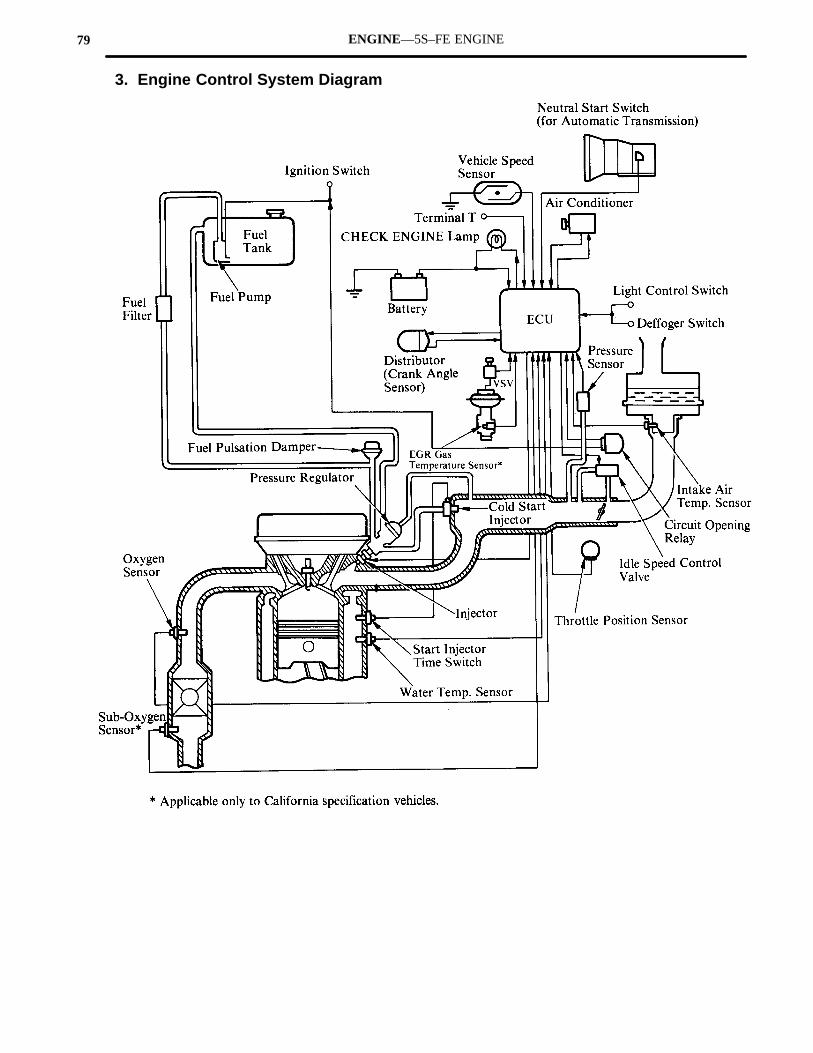
3. Engine Control System Diagram

80 ENGINE—5S–FE ENGINE
4. Arrangement of Engine Control System Components
81ENGINE—5S–FE ENGINE
5. Construction and Operation of Main Components
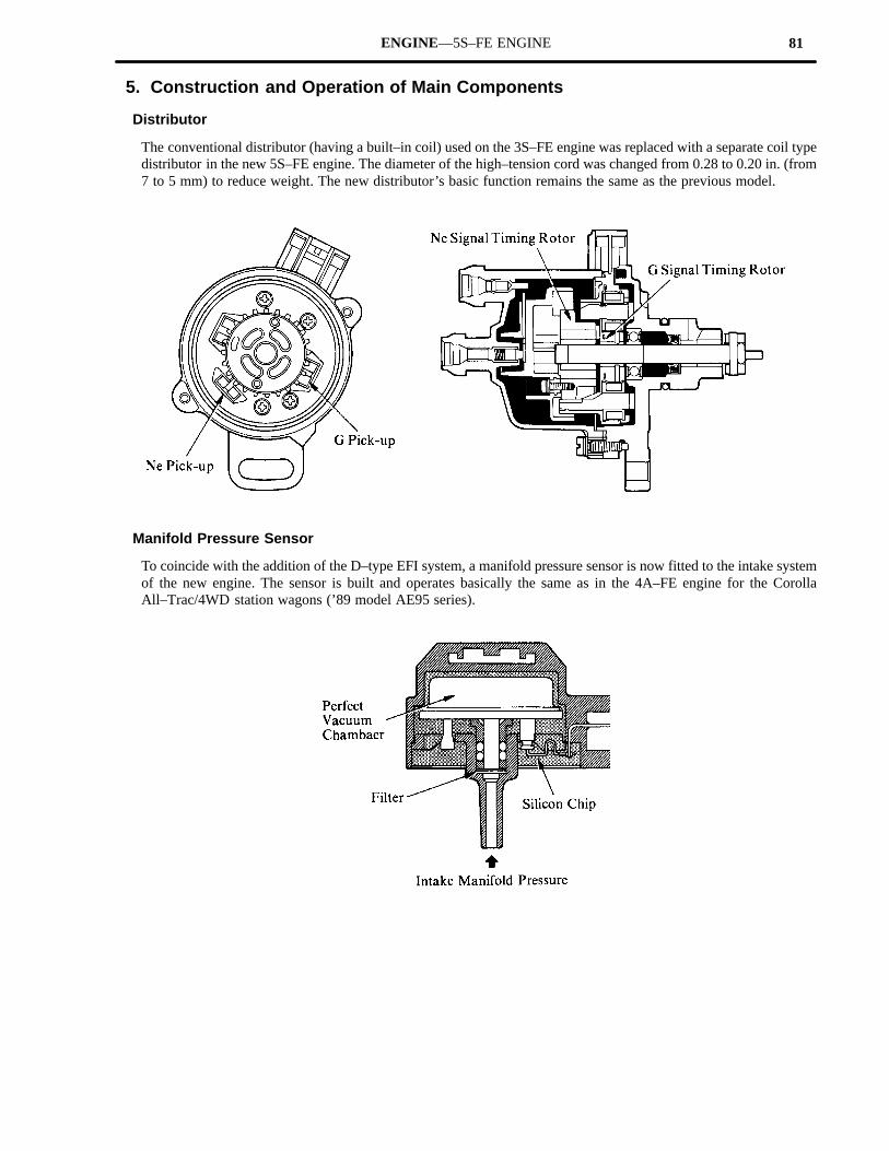
Distributor
The conventional distributor (having a built–in coil) used on the 3S–FE engine was replaced with a separate coil typedistributor in the new 5S–FE engine. The diameter of the high–tension cord was changed from 0.28 to 0.20 in. (from7 to 5 mm) to reduce weight. The new distributor’s basic function remains the same as the previous model.
Manifold Pressure Sensor
To coincide with the addition of the D–type EFI system, a manifold pressure sensor is now fitted to the intake systemof the new engine. The sensor is built and operates basically the same as in the 4A–FE engine for the CorollaAll–Trac/4WD station wagons (’89 model AE95 series).

82 ENGINE—5S–FE ENGINE
Throttle Position Sensor
Two types of throttle position sensors (point type and linear type) are used in the 5S–FE engine, and used selectivelyaccording to the transaxle type.
Transaxle Type Throttle Position Sensor
Manual Transaxle (S53)Point Type
Automatic Transaxle (A241L)Point Type
Automatic Transaxle (A241E) Linear Type
�Point Type�
�Linear Type�
83ENGINE—5S–FE ENGINE
6. EFI (Electronic Fuel Injection)
General
The EFI system consists of three sub–systems as in the 3S–FE engine; the fuel, air induction and electronic controlsub–systems. All of the three systems were modified to match the new 5S–FE engine.
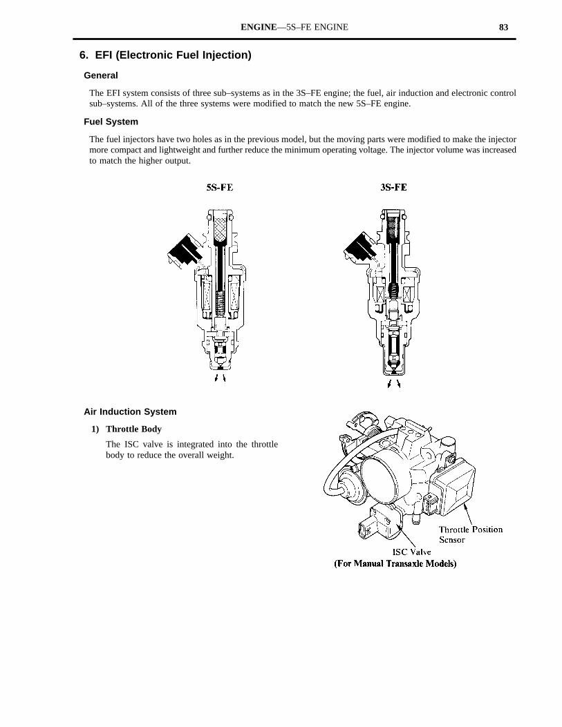
Fuel System
The fuel injectors have two holes as in the previous model, but the moving parts were modified to make the injectormore compact and lightweight and further reduce the minimum operating voltage. The injector volume was increasedto match the higher output.
Air Induction System
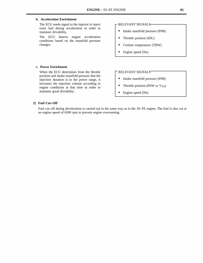
1) Throttle Body
The ISC valve is integrated into the throttlebody to reduce the overall weight.

84 ENGINE—5S–FE ENGINE
Electronic Control System
1) Injection Duration Control
The ECU determines the duration of each injection cycle in three steps as shown below, the same as in the 3S–FEengine.
Step 1: Determination of Basic Injection Duration
Step 2: Determination of Adjusted Injection Duration
Step 3: Determination of Length of Injection Signal
The EFI in the 5S–FE engine controls step three in the same way as the EFI in the 3S–FE engine, but due to theadoption of the D–type EFI system which uses a manifold pressure sensor, the methods of determining the “basicinjection duration” in Step 1, and or “acceleration enrichment” and “power enrichment” in Step 2, have beenchanged.
a. Basic Injection Duration Determined
The basic injection duration is determined by the manifold pressure (PIM signal) and the engine speed (Nesignal). The internal memory of the ECU contains data of various basic injection durations for various manifoldpressures and engine speeds.
85ENGINE—5S–FE ENGINE
b. Acceleration Enrichment
The ECU sends signal to the injector to injectextra fuel during acceleration in order tomaintain drivability.
The ECU detects engine accelerationconditions based on the manifold pressurechanges.
RELEVANT SIGNALS
� Intake manifold pressure (PIM)
� Throttle position (IDL)
� Coolant temperature (THW)
� Engine speed (Ne)
c. Power Enrichment
When the ECU determines from the throttleposition and intake manifold pressure that theinjection duration is in the power range, itincreases the injection volume according toengine conditions at that time in order tomaintain good drivability.
RELEVANT SIGNALS
� Intake manifold pressure (PIM)
� Throttle position (PSW or VTA)
� Engine speed (Ne)
2) Fuel Cut–Off
Fuel cut–off during deceleration is carried out in the same way as in the 3S–FE engine. The fuel is also cut atan engine speed of 6500 rpm to prevent engine overrunning.

86 ENGINE—5S–FE ENGINE
7. ESA (Electronic Spark Advance)
General
The principles of ignition timing control are the same as in the 3S–FE engine. However, with the adoption of theD–type EFI system, the method for calculating the basic ignition advance angle when the IDL contacts are open hasbeen changed.
Also, for vehicles equipped with A241E automatic transaxle, torque control compensation is added to minimize theshift shock when shifting.
Determination of Basic Ignition Advance Angle
The basic ignition advance angle when the IDL contacts are closed is determined by the ECU from the engine speed,same as in the 3S–FE engine. When the IDL contacts are open, the most appropriate basic ignition advance angleis selected by the ECU from basic ignition advance angle data stored in the ECU. This data is determined inaccordance with the engine speed and intake air volume in the case of the L–type EFI system in the 3S–FE engine,but in the D–type EFI system in the 5S–FE engine, it is determined in accordance with the engine speed and intakemanifold pressure.
�Basic Ignition Advance Angle Data�
RELEVANT SIGNALS
� Intake manifold pressure (PIM)
� Engine speed (Ne)
� Throttle position (IDL)
Torque Control Compensation During Shifting (Only A241E A/T)
In the case of vehicles equipped with A241E automatic transaxle, each clutch and brake of the planetary gear unitin the transaxle generates shock more or less during shifting. In the 5S–FE engine, this shock is minimized by delayingthe ignition timing when gears are shifted in the automatic transaxle.
The ECU judges the vehicle’s condition by engine speed and torque converter turbine runner speed, then determinesthe optimum amount of ignition timing delay from gear shifting mode (1→2, 2→3, 3→4, 4→3, 3→2, 2→1) and thethrottle valve opening angle.
This compensation is not performed at times whenthe coolant temperature is below 140°F (60°C),when the battery terminal voltage is below 8V, orwhen the No. 2 shift solenoid valve in the automatictransaxle is malfunctioning.
RELEVANT SIGNALS
� Engine speed (Ne)
� Vehicle speed (SP2)
� Throttle position (VTA)
� Coolant temperature (THW)
� Gear shift position (S1, S2)
� Battery (+B)

87ENGINE—5S–FE ENGINE
8. ISC (Idle Speed Control)
General
The rotary solenoid type ISC valve of the 3S–FE engine is retained for the 5S–FE engine. Although the basic valveconstruction and operation remain unchanged, a feedback control is added in the new engine for the air conditionerfeature and the valve is made more compact and lightweight.
Feedback Control During Air Conditioner Operation
When the ECU receives a signal from the airconditioner amplifier, it opens the ISC valve toincrease idle speed. At the same time, it beginsfeedback control at a target idle speed for airconditioner operation.
RELEVANT SIGNALS
� Engine speed (Ne)
� Throttle position (IDL)
� Vehicle speed (SPD)
� Coolant temperature (THW)
� Neutral start switch (NSW)
� Air conditioner switch (A/C)

88 ENGINE—5S–FE ENGINE
9. EGR Cut–Off Control
This system actuates the VSV to replace intake manifold vacuum acting on the EGR vacuum modulator withatmospheric air and thus shuts off the EGR.
Operation
The ECU actuates the VSV and cuts the EGR fromthe system when the coolant temperature is below140°F (60°C) or the engine speed is about 4400 rpmto maintain drivability. The ECU also actuates theVSV and cuts the EGR from the system when theintake manifold pressure is above a predeterminedlevel to maintain durability of the EGRcomponents.
10.Fuel Pump Control
See page 64 under 3S–GTE engine for detail.
11.Air Conditioner Cut–Off Control
See page 65 under 3S–GTE engine for detail.

89ENGINE—5S–FE ENGINE
12.Diagnosis
The diagnostic system in the new 5S–FE engine monitors thirteen conditions (fifteen for California) in the chartbelow. The purpose of this system is the same as for the current 3S–FE engine, but diagnostic items have been changedto match the 5S–FE engine.
Diagnostic Items
Code Item Diagnosis Trouble Area“CHECKENGINE”
CodeNo. Item Diagnosis Trouble Area ENGINE”
Lamp
12 RPM Signal No “Ne” or “G” signals to ECU within 2 seconds after the engine iscranked.
� Distributor circuit
� Distributor
� Starter signal circuit
� ECU
ON
13 RPM Signal No “Ne” signal to ECU when the engine speed is above 1000 rpm.
� Distributor circuit
� Distributor
� ECU
ON
14 Ignition Signal No “IGf” signal to ECU 4�5 times in succession.
� Igniter circuit
� Igniter
� ECU
ON
21 Oxygen SensorSignal
During air–fuel ratio feedback correction, voltage output from theoxygen sensor does not exceed a set value on the lean side and the richside continuously for a certain period.
� Oxygen sensor circuit
� Oxygen sensorON
22 Water Temp.Sensor Signal Open or short circuit in water temp. sensor signal (THW).
� Water temp. sensor circuit
� Water temp. sensor
� ECU
ON
24 Intake Air Temp.Sensor Signal Open or short circuit in intake air temp. sensor signal (THA).
� Intake air temp. sensor circuit
� Intake air temp. sensor
� ECU
ON*
25 Air–fuel RatioLean Malfunction 1)* When air–fuel ratio feedback correction value or adaptive control
value continues at the upper (lean) or lower (rich) limit for a certainperiod of time or adaptive control value is not renewed for a certainperiod of time.
2)* When marked variation is detected in engine revolutions for eachcylinder during idle switch on and feedback condition.
� Injector circuit
� Injector
� Fuel line pressure
� Oxygen sensor circuit
� Oxygen sensor
� Intake manifold pressure
� Water temp. sensor
� ECU
ON
ON*
26 Air–fuel RatioRich Malfunction
cylinder during idle switch on and feedback condition.
3) Open or short circuit in oxygen sensor signal.� Injector circuit
� Injector
� Intake manifold pressure
� Water temp. sensor
� ECU
ON*
27* Sub–OxygenSensor Signal
Open or short circuit in sub–oxygen sensor signal.
� Sub–oxygen sensor circuit
� Sub–oxygen sensor
� ECU
ON
31 ManifoldPressure SensorSignal
Open or short circuit in manifold pressure sensor signal.
� Manifold pressure sensor circuit
� Manifold pressure sensor
� ECU
ON
41 Throttle PositionSensor Signal
� Open or short circuit in throttle position sensor signal (VTA). → ForA241E A/T.
� The “IDL” and “PSW” signal are output simultaneously for severalseconds. → Except A241E A/T.
� Throttle position sensor circuit
� Throttle position sensor
� ECU
ON*
*: Applicable only to California specification vehicles.

90ENGINE—5S–FE ENGINE
Code Item Diagnosis Trouble Area“CHECKENGINE”
CodeNo. Item Diagnosis Trouble Area ENGINE”
Lamp
42 Vehicle SpeedSensor Signal
No “SP1” signal to ECU for 8 seconds when engine speed is between 2400rpm and 5000 rpm and coolant temp. is above 176°F (80°C), except whenracing the engine.
� No. 1 vehicle speed sensor circuit
� No. 1 vehicle speed sensor
� ECU
OFF
43 Starter Signal No “STA” signal to ECU until engine speed reaches 800 rpm with vehiclenot moving.
� Starter signal circuit
� Ignition switch, main relay circuit
� ECU
OFF
71* EGR SystemMalfunction
� EGR gas temp. below a predetermined level during EGR operation.
� Open circuit in EGR gas temp. sensor signal (THG).
� EGR system components
� EGR gas temp. sensor circuit
� EGR gas temp. sensor
� ECU
ON
51SwitchConditionSignal
No “IDL” signal or No “NSW” signal or “A/C” signal to ECU, with thecheck terminals T and E1 connected.
� A/C amplifier
� A/C switch circuit
� Neutral start switch circuit
� Neutral start switch
� Throttle position sensor circuit
� Throttle position sensor
� Accelerator pedal and cable
� ECU
OFF
*: Applicable only to California specification vehicles.
NOTE: � If two or more malfunctions are present at the same time, the lowest–numbered diagnostic code will bedisplayed first.
� All detected diagnostic codes, except 51, will be retained in memory by the ECU from the time of detectionuntil cancelled out.
� Once the malfunction is corrected, the “CHECK ENGINE” warning lamp will go out but the diagnosticcode(s) will remain stored in the ECU memory (except for code 51).
� After the malfunction is corrected, the diagnostic code is cleared by removing the EFI fuse for more than10 seconds with the ignition switch off.
13.Fail–Safe
The fail–safe function of the 3S–FE engine is also used in the new 5S–FE engine plus the following additionalfunction.
Manifold Pressure Sensor Malfunction
The air–fuel ratio deviated from normal if the signal from the pressure sensor is open or shorted, causing improperengine running. In this case, a back–up mode operates and maintains the ignition timing and fuel injection timingat fixed values to continue operation.

91 ENGINE—5S–FE ENGINE
� EMISSION CONTROL SYSTEM
1. System Purpose
System Abbreviation Purpose
Positive crankcase ventilation
Evaporative emission control
Exhaust gas recirculation
Three–way catalyst
Electronic fuel injection
PCV
EVAP
EGR
TWC
EFI
Reduces blow–by gas (HC)
Reduces evaporative HC
Reduces NOx
Reduces HC, CO and NOx
Regulates all engine conditions for reductionof exhaust emissions.
2. Component Layout and Schematic Drawing
*: Applicable only to California specification vehicles.


![TRAJECTORY SIMULATION AND OPTIMIZATION OF THE LAPCAT-MR2 … · MR2 Vehicle Overview The MR2 vehicle layout is a result of multiple iterative design optimizations [4]. The main driver](https://static.fdocuments.in/doc/165x107/5f93920561adec01d17a02c0/trajectory-simulation-and-optimization-of-the-lapcat-mr2-mr2-vehicle-overview-the.jpg)