Engine failure and forced landing involving Cessna 208B ...
46
ATSB Transport Safety Report Aviation Occurrence Investigation AO-2016-155 Final – 18 December 2020 Engine failure and forced landing involving Cessna 208B, VH-LNH 8 km north-west of Solomon Airport, Western Australia, on 16 November 2016
Transcript of Engine failure and forced landing involving Cessna 208B ...

ATSB Transport Safety Report Aviation Occurrence Investigation AO-2016-155 Final – 18 December 2020
Engine failure and forced landing involving Cessna 208B, VH-LNH 8 km north-west of Solomon Airport, Western Australia, on 16 November 2016

Released in accordance with section 25 of the Transport Safety Investigation Act 2003
Publishing information
Published by: Australian Transport Safety Bureau Postal address: PO Box 967, Civic Square ACT 2608 Office: 62 Northbourne Avenue Canberra, Australian Capital Territory 2601 Telephone: 1800 020 616, from overseas +61 2 6257 2463 (24 hours) Accident and incident notification: 1800 011 034 (24 hours) Email: [email protected] Internet: www.atsb.gov.au
© Commonwealth of Australia 2020
Ownership of intellectual property rights in this publication Unless otherwise noted, copyright (and any other intellectual property rights, if any) in this publication is owned by the Commonwealth of Australia.
Creative Commons licence With the exception of the Coat of Arms, ATSB logo, and photos and graphics in which a third party holds copyright, this publication is licensed under a Creative Commons Attribution 3.0 Australia licence.
Creative Commons Attribution 3.0 Australia Licence is a standard form license agreement that allows you to copy, distribute, transmit and adapt this publication provided that you attribute the work.
The ATSB’s preference is that you attribute this publication (and any material sourced from it) using the following wording: Source: Australian Transport Safety Bureau
Copyright in material obtained from other agencies, private individuals or organisations, belongs to those agencies, individuals or organisations. Where you want to use their material you will need to contact them directly. Addendum
Page Change Date

Safety summary What happened On the morning of 16 November 2016, a single-engine Cessna 208B aircraft, registered VH-LNH, operated by Aviair Pty Ltd, departed Solomon Airport, Western Australia on a charter flight to Karratha. On-board the aircraft were two flight crew and 11 passengers. Approximately 8 km from the airport, while climbing through an altitude of approximately 4,600 ft, the aircraft sustained an engine failure. The flight crew heard a loud bang and observed smoke billowing from the exhaust.
The flight crew elected to conduct an emergency landing on a nearby dirt road associated with the Solomon mine precinct. The landing was accomplished without injury to the occupants and the aircraft sustained only minor damage.
What the ATSB found The ATSB found that a compressor turbine blade from the Pratt & Whitney Canada (PWC) PT6A-114A engine developed fatigue cracking and fractured after approximately 1.8 hours of operation, leading to an in-flight engine failure and forced landing of the aircraft. A repaired compressor turbine vane ring that was fitted to the engine was identified by PWC to contain variations in aerofoil geometry. These variations likely led to an increase in vibratory stresses and the associated development of fatigue cracking and fracture of the compressor turbine blade.
From this and other recent occurrences, the investigation identified that PT6A-114A engines fitted with compressor turbine vane rings that had been repaired in accordance with the United States Federal Aviation Administration (FAA) approved repair scheme STI 72-50-254 had an increased likelihood of CMSX-6 single-crystal compressor turbine blade fracture and subsequent failure of the engine.
The ATSB also found that the flight crew’s handling of the engine failure and subsequent emergency landing reduced the risk of damage to the aircraft and/or injury to the passengers or crew.
What's been done as a result On 16 March 2017, the holder of the major repair specification for the compressor turbine vane ring, Southwest Turbine Inc. (STI), ceased conducting repairs on CT vane rings for fitment into PWC PT6A-114A engines.
On 29 March 2017, the engine manufacturer, PWC, released Service Instruction Letter (SIL) PT6A-252 to all operators of PT6A-114 and -114A engines. The SIL advised of the heightened risk of CMSX-6 single-crystal compressor turbine blade fatigue fracture when combined with a compressor turbine vane ring that had been repaired using processes that were not approved by PWC.
Pro-active safety action from the aircraft operator, Aviair Pty Ltd, included adopting the recommendations contained in PWC SIL PT6A-252. Their Cessna 208B fleet was reviewed, and any PT6A-114A engines containing compressor turbine vane rings that had been repaired using ‘non-PWC approved processes’, were replaced with CT vane rings produced by PWC.
On 19 August 2019, Transport Canada released airworthiness directive (AD) CF-2019-30 linking the low-time fatigue-fracture of CMSX-6 single-crystal compressor turbine blades and the use of CT vane rings that had been repaired in accordance with repair specification STI 72-50-254. The AD required operators to check for, and remove, STI-repaired CT vane rings from PT6A-114 and PT6A-34 series engines within a defined period of 9 calendar months, or 250 hours of operation.

The Civil Aviation Safety Authority automatically adopted AD CF-2019-30. This required Australian operators to remove STI-repaired compressor turbine vanes rings fitted to PT6A-114A and PT6A-34 series engines.
On 17 August 2020, the FAA released a Notice of Proposed Rulemaking advising that they were considering mandating AD CF-2019-030. Public submissions to that process closed on 1 October 2020.
The vibratory effect of repaired CT vane rings on CMSX-6 single-crystal CT blades within PWC PT6A-114A engines was identified as a safety issue by the ATSB. However, due to the significant safety action taken by the directly involved parties since the occurrence, including action from the engine and component manufacturers, as well as the aviation regulatory authorities, the ATSB considers that the risk of CMSX-6 single-crystal CT blade fractures in Australian-operated PWC PT6A-114A engines has been adequately addressed.
Safety message This occurrence shows how subtle changes can have a detrimental effect on modern complex turbine engines. In this instance, geometry variations in a repaired compressor turbine vane ring likely led to rapid fatigue cracking and fracture of a compressor turbine blade, and subsequent engine failure.
The incident also reinforces the importance of communication and effective decision-making during an emergency. The crew’s handling of the forced landing minimised the potential for injury or aircraft damage.
VH-LNH Cessna 208B aircraft
Source: Jim Woodrow
Contents
The occurrence ........................................................................................................................1 What happened 1
Context ......................................................................................................................................3 Recorded information 3
Engine data 3 Spidertracks 4 Emergency locator beacon 4 Flight data recorders 5
Meteorological information 5 Personnel information 5 Aircraft information 5
Engine failure procedure 5 Aircraft glide performance 6
Engine information 7 Engine disassembly 7
Significant engine maintenance 11 Component examination 12
Compressor turbine blade from the occurrence engine 12 Compressor turbine vane ring from the occurrence engine 15 PWC CT blade vibration measurement 17 CT vane ring from occurrence engine 18
Compressor turbine vane ring repair 18 Regulatory review of major repair specification STI 72-50-254 19 Data from Southwest Turbine Inc. 20
History of compressor turbine blade and related design changes 20 Inconel 100 compressor turbine blades 20 CMSX-6 single crystal compressor turbine blade development 21
Related compressor turbine blade failure occurrences 21 Certification 24 Safety analysis 24 Failure rates 24
PT6A-114A turbine blade and vane ring regulatory action 25 Replacement of IN100 blades with single-crystal CMSX-6 blades 25 Removal of repaired STI 72-50-254 CT vane rings 25
Safety analysis ...................................................................................................................... 27 Compressor turbine blade fracture 27 Compressor turbine vibratory stresses 27 Failure rates 28 Flight crew response 29
Findings ................................................................................................................................. 30 Contributing factors 30 Other findings 30
Safety issues and actions ................................................................................................... 31 General details ...................................................................................................................... 35
Occurrence details 35 Aircraft details 35

Sources and submissions .................................................................................................. 36 Sources of information 36 Submissions 36
Appendix A: Compressor turbine vane ring measurements ......................................... 37 Australian Transport Safety Bureau .................................................................................. 39
Purpose of safety investigations 39 Developing safety action 39 Terminology used in this report 40

› 1 ‹
ATSB – AO-2016-155
The occurrence What happened On 16 November 2016, at about 0630 Western Standard Time,1 a single-engine Cessna 208B aircraft, registered VH-LNH, departed Karratha Airport, Western Australia (WA) on a flight to Solomon Airport, WA. On board the aircraft were the pilot-in-command, a safety pilot, and 11 passengers. The flight was operated by Aviair as a charter2 service, transferring workers to and from the Solomon Hub, an iron-ore mining and processing facility in the Hamersley Ranges of northern WA.
At about 0710, after a 40-minute flight, the aircraft arrived at Solomon Airport. Following disembarkation at the terminal, the flight crew prepared the aircraft for the return flight with 11 passengers. The start-up and pre-flight checks for the return flight to Karratha were conducted without any reported issues. At 0740, the aircraft was taxied to runway 273 and about 3 minutes later, the flight departed for Karratha, initially conducting a left climbing turn overhead the Solomon Airport and then climbing on a north-westerly heading over the Hamersley Range (Figure 1).
A few minutes after taking off, while climbing through an altitude of approximately 4,600 ft above mean sea level (AMSL), the pilot-in-command reported hearing a ‘loud bang’ and ‘grinding noise’ from the engine followed by a decrease in aircraft performance. Blue and white smoke ‘billowed’ from the exhaust. Instruments within the cockpit showed rapidly reducing turbine speed and torque, indicating the aircraft’s engine had failed. At this point, the aircraft was about 8 km from the departure airport.
The pilot-in-command recalled lowering the aircraft’s nose to attain the recommended glide speed and reducing the engine power lever to idle as part of the initial checks. On commencing a right turn back toward the airport, the flight crew assessed that an emergency landing to the airport would not be possible. The aircraft would be gliding into a southerly head wind and given their altitude, it was uncertain whether they could safely avoid the high terrain between their current position and Solomon Airport.
Scanning the immediate area, the flight crew identified an unsealed dirt road as a potential emergency landing area. The road was oriented north-south and was near to an accommodation village associated with the mine construction. The pilot-in-command delegated the emergency calls to the safety pilot and concentrated on setting up for the forced landing. The safety pilot conducted the necessary actions to secure the engine further and communicate their situation. The fuel lever was set to cut-off and the propeller lever to feather.4 Suspecting that the aircraft was too low to communicate effectively with air traffic services, the safety pilot broadcast an emergency MAYDAY5 advising of their situation on the VHF common traffic advisory frequency for Solomon Airport. A departing Qantas aircraft detected the broadcast, along with Solomon Airport personnel who were monitoring the frequency. The safety pilot also activated the Spidertracks6 emergency notification system.
In preparation for the forced landing, the safety pilot provided an emergency passenger briefing.
1 Western Standard Time (WST): Coordinated Universal Time (UTC) + 8 hours. 2 Charter operations involve the carriage of passengers and/or cargo on non-scheduled flights by the aircraft operator,
for trade or commerce. 3 Runway number: the number represents the magnetic heading of the runway. 4 Propeller blades can automatically turn (or be intentionally turned) to a feathering angle, following engine failure or
malfunction, to minimise drag and prevent further damage. 5 MAYDAY: an internationally recognised radio call announcing a distress condition where an aircraft or its occupants are
being threatened by serious and/or imminent danger and the flight crew require immediate assistance. 6 Spidertracks is a satellite-based tracking system that includes an SOS function for use in an emergency.

› 2 ‹
ATSB – AO-2016-155
The pilot-in-command manoeuvred the aircraft for an approach to the mine road from the south. Full flap was selected about 1,000 ft above the terrain. The flight crew observed three vehicles travelling along the mine road close to their intended landing area. Approximately 100 ft above the road surface, the pilot flashed the aircraft’s landing lights to warn the driver of an approaching mine vehicle that the aircraft was preparing for an emergency landing. On touchdown, heavy braking was applied, slowing the aircraft until it came to a controlled stop about 150 m short of a bend in the road.
All passengers remained seated until instructed to exit the aircraft. The safety pilot moved the passengers away from the aircraft, while the pilot-in-command inspected for fire and other damage. Emergency responders from the airport arrived on scene shortly after. With the exception of some flat spots on the main gear tyres due to the emergency braking, the aircraft was undamaged. There were no injuries.
Figure 1: Sequence showing the aircraft departure from Solomon Airport, the pilot-reported location of the engine failure, and other events during the forced landing
Spidertracks aircraft location markers (identified green in the above image) are transmitted every 2 minutes under normal operation. When the SOS function is activated transmission signals are broadcast at 10-15 second intervals. Image source: Google, Maxar Technologies, annotated by the ATSB

› 3 ‹
ATSB – AO-2016-155
Context Recorded information Engine data The aircraft was equipped with an engine condition trend monitoring system. A range of parameters were automatically recorded by the system, including:
• pressure altitude • airspeed • engine torque • turbine temperature • gas generator speed • fuel flow • propeller shaft speed. The system was designed to assess engine performance by allowing an analyst to monitor recorded data over longer periods to identify emerging trends. It also recorded any turbine temperature or torque exceedances that can contribute to longer term degradation in engine performance. The system recorded flight data at approximately 0.5 second time intervals.
The data from the flight from Karratha to Solomon Airport, conducted earlier on the day of the occurrence showed no major deviations or ‘events’, generated from an inter-turbine temperature exceedance, gas generator overspeed or fuel flow anomaly. Data from the monitoring system also indicated normal operation of the engine up to the point of failure.
The recorded data from the occurrence flight is plotted in Figure 2. Following departure, the aircraft was climbing at an indicated airspeed of 106 kt when at 4,615 ft AMSL and time 0747:47, the engine failed. This was represented in the data by a rapid decline in the measured parameters for torque, propeller shaft speed, fuel flow and gas generator speed. The pilot’s report of sudden loud noises from the engine were consistent with the abrupt variation in the recorded parameters.
Eight seconds after the initial reduction in engine parameters, torque and fuel flow had reduced to zero, correlating with the pilot’s recollection of the events immediately following the failure. At 0750:17, the aircraft had descended to 4,200 ft AMSL and the recorded propeller speed had reduced to zero. After the failure, the inter-turbine temperature rapidly increased from 715 °C, peaking at 887 °C, before steadily declining as the failed engine cooled. Twenty-nine seconds after the engine failed, the gas generator speed had reduced from 99.5 per cent to zero. Changes to the indicated airspeed and altitude identified that touchdown on the mine road occurred at 0751:09 at an airspeed of approximately 80 kt.

› 4 ‹
ATSB – AO-2016-155
Figure 2: Presentation of the recorded data from the occurrence flight noting that the engine failure occurred at 0747:57 and the touchdown occurred at 07:51:09
Inter-turbine temperature, gas generator speed, indicated air speed, pressure altitude, propeller shaft speed, torque and fuel flow are plotted. The data is presented 4 minutes after take-off until the emergency landing. Image source: ATSB
Spidertracks The aircraft was equipped with a Spidertracks tracking and communication system. The system was satellite-based and sent a position update for the aircraft every 2 minutes. This allowed Aviair to monitor the progress of the aircraft in near real-time. An ‘SOS’ button on the keypad of the system could be activated by the flight crew. In the event the ‘SOS’ function was activated, the fidelity of the flight track was improved by transmitting a data point at 10-15 second intervals.
Data from the Spidertracks system showed that the aircraft was tracking to the north-west when the engine failure occurred. Two ‘SOS’ pings were transmitted by the system late in the sequence, shortly before touchdown on the mine road, however, these transmissions did not continue at the expected 10-15 second intervals for the remainder of the flight and landing. Spidertracks advised the ATSB that the unit on board the aircraft sustained a power shutdown shortly after the SOS signals were emitted. No further information was available to explain the signal loss during the emergency broadcast.
Emergency locator beacon The flight crew did not activate the emergency locator transmitter (ELT) during the emergency. The ELT was a radio beacon that, once activated, could assist search and rescue operations locate the aircraft and its occupants.
The Australian search and rescue authorities provide the following advice7 for pilots in relation to the use of an ELT during an emergency:
7 Australian Maritime Safety Authority, 2019, www.amsa.gov.au/safety-navigation/search-and-rescue/aviation
› 5 ‹
ATSB – AO-2016-155
When in the air, a beacon can be activated if you feel you are in grave and imminent danger. Facing a forced landing would be a reason to feel in grave and imminent danger. In a forced landing situation, when you are unsure of your position, when you are lost or have deviated from the planned or notified flight route, you should activate your distress beacon.
During this emergency, the flight crew of VH-LNH were in two-way radio communication with Solomon Airport authorities along with other commercial aircraft. The Spidertracks SOS alert had also been activated. These measures provided the flight crew with a level of assurance that an appropriate response was being provided. Had the emergency occurred later in the flight, in a remote area without access to a suitable landing area, in-flight activation of the ELT would likely have assisted any search and rescue operation identify the aircraft position and its occupants.
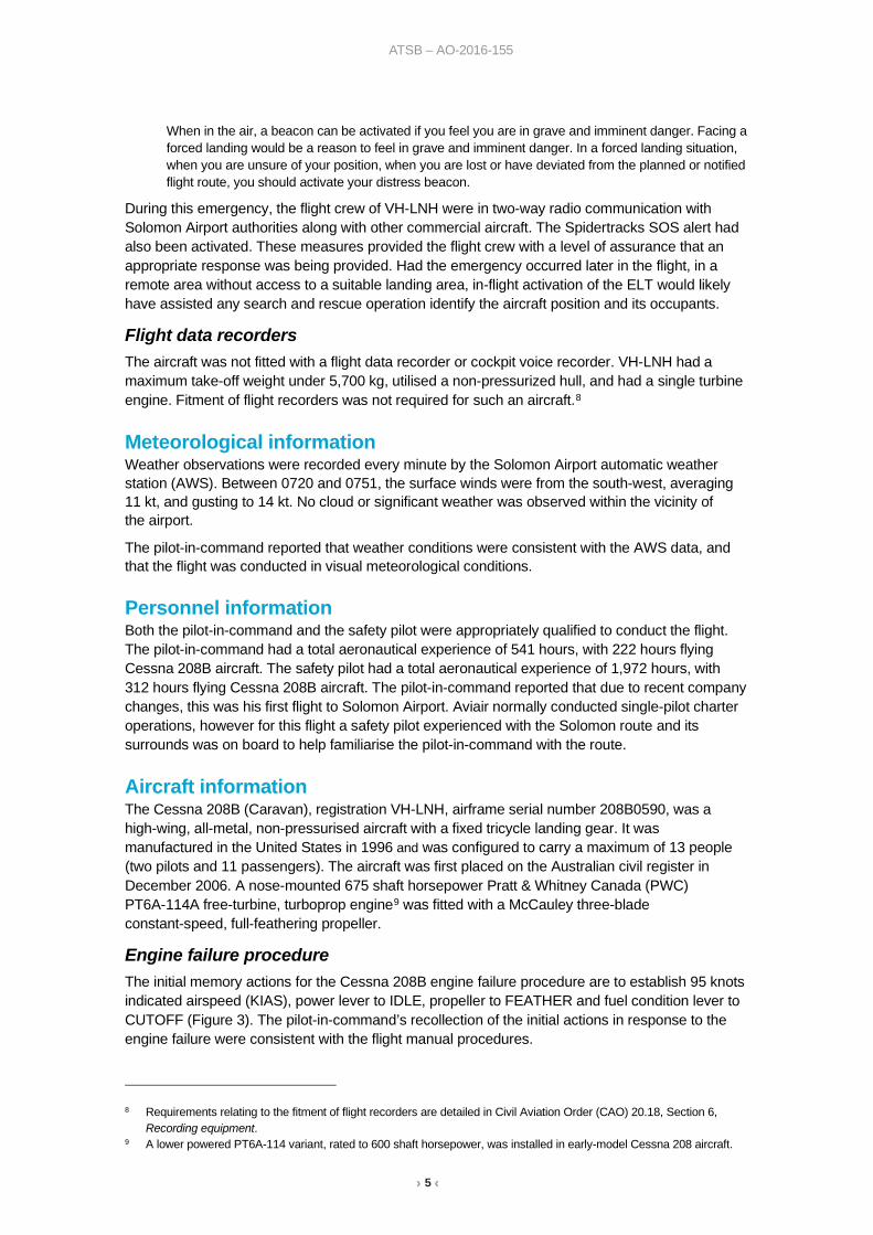
Flight data recorders The aircraft was not fitted with a flight data recorder or cockpit voice recorder. VH-LNH had a maximum take-off weight under 5,700 kg, utilised a non-pressurized hull, and had a single turbine engine. Fitment of flight recorders was not required for such an aircraft.8
Meteorological information Weather observations were recorded every minute by the Solomon Airport automatic weather station (AWS). Between 0720 and 0751, the surface winds were from the south-west, averaging 11 kt, and gusting to 14 kt. No cloud or significant weather was observed within the vicinity of the airport.
The pilot-in-command reported that weather conditions were consistent with the AWS data, and that the flight was conducted in visual meteorological conditions.
Personnel information Both the pilot-in-command and the safety pilot were appropriately qualified to conduct the flight. The pilot-in-command had a total aeronautical experience of 541 hours, with 222 hours flying Cessna 208B aircraft. The safety pilot had a total aeronautical experience of 1,972 hours, with 312 hours flying Cessna 208B aircraft. The pilot-in-command reported that due to recent company changes, this was his first flight to Solomon Airport. Aviair normally conducted single-pilot charter operations, however for this flight a safety pilot experienced with the Solomon route and its surrounds was on board to help familiarise the pilot-in-command with the route.
Aircraft information The Cessna 208B (Caravan), registration VH-LNH, airframe serial number 208B0590, was a high-wing, all-metal, non-pressurised aircraft with a fixed tricycle landing gear. It was manufactured in the United States in 1996 and was configured to carry a maximum of 13 people (two pilots and 11 passengers). The aircraft was first placed on the Australian civil register in December 2006. A nose-mounted 675 shaft horsepower Pratt & Whitney Canada (PWC) PT6A-114A free-turbine, turboprop engine9 was fitted with a McCauley three-blade constant-speed, full-feathering propeller.
Engine failure procedure The initial memory actions for the Cessna 208B engine failure procedure are to establish 95 knots indicated airspeed (KIAS), power lever to IDLE, propeller to FEATHER and fuel condition lever to CUTOFF (Figure 3). The pilot-in-command’s recollection of the initial actions in response to the engine failure were consistent with the flight manual procedures.
8 Requirements relating to the fitment of flight recorders are detailed in Civil Aviation Order (CAO) 20.18, Section 6,
Recording equipment. 9 A lower powered PT6A-114 variant, rated to 600 shaft horsepower, was installed in early-model Cessna 208 aircraft.

› 6 ‹
ATSB – AO-2016-155
Figure 3: Cessna 208B initial items for the engine failure procedure
Image source: Cessna - Textron Aviation
Aircraft glide performance The aircraft was at an altitude of approximately 4,600 ft AMSL and Solomon Airport was about 8 km (4.3 NM) to the south-east when the engine failed. The airport is at an elevation of 2,000 ft AMSL, indicating the aircraft was approximately 2,600 ft above the airport elevation when the engine failed. Taking into account an approximate 600 ft height loss due to the initial right turn towards the airport, the flight crew probably had an allowance of about 2,000 ft above the airport elevation when assessing the available landing options.
VH-LNH was configured with a cargo pod, which resulted in a glide range of 4 NM at 2,000 ft above the airport elevation. The best glide speed at the maximum weight is 95 KIAS, and 80 KIAS for a power-off landing speed with full flap. The airspeeds recorded by the engine-recording module were consistent with these figures.
A graph of the Cessna 208B glide performance from the pilot operating manual is depicted at Figure 4. Calculations indicated that, based on the published data, it might have been possible for the aircraft to reach the airport in a glide on a direct track in nil wind conditions. However, given the south-westerly wind would have resulted in a headwind component, it was unlikely the aircraft would have reached the airport. The crew also considered that an attempt to reach the airport presented an unnecessary risk of a forced landing on unprepared ground in rugged terrain, and instead they opted to conduct the forced landing on the mine road.
Figure 4: Cessna 208B maximum glide range with the glide distance highlighted
Image source: Cessna - Textron Aviation, annotated by ATSB
› 7 ‹
ATSB – AO-2016-155
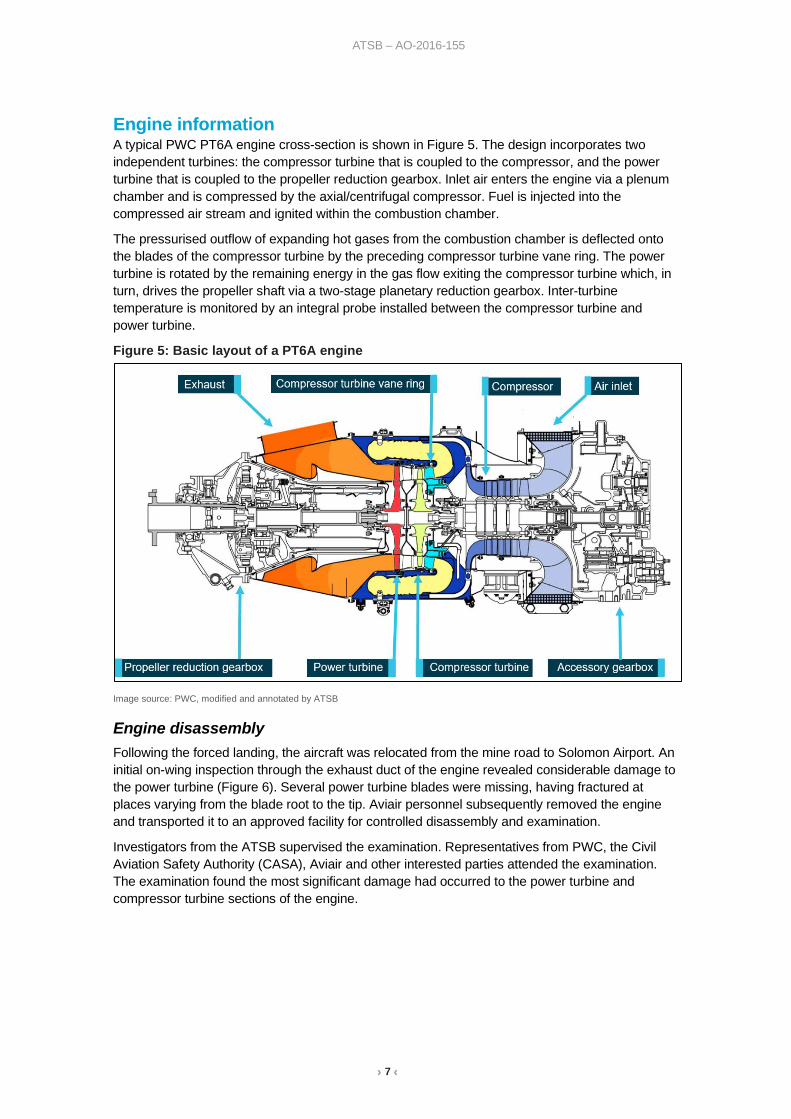
Engine information A typical PWC PT6A engine cross-section is shown in Figure 5. The design incorporates two independent turbines: the compressor turbine that is coupled to the compressor, and the power turbine that is coupled to the propeller reduction gearbox. Inlet air enters the engine via a plenum chamber and is compressed by the axial/centrifugal compressor. Fuel is injected into the compressed air stream and ignited within the combustion chamber.
The pressurised outflow of expanding hot gases from the combustion chamber is deflected onto the blades of the compressor turbine by the preceding compressor turbine vane ring. The power turbine is rotated by the remaining energy in the gas flow exiting the compressor turbine which, in turn, drives the propeller shaft via a two-stage planetary reduction gearbox. Inter-turbine temperature is monitored by an integral probe installed between the compressor turbine and power turbine.
Figure 5: Basic layout of a PT6A engine
Image source: PWC, modified and annotated by ATSB
Engine disassembly Following the forced landing, the aircraft was relocated from the mine road to Solomon Airport. An initial on-wing inspection through the exhaust duct of the engine revealed considerable damage to the power turbine (Figure 6). Several power turbine blades were missing, having fractured at places varying from the blade root to the tip. Aviair personnel subsequently removed the engine and transported it to an approved facility for controlled disassembly and examination.
Investigators from the ATSB supervised the examination. Representatives from PWC, the Civil Aviation Safety Authority (CASA), Aviair and other interested parties attended the examination. The examination found the most significant damage had occurred to the power turbine and compressor turbine sections of the engine.

› 8 ‹
ATSB – AO-2016-155
Figure 6: Composite image displaying the observed damage to the power turbine (left) and compressor turbine (right) displaying the missing aerofoil section.
Image source: ATSB
Compressor
Inspection of the compressor section identified that it was relatively undamaged, and the rotor assembly was free to rotate. Slight tip rub to the compressor blades had occurred. There was no evidence of foreign object damage.
Power turbine
The power turbine had sustained the most severe damage, with several blades having fractured due to overstress at varying heights between the blade root and the tip due to contact with upstream10 debris (Figure 6). The upstream face of the power turbine inlet guide vane had sustained significant hard-body impact damage, most likely from metallic debris released from the compressor turbine. The power turbine was seized and not able to rotate freely. The propeller shaft was also unable to be rotated.
Compressor turbine
Examination of the compressor turbine (CT) identified that a single CT blade had fractured close to the blade root (Figure 7 and 8). Multiple blades had sustained bending from impact damage with the liberated aerofoil section. One of the adjacent blades displayed a clear imprint from contact with the liberated aerofoil section (Figure 9). The fracture surface of the failed blade was largely flat and located at the root, close to the platform. Characteristic ‘beach mark’ features were present that extended to approximately 50 per cent of the overall fracture surface, indicating that a fatigue crack had progressed through that portion of the blade. The remainder of the fracture was jagged and angular and representative of a sudden overstress fracture.
Manufacturing identifiers on the fractured blade base confirmed it to be a PWC component:
• 3079351-01 (part number)• HWB5PL (serial number)• 702055 (vendor supplier)
10 Because the internal mechanical architecture of the PT6 engine is of a reverse and folded configuration, and the installed orientation of the PT6 engine is reversed, directional and positional designators such as ‘forward’ and ‘rear’ are ambiguous. The more accurate designator of ‘upstream’ and ‘downstream’ with respect to the engine’s internal airflow is used when describing internal parts. Installed orientation of external engine components are referenced with respect to the airframe.

› 9 ‹
ATSB – AO-2016-155
Aside from the missing aerofoil section from one of the CT blades, the engine disassembly did not reveal any other anomalies with respect to the CT disc and its installation.
Figure 7: The fractured CT blade
Fractured blade manufacturing identifiers; part number 3079351-01, serial number HWB5PL, vendor supplier 702055 Image source: ATSB
Figure 8: Close view of the the CT blade fracture surface
Image source: ATSB

› 10 ‹
ATSB – AO-2016-155
Figure 9: Composite view of a CT blade adjacent to the one that had fractured showing the collision imprint from the liberated aerofoil section
An exemplar blade (right image) from the disc has been used to illustrate the collision of the liberated aerofoil section from the fractured blade.Image source: ATSB
Compressor turbine vane ring
The CT vane ring fitted to the engine was also examined (Figure 10). The vanes had sustained abrasion and minor impact damage. The shroud segments had sustained two major gouges from the engine failure. The following manufacturing part numbers were identified:
• P/N 3029051 (part number) • S/N 931E (serial number) • WO 0452R16 CL 6.25 • STI 72-50-254 (authorised repair number) • STI 02-0356 Figure 10: Compressor turbine vane ring assembly, view of the downstream face with gouge damage (labelled)
CT vane ring manufacturing identifiers: (part number) 3029051, (serial number) 931E, (work order) WO 0452R16, (flow class) CL 6.25, (major repair specification) STI 72-50-254, (repair authority) STI 02-0356 Image source: ATSB

› 11 ‹
ATSB – AO-2016-155
Oil system
The magnetic chip detectors for the reduction and accessory gearboxes, as well as the oil filter were removed from the engine and inspected. A large amount of metallic debris had accumulated on the magnetic poles of each detector. Metallic debris was also present in the oil and oil filter.
Significant engine maintenance The engine, serial number PCE-17404, had accumulated 9,210.1 hours and 12,375 cycles since new, and 1,001.3 hours and 1,057 cycles since the last overhaul. This was within PWC’s normal recommendation of 3,600 hours between overhauls.
Airworthiness Directive (AD) CF-2013-21R1 Compressor Turbine Blade Failures was complied with on 15 November 2016. The AD required the existing compressor turbine (CT) blades11 manufactured from IN100 material to be replaced with PWC blades manufactured from CMSX-6, a single-crystal nickel-based superalloy.12
Records confirmed that the replacement CT blade set had a Transport Canada authorised release certificate from PWC. The part number of those blades was 3079351-01, indicating they were a single-crystal blade-type intended for use in this application and were the blades specified in AD CF-2013-21R1.
Due to the identification of converging cracks on the inner portion of the CT vane ring during maintenance inspection, the CT vane ring assembly was replaced. A release certificate authorised by the United States Federal Aviation Administration (FAA) accompanied the replacement CT vane ring. The certificate showed that the replacement vane ring, part number 3029051, serial number 931E, was repaired by Southwest Turbine Inc. in accordance with major repair specification STI 72-50-254.
The CT disc assembly and CT vane ring were provided by a Brisbane-based facility authorised to repair and overhaul PT6 engines. The parts were transferred to Karratha, where they were installed into the engine by an approved maintenance organisation. Following reassembly of the engine, records indicated that all required parameters of torque, inter-turbine temperature, fuel flow, gas generator and propeller speeds were met during power assurance testing.
During ground operation following the reassembly, a ‘whistling’ noise was identified when the gas generator speed was less than 60 per cent. A borescope inspection of the engine CT section along with a check of the bleed valve was performed, with no faults found. The engine operated for an additional 1.8 hours and two engine start-stop cycles before the CT blade fracture occurred. The recent maintenance activity is summarised in Table 1.
11 IN100 compressor turbine blades were PWC part number 3102401-01. 12 CMSX-6 compressor turbine blades were PWC part number 3079351-01.

› 12 ‹
ATSB – AO-2016-155
Table 1: Recent significant maintenance items for engine serial number PCE-17404 Date and location
Engine hours / cycles since overhaul
Maintenance / inspections completed
1 November 2016 Karratha
Time: 1,001.3 hrs Cycles: 1,057
Compliance with Airworthiness Directive CF-2013-21 R1 required CT disc removed and blades removed CT vane ring found to contain cracks
10 November 2016 Brisbane
Time: 1,001.3 hrs Cycles: 1,057
CT disc inspected and 58 x new PWC single-crystal CT blades (PN 3079351-01) installed. CT disc is assembled and balanced Repaired CT vane ring (PN 3029051, SN 931E) prepared for installation
15 November 2016 Karratha
Time: 1,001.3 hrs Cycles: 1,057
Airworthiness Directive CF-2013-21 R1 completed Installation of CT disc and single-crystal CT blades Repaired CT vane ring (PN 3029051, SN 931E) installed
15 November 2016 Karratha
Time: 1,001.3 hrs Cycles: 1,057
Engine ground performance run and acceleration checks carried out. Minor fault finding for noise below 60 % Ng with no issues found Aircraft returned to service
16 November 2016
Time: 1,003.1 hrs Cycles: 1,059
Engine failure on departure from Solomon Airport ~1.8 hours after CT blade replacement
Component examination Following this occurrence, the CT disc, blades and vane ring from the engine were sent to the Pratt & Whitney Canada (PWC) facilities in Montreal for detailed examination. An Accredited Representative13 from the Transportation Safety Board of Canada assisted the ATSB by providing oversight of the examination.
Compressor turbine blade from the occurrence engine The PWC metallurgical investigation confirmed that the engine failure was initiated by the fracture of a single compressor turbine (CT) blade. Fracture and release of the CT blade aerofoil section into the gas path led to many of the surrounding CT blades sustaining tip-bending and abrasion from rubbing against the CT shroud segments. Major downstream damage to the power turbine resulted from the blade release. Other CT blades exhibited secondary damage in the form of random nicks, cracks, bending and indentations from repeated impact against the liberated debris.
The fractured blade exhibited a very flat and smooth fracture surface at the leading edge, with features characteristic of fatigue crack propagation. The fracture plane was located at the platform-to-blade radial transition. Crack arrest features, or ‘beach marks’, were also clearly defined on the fracture surface, confirming the progressive growth of the fatigue crack through the blade section (Figure 11).
13 International Civil Aviation Aircraft Organisation, Annex 13 Aircraft Accident and incident Investigations: A person
designated by a State, on the basis of his or her qualifications, for the purpose of participating in an investigation conducted by another State.

› 13 ‹
ATSB – AO-2016-155
Figure 11: High-magnification optical image of the fractured blade showing that cracking initiated at the leading edge on the suction face, progressing through approximately 50 per cent of the cross-section prior to overstress fracture and release of the aerofoil
Image source: ATSB
Scanning electron microscopy
PWC’s examination of the fracture surface using a scanning electron microscope (SEM) further confirmed that the fatigue crack initiated from the blade-coating’s inter-diffusion layer at the leading edge surface (Figure 12). River lines on the fracture surface indicated that the fatigue crack had initiated from several sites along the leading edge of the blade. No evidence of anomalies such as coating defects or impact damage were noted at the fatigue crack initiation site. The crack initiation site was not associated with the blade casting parting line.
The SEM examination did not identify any defective features within the nickel-base alloy or coating material that might otherwise have led to the cracking.

› 14 ‹
ATSB – AO-2016-155
Figure 12: High-magnification SEM image of the crack origin at the leading edge showing the direction of propagation ‘river lines’ and other features associated with the blade coating
Image source: Pratt & Whitney Canada, annotated by ATSB
PWC reported that a semi-quantitative analysis of the fractured blade base material was performed using energy-dispersive spectroscopy, which confirmed that the blade material met the chemical requirements for CMSX-6, the alloy-type specified for use as the base blade material. The material analysis and part number identification 3079351-01 were coincident with the blade being manufactured from a CMSX-6 alloy, with a platinum-aluminide outer coating, as specified.
Metallurgical examination
PWC’s destructive cross-sectioning of the CT blade through the fatigue initiation zone did not reveal any metallurgical anomalies in this region. The microstructure of the fractured blade exhibited uniform cuboidal gamma / gamma-prime14 with no evidence of heat alteration. The microstructural examination identified some patches of secondary reaction zone15 underneath the blade coating. They were not, however, associated with the fatigue crack initiation site and PWC did not consider them to be contributory to the fatigue crack development. A cross-section through the aerofoil of an adjacent blade from the CT disc did not identify evidence of heat alteration to the blade microstructure. There was no report of micro-cracking of the blade coating in the region of the fatigue origin.
PWC concluded that there were no material anomalies identified on the remnant CT blade that might otherwise have initiated the fatigue cracking. The ATSB subsequently reviewed the physical evidence in detail, examining the remnants of the fractured blade using an optical microscope and SEM (Figure 13). Although some patches of altered microstructure were identified underneath the
14 Gamma / Gamma-prime (ɣ / ɣ’) is a microstructural constituent found in nickel-base heat-resistant alloys, which
provides an enhanced creep resistance and strengthening effect when distributed as a fine precipitate. 15 A secondary reaction zone is a microstructural instability in nickel-base superalloys that may develop beneath the blade
coating leading to reduced rupture strength and as a potential crack initiation site.

› 15 ‹
ATSB – AO-2016-155
blade coating, the patches were unlikely to have affected the crack initiation. After examining the CT blades and disc from the occurrence engine, and reviewing the PWC metallurgical report, the ATSB agreed with PWC’s findings in respect of the fractured CT blade.
Figure 13: Composite optical and SEM micrograph of the remnant fractured CT blade
The main SEM image is a cross-section through the crack origin. The primary microstructural features are described. Some alteration of the microstructure was observed with the formation of secondary reaction zone (SRZ) between the gamma / gamma -prime (ɣ / ɣ’) base microstructure and the blade coating. Image source: ATSB
Compressor turbine vane ring from the occurrence engine The CT vane ring fitted to the occurrence engine had the identifier STI 72-50-254. The identifying markings showed that the CT vane had been repaired by Southwest Turbine Inc. (STI), a supplier of components to the aviation gas turbine industry. The repair was performed under an approval granted by the FAA.
The CT vane ring from the occurrence engine was examined in the PWC Airfoil Laboratory and compared against the specifications for a PWC-manufactured vane ring16 for the PT6A-114A engine. STI did not participate in the inspection of the compressor turbine vane ring. PWC reported that notable differences existed between the STI-repaired vane ring and the
16 Pratt & Whitney Canada compressor turbine vane ring, part number 3029051
› 16 ‹
ATSB – AO-2016-155
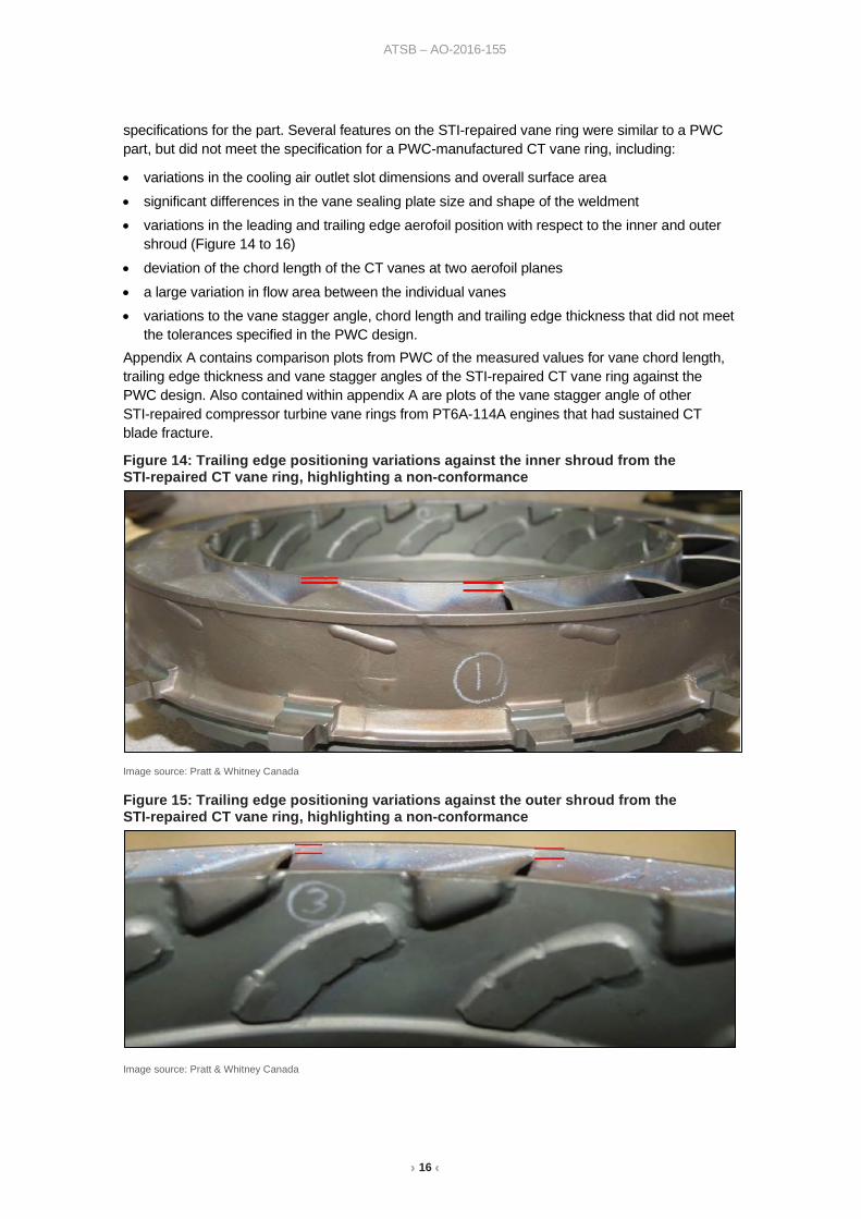
specifications for the part. Several features on the STI-repaired vane ring were similar to a PWC part, but did not meet the specification for a PWC-manufactured CT vane ring, including:
• variations in the cooling air outlet slot dimensions and overall surface area • significant differences in the vane sealing plate size and shape of the weldment • variations in the leading and trailing edge aerofoil position with respect to the inner and outer
shroud (Figure 14 to 16) • deviation of the chord length of the CT vanes at two aerofoil planes • a large variation in flow area between the individual vanes • variations to the vane stagger angle, chord length and trailing edge thickness that did not meet
the tolerances specified in the PWC design. Appendix A contains comparison plots from PWC of the measured values for vane chord length, trailing edge thickness and vane stagger angles of the STI-repaired CT vane ring against the PWC design. Also contained within appendix A are plots of the vane stagger angle of other STI-repaired compressor turbine vane rings from PT6A-114A engines that had sustained CT blade fracture.
Figure 14: Trailing edge positioning variations against the inner shroud from the STI-repaired CT vane ring, highlighting a non-conformance
Image source: Pratt & Whitney Canada
Figure 15: Trailing edge positioning variations against the outer shroud from the STI-repaired CT vane ring, highlighting a non-conformance
Image source: Pratt & Whitney Canada

› 17 ‹
ATSB – AO-2016-155
Figure 16: Example of trailing edge positioning against the outer shroud from a PWC-manufactured CT vane ring
Notable differences in vane positioning exist when compared with the STI-repaired item from the occurrence engine. Image source: Pratt & Whitney Canada
PWC CT blade vibration measurement PWC reported to the ATSB that during development of both the IN100 and CMSX-6 compressor turbine blades, the blade vibration characteristics were studied at various engine shaft speeds. A Mode-1 vibration, otherwise known as a fundamental frequency vibration, was identified as affecting the CMSX-6 blades. This increased the amplitude of aerofoil cyclic flexure, in turn, increasing stresses at the blade root.
PWC further reported that a resonant sub-harmonic of the Mode-1 vibration could excite the CT blades. Identified as the ‘Mode-1 7E’ (seventh excitation), PWC advised that it is driven by aerodynamic buffeting from the upstream combustor, which results in a pattern of non-uniform airflow around the CT disc. Different CT vane geometries and relative positioning can lead to buffeting of the CT blades from the upstream airflow and were reported to be a major contributor to the Mode-1 7E excitation.
PWC advised the ATSB that, following the development and release from production of the single-crystal CMSX-6 CT blades, a method was developed to evaluate the vibration experienced by the CT blades in PT6A-114A test engines. The method was a ‘non-contact strain measurement system’ (NSMS) and was intended to help manage high-cycle fatigue by identifying the vibratory conditions that might influence the fatigue life of the CT blades.
In basic terms, the NSMS testing utilised a laser-sensor arrangement to measure in-situ tip timing of each passing blade. The return signal from the time lag of each blade tip was analysed to assess the significance of aerofoil deflections, or the vibratory response of the blade, during engine operation.
PWC reported to the ATSB that their NSMS test program evaluated the effects of fuel nozzle variation, CT vane ring ‘clocking’ (or angular positioning), axial clearance, and new versus used engine hardware. In total, their NSMS testing involved 24 engine builds using different hardware and varying configurations. The testing indicated that the dynamic response (vibration) of the CT blades could be reduced by controlling variables such as:
• the inter-platform gap between respective blades • CT blade trailing edge thickness • the relative position of the vane (clocking) • under-platform blade dampening. PWC reported that the changes introduced for preferential CT vane clocking (angular positioning) and CT blade dampening (under-platform seals) was not intended to eliminate the Mode-1 7E excitation, but to reduce the magnitude of blade tip flexure at the operating speed. Incorporation of the seals was determined by PWC to achieve the greatest reduction in CT blade stresses by dampening blade tip flexure during operation.
› 18 ‹
ATSB – AO-2016-155
The PWC NSMS test program also evaluated the vibratory response when an STI-repaired CT vane ring was used in place of their own product. The STI-repaired CT vane ring used in the testing program had been removed from a PT6A-114A engine that had sustained a CT blade fracture during post-overhaul testing.17 The CT vane ring had sustained impact and penetration damage to some of the vane aerofoil surfaces as a result of the blade failure.
PWC provided the ATSB with plots of the CT blade vibratory behaviour, comparing the two CT vane rings (STI-repaired and a PWC item). The PWC results indicated that blade deflections associated with the Mode-1 7E excitation could be increased by as much as 200 per cent when an STI-repaired CT vane ring was used in a PT6A-114A engine. PWC indicated to the ATSB that such deflections were due to airflow distortions leading to stresses that exceeded the design requirements for CMSX-6 CT blades.
It was noted by the ATSB that the deflection behaviour of the CT blades during the NSMS testing may not be totally representative because of the aerofoil damage previously sustained to the STI-repaired item used during the NSMS test program.
When questioned by the ATSB about the damaged CT vane ring used during the NSMS test program, PWC indicated that the damage was unlikely to have contributed to an increase in CT blade flexure. The increases in CT blade flexure measured during testing was likely a function of the overall aerodynamic performance of the CT vane ring, rather than a product of local aerofoil damage.
In September 2019, PWC indicated to the ATSB that, although NSMS technology was a complementary tool, it was being implemented where practical and warranted during all future product testing and development activities. In addition, the NSMS test data analysis had been used to support the development of service bulletins released by PWC in reference to the use of single-crystal CMSX-6 compressor turbine blades within the PT6A-114A engine.
CT vane ring from occurrence engine PWC’s geometric measurements taken of the STI-repaired CT vane ring removed from the occurrence engine revealed out-of-tolerance conditions across the aerofoils. Although the STI-repaired CT vane from this occurrence was not subject to NSMS testing, PWC indicated that the aerofoil and geometry variations likely led to higher stresses being applied to the single-crystal CMSX-6 CT blades during operation of the PT6A-114A engine from VH-LNH. PWC further indicated that the observed geometry variations in the CT vane from the occurrence engine were similar to those on the repaired CT vane that was used during the NSMS testing. They concluded that those variations likely led to increased vibratory stresses, excitation of the CT blade and rapid failure due to high-cycle fatigue.
Compressor turbine vane ring repair During the course of the investigation, the ATSB was provided with the major process specification, STI 72-50-254 for the repaired vane ring. The revision history of the document indicated that in December 2006, Southwest Turbine were authorised by the FAA to conduct the repair following the method set out in the specification. The STI specification contained the approved method for repair and alteration of a range of PWC part number CT vane rings. The PWC part number of the CT vane ring intended for the PWC PT6A-114A engine was listed within the document as an eligible candidate for the repair scheme. The specification described the methods and processes that:
…could restore the vane to at least equivalent to its original condition with respect to aerodynamic function, structural strength, resistance to vibration and deterioration, and other qualities that could affect airworthiness.
17 Turbo Power PT6A-114A engine failure, see Table 2 of this report.

› 19 ‹
ATSB – AO-2016-155
In broad terms, the repair workflow involved replacing a major portion of the existing PWC vane ring through machining and welding processes. Following the machining processes, only a small portion of the original structure remained (Figure 17). A brazing process was then used to weld the remnant PWC part to the Southwest Turbine replacement casting, which contained the vanes and supporting structure. The CT vane was then finish machined and coated for oxidation resistance. The flow area was adjusted and the flow class recorded. The item then underwent non-destructive penetrant inspection for cracks in the structure, dimensional inspection and part marking (inscribing manufacturing identifiers), followed by a final inspection before being issued an authorised release certificate.
Figure 17: Illustration of a PT6A CT vane ring with the blue highlighted section displaying the approximate portion that is replaced as part of the STI 72-50-254 repair
The remnant section of the original PWC part is identified as the grey ring located along the mounting flange. The ring of original material was kept while the remainder of the part discarded to be replaced as part of the STI 72-50-254 repair process. Image source: Southwest Turbine Inc.
Regulatory review of major repair specification STI 72-50-254 Prompted by this occurrence and other PT6A-114A engine failures, in January 2017, representatives from Pratt & Whitney Canada (PWC) met with Transport Canada and the US Federal Aviation Administration (FAA) to review CMSX-6 single-crystal CT blade failures. The NSMS vibration data and analysis of the suspected contributory effects of non-PWC repaired CT vane rings on CT blade fatigue fractures was presented to the regulatory authorities at that meeting.
On 12 July 2017, representatives from the FAA visited Southwest Turbine Inc. (STI) to review the major repair specification, STI 72-50-254. During the visit, it was determined by the FAA that, from 2012 through to 2017, 73 CT vane rings intended for the PT6A-114A had been repaired in accordance with the STI 72-50-254 specification.

› 20 ‹
ATSB – AO-2016-155
The FAA advised that the complete substantiation document, containing the technical analysis and engineering data utilised to develop the repair of the PT6A-114A compressor turbine vane ring, was not available at the time of their visit.
Subsequently, the FAA requested STI provide the data necessary to complete the repair. STI agreed to reproduce the substantiation document, in particular to address key design features that included:
• vane angle • vane chord length • trailing edge thickness • vane throat area • trailing edge position.
Data from Southwest Turbine Inc. In August 2019 and September 2020, the ATSB received extensive communication from STI that provided the following details:
• STI advised that in March 2017 (prior to the FAA visit), they had voluntarily ceased conducting repairs in accordance with major repair specification STI 72-50-254 to the PWC CT vane rings (PN 3029051) for fitment to the PT6A-1114A. The halt in vane ring repair was reportedly due to the relatively small market, coupled with a perceived increased risk associated with installation of the mandated CMSX-6 single crystal blades.
• STI advised that following the FAA visit they commenced a project lasting in excess of 12 months to generate the technical data necessary to substantiate their repair.
• New and overhauled PWC CT vane rings were purchased by STI and optically scanned to produce digital models of the scanned part.
• The scanning process was then repeated for several STI-repaired CT vane rings to produce digital models of each vane ring type.
• In September 2017, a copy of the Southwest Turbine Inc. revised substantiation report, ‘Conformity Analysis Report’ CAR 72-50-254 containing the geometric data comparison for the repaired compressor turbine vane rings was provided to the FAA. STI again presented the data to FAA personnel in December 2019.
• STI indicated in their communication to the ATSB that the revised substantiation report demonstrated that:
‘…..The data unequivocally demonstrated to the FAA… that dimensional and geometric features of the STI overhauled CT Vane Rings do not differ from the dimensional and geometric features of the PWC CT Vane Rings.’
• STI also reported that major repair specification, STI 72-50-254, is intended for the repair of multiple CT vane ring part numbers that are eligible for installation into engines in addition to the PT6A-114A engine type. Southwest Turbine Inc. reported that, in totality, they have repaired and returned into service over 1,155 CT vane rings in accordance with STI 72-50-254, with 73 of those eligible for installation into the PT6A-114A engine. Southwest Turbine has not performed the repair since March of 2017.
History of compressor turbine blade and related design changes Inconel 100 compressor turbine blades The PT6A-114A engine was originally developed to operate with compressor turbine blades manufactured from Inconel 100 (IN100) alloy. PWC reported to the ATSB their awareness of 80 events of IN100 CT blade failure between the years 1990 and 2010, including 27 resulting from creep and 26 from overstress. In those years, PWC published service bulletins and maintenance

› 21 ‹
ATSB – AO-2016-155
manual advice to provide information on over-temperature operating conditions that could lead to creep of the CT blades. High-cycle fatigue was not a large contributor to the fractures experienced by the IN100 CT blades, however they were prone to creep fracture when the engine was operated outside the recommended power settings.
CMSX-6 single crystal compressor turbine blade development In recognition of the temperature sensitivity of the IN100 CT blades, PWC developed a replacement blade (part number 307291-01) that was introduced into service in July 2008 via service bulletin (SB) 1669.18 The new blades were manufactured from CMSX-6, which is a low-density superalloy using a vacuum investment casting process creating a single-crystal microstructure. The blade design also offered a platinum-modified aluminide coating system that was deposited to the external surfaces for barrier oxidation and thermal protection of the underlying CMSX-6 substrate. The main advantage of using a single-crystal alloy over a conventionally cast and directionally solidified alloy, such as the previous generation of CT blades manufactured from IN100, is the microstructural refinement that provides greatly enhanced high-temperature creep-rupture properties.
Since the release of SB1669, PWC have progressively modified the CT blade design ‘to increase the vibratory stress margin’. The design changes and reasoning were published in several service bulletins as follows:
• In August 2013, SB 172719 was released to advise of a new CT blade part number, 3072791-02, that had reduced blade platform dimensions to avoid blade-to-blade contact during engine operation.
• In September 2014, SB 174920 was released to advise of further dimensional changes to the CT blade design. The blade platform width had again been reduced to create greater clearances between blades, limiting the potential for blade-to-blade contact during service. Part number 3079351-01 CT blades were introduced via that service bulletin.
• In July 2015, SB176821 was released to improve the vibratory stress margin of the CT blades. Design changes were made to allow for an optimised angular alignment and clocking of the PWC CT vane ring within the engine.
• In December 2015, SB 176922 was released to incorporate the fitment of a seals (dampeners) underneath the CT blade platforms to dampen the effects of high-frequency blade tip vibrations. PWC reported that NSMS testing of the blades fitted with blade dampeners achieved the most significant reduction in blade flexure during operation. On 18 November 2016, PWC distributed Revision 1 to SB 1749, which recommended incorporation of under platform blade dampeners (SB 1769). PWC identified that this configuration provided the most significant reduction in blade flexure during engine operation.
Related compressor turbine blade failure occurrences PWC reported to the ATSB that since the introduction of the single-crystal CMSX-6 blades,23 there have been 12 PT6A-114A engine failures due to CT blade fracture. Unlike the creep-related
18 Pratt & Whitney Canada, Service Bulletin 1669, ‘Turboprop Engine Compressor Turbine Blades –
Inspection/Replacement of’, original issue 22 July 2008 19 Pratt & Whitney Canada, Service Bulletin 1727, ‘Turboprop Engine Compressor Turbine Blades – Replacement of’’,
original issue 23 August 2013 20 Pratt & Whitney Canada, Service Bulletin 1749, ‘Turboprop Engine Compressor Turbine Blades – Replacement of’’,
original issue 23 September 2014 21 Pratt & Whitney Canada, Service Bulletin 1768, ‘Turboprop Engine Compressor Turbine Vane Ring and No. 2 Bearing
Housing Assembly Cover – Replacement / Modification of’, original issue 30 July 2015 22 Pratt & Whitney Canada, Service Bulletin 1769, ‘Turboprop Compressor Disk Balancing Assembly – Replacement /
Modification of’, original issue 21 December 2015 23 Pratt & Whitney Canada, single crystal compressor turbine blade part number: 3072791-00, 3072791-01, 3072791-02
and 3079351-01

› 22 ‹
ATSB – AO-2016-155
failures involving the IN100 blades, each occurrence event of the single-crystal blades has been attributed to the initiation of high-cycle fatigue cracking. The cracking leads to overstress fracture of the blade aerofoil, and downstream damage to the power turbine and potentially to other sections of the engine. PT6A-114A engines that have sustained fracture of the single-crystal CT blades are listed in Table 2.
One of the CMSX-6 compressor turbine blade failure occurrences was during engine testing in which a blade fractured after just 0.25 hours of engine operation while the engine was fitted with a non-PWC CT vane ring. The remaining occurrences have predominantly resulted in forced landings with minor airframe damage and/or injuries to the occupants. There have also been two accidents leading to significant damage and serious and/or fatal outcomes for those on board. Both accidents were investigated by agencies within the state of occurrence as summarised below.
Tropicair – Papua New Guinea Accident Investigation Commission (PNG AIC) report 13-1008 On 25 November 2013, a Cessna 208B Caravan, registration P2-SAH, was on a charter flight from Kamusi to Purarui River. There was one pilot and nine passengers on board. Shortly after being established in the cruise, the engine failed. The pilot elected to conduct an emergency landing at a remote airstrip adjacent Kibeni village. On touchdown, the aircraft bounced and overran the landing area, struck a palm tree, and impacted a river just beyond the village boundary. Three passengers sustained fatal injuries.
The PNG AIC investigation report contained a summary of technical findings from PWC concluding that the engine power loss was caused by the fracture of one CT blade in fatigue, which resulted in secondary damage to the remainder of the CT blades and downstream components. The fatigue originated from multiple origins on the pressure side of the blade’s trailing edge. The report indicated that the underlying factors for the fatigue initiation could not be determined with certainty.
PWC reported to the ATSB that the engine from the Tropicair aircraft had been fitted with a CT vane ring manufactured by PWC.
Aereo Servicios Empresarialis S.A – Mexican Directorate General of Civil Aviation (DGCA) Report ACCDTAFA011/2016MMDO On 1 April 2016, a Cessna 208B Caravan, registration XA-ULU, was substantially damaged during an off-airport forced landing near Tayoltita, Mexico. The aircraft had departed from Tayoltita and was enroute to Durango. On board were nine passengers and one pilot. The engine failed while transiting over mountainous terrain, requiring the conduct of an emergency landing. The aircraft was landed along a rocky riverbed, however it struck a tree and large boulders leading to substantial damage and break-up of the fuselage. Two passengers and the pilot sustained fatal injuries.
PWC conducted the subsequent engine teardown and examination, the results of which were summarised in the Mexican DGCA report. The examination determined that a single compressor turbine blade had fatigue-fractured around the leading edge of the blade root. No metallurgical abnormalities were observed. In their analysis of the accident, the DGCA stated that the engine had been fitted with a CT vane ring, which had a repair not approved by PWC.

› 23 ‹
ATSB – AO-2016-155
Table 2: PT6A-114A engine failures involving CT blade fatigue and fracture Operator Occurrence
date Blade part number (CMSX-6)
CT vane type
CT vane repair? Yes / No
CT blade time since new (hrs)
CT blade time since CT vane replacement (hrs)
Mokulele Airlines
20 Oct 2013 3072791-01 Non-PWC Yes 3,465.8 178
Tropicair
25 Nov 2013 3072791-01 PWC No 1,512 1,512
Turbo Power
26 Feb 2014 3072791-01 Non-PWC Yes 0.25 0.25
Aereo Servicios Empresarialis S.A
1 Apr 2016 3072791-01 Non-PWC Yes 3,844 375
Trans Guyana Airways
30 Jul 2016 3072791-02 PWC No 3,693 3,693
Air Panama
24 Sep 2016 3072791-02 Non-PWC Yes 4,174 617
Empire Airlines
5 Oct 2016 3072791-01 PWC No 1,817.4 1,817.4
Aviair
16 Nov 2016 3079351-01 Non-PWC Yes 1.8 1.8
Baron Aviation
14 Apr 2017 3072791-01 PWC No 2,764 2,205
Llanera de Aviacion S.A.S
6 May 2017 3079351-01 Non-PWC Yes 2.5 2.5
Corporate Air
28 Aug 2018 3079351-01 PWC No 1,434.7 1,434.7
West Coast Seaplanes
21 June 2019 3072791-01 PWC No 1,574 Not Available
Data source: PWC, current to May 2020
Of all the PT6A-114A engines that have sustained CMSX-6 compressor turbine blade fractures, PWC reported to the ATSB that none of those engines had under platform blade seals (dampeners) incorporated, in accordance with PWC SB 1769.

› 24 ‹
ATSB – AO-2016-155
PT6A-114A engine in-flight shutdown rates Certification The Canadian Aviation Regulations24 (CARs) that describe the design, testing and construction of turbine engines are based on Part 33 of the United States Federal Aviation Regulations.25
Engine manufacturers, such as PWC, must demonstrate they meet all aspects of the prescribed airworthiness standards (CARs). A Type Certificate covering all variants of the PT6A engine-type is issued by the national aviation administrator26 when the airworthiness standards are demonstrated, allowing for other countries to grant type acceptance.
Safety analysis Part 533 - subsection 75 of the CARs prescribes that a safety analysis must be performed to demonstrate the likely consequences of all failures that can reasonably be expected to occur. The analysis of hazardous, major and minor engine effects is required. An engine failure resulting in an in-flight shutdown (IFSD) within the standard was defined as:
(1) An engine failure in which the only consequence is partial or complete loss of thrust or power (and associated engine services) from the engine will be regarded as a minor engine effect.
Although the CARs list an engine failure as a Minor Effect, PWC advised the ATSB that in consideration of the possible occurrences of loss of useable thrust coupled with an unavailability of an adequate landing site, their procedures classify an IFSD as a Significant Effect. Such classification has the potential to result in a substantial reduction in the safety margin, or the potential to have a more significant impact on flight. PWC further advised that for IFSD events associated with the design of a specific engine component, a probability of occurrence exceeding 1 failure per 1,000,000 flight hours would generally drive additional mitigation.
Failure rates PWC reported to the ATSB that they use an industry standard method for calculating the mean time between IFSDs for their engines. A basic IFSD is a shutdown attributed to a malfunction directly related to the engine or an engine component. These occurrences are used in the failure rate calculations. They also include unsubstantiated events where investigations are still in progress to identify the primary part that has led to the failure. A non-basic IFSD is a failure caused by a component failure not directly related to the engine. These events are not included in the failure rate calculations and include occurrences such as fuel exhaustion, or bird ingestion.
The PT6A-114 engine was certified for use in the Cessna 208 Caravan when the aircraft entered service in June 1984. By May 2020, PWC reported that there had been 2,628 engines produced, including the -114(A) variant, which had accumulated 20,159,000 hours total flying hours.
Since the introduction of the single-crystal CMSX-6 blades, PN’s 3072791-01, 3072791-02 and 3079351-01, PWC reported that 1,958 engines had been fitted with the newer single-crystal blade type. The accumulated -114A fleet time operating the single-crystal blades was approximately 6,742,000 hours.
As previously described in Table 2, six engines fitted with genuine, non-modified (or repaired) PWC CT vane rings had sustained single-crystal CT blade failure. For those engines, the calculated failure rate was approximately 0.89 failures per 1,000,000 flight hours. ATSB calculations indicated that the number of failures of -114A engines fitted with single-crystal blades and PWC CT vane rings represented 0.31 per cent of the overall ‘PWC-fleet’ population.
24 Canadian Aviation Regulations, Part V – Airworthiness Manual Chapter 533 – Aircraft Engines 25 United States Code of Federal Regulations, Title 14 Aeronautics and Space, Chapter I, Part 33 – Airworthiness
Standards: Aircraft Engines 26 Transport Canada is the national aviation administrator from the state of manufacture.

› 25 ‹
ATSB – AO-2016-155
The ATSB notes that, at the time of writing, there have been no instances of CMSX-6 compressor turbine blade fractures on PT6A-114A engines that have platform blade dampeners incorporated. This is consistent with PWC’s assessment that blade dampeners have the greatest effect toward limiting in-service flexure of the CT blades at the engine operating speed and their use more generally across numerous turbine engine types to reduce CT blade tip flexure and vibration.
It is also noted that the failure rate without blade damper fitment is below the threshold that generally drives mitigation by PWC and that their incorporation, although recommended, has not been mandated by regulation. This indicates that the CT blade dampers provide a reliability improvement rather than resolution of a safety issue associated with PT6A-114A engines.
Of the 73 CT vane rings that had been produced under the FAA-approved major repair specification STI 72-50-254, and fitted to PT6A-114A engines, there have been six occurrences of single-crystal CT blade failure. The time to failure of the single-crystal CT blade from when the STI 72-50-254 CT vane rings were installed into the respective PT6A-114A engines ranged from 0.25 to 617 flight hours. Assuming the 73 vane rings produced by Southwest Turbine were installed and operated, the calculated failure rate was approximately 24 failures per 1,000,000 flight hours. The number of failures of PT6A-114A engines fitted with single-crystal blades, and which had STI 72-50-254 repaired CT vane rings fitted, represented approximately 8 per cent of the overall PT6A-114A ‘STI-fleet’ population.
PT6A-114A turbine blade and vane ring regulatory action Replacement of IN100 blades with single-crystal CMSX-6 blades On 1 August 2013, Transport Canada announced the formal requirement to replace IN100 blades fitted to PT6A-114 and -114A engines with the newer, single-crystal CMSX-6 variant through the release of airworthiness directive (AD) CF-2013-21. The AD stated that:
There have been a number of reported incidents where Compressor Turbine (CT) blades failures have caused power loss on PT6-114 & PT6A-114A engines, resulting in in-flight shutdown (IFSD). Investigation by engine manufacturer Pratt & Whitney Canada (P&WC) has determined that when operated at high power and high temperature settings, the subject CT blades are prone to crack/fracture as a result of creep and/or sulfidation.
The AD provided a criteria and several options to maintain the ongoing airworthiness of the -114 / -114A fleet. These included:
• a reduced time between borescope inspection of the existing IN100 CT blades • submitting a sample pair of IN100 CT blades for metallurgical evaluation • replacing all existing IN100 blades with the newer single-crystal CT blades manufactured from
CMSX-6 within a 36-month time period.
Removal of repaired STI 72-50-254 CT vane rings On 19 August 2019, Transport Canada released AD CF-2019-30 linking the low-time fatigue-fracture of CMSX-6 single crystal CT blades and the use of compressor turbine vane rings that had been repaired in accordance with major repair specification STI 72-50-254. The AD required:
1. Within 9 months or 250 hours air time, whichever occurs first, from the effective date of this AD, determine if a CT vane, repaired in accordance with repair specification number STI 72-50-254, is installed on the affected engine and replace it with a serviceable non-STI repaired CT vane.
2. Within 9 months or 250 hours air time, whichever occurs first, from the effective date of this AD, replace and discard any CMSX-6 CT blade that has been operating in service on an engine with an above-mentioned STI repaired CT vane installation.
3. As of the effective date of this AD, it is prohibited for anyone to allow the installation of an above-mentioned STI repaired CT vane on affected engines.

› 26 ‹
ATSB – AO-2016-155
On 17 December 2019, Revision 1 to AD CF-2019-030 was released by Transport Canada. The revision contained some minor amendments to specifically restrict the installation of STI 72-50-254 repaired CT vane rings.

› 27 ‹
ATSB – AO-2016-155
Safety analysis While on a charter flight within Western Australia from Solomon Airport to Karratha, a Cessna 208B aircraft, registered VH-LNH, sustained the failure of its single turbine engine. The aircraft had departed just a few minutes prior and was climbing steadily when the engine failed. The pilots assessed that the safest option was to conduct a forced landing onto a nearby dirt road that was part of the Solomon mine precinct.
This analysis discusses the contributing factors that led to the engine failure, as well as the decision-making aspects of the flight crew during the conduct of the emergency landing.
Compressor turbine blade fracture The failure of the Pratt & Whitney Canada (PWC) PT6A-114A engine was the result of fatigue cracking and fracture of a single compressor turbine (CT) blade. Release of the aerofoil section led to multiple consequent power turbine blade failures from impact debris.
The engine had undergone maintenance activity in the days prior to the occurrence, having had the CT vane ring and CT blades replaced. The blades were replaced to comply with airworthiness directive CF-2013-21R1. Following reinstallation of the engine, the aircraft was flown for approximately 1.8 hours prior to the failure. Information obtained from the engine teardown did not identify any maintenance-related factors that might have contributed to the engine failure.
The blade was manufactured from CMSX-6, a single-crystal nickel-base alloy. A coating to improve resistance to oxidation was applied to the blade surfaces comprising a thin layer of a platinum-modified aluminide material. Though the CMSX-6 alloy type and the aluminide coating system can, in combination, develop brittle sub-surface microstructural phases and associated micro-cracks, no such features were identified that might have contributed to the fatigue cracking. There were no other material defects or damage identified that had the potential to initiate the fatigue cracking.
In the short time since installation, the fatigue crack had initiated at the leading edge of the CT blade, along the suction side of the aerofoil. It subsequently transitioned and propagated through the blade-chord toward the trailing edge, through approximately 50 per cent of the blade cross-section, prior to overstress fracture. The high-cycle fatigue cracking seen in this occurrence was produced via bending and the associated high-frequency vibrations during engine operation.
Compressor turbine vibratory stresses The compressor turbine vane ring from the occurrence engine had been repaired by Southwest Turbine Inc. The repair had been completed and the part released as airworthy in accordance with major repair specification STI 72-50-254. Initial approval to repair the PWC CT vane rings using STI 72-50-254 was granted to Southwest Turbine by the United States Federal Aviation Administration (FAA) in 2006.
At that time, the CT blades from PT6A-114 and -114A engines were manufactured from Inconel 100 (IN100) alloy. High cycle fatigue was not a large contributor to fractures experienced by the IN100 CT blades. Component life for the IN100 blades was generally limited by thermal effects, where exposure to higher operating temperatures led to oxidation, creep and overstress of the blade materials.
In 2008, PWC introduced single-crystal blades manufactured from CMSX-6 alloy. These blades were resistant to the temperature-related failure modes of the IN100 blades but were more susceptible to high-cycle fatigue cracking. In their early analysis of the single-crystal blade design, PWC identified a resonant modal frequency that could lead to increased flexure and cyclic vibration of the single-crystal blades. PWC’s subsequent engineering analysis of the vibration characteristics of the single-crystal blades, when fitted to the PT6A-114A engine, led to several design changes intended to increase the ‘vibratory stress margin’.

› 28 ‹
ATSB – AO-2016-155
Changes to the single-crystal design included adjustment of the platform dimensions and the incorporation of under-platform blade dampeners. The under-platform dampeners, introduced by PWC through service bulletin 1769, were shown to have the greatest effect toward limiting the in-service flexure of the CT blades and reducing the likelihood of a blade fatigue fracture from occurring. When the dampeners were incorporated with other hardware changes identified as a result of the PWC vibration testing, such as optimisation of the CT vane ring angular alignment, vibratory stresses within the CMSX-6 CT blades from blade flexure were minimised.
CT vane aerofoil geometry and their relative positions were also identified to have a significant effect on CT blade vibratory stresses. PWC identified through vibration testing that CT blade flexure could increase significantly when an engine was operated with a CT vane ring that contained aerofoil geometry variations outside of their design tolerance. The vibration testing was conducted using an STI-repaired CT vane ring that had been removed from a PT6A-114A engine that had also sustained a CT blade failure. Although the CT vane ring had sustained damage from the blade release, PWC indicated that such local damage would not be detrimental toward the overall aerodynamic performance of the part.
The increase in CT blade dynamics was attributed by PWC to subtle, but important, overall dimensional variations in areas that that had been designed by PWC to control the incoming airflow onto the compressor turbine blade aerofoils. This included vane stagger angle, which can affect gas pressures from the inlet to the outlet of the vane, accelerating the mass flow, and leading to low-amplitude, high-frequency excitations of the aerofoil surfaces.
The STI-repaired CT vane ring from the occurrence engine was not subjected to this vibration testing. However, it contained similar geometry variations to the tested component. Both PT6A-114A engines had sustained a CT blade failure in a short period of operation. The identified out of tolerance geometry variations were also similar to other PT6A-114A engines that had sustained CT blade fatigue-fracture in relatively rapid time when operated with STI-repaired CT vane rings. In the absence of any identified material defect associated with the failed occurrence CT blade itself, it can be concluded that variations in aerofoil geometry likely led to an increase in vibratory stresses, excitation and the associated development of fatigue cracking and fracture of the CT blade from the occurrence engine.
Failure rates Major repair specification STI 72-50-254 by Southwest Turbine Inc. (STI) was a method approved by the FAA to restore the functionality of PWC CT vanes for fitment into numerous PWC PT6 engine models, one of which included the PT6A-114A. In part, the repair involved machining away a large portion of the vane structure and welding an equivalent casting in place. The replacement casting ensured structural fitment to the engine and also contained the vanes that determined the aerodynamic performance of the part.
Both STI and the FAA reported that, since the introduction of the repair, there were 73 STI-repaired CT vanes released into service for installation into the PT6A-114A engine. Of that population, six PT6A-114A engines (of the 12 total reported failures) sustained a compressor turbine blade failure that led to an in-flight shutdown of the engine. This represented approximately 8 per cent of the repaired population. All CT blade failures occurred in relatively short time periods after fitment of the CT vanes, leading to an overall failure rate of approximately 24 failures per million flight hours. In contrast, the remaining six PT6A-114A engines that had sustained CT blade fatigue-failure were fitted with PWC-manufactured CT vanes and none of them had been repaired/overhauled by PWC. This represented 0.31 per cent of the PT6A-114A fleet and a significantly lower failure rate of approximately 0.89 failures per million flight hours.
Comparing the failure rate from both populations showed that PT6A-114A engines fitted with the FAA-approved and repaired CT vane rings from STI had a significantly increased likelihood of CMSX-6 compressor turbine blade fracture, compared to those engines fitted with PWC-manufactured compressor turbine vane rings.

› 29 ‹
ATSB – AO-2016-155
Flight crew response The ATSB found that the flight crew response to the engine failure and subsequent emergency landing was handled in a competent and proficient manner that reduced the risk of damage to the aircraft and/or injury to passengers or crew.
Due to the aircraft’s position when the engine failed, and the southerly headwind component, it is unlikely the aircraft could have reached the airport. In consideration of the rugged terrain surrounding the Solomon Airport, the decision to land on the access road considerably reduced the risk of damage and injury. The delegation of the passenger briefing and emergency radio calls from the pilot-in-command to the safety pilot was an effective practical application of crew resource management.
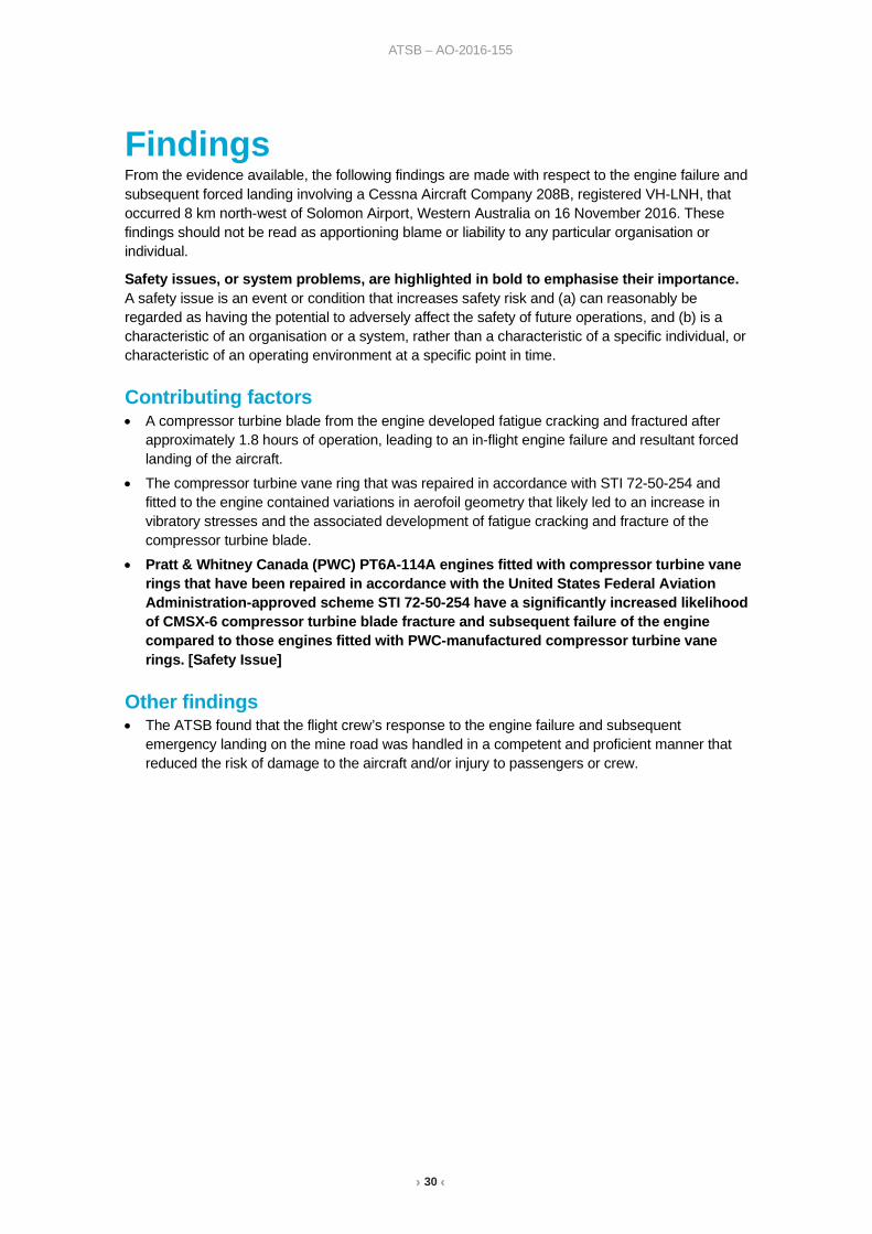
› 30 ‹
ATSB – AO-2016-155
Findings From the evidence available, the following findings are made with respect to the engine failure and subsequent forced landing involving a Cessna Aircraft Company 208B, registered VH-LNH, that occurred 8 km north-west of Solomon Airport, Western Australia on 16 November 2016. These findings should not be read as apportioning blame or liability to any particular organisation or individual.
Safety issues, or system problems, are highlighted in bold to emphasise their importance. A safety issue is an event or condition that increases safety risk and (a) can reasonably be regarded as having the potential to adversely affect the safety of future operations, and (b) is a characteristic of an organisation or a system, rather than a characteristic of a specific individual, or characteristic of an operating environment at a specific point in time.
Contributing factors • A compressor turbine blade from the engine developed fatigue cracking and fractured after
approximately 1.8 hours of operation, leading to an in-flight engine failure and resultant forced landing of the aircraft.
• The compressor turbine vane ring that was repaired in accordance with STI 72-50-254 and fitted to the engine contained variations in aerofoil geometry that likely led to an increase in vibratory stresses and the associated development of fatigue cracking and fracture of the compressor turbine blade.
• Pratt & Whitney Canada (PWC) PT6A-114A engines fitted with compressor turbine vane rings that have been repaired in accordance with the United States Federal Aviation Administration-approved scheme STI 72-50-254 have a significantly increased likelihood of CMSX-6 compressor turbine blade fracture and subsequent failure of the engine compared to those engines fitted with PWC-manufactured compressor turbine vane rings. [Safety Issue]
Other findings • The ATSB found that the flight crew’s response to the engine failure and subsequent
emergency landing on the mine road was handled in a competent and proficient manner that reduced the risk of damage to the aircraft and/or injury to passengers or crew.
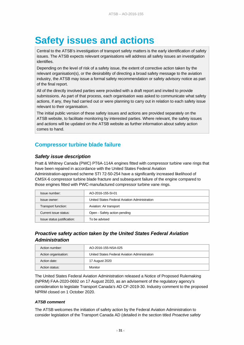
› 31 ‹
ATSB – AO-2016-155
Safety issues and actions
Compressor turbine blade failure
Safety issue description Pratt & Whitney Canada (PWC) PT6A-114A engines fitted with compressor turbine vane rings that have been repaired in accordance with the United States Federal Aviation Administration-approved scheme STI 72-50-254 have a significantly increased likelihood of CMSX-6 compressor turbine blade fracture and subsequent failure of the engine compared to those engines fitted with PWC-manufactured compressor turbine vane rings.
Proactive safety action taken by the United States Federal Aviation Administration
The United States Federal Aviation Administration released a Notice of Proposed Rulemaking (NPRM) FAA-2020-0692 on 17 August 2020, as an advisement of the regulatory agency’s consideration to legislate Transport Canada’s AD CF-2019-30. Industry comment to the proposed NPRM closed on 1 October 2020.
ATSB comment
The ATSB welcomes the initiation of safety action by the Federal Aviation Administration to consider legislation of the Transport Canada AD (detailed in the section titled Proactive safety
Central to the ATSB’s investigation of transport safety matters is the early identification of safety issues. The ATSB expects relevant organisations will address all safety issues an investigation identifies. Depending on the level of risk of a safety issue, the extent of corrective action taken by the relevant organisation(s), or the desirability of directing a broad safety message to the aviation industry, the ATSB may issue a formal safety recommendation or safety advisory notice as part of the final report. All of the directly involved parties were provided with a draft report and invited to provide submissions. As part of that process, each organisation was asked to communicate what safety actions, if any, they had carried out or were planning to carry out in relation to each safety issue relevant to their organisation. The initial public version of these safety issues and actions are provided separately on the ATSB website, to facilitate monitoring by interested parties. Where relevant, the safety issues and actions will be updated on the ATSB website as further information about safety action comes to hand.
Issue number: AO-2016-155-SI-01
Issue owner: United States Federal Aviation Administration
Transport function: Aviation: Air transport
Current issue status: Open - Safety action pending
Issue status justification: To be advised
Action number: AO-2016-155-NSA-025
Action organisation: United States Federal Aviation Administration
Action date: 17 August 2020
Action status: Monitor

› 32 ‹
ATSB – AO-2016-155
action taken by Transport Canada). However, with closure of the NPRM on 1 October 2020, at the time of writing, no decision has been made whether the AD will be adopted. As such, the safety issue will remain open, pending safety action.
The ATSB also notes that proactive safety action taken by the Civil Aviation Safety Authority (detailed in the section titled Proactive safety action taken by the Civil Aviation Safety Authority) in adopting the Transport Canada AD, reduces the likelihood of CMSX-6 single-crystal compressor turbine blade failure involving Australian-operated PT6A-114A engines to an acceptable level.
Proactive safety action taken by Transport Canada
As a result of this occurrence and other similar incidents, the national aviation administrator, Transport Canada, has taken the following proactive safety action:
Airworthiness Directive CF-2019-30 was released on 2 September 2019, linking the low-time fatigue-fracture of CMSX-6 single crystal compressor turbine blade failures and the use of compressor turbine vane rings that had been repaired in accordance with United States Federal Aviation Administration major repair specification STI 72-50-254. The AD required:
1. Within 9 months or 250 hours air time, whichever occurs first, from the effective date of this AD, determine if a CT vane, repaired in accordance with repair specification number STI 72-50-254, is installed on the affected engine and replace it with a serviceable non-STI repaired CT vane.
2. Within 9 months or 250 hours air time, whichever occurs first, from the effective date of this AD, replace and discard any CMSX-6 CT blade that has been operating in service on an engine with an above-mentioned STI repaired CT vane installation.
3. As of the effective date of this AD, it is prohibited for anyone to allow the installation of an above-mentioned STI repaired CT vane on affected engines.
On 17 December 2019, Revision 1 to AD CF-2019-30 was subsequently released by Transport Canada. The new revision contained some minor amendments to the context, however the corrective actions and compliance times remained unchanged.
ATSB comment
The ATSB is satisfied that compliance with AD CF-2019-30 will reduce the likelihood of CMSX-6 single-crystal compressor turbine blade failure within PT6A-114A engines to an acceptable level.
Proactive safety action taken by the Civil Aviation Safety Authority
Transport Canada’s AD CF-2019-30 was published on the Civil Aviation Safety Authority website as part of AD bi-weekly 17/2019. As the AD has been issued by the national aviation authority of the state of design for the affected aeronautical product (Transport Canada) it was automatically accepted under the Civil Aviation Safety Regulations (CASR) Part 39.
Australian aircraft covered by the AD are subject to the requirement of CASR 39, sub-section 003, and are therefore required to comply with the AD.
Action number: AO-2016-155-NSA-026
Action organisation: Transport Canada
Action date: 2 September 2019
Action status: Closed
Action number: AO-2016-155-NSA-027
Action organisation: Civil Aviation Safety Authority
Action date: 2 September 2019
Action status: Closed

› 33 ‹
ATSB – AO-2016-155
ATSB comment
The ATSB is satisfied that compliance with AD CF-2019-30 will reduce the likelihood of CMSX-6 single-crystal compressor turbine blade failure involving Australian-operated PT6A-114A engines to an acceptable level.
Proactive safety action taken by the Pratt & Whitney Canada
On 29 March 2017, Pratt & Whitney Canada (PWC) released Service Information Letter (SIL) PT6A-252 ‘Effect on CT Blades of CT Vanes Repaired Using Non-P&WC Approved Processes.’ The SIL advised operators of the heightened risk of high cycle fatigue fracture of single-crystal compressor turbine (CT) blades when used in conjunction with CT vanes that had been repaired using ‘non-P&WC approved processes.’
ATSB comment
The ATSB is satisfied that, with adherence to the advice contained within SIL PT6A-252, the likelihood of single-crystal compressor turbine blade failure involving PWC PT6A 114A engines will be reduced.
Proactive safety action taken by Southwest Turbine Inc.
On 16 March 2017, concerned by reports of CMSX-6 single-crystal compressor turbine blade fractures, the holder of the major repair specification for the compressor turbine vane ring, Southwest Turbine Inc., ceased conducting repairs on vane rings for fitment into Pratt and Whitney Canada (PWC) PT6A-114A engines.
Following meetings with the United States Federal Aviation Administration (FAA), Southwest Turbine Inc. completed and subsequently submitted to the US FAA a detailed engineering analysis of their compressor turbine vane ring repair, STI 72-50-254, that compared the geometry of their repair against the vane rings produced by the engine manufacturer (PWC).
ATSB comment
The ATSB notes that the action taken by Southwest Turbine Inc. to cease conducting repairs on vane rings fitted to PT6A-114A engines, reduces the risk of STI 72-50-254-related CMSX-6 compressor turbine blade fracture.
Proactive safety action taken by Aviair Pty Ltd
The operator advised that by October 2017, they had adopted the recommendations contained in Pratt & Whitney Service Information Letter, SIL PT6A-252. Their Cessna 208B fleet was reviewed,
Action number: AO-2016-155-NSA-028
Action organisation: Pratt & Whitney Canada
Action date: 29 March 2017
Action status: Closed
Action number: AO-2016-155-NSA-029
Action organisation: Southwest Turbine Inc.
Action date: 16 March 2017
Action status: Closed
Action number: AO-2016-155-NSA-030
Action organisation: Aviair Pty Ltd
Action date: October 2017
Action status: Closed

› 34 ‹
ATSB – AO-2016-155
and any STI 72-50-254 compressor turbine vane rings that had been fitted to their PT6A-114A engines, were removed and replaced with compressor turbine vanes manufactured by Pratt & Whitney Canada.
ATSB comment
The ATSB notes that adherence to the advice contained within SIL PT6A-252 reduces the likelihood of single-crystal compressor turbine blade failure involving PWC PT6A 114A engines.
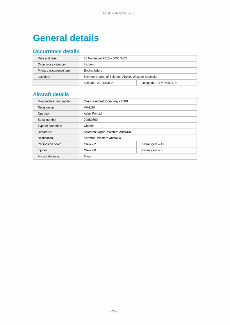
› 35 ‹
ATSB – AO-2016-155
General details Occurrence details
Date and time: 16 November 2016 – 0751 WST
Occurrence category: Incident
Primary occurrence type: Engine failure
Location: 8 km north-west of Solomon Airport, Western Australia
Latitude: 22° 1.575' S Longitude: 117° 48.577' E
Aircraft details Manufacturer and model: Cessna Aircraft Company - 208B
Registration: VH-LNH
Operator: Aviair Pty Ltd
Serial number: 208B0590
Type of operation: Charter
Departure: Solomon Airport, Western Australia
Destination: Karratha, Western Australia
Persons on board: Crew – 2 Passengers – 11
Injuries: Crew – 0 Passengers – 0
Aircraft damage: Minor

› 36 ‹
ATSB – AO-2016-155
Sources and submissions Sources of information The sources of information during the investigation included:
• Aviair Pty Ltd • The pilots from the occurrence aircraft • Pratt & Whitney Canada • Cessna - Textron Aviation • United States Federal Aviation Administration • Transport Canada • Southwest Turbine Inc.
Submissions Under Part 4, Division 2 (Investigation Reports), Section 26 of the Transport Safety Investigation Act 2003 (the Act), the ATSB may provide a draft report, on a confidential basis, to any person whom the ATSB considers appropriate. Section 26 (1) (a) of the Act allows a person receiving a draft report to make submissions to the ATSB about the draft report.
A draft of this report was provided to the operating flight crew of VH-LNH, Aviair Pty Ltd, Transport Canada, Transport Safety Board of Canada, Pratt & Whitney Canada, United States Federal Aviation Administration, Southwest Turbine Inc., United States National Transportation Safety Board, and the Civil Aviation Safety Authority.
Submissions were received from:
• Aviair Pty Ltd
• the Civil Aviation Safety Authority
• Pratt and Whitney Canada
• Southwest Turbine Inc.
• the United States National Transportation Safety Board
• the United States Federal Aviation Administration.
The submissions were reviewed and where considered appropriate, the text of the report was amended accordingly.

› 37 ‹
ATSB – AO-2016-155
Appendix A: Compressor turbine vane ring measurements Figure A1: The measured vane chord length and trailing edge thickness measurements of the STI-repaired CT vane ring from the occurrence engine (Aviair Cessna 208, VH-LNH) compared to the Pratt & Whitney Canada design tolerance.
Image source: Pratt & Whitney Canada

› 38 ‹
ATSB – AO-2016-155
Figure A2: The respective vane stagger angles of the STI-repaired compressor turbine vane ring from the occurrence engine (Aviair Cessna 208, VH-LNH) compared to the Pratt & Whitney Canada design tolerance.
Image source: Pratt & Whitney Canada
Figure A3: The vane stagger angles of three STI-repaired compressor turbine vane rings fitted to three PT6A-114A engines that had sustained compressor turbine blade fracture, compared a CT vane ring with a Pratt & Whitney Canada CT vane ring that had also sustained a CT blade failure.
Image source: Pratt & Whitney Canada

› 39 ‹
ATSB – AO-2016-155
Australian Transport Safety Bureau The ATSB is an independent Commonwealth Government statutory agency. The ATSB is governed by a Commission and is entirely separate from transport regulators, policy makers and service providers. The ATSB’s function is to improve safety and public confidence in the aviation, marine and rail modes of transport through excellence in: independent investigation of transport accidents and other safety occurrences; safety data recording, analysis and research; fostering safety awareness, knowledge and action.
The ATSB is responsible for investigating accidents and other transport safety matters involving civil aviation, marine and rail operations in Australia that fall within the ATSB’s jurisdiction, as well as participating in overseas investigations involving Australian registered aircraft and ships. A primary concern is the safety of commercial transport, with particular regard to operations involving the travelling public.
The ATSB performs its functions in accordance with the provisions of the Transport Safety Investigation Act 2003 and Regulations and, where applicable, relevant international agreements.
Purpose of safety investigations The object of a safety investigation is to identify and reduce safety-related risk. ATSB investigations determine and communicate the factors related to the transport safety matter being investigated.
It is not a function of the ATSB to apportion blame or determine liability. At the same time, an investigation report must include factual material of sufficient weight to support the analysis and findings. At all times the ATSB endeavours to balance the use of material that could imply adverse comment with the need to properly explain what happened, and why, in a fair and unbiased manner.
Developing safety action Central to the ATSB’s investigation of transport safety matters is the early identification of safety issues in the transport environment. The ATSB prefers to encourage the relevant organisation(s) to initiate proactive safety action that addresses safety issues. Nevertheless, the ATSB may use its power to make a formal safety recommendation either during or at the end of an investigation, depending on the level of risk associated with a safety issue and the extent of corrective action undertaken by the relevant organisation.
When safety recommendations are issued, they focus on clearly describing the safety issue of concern, rather than providing instructions or opinions on a preferred method of corrective action. As with equivalent overseas organisations, the ATSB has no power to enforce the implementation of its recommendations. It is a matter for the body to which an ATSB recommendation is directed to assess the costs and benefits of any particular means of addressing a safety issue.
When the ATSB issues a safety recommendation to a person, organisation or agency, they must provide a written response within 90 days. That response must indicate whether they accept the recommendation, any reasons for not accepting part or all of the recommendation, and details of any proposed safety action to give effect to the recommendation.
The ATSB can also issue safety advisory notices suggesting that an organisation or an industry sector consider a safety issue and take action where it believes it appropriate. There is no requirement for a formal response to an advisory notice, although the ATSB will publish any response it receives.

› 40 ‹
ATSB – AO-2016-155
Terminology used in this report Occurrence: accident or incident.
Safety factor: an event or condition that increases safety risk. In other words, it is something that, if it occurred in the future, would increase the likelihood of an occurrence, and/or the severity of the adverse consequences associated with an occurrence. Safety factors include the occurrence events (e.g. engine failure, signal passed at danger, grounding), individual actions (e.g. errors and violations), local conditions, current risk controls and organisational influences.
Contributing factor: a factor that, had it not occurred or existed at the time of an occurrence, then either:
(a) the occurrence would probably not have occurred; or
(b) the adverse consequences associated with the occurrence would probably not have occurred or have been as serious, or
(c) another contributing factor would probably not have occurred or existed.
Other factors that increased risk: a safety factor identified during an occurrence investigation, which did not meet the definition of contributing factor but was still considered to be important to communicate in an investigation report in the interest of improved transport safety.
Other findings: any finding, other than that associated with safety factors, considered important to include in an investigation report. Such findings may resolve ambiguity or controversy, describe possible scenarios or safety factors when firm safety factor findings were not able to be made, or note events or conditions which ‘saved the day’ or played an important role in reducing the risk associated with an occurrence.