ENGINE CONTROL SYSTEM EC - Club Nissan · Engine Fuel & Emission Control System NEF390 ECM (ECCS-D...
148
ENGINE CONTROL SYSTEM SECTION EC CONTENTS CD20T PRECAUTIONS AND PREPARATION.......................... 3 Special Service Tools ................................................ 3 Engine Fuel & Emission Control System .................. 5 Supplemental Restraint System (SRS) ″AIR BAG″ and ″SEAT BELT PRE-TENSIONER″ ............. 6 Precautions for On Board Diagnostic (OBD) System of Engine ...................................................... 6 Precautions ................................................................ 7 ENGINE AND EMISSION CONTROL OVERALL SYSTEM......................................................................... 9 Engine Control Module Component Parts Location ..................................................................... 9 Circuit Diagram ......................................................... 11 System Diagram ...................................................... 12 Vacuum Hose Drawing ............................................ 13 System Chart ........................................................... 14 ENGINE AND EMISSION BASIC CONTROL SYSTEM DESCRIPTION ............................................. 15 Glow Control System............................................... 15 Fuel Injection System .............................................. 15 Fuel Injection Timing System .................................. 18 Air Conditioning Cut Control .................................... 20 Cooling Fan Control................................................. 20 CRANKCASE VENTILATION SYSTEM...................... 21 Description ............................................................... 21 Blow-by Control Valve ............................................. 21 Ventilation Hose ....................................................... 21 INJECTION NOZZLE................................................... 22 Removal and Installation ......................................... 22 Test and Adjustment ................................................ 22 ELECTRONIC FUEL INJECTION PUMP.................... 24 Removal ................................................................... 24 Installation ................................................................ 25 Disassembly and Assembly ..................................... 26 ON BOARD DIAGNOSTIC SYSTEM DESCRIPTION ............................................................. 27 CONSULT-II ............................................................. 27 TROUBLE DIAGNOSIS - INTRODUCTION................ 33 Introduction .............................................................. 33 Diagnostic Worksheet .............................................. 34 TROUBLE DIAGNOSIS - WORK FLOW .................... 35 Work Flow ................................................................ 35 Description for Work Flow ....................................... 36 TROUBLE DIAGNOSIS - BASIC INSPECTION......... 37 Basic Inspection....................................................... 37 TROUBLE DIAGNOSIS - GENERAL DESCRIPTION ............................................................. 39 Diagnostic Trouble Chart ......................................... 39 Symptom Matrix Chart ............................................. 47 CONSULT-II Reference Value in Data Monitor Mode ........................................................................ 50 Major Sensor Reference Graph in Data Monitor Mode ........................................................................ 51 ECM Terminals and Reference Value ..................... 52 TROUBLE DIAGNOSIS FOR POWER SUPPLY ........ 59 Main Power Supply and Ground Circuit .................. 59 TROUBLE DIAGNOSIS 1............................................ 62 Mass Air Flow Sensor (MAFS) ................................ 62 TROUBLE DIAGNOSIS 2............................................ 66 Engine Coolant Temperature (ECT) Sensor ........... 66 TROUBLE DIAGNOSIS 3............................................ 70 Vehicle Speed Sensor (VSS) .................................. 70 TROUBLE DIAGNOSIS 4............................................ 74 Control Sleeve Position Sensor (CSPS) ................. 74 TROUBLE DIAGNOSIS 5............................................ 78 Electric Governor ..................................................... 78 TROUBLE DIAGNOSIS 6............................................ 82 EC
Transcript of ENGINE CONTROL SYSTEM EC - Club Nissan · Engine Fuel & Emission Control System NEF390 ECM (ECCS-D...

ENGINE CONTROL SYSTEM
SECTIONEC
CONTENTS
CD20T
PRECAUTIONS AND PREPARATION .......................... 3Special Service Tools ................................................ 3Engine Fuel & Emission Control System .................. 5Supplemental Restraint System (SRS) ″AIRBAG″ and ″SEAT BELT PRE-TENSIONER″............. 6Precautions for On Board Diagnostic (OBD)System of Engine ...................................................... 6Precautions ................................................................ 7
ENGINE AND EMISSION CONTROL OVERALLSYSTEM......................................................................... 9
Engine Control Module Component PartsLocation ..................................................................... 9Circuit Diagram.........................................................11System Diagram ...................................................... 12Vacuum Hose Drawing ............................................ 13System Chart ........................................................... 14
ENGINE AND EMISSION BASIC CONTROLSYSTEM DESCRIPTION ............................................. 15
Glow Control System............................................... 15Fuel Injection System .............................................. 15Fuel Injection Timing System .................................. 18Air Conditioning Cut Control.................................... 20Cooling Fan Control................................................. 20
CRANKCASE VENTILATION SYSTEM ...................... 21Description ............................................................... 21Blow-by Control Valve ............................................. 21Ventilation Hose....................................................... 21
INJECTION NOZZLE ................................................... 22Removal and Installation ......................................... 22Test and Adjustment ................................................ 22
ELECTRONIC FUEL INJECTION PUMP .................... 24Removal................................................................... 24Installation................................................................ 25
Disassembly and Assembly..................................... 26ON BOARD DIAGNOSTIC SYSTEMDESCRIPTION ............................................................. 27
CONSULT-II ............................................................. 27TROUBLE DIAGNOSIS - INTRODUCTION ................ 33
Introduction .............................................................. 33Diagnostic Worksheet.............................................. 34
TROUBLE DIAGNOSIS - WORK FLOW .................... 35Work Flow................................................................ 35Description for Work Flow ....................................... 36
TROUBLE DIAGNOSIS - BASIC INSPECTION ......... 37Basic Inspection....................................................... 37
TROUBLE DIAGNOSIS - GENERALDESCRIPTION ............................................................. 39
Diagnostic Trouble Chart ......................................... 39Symptom Matrix Chart............................................. 47CONSULT-II Reference Value in Data MonitorMode........................................................................ 50Major Sensor Reference Graph in Data MonitorMode........................................................................ 51ECM Terminals and Reference Value ..................... 52
TROUBLE DIAGNOSIS FOR POWER SUPPLY ........ 59Main Power Supply and Ground Circuit.................. 59
TROUBLE DIAGNOSIS 1 ............................................ 62Mass Air Flow Sensor (MAFS) ................................ 62
TROUBLE DIAGNOSIS 2 ............................................ 66Engine Coolant Temperature (ECT) Sensor ........... 66
TROUBLE DIAGNOSIS 3 ............................................ 70Vehicle Speed Sensor (VSS) .................................. 70
TROUBLE DIAGNOSIS 4 ............................................ 74Control Sleeve Position Sensor (CSPS) ................. 74
TROUBLE DIAGNOSIS 5 ............................................ 78Electric Governor ..................................................... 78
TROUBLE DIAGNOSIS 6 ............................................ 82
EC

Injection Timing Control Valve ................................. 82TROUBLE DIAGNOSIS 7 ............................................ 86
Engine Control Module (ECM) ................................ 86TROUBLE DIAGNOSIS 8 ............................................ 87
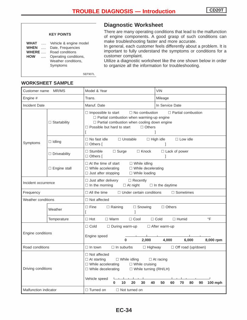
Cooling Fan (Overheat) ........................................... 87TROUBLE DIAGNOSIS 9 ............................................ 97
Needle Lift Sensor (NLS) ........................................ 97TROUBLE DIAGNOSIS 10 ........................................ 100
Fuel Cut Solenoid Valve ........................................ 100TROUBLE DIAGNOSIS 11 ........................................ 104
Fuel Temperature Sensor (FTS)............................ 104TROUBLE DIAGNOSIS 12 ........................................ 108
Accelerator Position Sensor & Switch................... 108TROUBLE DIAGNOSIS 13 .........................................114
Crankshaft Position Sensor (TDC) .........................114TROUBLE DIAGNOSES 14 .......................................118
Glow Control System..............................................118
TROUBLE DIAGNOSES 15 ...................................... 126Air Conditioner Cut Control ................................... 126
TROUBLE DIAGNOSES 16 ...................................... 129EGRC-Solenoid Valve ........................................... 129
TROUBLE DIAGNOSES 17 ...................................... 136Brake Switch.......................................................... 136
TROUBLE DIAGNOSES 18 ...................................... 140ECM Relay............................................................. 140
TROUBLE DIAGNOSES 19 ...................................... 141MI & Data Link Connectors ................................... 141
TROUBLE DIAGNOSES 20 ...................................... 145Start Signal ............................................................ 145
SERVICE DATA AND SPECIFICATIONS (SDS) ...... 147General Specifications........................................... 147Injection Nozzle ..................................................... 147Inspection and Adjustment .................................... 147
When you read wiring diagrams: Read GI section, “HOW TO READ WIRING DIAGRAMS”. See EL section, “POWER SUPPLY ROUTING” for power distribution circuit. See EL section for NATS information and wiring diagram.When you perform trouble diagnoses, read GI section, “HOW TO FOLLOW FLOW CHARTIN TROUBLE DIAGNOSES” and “HOW TO PERFORM EFFICIENT DIAGNOSIS FOR ANELECTRICAL INCIDENT”.For clarification of system component abbreviations and terminology read GI section“SAE J1930 TERMINOLOGY LIST”.
EC-2

Special Service Tools
Tool numberTool name
Description
KV11289004Nozzle cleaning kit
p1 KV11290012Box
p2 KV11290110Brush
p3 KV11290122Nozzle oil sumpscraper
p4 KV11290140Nozzle needle tipcleaner
p5 KV11290150Nozzle seat scraper
p6 KV11290210Nozzle holder
p7 KV11290220Nozzle hole clean-ing needle
NT296
KV109E0010Break-out box
NT825
KV109E0050Y-cable adapter
NT826
KV11292010Nozzle centering device
NT293
KV11100300No. 2-4 injection nozzleholder socket
NT563
PRECAUTIONS AND PREPARATION CD20T
EC-3

Tool numberTool name
Description
KV119E0030No. 1 injection nozzleholder socket
NT648
PRECAUTIONS AND PREPARATION CD20T
Special Service Tools (Cont’d)
EC-4

Engine Fuel & Emission Control System
NEF390
ECM (ECCS-D control module) Do not disassemble ECM. If a battery terminal is disconnected, the memory
will return to the ECM value.The ECM will now start to self-control at its initialvalue. Engine operation can vary slightly whenthe terminal is disconnected. However, this is notan indication of a problem. Do not replace partsbecause of a slight variation.
When ECM is removed for inspection, make sureto ground the ECM mainframe.
WIRELESS EQUIPMENT When installing C.B. ham radio or a mobile
phone, be sure to observe the following as itmay adversely affect electronic control sys-tems depending on its installation location.
1) Keep the antenna as far as possible awayfrom the ECM.
2) Keep the antenna feeder line more than20 cm (7.9 in) away from the harness of elec-tronic controls.Do not let them run parallel for a long dis-tance.
3) Adjust the antenna and feeder line so that thestanding-wave ratio can be kept small.
4) Be sure to ground the radio to vehicle body.
ECM HARNESS HANDLING Connect ECM harness connectors securely.
A poor connection can cause an extremelyhigh (surge) voltage to develop in coil andcondenser, thus resulting in damage to ICs.
Keep ECM harness at least 10 cm (3.9 in)away from adjacent harnesses, to prevent anECM system malfunction due to receivingexternal noise, degraded operation of ICs,etc.
Keep ECM parts and harnesses dry. Before removing parts, turn off ignition
switch and then disconnect battery groundcable.
WHEN STARTING Do not depress accelerator pedal when
starting. Immediately after starting, do not rev up
engine unnecessarily. Do not rev up engine just prior to shut-
down.
ECM PARTS HANDLING Handle mass air flow sensor carefully to avoid
damage. Do not disassemble mass air flow sensor. Do not clean mass air flow sensor with any type
of detergent. Do not disassemble No. 1 injection nozzle (built-
in needle lift sensor). Even a slight leak in the air intake system can
cause serious problems. Do not shock or jar the camshaft position sensor
(TDC).
ELECTRONIC FUEL INJECTOR PUMP Do not disconnect pump harness connectors
with engine running. Do not disassemble or adjust electronic fuel
injection pump, except for the followingparts.Camshaft position sensor (pump)Injection timing control valveFuel cut solenoid valve
BATTERY Always use a 12 volt battery as power
source. Do not attempt to disconnect battery cables
while engine is running.
ECM mainframe
PRECAUTIONS AND PREPARATION CD20T
EC-5

Supplemental Restraint System (SRS) “AIRBAG” and “SEAT BELT PRE-TENSIONER”
NCEC0002
The Supplemental Restraint System “AIR BAG” and “SEAT BELT PRE-TENSIONER”, used along with a seatbelt, help to reduce the risk or severity of injury to the driver and front passenger in a frontal collision. TheSupplemental Restraint System consists of air bag modules (located in the center of the steering wheel andon the instrument panel on the passenger side), seat belt pre-tensioners, a diagnosis sensor unit, warninglamp, wiring harness and spiral cable.In addition to the supplemental air bag modules for a frontal collision, the supplemental side air bag usedalong with the seat belt helps to reduce the risk or severity of injury to the driver and front passenger in aside collision. The supplemental side air bag consists of air bag modules (located in the outer side of frontseats), satellite sensor, diagnosis sensor unit (one of components of supplemental air bags for a frontalcollision), wiring harness, warning lamp (one of components of supplemental air bags for a frontal collision).Information necessary to service the system safely is included in the RS section of this Service Manual.WARNING: To avoid rendering the SRS inoperative, which could increase the risk of personal injury or death
in the event of a collision which would result in air bag inflation, all maintenance must be per-formed by an authorized NISSAN dealer.
Improper maintenance, including incorrect removal and installation of the SRS, can lead to per-sonal injury caused by unintentional activation of the system.
Do not use electrical test equipment on any circuit related to the SRS unless instructed to in thisService Manual. SRS wiring harnesses (except “SEAT BELT PRE-TENSIONER” connector) can beidentified with yellow harness connector (and with yellow harness protector or yellow insulationtape before the harness connectors).
Precautions for On Board Diagnostic (OBD)System of Engine
NCEC0003
The ECM has an on board diagnostic system. It will light up the malfunction indicator (MI) to warn the driverof a malfunction causing emission deterioration.CAUTION: Be sure to turn the ignition switch “OFF” and disconnect the negative battery terminal before any
repair or inspection work. The open/short circuit of related switches, sensors, solenoid valves,etc. will cause the MI to light up.
Be sure to connect and lock the connectors securely after work. A loose (unlocked) connectorwill cause the MI to light up due to the open circuit. (Be sure the connector is free from water,grease, dirt, bent terminals, etc.)
Certain systems and components, especially those related to OBD, may use a new style slide-locking type harness connector.For description and how to disconnect, refer to EL section, “Description”, “HARNESS CONNEC-TOR”.
Be sure to route and secure the harnesses properly after work. The interference of the harnesswith a bracket, etc. may cause the MI to light up due to the short circuit.
Be sure to connect rubber tubes properly after work. A misconnected or disconnected rubbertube may cause the MI to light up due to the malfunction of the EGR system or fuel injectionsystem, etc.
Be sure to erase the unnecessary malfunction information (repairs completed) from the ECMbefore returning the vehicle to the customer.
PRECAUTIONS AND PREPARATION CD20T
EC-6

Precautions Before connecting or disconnecting the ECM harness
connector, turn ignition switch OFF and disconnectnegative battery terminal. Failure to do so may damagethe ECM because battery voltage is applied to ECM evenif ignition switch is turned off.
When connecting ECM harness connectors, push inboth sides of the connector until you hear a click.Maneuver the lever until you hear the three connectorson the inside click. Refer to the figure at left.
Before replacing ECM, perform Terminals and ReferenceValue inspection and make sure ECM functions properly.Refer to EC-CD-52.
If MI illuminates or blinks irregularly during enginerunning, water may have accumulated in fuel filter. Drainwater from fuel filter. If this does not correct the problem,perform specified trouble diagnostic procedures.
After performing each TROUBLE DIAGNOSIS, perform“OVERALL FUNCTION CHECK” or “DTC (DiagnosticTrouble Code) CONFIRMATION PROCEDURE”.The DTC should not be displayed in the “DTC CONFIR-MATION PROCEDURE” if the repair is completed. The“OVERALL FUNCTION CHECK” should be a good resultif the repair is completed.
SEF289H
SEF881Y
MEF040D
SAT652J
PRECAUTIONS AND PREPARATION CD20T
EC-7

When measuring ECM signals with a circuit tester, neverallow the two tester probes to contact.Accidental contact of probes will cause a short circuitand damage the ECM power transistor.
SEF348N
PRECAUTIONS AND PREPARATION CD20T
Precautions (Cont’d)
EC-8

Engine Control Module Component PartsLocation
YEC133A
ENGINE AND EMISSION CONTROL OVERALL SYSTEM CD20T
EC-9

YEC134A
ENGINE AND EMISSION CONTROL OVERALL SYSTEM CD20T
Engine Control Module Component PartsLocation (Cont’d)
EC-10

Circuit Diagram
YEC099A
ENGINE AND EMISSION CONTROL OVERALL SYSTEM CD20T
EC-11

System Diagram
YEC125A
ENGINE AND EMISSION CONTROL OVERALL SYSTEM CD20T
EC-12
Vacuum Hose Drawing
p1 EGRC-solenoid valves A and B to EGR valve
p2 EGRC-solenoid valves A and B to air duct
p3 EGRC-solenoid valve A to vacuum pump
Refer to “System Diagram” on previous page for vacuum control system.
YEC131A
ENGINE AND EMISSION CONTROL OVERALL SYSTEM CD20T
EC-13

System Chart
Crankshaft position sensor(TDC)
E
ECM
Control sleeve position sensor E
Fuel temperature sensor E
Mass air flow sensor E
Engine coolant temperaturesensor
E
Needle lift sensor E
Accelerator position sensor E
Accelerator position switch E
Air conditioner switch E
Ignition switch (ON & ST POS.) E
Battery voltage E
Vehicle speed sensor or ABSactuator and electric unit (con-trol unit)
E
Brake switch E
Atmospheric pressure sensor E
E Fuel injection control E Electric governor
E Fuel injection timing control E Injection timing controlvalve
E Fuel cut control E Fuel cut solenoid valve
E Glow control system E Glow relay & glow lamp
E On board diagnostic system E Malfunction indicator(On the instrument panel)
E EGR valve control E EGRC-solenoid valve A & B
E Cooling fan control E Cooling fan relays
E Air conditioning cut control E Air conditioner relay
E Cooling fan motor control E Cooling fan relay
ENGINE AND EMISSION CONTROL OVERALL SYSTEM CD20T
EC-14

Glow Control SystemSYSTEM DESCRIPTION
Crankshaft position sensor (TDC) EEngine speed
ECME Glow relay E Glow plugs
Engine coolant temperature sensor EEngine coolant temperature
E Glow lamp
When coolant temperature is lower than 75°C (167°F): Ignition switch ON
After the ignition switch has been turned to ON, the glowrelay turns ON for a period of time depending on the enginecoolant temperature, allowing current to flow through theglow plugs.
StartingAfter starting the engine, current will flow through the glowplugs for 300 seconds, or until the coolant temperatureexceeds 50°C (122°F).
Fuel Injection SystemSYSTEM DESCRIPTIONThree types of fuel injection control are provided to accommodate the engine operating conditions; normalcontrol, idle control and start control. The ECM determines the appropriate fuel injection control. Under eachcontrol, the amount of fuel injected is compensated to improve engine performance. The ECM performs dutycycle control on the electric governor (built into the fuel injection pump) according to sensor signals to com-pensate the amount of fuel injected to the preset value.
START CONTROL
Input/output signal line
Engine coolant temperature sensor EEngine coolant temperature
ECM EElectricgovernor
Crankshaft position sensor (TDC) EEngine speed
Control sleeve position sensor EControl sleeve position
When starting, the ECM adapts the fuel injection system for thestart control. The amount of fuel injected at engine starting is apreset program value in the ECM. The program is determined bythe engine speed and engine coolant temperature.For better startability under cool engine conditions, the lower thecoolant temperature becomes, the greater the amount of fuelinjected. The ECM ends the start control when the engine speedreaches a coolant temperature dependent value.
SEF648S
Coolant temperaturegetting lower
Engine rpm
Fue
linj
ectio
nvo
lum
e
ENGINE AND EMISSION BASIC CONTROL SYSTEM DESCRIPTION CD20T
EC-15

IDLE CONTROL
Input/output signal line
Engine coolant temperature sensor EEngine coolant temperature
ECME
Electricgovernor
Crankshaft position sensor (TDC) EEngine speed
Air conditioner switch EAir conditioner operation
Control sleeve position sensor EControl sleeve position
Accelerator position switch EIdle position
Vehicle speed sensor or ABS actuatorand electric unit (control unit)
EVehicle speed
When the ECM determines that the engine speed is at idle, the fuel injection system is adapted for the idlecontrol. The ECM regulates the amount of fuel injected corresponding to changes in load applied to theengine to keep engine speed constant. During the first 270s after a cold start, the ECM also provides thesystem with a fast idle control in response to the engine coolant temperature.
NORMAL CONTROL
Input/output signal line
Crankshaft position sensor (TDC) EEngine speed
ECM EElectricgovernor
Control sleeve position sensor EControl sleeve position
Accelerator position sensor EAccelerator position
Vehicle speed sensor or ABS actuatorand electric unit (control unit)
EVehicle speed
The amount of fuel injected under normal driving conditions isdetermined according to sensor signals. The crankshaft positionsensor (TDC) detects engine speed and the accelerator positionsensor detects accelerator position. These sensors send signalsto the ECM.The fuel injection data, predetermined by correlation betweenvarious engine speeds and accelerator positions, are stored inthe ECM memory, forming a map. The ECM determines theoptimal amount of fuel to be injected using the sensor signals incomparison with the map.
SEF649S
Fue
linj
ectio
nvo
lum
e
Acceleratoropening larger
Engine rpm
ENGINE AND EMISSION BASIC CONTROL SYSTEM DESCRIPTION CD20T
Fuel Injection System (Cont’d)
EC-16

FUEL TEMPERATURE COMPENSATION
Input/output signal line
Fuel temperature sensor EFuel temperature
ECME
ElectricgovernorCrankshaft position sensor (TDC) E
Engine speed
Control sleeve position sensor EControl sleeve position
The amount of fuel leaking at or around high-pressure parts inside the fuel injection pump varies with fueltemperature and engine speed. This will result in a difference between the target amount of fuel injected andthe actual amount. The ECM compensates for the actual amount depending on the signal from the fueltemperature sensor, the control sleeve position sensor and the crankshaft position sensor.
DECELERATION CONTROL
Input/output signal line
Accelerator sensor EAccelerator position
ECM EElectricgovernor
Camshaft position sensor (PUMP) EEngine speed
The ECM cuts power supply delivery to the electric governor during deceleration for better fuel efficiency.The ECM determines the time of deceleration according to signals from the accelerator sensor and cam-shaft position sensor (PUMP).
ENGINE AND EMISSION BASIC CONTROL SYSTEM DESCRIPTION CD20T
Fuel Injection System (Cont’d)
EC-17

Fuel Injection Timing SystemSYSTEM DESCRIPTIONThe fuel injection timing system determines the optimal fuel injection timing, based on engine speed, injec-tion quantity, engine coolant temperature and atmospheric pressure. The timing is formed by a basic value(Basic Control) and two correction values. By performing a duty cycle signal on the timing control valve, theECM allows the valve to provide optimal injection timing. The ECM also performs feedback control on thetiming control valve using the signal from the needle lift sensor which detects the actual fuel injection tim-ing.
BASIC CONTROL
Input/output signal line
Crankshaft position sensor (TDC) EEngine speed
ECM E
Injectiontiming con-trol valve
Needle lift sensor EInjection timing
Control sleeve position sensor EControl sleeve position
The optimal fuel injection timing data, predetermined in propor-tion to engine speeds and amount of fuel injected, are stored inthe ECM memory. The ECM uses the data to control the fuelinjection timing.
HIGH ALTITUDE COMPENSATION
Crankshaft position sensor EEngine speed
ECME
Injectiontimingcontrolvalve
Control sleeve position sensor EControl sleeve position
Atmospheric pressure sensor EAtmospheric pressure
Needle lift sensor EInjection timing
Fuel temperature sensor EFuel temperature
For better drivability in high altitude areas, the fuel injection tim-ing is advanced and the fuel quantity is reduced according to theatmospheric pressure.
SEF650S
Fue
linj
ectio
ntim
ing
BTDC(degree) Fuel injection
volume
Large
Small
Engine rpm
NEF771
Fue
linj
ectio
ntim
ing
com
pens
atio
n
Normal
High altitude
Engine rpm
ENGINE AND EMISSION BASIC CONTROL SYSTEM DESCRIPTION CD20T
EC-18

ENGINE COOLANT TEMPERATURE COMPENSATION (During driving)
Input/output signal line
Crankshaft position sensor (TDC) EEngine speed
ECME
Injectiontiming con-trol valve
Engine coolant temperature sensor EEngine coolant temperature
Needle lift sensor EInjection timing
Control sleeve position sensor EControl sleeve position
For better exhaust efficiency under cool engine conditions, thefuel injection timing is controlled within a compensation rangedepending on the engine speed, engine coolant temperature andamount of fuel injected.
ENGINE COOLANT TEMPERATURE COMPENSATION (When starting)
Input/output signal line
Crankshaft position sensor (TDC) EEngine speed
ECME
Injectiontiming con-trol valve
Engine coolant temperature sensor EEngine coolant temperature
Needle lift sensor EIgnition timing
For better startability under cool engine conditions, the fuel injec-tion timing is compensated according to the engine coolant tem-perature.
SEF652S
Fue
linj
ectio
ntim
ing
com
pens
atio
n Engine coolanttemperature
Low
High
Engine rpm
SEF651S
Fue
linj
ectio
ntim
ing
com
pens
atio
n
Engine coolanttemperature
High
Engine rpm
Low
ENGINE AND EMISSION BASIC CONTROL SYSTEM DESCRIPTION CD20T
Fuel Injection Timing System (Cont’d)
EC-19

Air Conditioning Cut ControlINPUT/OUTPUT SIGNAL LINE
Air conditioner switch or ABS actuatorand electric unit (control unit)
EAir conditioner “ON” signal
ECM EAirconditionerrelay
Accelerator position sensor EAccelerator valve opening angle
Vehicle speed sensor EVehicle speed
Engine coolant temperature sensor EEngine coolant temperature
SYSTEM DESCRIPTIONThis system improves acceleration when the air conditioner is used.When the accelerator pedal is fully depressed, the air conditioner is turned off for a few seconds.When engine coolant temperature becomes excessively high, the air conditioner is turned off. This contin-ues until the coolant temperature returns to normal.
Cooling Fan ControlINPUT/OUTPUT SIGNAL LINE
Vehicle speed sensor or ABS actuatorand electric unit (control unit)
EVehicle speed
ECM E Cooling fan relay(s)Engine coolant temperature sensor
EEngine coolant temperature
Air conditioner switchE
Air conditioner “ON” signal
The ECM controls the cooling fan corresponding to the vehicle speed, engine coolant temperature, and airconditioner ON signal. The control system has 3-step control [OFF/LOW/HIGH].
Operation
NEF772
Eng
ine
cool
ant
tem
pera
ture
°C(°
F)
Air conditioner is OFF
.
102 (216)
.
96 (205)
.20
(12)
.80
(50)Vehicle speed km/h (mph)
Cooling fans do not operate Cooling fans operate at high speed
Eng
ine
cool
ant
tem
pera
ture
°C(°
F)
Vehicle speed km/h (mph)
.20
(12)
.80
(50)
.
102 (216)
.
96 (205)
Air conditioner is ON
Cooling fans operate at low speed
ENGINE AND EMISSION BASIC CONTROL SYSTEM DESCRIPTION CD20T
EC-20

Description In this system blow-by gas is sucked into the air inlet pipe
through the control valve after oil separation by the oil sepa-rator in the rocker cover.
Blow-by Control Valve Check control valve for clogging and abnormalities.
Ventilation Hose1. Check hoses and hose connections for leaks.2. Disconnect all hoses and clean with compressed air.
If any hose cannot be freed of obstructions, replace.
SEF851S
Blow-by controlvalve
FRESH AIR
BLOW BYGAS
Baffle plate
SEC586B
Blow-by control valve
Rocker cover
Intakemanifold
SEC692
CRANKCASE VENTILATION SYSTEM CD20T
EC-21

CAUTION: Do not disassemble injection nozzle assembly. Entrust
disassembly or adjustment to BOSCH service shop. Plug flare nut with a cap or rag so that no dust enters the
nozzle.
Removal and Installation1. Remove fuel injection tube and spill tube.2. Remove injection nozzle assembly.Also remove gasket from nozzle end.3. Install injection nozzle in the reverse order of removal.
Injection nozzle to engine:: 59 - 69 N·m (6.0 - 7.0 kg-m, 43 - 51 ft-lb)
Injection nozzle to tube:: 22 - 25 N·m (2.2 - 2.5 kg-m, 16 - 18 ft-lb)
Spill tube:: 39 - 49 N·m (4.0 - 5.0 kg-m, 29 - 36 ft-lb)
a. Always clean the nozzle holes.b. Always use new injection nozzle gasket.c. Note that small washer should be installed in specified
direction.d. Bleed air from fuel system.
Test and AdjustmentWARNING:When using nozzle tester, be careful not to allow diesel fuelsprayed from nozzle to contact your hands or body, andmake sure your eyes are properly protected with goggles.
INJECTION PRESSURE TEST1. Install nozzle to injection nozzle tester and bleed air from
flare nut.
NEF396
Nozzle side
Combustionchamber side
NEF774
No. 1 injection nozzle
EF791A
INJECTION NOZZLE CD20T
EC-22

2. Pump the tester handle slowly (one time per second) andwatch the pressure gauge.
3. Read the pressure gauge when the injection pressure juststarts dropping.
Initial injection pressure:Used
14,423 - 15,651 kPa(144.2 - 156.5 bar,148 - 159 kg/cm 2, 2,091 - 2,269 psi)
New15,000 - 16,000 kPa(150.0 - 160.0 bar,153 - 163 kg/cm 2, 2,175 - 2,320 psi)
Always check initial injection pressure using a new nozzle.If the pressure is not correct, replace nozzle assembly.
LEAKAGE TEST1. Maintain the pressure at about 981 to 1,961 kPa (9.8 to 19.6
bar, 10 to 20 kg/cm2, 142 to 284 psi) below initial injectionpressure.
2. Check that there is no dripping from the nozzle tip or aroundthe body.
3. If there is leakage, replace nozzle.
SPRAY PATTERN TEST1. Check spray pattern by pumping tester handle one full stroke
per second.a. If main spray angle is within 30 degrees as shown, injec-
tion nozzle is good.b. It is still normal even if a thin stream of spray deviates
from the main spray (pattern B).2. Test again and if spray pattern is not corrected, replace
nozzle.
SEF672A
SEF674A
Good Faulty
SEF079S
INJECTION NOZZLE CD20T
Test and Adjustment (Cont’d)
EC-23

p1 Rear back cover
p2 Injection pump sprocket
p3 Injection pump bracket
p4 Water connector
p5 Bracket
p6 Bracket
p7 Electronic fuel injection pump
p8 Key
Removal1. Remove battery.
Disconnect electronic injection pump harness connectors.
2. Set No. 1 piston at TDC on its compression stroke.TDC: Crankshaft pulley notch without painted mark
3. Remove fuel hoses (supply, return and spill) and injectiontubes.
4. Remove air duct and injection pump timing belt cover.5. Remove injection pump timing belt.
Refer to EM section (“Injection Pump Timing Belt”).
6. Remove injection pump sprocket with Tool. Remove key from injection pump shaft and store safely.
NEF777
6.3 - 8.2 (0.64 - 0.84, 55.6 - 72.9)
59 - 69 (6.0 - 7.0, 43 - 51)
31 - 37 (3.2 - 3.8, 23 - 27)
: N·m (kg-m, in-lb)
: N·m (kg-m, ft-lb)
16 - 21 (1.6 - 2.1, 12 - 15)
16 - 21(1.6 - 2.1, 12 - 15)
24 - 27(2.4 - 2.8, 17 - 20)
6.3 - 8.3 (0.64 - 0.85, 55.6 - 73.8)
13 - 18(1.3 - 1.8, 9 - 13)
49 - 59(5.0 - 6.0, 36 - 43)
24 - 27 (2.4 - 2.8, 17 - 20)
Front of engine
SEF655S
Injection timing mark(Yellow painted mark)
TDC (Without painted mark)
SEF656S
ELECTRONIC FUEL INJECTION PUMP CD20T
EC-24

7. Remove injection pump assembly.
Installation1. Install key on injection pump shaft, then install injection pump
sprocket.2. Install injection pump timing belt.
Refer to EM section (“Injection Pump Timing Belt”).3. Adjust injection timing.
Refer to “Basic Inspection”, EC-CD-37.4. Install all parts removed.
SEF657S
NEF866
Injection pump sprocketKey
Alignmentmark
NEF778
Fuel cut solenoid valve
20 - 25(2.0 - 2.5, 14 - 18)
O-ring
7 - 10 (0.7 - 1.0, 61 - 87)
20 - 25 (2.0 - 2.5, 14 - 18)
Washer
: Do not reuse
: N·m (kg-m, in-lb)
: N·m (kg-m, ft-lb)
ELECTRONIC FUEL INJECTION PUMP CD20T
Removal (Cont’d)
EC-25

Disassembly and AssemblyCAUTION: Do not disassemble the parts not shown in the illustra-
tion above. Before installing injection timing control valve, apply a
coat of diesel fuel to O-ring and its mating area. Insertinjection timing control valve straight into bore in fuelpump body. After properly positioning injection timingcontrol valve, visually check for fuel leaks.
After assembling the parts, erase Diagnostic TroubleCode (DTC), and perform DTC CONFIRMATION PROCE-DURE (or OVERALL FUNCTION CHECK).
ELECTRONIC FUEL INJECTION PUMP CD20T
EC-26

CONSULT-IICONSULT-II INSPECTION PROCEDURE1. Turn off ignition switch.2. Connect “CONSULT-II” to data link connector for CONSULT-
II.(Data link connector for CONSULT-II is located behind thefuse box cover.)
3. Turn on ignition switch.4. Touch “START”.5. Touch “ENGINE”.6. Perform each diagnostic test mode according to each service
procedure.For further information, see the CONSULT-II OperationManual.
NEF225A
Fuse box
Data link connectorfor CONSULT-II
PEF895K
PEF216U
ON BOARD DIAGNOSTIC SYSTEM DESCRIPTION CD20T
EC-27

ENGINE CONTROL MODULE COMPONENT PARTS/CONTROL SYSTEMS APPLICATION
Item
DIAGNOSTIC TEST MODE
SELF-DIAG-NOSTIC
RESULTS
DATAMONITOR
ACTIVETEST
EN
GIN
EC
ON
TR
OL
MO
DU
LEC
OM
PO
NE
NT
PAR
TS
INPUT
Camshaft position sensor (PUMP) *1 X *2 X
Mass air flow sensor X X
Engine coolant temperature sensor X X
Control sleeve position sensor X X X
Fuel temperature sensor X X
Vehicle speed sensor or ABS actuator and electric unit(control unit)
X X
Accelerator position sensor X X
Accelerator position switch X
Brake lamp switch X *2 X
Crankshaft position sensor (TDC) X X
Needle lift sensor X X
Ignition switch (start signal) X
Ignition switch (ON signal) X
Air conditioner switch X
Brake switch X
Battery voltage X
OUTPUT
Injection timing control valve X X X
Fuel cut solenoid valve X X X
Air conditioner relay X
Glow relay X X
EGRC-solenoid valve X X
Cooling fan relay X X
X: Applicable*1: Imaginary sensor, which produces secondary engine revolution signal using needle lift sensor pulse.*2: CONSULT-II may not display, but self-diagnostic results are available with MI.
ON BOARD DIAGNOSTIC SYSTEM DESCRIPTION CD20T
CONSULT-II (Cont’d)
EC-28

SELF-DIAGNOSTIC MODERegarding items detected in “SELF-DIAG RESULTS” mode, refer to “Diagnostic Trouble chart”.
DATA MONITOR MODE
Monitored item[Unit]
ECMinput
signals
Mainsignals Description Remarks
CKPS⋅RPM(TDC) [rpm] q q
The engine speed computed from thecrankshaft position sensor (TDC) sig-nal is displayed.
CMPS⋅RPM -PUMP [rpm] q q
The engine speed computed from thecamshaft position sensor (PUMP) sig-nal is displayed.
COOLAN TEMP/S[°C] or [°F]
q q The engine coolant temperature (deter-
mined by the signal voltage of theengine coolant temperature sensor) isdisplayed.
When the engine coolant temperaturesensor is open or short-circuited, ECMenters fail-safe mode. The engine cool-ant temperature determined by theECM is displayed.
VHCL SPEED SE[km/h] or [mph] q q
The vehicle speed computed from thevehicle speed sensor signal or ABSactuator and electric unit (control unit)signal is displayed.
FUEL TEMP SEN[°C] or [°F] q q
The fuel temperature (determined bythe signal voltage of the fuel tempera-ture sensor) is displayed.
ACCEL POS SEN[V] q q The accelerator position sensor signal
voltage is displayed.
OFF ACCEL POS[ON/OFF] q q Indicates [ON/OFF] condition from the
accelerator position switch signal.
C/SLEEV POS/S [V] q q The control sleeve position sensor sig-nal voltage is displayed.
BATTERY VOLT [V] q q The power supply voltage of ECM isdisplayed.
START SIGNAL[ON/OFF] q q Indicates [ON/OFF] condition from the
starter signal. After starting the engine, [OFF] is dis-
played regardless of the starter signal.
AIR COND SIG[ON/OFF] q q
Indicates [ON/OFF] condition of the airconditioner switch as determined bythe air conditioner signal.
BRAKE SW[ON/OFF] q Indicates [ON/OFF] condition of the
stio lamp switch.
BRAKE SW2[ON/OFF] q Indicates [ON/OFF] condition of the
stio lamp switch 2.
IGN SW[ON/OFF] q q Indicates [ON/OFF] condition from igni-
tion switch.
MAS AIR/FL SE [V] q q The signal voltage of the mass air flowsensor is displayed.
When the engine is stopped, a certainvalue is indicated.
ACT INJ TIMG [°]
q The actual injection timing angle deter-
mined by the ECM (an approximateaverage angle between injection startand end from TDC) is displayed.
TARGET F/INJ[mm3/STROKE] q
The target fuel injection quantity(determined by the ECM according tothe input signal) is indicated.
NOTE:Any monitored item that does not match the vehicle being diagnosed is deleted from the display automatically.
ON BOARD DIAGNOSTIC SYSTEM DESCRIPTION CD20T
CONSULT-II (Cont’d)
EC-29

Monitored item[Unit]
ECMinput
signals
Mainsignals Description Remarks
FUEL CUT S/V[ON/OFF]
The control condition of the fuel cutsolenoid valve (determined by ECMaccording to the input signal) is indi-cated.
OFF ... Fuel cut solenoid valve is notoperating.
ON ... Fuel cut solenoid valve is oper-ating.
When the fuel cut solenoid valve is notoperating, fuel supply is shut off.
AIR COND RLY[ON/OFF] q
The air conditioner relay control condi-tion (determined by ECM according tothe input signal) is indicated.
GLOW RLY[ON/OFF] q
The glow relay control condition (deter-mined by ECM according to the inputsignal) is displayed.
COOLING FAN[LOW/HI/OFF]
q Indicates the control condition of the
cooling fans (determined by ECMaccording to the input signal).
LOW ... Operates at low speed.HI ... Operates at high speed.OFF ... Stopped.
EGRC SOL/V A[ON/OFF]
The control condition of the EGRC-solenoid valve (determined by ECMaccording to the input signal) is indi-cated.
OFF ... EGRC-solenoid valve is notoperating.
ON ... EGRC-solenoid valve is oper-ating.
ON BOARD DIAGNOSTIC SYSTEM DESCRIPTION CD20T
CONSULT-II (Cont’d)
EC-30

ACTIVE TEST MODE
TEST ITEM CONDITION JUDGEMENT CHECK ITEM (REMEDY)
TARGET F/INJ
Engine: Return to the originaltrouble condition
Fix the target injection quantityusing CONSULT-II.
If trouble symptom disappears, seeCHECK ITEM. Control sleeve position sensor
COOLING FAN
Ignition switch: ON Operate the cooling fan at “LOW”,
“HI” speed and turn “OFF” usingCONSULT-II.
Cooling fan moves at “LOW”, “HI”speed and stops.
Harness and connector Cooling fan motor
FUEL CUT SOL/V
Ignition switch: ON Turn solenoid valve “ON” and
“OFF” with the CONSULT-II andlisten to operating sound.
Solenoid valve makes an operatingsound.
Harness and connector Solenoid valve
EGRC SOL/V A
Ignition switch: ON Turn solenoid valve “ON” and
“OFF” with the CONSULT-II andlisten to operating sound.
Solenoid valve makes an operatingsound.
Harness and connector Solenoid valve
GLOW RLY
Ignition switch: ON (Enginestopped)
Turn the glow relay “ON” and“OFF” using CONSULT-II and listento operating sound.
Glow relay makes the operatingsound.
Harness and connector Fuel pump relay
INJ TIMING
Engine: Return to the originaltrouble condition
Retard the injection timing usingCONSULT-II.
If trouble symptom disappears, seeCHECK ITEM. Adjust initial injection timing
ON BOARD DIAGNOSTIC SYSTEM DESCRIPTION CD20T
CONSULT-II (Cont’d)
EC-31

REAL TIME DIAGNOSIS IN DATA MONITOR MODECONSULT-II has two kinds of triggers and they can be selected by touching “SETTING” in “DATA MONI-TOR” mode.1. “AUTO TRIG” (Automatic trigger):
The malfunction will be identified on the CONSULT-II screen in real time.In other words, DTC and malfunction item will be displayed at the moment the malfunction is detectedby ECM.DATA MONITOR can be performed continuously until a malfunction is detected. However, DATAMONITOR cannot continue any longer after the malfunction detection.
2. “MANU TRIG” (Manual trigger): Malfunction item will not be displayed automatically on CONSULT-II screen even though a malfunc-
tion is detected by ECM.DATA MONITOR can be performed continuously even though a malfunction is detected.
Use these triggers as follows:1. “AUTO TRIG”
While trying to detect the malfunction item by performing the “DIAGNOSTIC TROUBLE CONFIR-MATION PROCEDURE”, be sure to select to “DATA MONITOR (AUTO TRIG)” mode. You can con-firm the malfunction at the moment it is detected.
While narrowing down the possible causes, CONSULT-II should be set in “DATA MONITOR (AUTOTRIG)” mode, especially in case the incident is intermittent.Inspect the circuit by gently shaking (or twisting) suspicious connectors, components and harness inthe “DIAGNOSTIC TROUBLE CONFIRMATION PROCEDURE”. The moment a malfunction is foundthe malfunction item will be displayed. (Refer to GI section, “Incident Simulation Tests” in “HOW TOPERFORM EFFICIENT DIAGNOSIS FOR AN ELECTRICAL INCIDENT”.)
2. “MANU TRIG” If the malfunction is displayed as soon as “DATA MONITOR” is selected, reset CONSULT-II to “MANU
TRIG”. By selecting “MANU TRIG” you can monitor and store the data. The data can be utilized forfurther diagnosis, such as a comparison with the value for the normal operating condition.
PEF529Q
“SETTING” “AUTO TRIG”A malfunction can bedisplayed on “DATAMONITOR” screenautomatically if detected.
“MANU TRIG”A malfunction can not bedisplayed on “DATAMONITOR” screenautomatically even ifdetected.
ON BOARD DIAGNOSTIC SYSTEM DESCRIPTION CD20T
CONSULT-II (Cont’d)
EC-32

Introduction
The engine has an ECM to control major systems such as fuelinjection control, fuel injection timing control, glow controlsystem, etc. The ECM accepts input signals from sensors andinstantly drive the electronic fuel injection pump use the data tobased on current ambient conditions. It is essential that bothinput and output signals are correct and stable. At the same time,it is important that there are no problems such as vacuum leaks,or other problems with the engine.It is much more difficult to diagnose a problem that occurs inter-mittently rather than catastrophically. Most intermittent problemsare caused by poor electric connections or faulty wiring. In thiscase, careful checking of suspected circuits may help prevent thereplacement of good parts.A visual check only may not be sufficient to determine the causeof the problems. A road test with CONSULT-II or a circuit testerconnected should be performed. Follow the “Work Flow” on thenext page.Before undertaking actual checks, take a few minutes to talk witha customer who approaches with a driveability complaint. Thecustomer can supply good information about such problems,especially intermittent ones. Find out what symptoms are presentand under what conditions they occur. A “Diagnostic Worksheet”like the example on next page should be used.Start your diagnosis by looking for “conventional” problems first.This will help troubleshoot driveability problems on a vehicle withan electronically controlled engine.
SEF858S
SEF233G
SEF234G
TROUBLE DIAGNOSIS — Introduction CD20T
EC-33
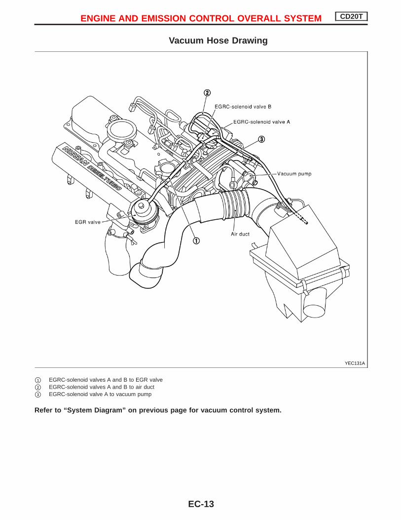
Diagnostic WorksheetThere are many operating conditions that lead to the malfunctionof engine components. A good grasp of such conditions canmake troubleshooting faster and more accurate.In general, each customer feels differently about a problem. It isimportant to fully understand the symptoms or conditions for acustomer complaint.Utilize a diagnostic worksheet like the one shown below in orderto organize all the information for troubleshooting.
WORKSHEET SAMPLE
Customer name MR/MS Model & Year VIN
Engine # Trans. Mileage
Incident Date Manuf. Date In Service Date
Symptoms
l Startability
l Impossible to start l No combustion l Partial combustionl Partial combustion when warming-up enginel Partial combustion when cooling down engine
l Possible but hard to start l Others[ ]
l Idlingl No fast idle l Unstable l High idle l Low idlel Others [ ]
l Driveabilityl Stumble l Surge l Knock l Lack of powerl Others [ ]
l Engine stalll At the time of start l While idlingl While accelerating l While deceleratingl Just after stopping l While loading
Incident occurrencel Just after delivery l Recentlyl In the morning l At night l In the daytime
Frequency l All the time l Under certain conditions l Sometimes
Weather conditions l Not affected
Weatherl Fine l Raining l Snowing l Others[ ]
Temperature l Hot l Warm l Cool l Cold l Humid °F
Engine conditions
l Cold l During warm-up l After warm-up
Engine speed0 2,000 4,000 6,000 8,000 rpm
Road conditions l In town l In suburbs l Highway l Off road (up/down)
Driving conditions
l Not affectedl At starting l While idling l At racingl While accelerating l While cruisingl While decelerating l While turning (RH/LH)
Vehicle speed0 10 20 30 40 50 60 70 80 90 100 mph
Malfunction indicator l Turned on l Not turned on
SEF907L
KEY POINTS
WHAT ..... Vehicle & engine modelWHEN ..... Date, FrequenciesWHERE ..... Road conditionsHOW ..... Operating conditions,
Weather conditions,Symptoms
TROUBLE DIAGNOSIS — Introduction CD20T
EC-34

Work Flow
CHECK IN
Listen to customer complaints. (Get symptoms.) .......................................... STEP I
Check, print out or write down, and erase Diagnostic Trouble (malfunction item)...................................... STEP II
Symptomscollected.
No symptoms, except MIlights up, or MalfunctionCode exists at STEP II.
Verify the symptom by driving in the condition thecustomer described.
H
*1.................................................................................... STEP III
Normal Code(at STEP II)
Malfunction Code(at STEP II)
Verify the malfunction item by performing the “DIAGNOSTIC TROUBLE CON-FIRMATION PROCEDURE”.
*1..................................... STEP IV
EChoose the appropriate action.
Malfunction Code (at STEP II or IV) Normal Code (at both STEP II and IV)
.....................................*2
STEP V
BASIC INSPECTION
SYMPTOM BASIS (at STEP I or III)...........................................................E
Perform inspectionsaccording to SymptomMatrix Chart.
H
TROUBLE DIAGNOSIS FOR SPECIFIC MAL-FUNCTION ITEM.
STEP VI
REPAIR/REPLACE
NG FINAL CHECKConfirm that the incident is completely fixed by performing BASIC INSPECTIONand DIAGNOSTIC TROUBLE CONFIRMATION PROCEDURE (or OVERALLFUNCTION CHECK). Then, erase the unnecessary (already fixed) MalfunctionItem in ECM.
OK
..................................... STEP VII
CHECK OUT
*1: If the incident cannot be duplicated, refer to GI section (“Incident Simulation Tests”, “HOW TO PERFORM EFFICIENTDIAGNOSIS FOR AN ELECTRICAL INCIDENT”).
*2: If the on board diagnostic system cannot be performed, check main power supply and ground circuit. Refer to“TROUBLE DIAGNOSIS FOR MAIN POWER SUPPLY AND GROUND CIRCUIT”, EC-CD-59.
H
H
H
H
H
H
H
H
H
H
H
TROUBLE DIAGNOSIS — Work Flow CD20T
EC-35

Description for Work Flow
STEP DESCRIPTION
STEP IGet detailed information about the conditions and the environment when the incident/symptom occurredusing the “DIAGNOSTIC WORKSHEET” as shown on the previous page.
STEP II
Before confirming the concern, check and write down (print out using CONSULT-II) the malfunction item,then erase the code. The malfunction item can be used when duplicating the incident at STEP III & IV.Study the relationship between the cause, specified by malfunction item, and the symptom described by thecustomer. (The “Symptom Matrix Chart” will be useful. Refer to EC-CD-47.)
STEP III
Try to confirm the symptom and under what conditions the incident occurs.The “DIAGNOSTIC WORK SHEET” is useful to verify the incident. Connect CONSULT-II to the vehicle inDATA MONITOR (AUTO TRIG) mode and check real time diagnosis results.If the incident cannot be verified, perform INCIDENT SIMULATION TESTS. Refer to GI section.If the malfunction code is detected, skip STEP IV and perform STEP V.
STEP IV
Try to detect the malfunction item by driving in (or performing) the “DIAGNOSTIC TROUBLE CONFIRMA-TION PROCEDURE”. Check and read the malfunction item by using CONSULT-II.During the malfunction item verification, be sure to connect CONSULT-II to the vehicle in DATA MONITOR(AUTO TRIG) mode and check real time diagnosis results.If the incident cannot be verified, perform INCIDENT SIMULATION TESTS. Refer to GI section.In case the “DIAGNOSTIC TROUBLE CONFIRMATION PROCEDURE” is not available, perform the “OVER-ALL FUNCTION CHECK” instead. The malfunction item cannot be displayed by this check, however, thissimplified “check” is an effective alternative.The “NG” result of the “OVERALL FUNCTION CHECK” is the same as the DTC detection.
STEP V
Take the appropriate action based on the results of STEP I through IV.If the malfunction code is indicated, proceed to specific TROUBLE DIAGNOSIS for the malfunction item.If the normal code is indicated, proceed to the BASIC INSPECTION. Refer to EC-CD-37. Then performinspections according to the Symptom Matrix Chart. Refer to EC-CD-47.
STEP VI
Identify where to begin diagnosis based on the relationship study between symptom and possible causes.Inspect the system for mechanical binding, loose connectors or wiring damage using (tracing) “Harness Lay-outs”.Gently shake the related connectors, components or wiring harness with CONSULT-II set in “DATA MONI-TOR (AUTO TRIG)” mode.Check the voltage of the related ECM terminals or monitor the output data from the related sensors withCONSULT-II. Refer to EC-CD-52.The “DIAGNOSTIC PROCEDURE” in EC section contains a description based on open circuit inspection. Ashort circuit inspection is also required for the circuit check in the DIAGNOSTIC PROCEDURE. For details,refer to GI section (“Circuit Inspection”, “HOW TO PERFORM EFFICIENT DIAGNOSIS FOR AN ELECTRI-CAL INCIDENT”).Repair or replace the malfunctioning parts.
STEP VII
Once you have repaired the circuit or replaced a component, you need to run the engine in the same condi-tions and circumstances which resulted in the customer’s initial complaint.Perform the “DIAGNOSTIC TROUBLE CONFIRMATION PROCEDURE” and confirm the normal code isdetected. If the incident is still detected in the final check, perform STEP VI by using a different method fromthe previous one.Before returning the vehicle to the customer, be sure to erase the unnecessary (already fixed) malfunctionitem in ECM.
TROUBLE DIAGNOSIS — Work Flow CD20T
EC-36

Basic InspectionPrecaution:Perform Basic Inspection without electrical or mechanicalloads applied; Headlamp switch is off, Air Conditioner switch is off, Rear defogger switch is off, Steering wheel is in the straight-ahead position, etc.
BEFORE STARTING1. Check service records for any
recent repairs that may indicate arelated problem, or the current needfor scheduled maintenance.
2. Open engine hood and check thefollowing:
Harness connectors for faulty con-nections
Vacuum hoses for splits, kinks, orfaulty connections
Wiring for faulty connections,pinches, or cuts
3. Using priming pump, bleed air fromfuel system. Refer to “Fuel FilterCheck” in MA section.
CONNECT CONSULT-II TO THEVEHICLE.Connect “CONSULT-II” to the data linkconnector for CONSULT-II and select“ENGINE” from the menu. Refer to EC-CD-27.
DOES ENGINE START?
Yes
ENo Turn ignition switch to
the “LOCK” position, wait5 seconds and then startengine. If engine fails tostart, check malfunctionitem.
Run engine for 10 minutes.
CHECK IDLE SPEED.Read engine idle speed in“DATA MONITOR” mode withCONSULT-II.825 rpm ± 25 (in N position)
--------------------------------------------------------------------------------------------------------------------------------- OR ---------------------------------------------------------------------------------------------------------------------------------Check idle speed using tachom-eter tester.825 rpm ± 25 (in N position)
(Go to pA on next page.)
SEF142I
SEF671S
Priming pump
SEF689S
.Diesel tacho tester
.Injection tube
PEF190P
H
H
H
H
H
TROUBLE DIAGNOSIS — Basic Inspection CD20T
EC-37

pA
CHECK INJECTION TIMING.1. Set No. 1 piston at TDC on its com-
pression stroke.TDC: Without painted mark
2. Remove injection tubes and airbleeder on the back of injectionpump.
3. Set dial gauge so its indicator pointsto somewhere between 1.0 and 2.0mm (0.039 and 0.079 in) on thescale.
4. Turn crankshaft 2 turns clockwiseand check that dial gauge indicatesthe same value again.
5. Turn crankshaft counterclockwiseabout 100 degrees, then turn crank-shaft slowly clockwise, and set dialgauge indicator to 0 mm at the posi-tion it stops.
6. Turn crankshaft clockwise and set itat plunger lift timing mark using themark on the crankshaft pulley.plunger lift timing mark: Yellowpainted mark
7. Read plunger lift.Plunger lift:
0.89 ± 0.08 mm (0.0350 ± 0.0031in) at plunger lift timing mark
When repeating the checking,start with step 5.
NG
EOK
Bleed air from fuel sys-tem.After this inspection,unnecessary diagnostictrouble code No. mightbe displayed.Erase the storedmemory in ECM.Refer to “ON BOARDDIAGNOSTIC SYSTEMDESCRIPTION”.
OK
INSPECTION END
Adjusting1. If plunger lift is not within the speci-
fied value, adjust by turning injec-tion pump.
If indication is smaller than thespecified value, turn pump bodyaway from engine.
If indication is larger than thespecified value, turn pump bodytowards engine.
2. Tighten injection pump securingbolts and nuts.Nut:
: 20 - 25 N·m(2.0 - 2.6 kg-m, 15 - 18 ft-lb)
Bolt:: 25 - 35 N·m
(2.6 - 3.6 kg-m, 18 - 26 ft-lb)3. Remove dial gauge and install air
bleeder with new washer.4. Install injection tubes.
Flare nut:: 14 - 20 N·m
(1.4 - 2.0 kg-m, 10 - 15 ft-lb)5. Bleed air from fuel system.Refer to “Water Draining, Fuel FilterCheck and Replacement” of“ENGINE MAINTENANCE” in MAsection.
E Go to
SEF661S
SEF655S
Plunger lift timing mark(Yellow painted mark)
TDC (Without painted mark)
SEF662S
IncreaseDecrease
SEF657S
H
H
H
TROUBLE DIAGNOSIS — Basic Inspection CD20T
Basic Inspection (Cont’d)
EC-38

Diagnostic Trouble ChartENGINE RELATED ITEMS
Detected items
(Screen terms for CONSULT-II,“SELF-DIAG RESULTS” mode)
Malfunction is detected when ...
Mass air flow sensor circuit(MASS AIR FLOW SEN)
An excessively high or low voltage from the sensor is detected by the ECM.
Engine coolant temperaturesensor circuit(COOLANT TEMP SEN)
An excessively high or low voltage from the sensor is detected by the ECM.
Vehicle speed sensor circuit orABS actuator and electric unit(control unit) circuit(VEHICLE SPEED SEN)
The almost 0 km/h (0 mph) signal from the sensor is detected by the ECM even whenvehicle is being driven.
Control sleeve position sensorcircuit(CONT SLEEV POS SEN)
An excessively high or low voltage from the sensor is detected by the ECM. An incorrect voltage signal from the sensor is detected by the ECM during engine run-
ning.
Fuel injection feedback 2(F/INJ F/B 2)
The fuel injection feedback system (consists of the ECM, electric governor and controlsleeve position sensor) does not operate properly.
Fuel injection timing feedback(F/INJ TIMG F/B)
The fuel injection timing feedback system (consists of the ECM, fuel injection timing con-trol valve and needle lift sensor) does not operate properly.
Abbreviations for Quick Reference of “DIAGNOSTIC TROUBLE CONFIRMATION PROCEDURE”IGN: ON : Turning the ignition switch ON is required for checking the function of the sensor, switch, solenoid and circuit.RUNNING : Running engine is required for checking the function of the sensor, switch, solenoid and circuit.LIFTING : Lifting up the vehicle, running engine and spinning wheels are required.DRIVING : Driving the vehicle in the specified pattern is required.
Abbreviations for Quick Reference of “OVERALL FUNCTION CHECK”IGN: ON : Turning the ignition switch ON is required for the ECM to detect a malfunction (if one exists).RUNNING : Running engine is required for the ECM to detect a malfunction (if one exists).LIFTING : Lifting up the vehicle, running engine and spinning wheels are required for the ECM to detect a malfunction (if one
exists).DRIVING : Driving the vehicle in the specified pattern is required for the ECM to detect a malfunction (if one exists).
TROUBLE DIAGNOSIS — General Description CD20T
EC-39

—: Not applicable
Check Items(Possible Cause)
*1ConfirmationProcedureQuick Ref.
*2OverallFunctionCheck
MIIllumination
ReferencePage
Harness or connectors(The sensor circuit is open or shorted.)
Mass air flow sensorIGN: ON — — EC-CD-62
Harness or connectors(The sensor circuit is open or shorted.)
Engine coolant temperature sensorIGN: ON — Lighting up EC-CD-66
Harness or connectors(The sensor circuit is open or shorted.)
Vehicle speed sensor or ABS actuator and electric unit(control unit)
— LIFTING — EC-CD-70
Harness or connectors(The sensor circuit is open or shorted.)
Control sleeve position sensorRUNNING — Lighting up EC-CD-74
Main power supply circuit (ECM terminals 23 , 45 ),68 and fuse
Harness or connectors(Electric governor and control sleeve position sensor cir-cuit)
Electronic fuel injection pump ECM Electric governor
RUNNING(DRIVING)
— Lighting up EC-CD-78
Harness or connectors(Injection timing control valve, Needle lift sensor andCrankshaft position sensor (TDC) circuit]
Injection timing control valve Needle lift sensor Crankshaft position sensor Air in fuel line
RUNNING(DRIVING)
— Lighting up EC-CD-82
*1: This is Quick Reference of “DIAGNOSTIC TROUBLE CONFIRMATION PROCEDURE”.Details are described in each TROUBLE DIAGNOSIS.
*2: The “OVERALL FUNCTION CHECK” is a simplified and effective way to inspect a component or circuit.In some cases, the “OVERALL FUNCTION CHECK” is used rather than a “DIAGNOSTIC TROUBLE CONFIRMATION PRO-CEDURE”.When no DIAGNOSTIC TROUBLE CONFIRMATION PROCEDURE is available, the “NG” result of the OVERALL FUNCTIONCHECK can be considered to mean the same as a malfunction item detection.
During an “NG” OVERALL FUNCTION CHECK, the malfunction item might not be confirmed. This is Quick Reference of “OVERALL FUNCTION CHECK”.
Details are described in each TROUBLE DIAGNOSIS.
TROUBLE DIAGNOSIS — General Description CD20T
Diagnostic Trouble Chart (Cont’d)
EC-40

ENGINE RELATED ITEMS
Detected items
(Screen terms forCONSULT-II, “SELF-DIAG
RESULTS” mode)
Malfunction is detected when ...
Cooling fan(OVER HEAT)
An excessive high engine coolant temperature sensor signal is detected by the ECM. (Over-heat)
ECM2(ECM2)
ECM calculation function is malfunctioning.
Needle lift sensor circuit(NEEDLE LIFT SEN)
An incorrect signal from the sensor is detected by the ECM during engine running.
Fuel cut solenoid valve 1(FUEL CUT S/V 1)
Fuel cut solenoid valve circuit is malfunctioning.
Fuel temperature sensorcircuit(FUEL TEMP SENSOR)
An excessively high or low voltage from the sensor is detected by the ECM.
Accelerator position sensorcircuit(ACCEL POS SENSOR)
An excessively high or low voltage from the sensor is detected by the ECM.
Crankshaft position sensor(TDC)[CRANK POS SEN (TDC)]
An incorrect signal from the sensor is detected by the ECM during engine running andcranking.
No failure(NO SELF DIAGNOSTICFAILURE INDICATED)
No malfunction is detected by the ECM.
Abbreviations for Quick Reference of “DIAGNOSTIC TROUBLE CONFIRMATION PROCEDURE”IGN: ON : Turning the ignition switch ON is required for checking the function of the sensor, switch, solenoid and circuit.RUNNING : Running engine is required for checking the function of the sensor, switch, solenoid and circuit.LIFTING : Lifting up the vehicle, running engine and spinning wheels are required.DRIVING : Driving the vehicle in the specified pattern is required.
Abbreviations for Quick Reference of “OVERALL FUNCTION CHECK”IGN: ON : Turning the ignition switch ON is required for the ECM to detect a malfunction (if one exists).RUNNING : Running engine is required for the ECM to detect a malfunction (if one exists).LIFTING : Lifting up the vehicle, running engine and spinning wheels are required for the ECM to detect a malfunction (if one
exists).DRIVING : Driving the vehicle in the specified pattern is required for the ECM to detect a malfunction (if one exists).
TROUBLE DIAGNOSIS — General Description CD20T
Diagnostic Trouble Chart (Cont’d)
EC-41

—: Not applicable
Check Items(Possible Cause)
*1ConfirmationProcedureQuick Ref.
*2OverallFunctionCheck
MIIllumination
ReferencePage
Harness or connectors(The cooling fan circuit is open or shorted.)
Cooling fan Radiator hose Radiator Radiator cap Water pump Thermostat Fan belt Engine coolant temperature sensorFor more information, refer to “12 MAIN CAUSES OFOVERHEATING”. (EC-CD-95)
—IGN: ON
(RUNNING)Lighting up EC-CD-78
ECMIGN: ON — Lighting up EC-CD-86
Harness or connectors(The sensor circuit is open or shorted.)
Needle lift sensor Air in fuel line Clogging No. 1 injection nozzle
RUNNING — Lighting up EC-CD-97
Harness or connectors(The solenoid valve circuit is open or shorted.)
Fuel cut solenoid valveRUNNING — Lighting up EC-CD-100
Harness or connectors(The sensor circuit is open or shorted.)
Fuel temperature sensorIGN: ON — — EC-CD-104
Harness or connectors(The sensor circuit is open or shorted.)
Accelerator position sensor Accelerator position switch
IGN: ON — Lighting up EC-CD-108
Harness or connectors(The sensor circuit is open or shorted.)
Crankshaft position sensor (TDC)RUNNING — Lighting up EC-CD-114
No failure— — — —
*1: This is Quick Reference of “DIAGNOSTIC TROUBLE CONFIRMATION PROCEDURE”.Details are described in each specific TROUBLE DIAGNOSIS.
*2: The “OVERALL FUNCTION CHECK” is a simplified and effective way to inspect a component or circuit.In some cases, the “OVERALL FUNCTION CHECK” is used rather than a “DIAGNOSTIC TROUBLE CONFIRMATION PRO-CEDURE”.When no DIAGNOSTIC TROUBLE CONFIRMATION PROCEDURE is available, the “NG” result of the OVERALL FUNCTIONCHECK can be considered to mean the same as a malfunction item detection.
During an “NG” OVERALL FUNCTION CHECK, the malfunction item might not be confirmed. This is Quick Reference of “OVERALL FUNCTION CHECK”.
Details are described in each specific TROUBLE DIAGNOSIS.
TROUBLE DIAGNOSIS — General Description CD20T
Diagnostic Trouble Chart (Cont’d)
EC-42

ENGINE RELATED ITEMS
Detected items
(Screen terms forCONSULT-II, “SELF-DIAG
RESULTS” mode)
Malfunction is detected when ...
Atmospheric pressuresensor *5(—) *3
An excessively high or low voltage from the sensor is detected by the ECM.
Glow relay circuit(GLOW RELAY)
Glow relay circuit is open or shorted.
ECM(—)*3
ECM reference voltage (2.5V) is excessively high or low.
Air conditioner relay circuit(—)*3
Air conditioner relay circuit is shorted.
EGRC-solenoid valve A(EGR SYS)
EGRC-solenoid valve A is open or shorted.
Brake switch circuits(—)*3
Brake switch circuits are open or shorted.
ECM(—)*3
ECM version number or switching function is not plausible.
ECCS-D relay circuit(—)*3
ECCS-D relay shut-off time is too late.
Ignition switch “ON” signalcircuit(—)*3
Ignition switch “ON” signal evaluation circuit in ECM is malfunctioning.
Injection timing controlvalve circuit(INJ TIMING CONT/V)
Injection timing control valve circuit is open or shorted.
Camshaft position sensor(PUMP)*4(—)*3
An improper signal is calculated by the ECM.
Abbreviations for Quick Reference of “DIAGNOSTIC TROUBLE CONFIRMATION PROCEDURE”IGN: ON : Turning the ignition switch ON is required for checking the function of the sensor, switch, solenoid and circuit.RUNNING : Running engine is required for checking the function of the sensor, switch, solenoid and circuit.LIFTING : Lifting up the vehicle, running engine and spinning wheels are required.DRIVING : Driving the vehicle in the specified pattern is required.
Abbreviations for Quick Reference of “OVERALL FUNCTION CHECK”IGN: ON : Turning the ignition switch ON is required for the ECM to detect a malfunction (if one exists).RUNNING : Running engine is required for the ECM to detect a malfunction (if one exists).LIFTING : Lifting up the vehicle, running engine and spinning wheels are required for the ECM to detect a malfunction (if one
exists).DRIVING : Driving the vehicle in the specified pattern is required for the ECM to detect a malfunction (if one exists).
TROUBLE DIAGNOSIS — General Description CD20T
Diagnostic Trouble Chart (Cont’d)
EC-43

—: Not applicable
Check Items(Possible Cause)
*1ConfirmationProcedureQuick Ref.
*2Overall Func-tion Check
MIIllumination
ReferencePage
ECMIGN: ON — — EC-CD-86
Harness or connectors(The glow relay circuit is open or shorted.)
Glow relayIGN: ON — — EC-CD-118
ECMIGN: ON — — EC-CD-86
Harness or connectors(The air conditioner relay circuit is open or shorted.)
Air conditioner relayIGN: ON — — EC-CD-126
Harness or connectors(The EGRC-solenoid valve A circuit is open or shorted.)
EGRC-solenoid valveRUNNING — Lighting up EC-CD-129
Harness or connectors(Brake switch circuits are open or shorted.)
Brake lamp switch RDNT brake switch
RUNNING — Lighting up EC-CD-136
ECMIGN: ON — — EC-CD-86
Harness or connectors(The ECCS-D relay circuit is shorted.)
ECCS-D relay ECM
IGN: ON — Lighting up EC-CD-86
ECMIGN: ON — Lighting up EC-CD-86
Harness or connectors(The injection timing control valve circuit is open orshorted.)
Injection timing control valve
IGN: ON — Lighting up EC-CD-82
ECM Needle lift sensor Low battery voltage
RUNNING — Lighting up EC-CD-97
*1: This is Quick Reference of “DIAGNOSTIC TROUBLE CONFIRMATION PROCEDURE”.Details are described in each specific TROUBLE DIAGNOSIS.
*2: The “OVERALL FUNCTION CHECK” is a simplified and effective way to inspect a component or circuit.In some cases, the “OVERALL FUNCTION CHECK” is used rather than a “DIAGNOSTIC TROUBLE CONFIRMATION PRO-CEDURE”.When no DIAGNOSTIC TROUBLE CONFIRMATION PROCEDURE is available, the “NG” result of the OVERALL FUNCTIONCHECK can be considered to mean the same as a malfunction item detection.
During an “NG” OVERALL FUNCTION CHECK, the malfunction item might not be confirmed. This is Quick Reference of “OVERALL FUNCTION CHECK”.
Details are described in each specific TROUBLE DIAGNOSIS.*3: CONSULT-II may not detect, but self-diagnostic results are available with MI.*4: Imaginary sensor, which produces secondary engine revolution signal using needle lift sensor pulse.*5: The atmospheric pressure sensor is located inside the ECM and is not replaceable.
TROUBLE DIAGNOSIS — General Description CD20T
Diagnostic Trouble Chart (Cont’d)
EC-44

ENGINE RELATED ITEMS
Detected items
(Screen terms forCONSULT-II, “SELF-DIAG
RESULTS” mode)
Malfunction is detected when ...
MI(—)*3
MI (malfunction indicator) circuit is open or shorted.
GLOW LAMP CIRCUIT(—)*3
Glow lamp circuit is open or shorted.
Abbreviations for Quick Reference of “DIAGNOSTIC TROUBLE CONFIRMATION PROCEDURE”IGN: ON : Turning the ignition switch ON is required for checking the function of the sensor, switch, solenoid and circuit.RUNNING : Running engine is required for checking the function of the sensor, switch, solenoid and circuit.LIFTING : Lifting up the vehicle, running engine and spinning wheels are required.DRIVING : Driving the vehicle in the specified pattern is required.
Abbreviations for Quick Reference of “OVERALL FUNCTION CHECK”IGN: ON : Turning the ignition switch ON is required for the ECM to detect a malfunction (if one exists).RUNNING : Running engine is required for the ECM to detect a malfunction (if one exists).LIFTING : Lifting up the vehicle, running engine and spinning wheels are required for the ECM to detect a malfunction (if one
exists).DRIVING : Driving the vehicle in the specified pattern is required for the ECM to detect a malfunction (if one exists).
TROUBLE DIAGNOSIS — General Description CD20T
Diagnostic Trouble Chart (Cont’d)
EC-45

—: Not applicable
Check Items(Possible Cause)
*1ConfirmationProcedureQuick Ref.
*2Overall Func-tion Check
MIIllumination
ReferencePage
Harness or connectors(The MI circuit is open or shorted.)
MI lamp ECM
IGN: ON — — EC-CD-141
Harness or connectors(The glow indicator lamp circuit is open or shorted.)
Glow lampIGN: ON — — EC-CD-118
*1: This is Quick Reference of “DIAGNOSTIC TROUBLE CONFIRMATION PROCEDURE”.Details are described in each specific TROUBLE DIAGNOSIS.
*2: The “OVERALL FUNCTION CHECK” is a simplified and effective way to inspect a component or circuit.In some cases, the “OVERALL FUNCTION CHECK” is used rather than a “DIAGNOSTIC TROUBLE CONFIRMATION PRO-CEDURE”.When no DIAGNOSTIC TROUBLE CONFIRMATION PROCEDURE is available, the “NG” result of the OVERALL FUNCTIONCHECK can be considered to mean the same as a malfunction item detection.
During an “NG” OVERALL FUNCTION CHECK, the malfunction item might not be confirmed. This is Quick Reference of “OVERALL FUNCTION CHECK”.
Details are described in each specific TROUBLE DIAGNOSIS.*3: CONSULT-II may not detect, but self-diagnostic results are available with MI.
TROUBLE DIAGNOSIS — General Description CD20T
Diagnostic Trouble Chart (Cont’d)
EC-46

Symptom Matrix Chart
SYSTEM— Basic enginecontrol system
SYMPTOM
Ref
eren
cepa
ge
Fea
ture
ofsy
mpt
om,
Che
ckpo
int
HA
RD
/NO
STA
RT
/RE
STA
RT
(EX
CP.
HA
)
EN
GIN
ES
TALL
HE
SIT
AT
ION
/SU
RG
ING
/FLA
TS
PO
T
SP
AR
KK
NO
CK
/DE
TO
NA
TIO
N
LAC
KO
FP
OW
ER
PO
OR
AC
CE
LER
AT
ION
HI
IDLE
LOW
IDLE
RO
UG
HID
LE/H
UN
TIN
G
IDLI
NG
VIB
RA
TIO
N
SLO
W/N
OR
ET
UR
NT
OID
LE
OV
ER
HE
AT
/HIG
HE
NG
INE
CO
OLA
NT
TE
MP
ER
AT
UR
E
EX
CE
SS
IVE
FU
EL
CO
NS
UM
PT
ION
EX
CE
SS
IVE
OIL
CO
NS
UM
PT
ION AB
NO
RM
AL
SM
OK
EC
OLO
R
DE
AD
BA
TT
ER
Y(U
ND
ER
CH
AR
GE
)
Mal
func
tion
indi
cato
rill
umin
ates
.
Can
bede
tect
edby
CO
NS
ULT
-II?
Fue
lcut
NO
STA
RT
(with
first
firin
g)
NO
STA
RT
(with
out
first
firin
g)
HA
RD
TO
STA
RT
WH
EN
EN
GIN
EIS
CO
LD
HA
RD
TO
STA
RT
WH
EN
EN
GIN
EIS
HO
T
AT
IDLE
DU
RIN
GD
RIV
ING
WH
EN
DE
CE
LER
AT
ING
BLA
CK
SM
OK
E
WH
ITE
SM
OK
ENew CT/CS AA AB AC AD AE AF AG AH AJ AK AL AM AP HA
Injec-tiontiming
Advanced q q q q q q EC-CD-38
Retarded q q q q q q EC-CD-38
Electric injectionpump mainframe
q q q q q q q q q q q q q q — *1
Injection nozzle q q q q q q q q q q EC-CD-22 *2
Glow system q q EC-CD-118
Engine body q q q q q q q q q q q EM-
section*3
EGR system EC-CD-129
Air cleaner andducts
q MA-section
*4
; High Possibility Itemq; Low Possibility Item*1: Insufficient or excess amount. Governor malfunction may be the cause.*2: Depends on open-valve pressure and spray pattern.*3: Caused mainly by insufficient compression pressure.*4: Symptom varies depending on off-position of air duct, etc.
TROUBLE DIAGNOSIS — General Description CD20T
EC-47

SYSTEM — Engine control module system
Malfunction
SY
MP
TO
M
Reference page
Feature of symptomCheck point
HARD/NO START/RESTART (EXCP. HA)
ENGINE STALL
HESITATION/SURGING/FLAT SPOT
SPARK KNOCK/DETONATION
LACK OF POWER
POOR ACCELERATION
HI IDLE
LOW IDLE
ROUGH IDLE/HUNTING
IDLING VIBRATION
SLOW/NO RETURN TO IDLE
OVERHEAT/HIGH ENGINE COOLANT TEMPERATURE
EXCESSIVE FUEL CONSUMPTION
EXCESSIVE OIL CONSUMPTION
ABNORMAL SMOKE COLOR
DEAD BATTERY (UNDER CHARGE)
Malfunction indicator illuminates.
Can be detected by CONSULT-II?
Fuel cut
NO START (with first firing)
NO START (without first firing)
HARD TO START WHEN ENGINE IS COLD
HARD TO START WHEN ENGINE IS HOT
AT IDLE
DURING DRIVING
WHEN DECELERATING
BLACK SMOKE
WHITE SMOKE
New
CT
/CS
AA
AB
AC
AD
AE
AF
AG
AH
AJ
AK
AL
AM
AP
HA
Engine control module
Mas
sai
rflo
wse
nsor
circ
uit
open
,gr
ound
shor
tq
qE
C-C
D-6
2sh
ort
q
Eng
ine
cool
ant
tem
pera
ture
sens
orci
rcui
top
en,
shor
tq
qE
C-C
D-6
6C
ompe
nsat
ion
acco
rdin
gto
engi
neco
olan
tte
mpe
ratu
redo
esno
tfu
nctio
n.
Veh
icle
spee
dse
nsor
circ
uit
orA
BS
actu
ator
and
elec
tric
unit
(con
trol
unit)
circ
uit
open
,sh
ort
EC
-CD
-70
Con
trol
slee
vepo
sitio
nse
nsor
cir-
cuit
open
,sh
ort
EC
-CD
-74
Ele
ctric
gove
rnor
circ
uit
open
,gr
ound
shor
tq
EC
-CD
-78
shor
tq
q
Inje
ctio
ntim
ing
cont
rolv
alve
circ
uit
open
,sh
ort
EC
-CD
-82
Inje
ctio
ntim
ing
cann
otbe
cont
rolle
d.
grou
ndsh
ort
qN
eedl
elif
tse
nsor
circ
uit
open
,sh
ort
EC
-CD
-97
Fue
lcut
sole
noid
valv
eci
rcui
top
en,
grou
ndsh
ort
qE
C-C
D-1
00sh
ort
qE
ngin
eru
nson
afte
rtu
rnin
gig
nitio
nsw
itch
OF
F.
Fue
ltem
pera
ture
sens
orci
rcui
top
en,
shor
tq
qE
C-C
D-1
04
Com
pens
atio
nfo
ram
ount
offu
elin
ject
edac
cord
ing
tofu
elte
mpe
ratu
redo
esno
tfu
nctio
n.
Acc
eler
ator
posi
tion
sens
orci
rcui
top
en,
shor
tq
EC
-CD
-108
Cra
nksh
aft
posi
tion
sens
or(T
DC
)ci
rcui
top
en,
shor
tq
qE
C-C
D-1
14no
ise
q
TROUBLE DIAGNOSIS — General Description CD20T
Symptom Matrix Chart (Cont’d)
EC-48

SYSTEM — Engine control module system
Malfunction
SY
MP
TO
M
Reference page
Feature of symptomCheck point
HARD/NO START/RESTART (EXCP. HA)
ENGINE STALL
HESITATION/SURGING/FLAT SPOT
SPARK KNOCK/DETONATION
LACK OF POWER
POOR ACCELERATION
HI IDLE
LOW IDLE
ROUGH IDLE/HUNTING
IDLING VIBRATION
SLOW/NO RETURN TO IDLE
OVERHEAT/HIGH ENGINE COOLANT TEMPERATURE
EXCESSIVE FUEL CONSUMPTION
EXCESSIVE OIL CONSUMPTION
ABNORMAL SMOKE COLOR
DEAD BATTERY (UNDER CHARGE)
Malfunction indicator illuminates.
Can be detected by CONSULT-II?
Fuel cut
NO START (with first firing)
NO START (without first firing)
HARD TO START WHEN ENGINE IS COLD
HARD TO START WHEN ENGINE IS HOT
AT IDLE
DURING DRIVING
WHEN DECELERATING
BLACK SMOKE
WHITE SMOKE
New
CT
/CS
AA
AB
AC
AD
AE
AF
AG
AH
AJ
AK
AL
AM
AP
HA
Engine control module
Sta
rtsi
gnal
circ
uit
open
,sh
ort
EC
-CD
-145
Sta
rtco
ntro
ldoe
sno
tfu
nctio
n.
Air
cond
ition
ersw
itch
circ
uit
open
,gr
ound
shor
tE
C-C
D-1
26A
irco
nditi
oner
does
not
stop
oper
atin
g.sh
ort
Air
cond
ition
erdo
esno
tw
ork.
Acc
eler
ator
posi
tion
switc
h(I
dle)
circ
uit
open
,gr
ound
shor
tq
EC
-CD
-108
shor
tq
Acc
eler
ator
posi
tion
sens
orN
Gsi
gnal
isou
tput
.
Igni
tion
switc
hci
rcui
t(O
Nsi
gnal
)op
enq
qE
C-C
D-5
9sh
ort
Eng
ine
does
not
stop
.
Pow
ersu
pply
for
EC
Mci
rcui
top
enq
EC
-CD
-59
shor
tq
q
EG
RC
-sol
enoi
dva
lve
circ
uit
open
,sh
ort
EC
-CD
-129
grou
ndsh
ort
qD
oes
not
stop
oper
atin
g.
Glo
wre
lay
circ
uit
open
qE
C-C
D-1
18G
low
lam
pdo
esno
ttu
rnon
.sh
ort
Glo
wla
mp
does
not
turn
off.
Eng
ine
cont
rolm
odul
ere
lay
(Sel
f-sh
utof
f)ci
rcui
t
open
EC
-CD
-59
shor
tq
Gro
und
shor
tm
akes
engi
neun
able
tost
op.
Air
cond
ition
erre
lay
circ
uit
open
EC
-CD
-126
Air
cond
ition
erdo
esno
top
er-
ate.
shor
tq
qA
irco
nditi
oner
does
not
stop
oper
atin
g.
Bra
kesw
itch
circ
uits
open
qE
C-C
D-1
36sh
ort
qE
CM
,C
onne
ctor
circ
uit
open
,sh
ort
qE
C-C
D-8
6
TROUBLE DIAGNOSIS — General Description CD20T
Symptom Matrix Chart (Cont’d)
EC-49

CONSULT-II Reference Value in Data MonitorMode
Remarks: Specification data are reference values. Specification data are output/input values which are detected or supplied by the ECM at the connector.
* Specification data may not be directly related to their components signals/values/operations.
MONITOR ITEM CONDITION SPECIFICATION
CKPS⋅RPM (TDC) Tachometer: Connect Run engine and compare tachometer indication with the CONSULT-II value.
Almost the same speed as the CON-SULT-II value.CKPS⋅RPM-PUMP
COOLAN TEMP/S Engine: After warming up More than 70°C (158°F)
VHCL SPEED SE Turn drive wheels and compare speedometer indication with the CON-
SULT-II valueAlmost the same speed asthe CONSULT-II value
FUEL TEMP SEN Engine: After warming up More than 40°C (104 °F)
ACCEL POS SEN Ignition switch: ON
(Engine stopped)
Accelerator pedal: release Approx. 0.40V
Accelerator pedal: depress Approx. 3.3V
OFF ACCEL POS Ignition switch: ON
(Engine stopped)
Accelerator pedal: release ON
Accelerator pedal: slightly open OFF
C/SLEEV POS/S Engine: After warming up Approx. 2.5V
BATTERY VOLT Ignition switch: ON (Engine stopped) 11 - 14V
START SIGNAL Ignition switch: ON , START , ON OFF , ON , OFF
AIR COND SIG Engine: After warming up, idle the
engine
Air conditioner switch: “OFF” OFF
Air conditioner switch: “ON”(Compressor operates.)
ON
IGN SW Ignition switch: ON , OFF ON , OFF
MAS AIR/FL SE
Engine: After warming up Air conditioner switch: “OFF” Shift lever: “N” No-load
Idle 0.8 - 2.7V
2,000 rpm 2.2 - 2.8V
ACT INJ TIMG
Engine: After warming up Air conditioner switch: “OFF” Shift lever: “N” No-load At sea level
Idle -0.5 to -1.5°
2,000 rpm +2.5° to +3.5°
TARGET F/INJ
Engine: After warming up Air conditioner switch: “OFF” Shift lever: “N” No-load At sea level
Idle 8.0 - 8.8 mm3/stroke
2,000 rpm Approx. 7.6 mm3/stroke
BRAKE SW Ignition switch: ONBrake pedal: released OFF
Brake pedal: depressed ON
BRAKE SW 2 Ignition switch: ONBrake pedal: released OFF
Brake pedal: depressed ON
FUEL CUT S/V Ignition switch: ON , OFF ON , OFF
AIR COND RLY Air conditioner switch: OFF , ON OFF , ON
GLOW RLY Refer to EC-CD-124.
COOLING FAN
When cooling fan is stopped. OFF
When cooling fan operates at low speed. LOW
When cooling fan operates at high speed. HI
EGRC SOL/V A
Engine: After warming up Air conditioner switch: “OFF” Shift lever: “N” No-load At sea level
Idle OFF
2,800 rpm ON
TROUBLE DIAGNOSIS — General Description CD20T
EC-50

Major Sensor Reference Graph in DataMonitor Mode
The following are the major sensor reference graphs in “DATA MONITOR” mode.(Select “HI SPEED” in “DATA MONITOR” with CONSULT-II.)
ACCEL POS SEN, C/SLEEV POS/S, ACT INJ TIMGBelow is the data for “ACCEL POS SEN”, “C/SLEEV POS/S” and “ACT INJ TIMG” when revving enginequickly up to 3,000 rpm under no load after warming up engine sufficiently.Each value is for reference, the exact value may vary.
NEF780
“ACCEL POS SEN” should increasewhile depressing the acceleratorpedal and should decrease whilereleasing it.
“C/SLEEV POS/S” should increasewhen depressing the acceleratorpedal and should decrease when the pedal isreleased.
“ACT INJ TIMG” should increasewhen depressing the acceleratorpedal and should decrease whenthe pedal is released.
AC
TIN
JT
IMG
13:2
2-0
0”09
+04
”95
16:0
6x0
.1V
-00”
09+
04”9
516
:06
x0.1
V-0
0”09
+04
”95
TROUBLE DIAGNOSIS — General Description CD20T
EC-51

ECM Terminals and Reference ValuePREPARATIONThe ECM is located beneath the heater unit. To access the ECM,remove the center console under cover at the passenger side.Perform all voltage measurements with all connectors con-nected. Since the ECM harness connector cannot be accessedfrom the backside, voltages should be measured by connectinga break out box (SST) between ECM and ECM harness connec-tor.
When measuring: Use extreme care not to touch 2 pins at the same time. Note that the data is for comparison and may not be exact. Be sure ECM unit is properly grounded before checking.
SEF883Y
NEF162A
ECM
Y-adapter
Breakout box
Y-adapter
To ECM har-ness connec-tor
TROUBLE DIAGNOSIS — General Description CD20T
EC-52

ECM INSPECTION TABLESpecification data are reference values and are measured between each terminal and ground.CAUTION:Do not use ECM ground terminals when measuring input/output voltage. Doing so may result indamage to the ECM’s transistor. Use a ground other than ECM terminals, such as the ground.
TER-MINAL
NO.
WIRECOLOR
ITEM CONDITIONDATA
(DC Voltage andPulse Signal)
101102103
B/L Electric governor ground
Engine is running. (Warm-up condition)
Idle speed
qApproximately 10.5V
SEF562S
Engine is running. (Warm-up condition)
Engine speed is 2,000 rpm
Approximately 10.5
SEF563S
104105106
B ECM groundEngine is running.
Idle speed
Engine ground(Probe this terminal with@ tester probe whenmeasuring.)
107108109
R Power supply for ECM Ignition switch “ON”BATTERY VOLTAGE(11 - 14V)
202 B/WInjection timing controlvalve
Engine is running. (Warm-up condition)
Idle speed
Approximately 9V
SEF564S
Engine is running. (Warm-up condition)
Engine speed is 2,000 rpm
Approximately 8V
SEF565S
TROUBLE DIAGNOSIS — General Description CD20T
ECM Terminals and Reference Value (Cont’d)
EC-53

TER-MINAL
NO.
WIRECOLOR
ITEM CONDITIONDATA
(DC Voltage andPulse Signal)
204 L/W Air conditioner relay
Engine is running.
Both A/C switch and blower switch are“ON”
Approximately 0.4V
Engine is running.
A/C switch is “OFF”
BATTERY VOLTAGE(11 - 14V)
208 P EGRC-solenoid valve A
Engine is running. (Warm-up condition)
Idle speed
BATTERY VOLTAGE (11- 14V)
Engine is running. (Warm-up condition)
Engine speed is 2,800 rpmApproximately 0.3V
214 W/R Glow relay Refer to “Glow control System”.
215 OR/L Malfunction indicator
Ignition switch “ON” Approximately 1.0V
Engine is running.
Idle speed
BATTERY VOLTAGE(11 - 14V)
218 ORMass air flow sensorground
Engine is running.
Idle speedApproximately 0V
219 LG/RCooling fan relay(Low speed)
Engine is running.
Cooling fan is not operating.
BATTERY VOLTAGE(11 - 14V)
Engine is running.
Cooling fan is operating.Approximately 0.4V
220 LGCooling fan relay(High speed)
Engine is running.
Cooling fan is not operating.Cooling fan is operating at low speed.
BATTERY VOLTAGE(11 - 14V)
Engine is running.
Cooling fan is operating at high speed.Approximately 0.5V
221 P/L Glow lamp
Ignition switch “ON”
Glow lamp is “ON”.Approximately 1.0V
Ignition switch “ON”
Glow lamp is “OFF”
BATTERY VOLTAGE(11 - 14V)
223 W/LMass air flow sensorpower supply Ignition switch “ON” Approximately 5V
224 L/W Mass air flow sensor
Engine is running. (Warm-up condition)
Idle speed1.9 - 2.3V
Engine is running. (Warm-up condition)
Engine speed is 2,000 rpm2.5 - 2.9V
TROUBLE DIAGNOSIS — General Description CD20T
ECM Terminals and Reference Value (Cont’d)
EC-54

TER-MINAL
NO.
WIRECOLOR
ITEM CONDITIONDATA
(DC Voltage andPulse Signal)
320 WControl sleeve positionsensor power supply
Engine is running.
Idle speed
Approximately 2.6V
SEF559S
321 BControl sleeve positionsensor ground
Engine is running.
Idle speed
Approximately 2.6V
SEF560S
322 RControl sleeve positionsensor (Reference sig-nal)
Engine is running. (Warm-up condition)
Idle speed
Approximately 2.6V
SEF561S
325 W/GEngine control modulerelay (Self-shutoff)
Engine is running.
Ignition switch “LOCK”
For a few seconds after turning ignitionswitch to the “LOCK” position
0 - 1V
Ignition switch “LOCK”
Following a few seconds delay after turningignition switch to the “LOCK” position
BATTERY VOLTAGE(11 - 14V)
331 ORCrankshaft position sen-sor (TDC) ground
Engine is running.
Idle speedApproximately 0V
333 BNeedle lift sensorground Ignition switch “ON” Approximately 0V
334335436
B Sensors’ groundEngine is running.
Idle speedApproximately 0V
TROUBLE DIAGNOSIS — General Description CD20T
ECM Terminals and Reference Value (Cont’d)
EC-55

TER-MINAL
NO.
WIRECOLOR
ITEM CONDITIONDATA
(DC Voltage andPulse Signal)
344 WCrankshaft position sen-sor (TDC) (Signal)
Engine is running. (Warm-up condition)
Idle speed
Approximately 0V
NEF867
Engine is running.
Engine speed is 2,000 rpm
Approximately 0V
NEF868
345 W Needle lift sensor
Engine is running. (Warm-up condition)
Idle speed
Approximately 3.8 - 4.0V
NEF869
Engine is running. (Warm-up condition)
Engine speed is 2,000 rpm
Approximately 3.8 - 4.0V
NEF870
347 L/BEngine coolant tempera-ture sensor Engine is running.
0.6 - 4.8VOutput voltage varieswith engine coolant tem-perature.
348411
R/Y Fuel temperature sensor Engine is running.0.6 - 4.8VOutput voltage varieswith fuel temperature.
349 SB Fuel cut solenoid valve
Ignition switch “LOCK” Approximately 0V
Ignition switch “ON”BATTERY VOLTAGE(11 - 14V)
TROUBLE DIAGNOSIS — General Description CD20T
ECM Terminals and Reference Value (Cont’d)
EC-56

TER-MINAL
NO.
WIRECOLOR
ITEM CONDITIONDATA
(DC Voltage andPulse Signal)
403 GY Air conditioner switch
Engine is running.
Both air conditioner switch and blowerswitch are “ON” (Compressor operates)
Approximately 0V
Engine is running.
Air conditioner switch is “OFF”
BATTERY VOLTAGE(11 - 14V)
405 R/G Stop lamp switch
Ignition switch “ON”
Brake pedal released0V
Ignition switch “ON”
Brake pedal depressed
Battery voltage(11 - 14V)
410 ORImmobilizer communica-tion Ignition switch “ON”
BATTERY VOLTAGE(4 - 14V)
416 R/B Brake switch 2
Ignition switch “ON”
Brake pedal released
Battery voltage(11 -14V)
Ignition switch “ON”
Brake pedal depressed0V
417 OR/WVehicle speed sensor orABS actuator and elec-tric unit (control unit)
Engine is running.
Lift up the vehicle.In 2nd gear positionVehicle speed is 40 km/h (25 mph)
0 - Approximately 4.2V
SEF552S
420 BR/WData link connector forCONSULT-II
Engine is running.
Idle speed (CONSULT-II is connected andturned on)
Approximately 4 - 9V
415 G/R Approximately 0V
425 BRAccelerator position sen-sor ground
Engine is running.
Idle speedApproximately 0V
433 LG/WAccelerator position sen-sor power supply Ignition switch “ON” Approximately 5V
434 W/PUAccelerator position sen-sor
Ignition switch “ON”
Accelerator pedal released0.4 - 0.6V
Ignition switch “ON”
Accelerator pedal fully depressedApproximately 4.0V
TROUBLE DIAGNOSIS — General Description CD20T
ECM Terminals and Reference Value (Cont’d)
EC-57

TER-MINAL
NO.
WIRECOLOR
ITEM CONDITIONDATA
(DC Voltage andPulse Signal)
435 GY/RAccelerator positionswitch (Idle)
Ignition switch “ON”
Accelerator pedal releasedApproximately 0V
Ignition switch “ON”
Accelerator pedal depressedApproximately 2.7V
442 B/Y Start signal
Ignition switch “ON” Approximately 0V
Ignition switch “START”BATTERY VOLTAGE(11 - 14V)
439 L/OR Tachometer
Engine is running. (Warm-up condition)
Idle speed
Approximately 1.1 - 1.5V
SEF550S
Engine is running.
Engine speed is 2,000 rpm
Approximately 1.1 - 1.5V
SEF551S
507 BR/Y Ignition switch
Ignition switch “LOCK” 0V
Ignition switch “ON”BATTERY VOLTAGE(11 - 14V)
TROUBLE DIAGNOSIS — General Description CD20T
ECM Terminals and Reference Value (Cont’d)
EC-58

Main Power Supply and Ground Circuit
YEC100A
TROUBLE DIAGNOSIS FOR POWER SUPPLY CD20T
EC-59

INSPECTION START
Start engine.Is engine running?
Yes
ENo CHECK POWER SUPPLY-I.
1. Disconnect ECM harnessconnector.
2. Turn ignition switch to“ON” position.
3. Check voltage betweenECM connector terminal
507 and groundVoltage: Battery voltage
If NG, check the following: 10A fuse Harness connectors
M52 , F103
Harness for open orshort-circuit betweenECM and ignition switch.
If NG, replace 10A fuse orrepair harness or connec-tors.
OK
1. Stop engine.2. Disconnect ECM harness connector.3. Turn ignition switch to “ON” position.
F
CHECK POWER SUPPLY-II.1. Short between ECM connector terminal
325 and engine ground with a jumpwire.
2. Check voltage between ECM terminals107 , 108 , 109 and ground.
Voltage: Battery voltage
NG
EOK Go to “CHECK
GROUND CIRCUIT” onpage EC-CD-61.
CHECK HARNESS CONTINUITYBETWEEN ENGINE CONTROL MODULERELAY AND ECMCheck harness continuity between ECMconnector terminals 107 , 108 , 109 andECM relay connector terminal p5 .Continuity should exist.If OK, check harness for short.
OK
ENG Check the following:
Harness connectorsM89 , F96
Harness for open orshort-circuit betweenECM relay and ECM.
If NG, repair harness orconnectors.
pA
NEF863
YEC327ECM relay
NEF186A
NEF187A
NEF188A
ECM relayconnector
H
H
H
H
H
TROUBLE DIAGNOSIS FOR POWER SUPPLY CD20T
Main Power Supply and Ground Circuit(Cont’d)
EC-60

pA
CHECK VOLTAGE BETWEEN ENGINECONTROL MODULE RELAY ANDGROUND.Check voltage between ECM relay connec-tor terminals p2 , p3 and ground withCONSULT-II or tester.Voltage: Battery voltage
OK
ENG Check the following:
15A fuse Harness for open or
short-circuit betweenECM relay and battery.
If NG, replace fuse or repairharness or connectors.
CHECK OUTPUT SIGNAL CIRCUIT.Check harness continuity between ECMconnector terminal 325 and ECM relayconnector terminal p1 .Continuity should exist.If OK, check harness for short-circuit.
OK
ENG
Check harness connec-tors E43 , F2
Repair harness or connec-tors.
CHECK ECM RELAY.1. Apply 12V direct current between ECM
relay connector terminals p1 and p2 .2. Check continuity between engine control
module relay connector terminals p3 and
p5 .12V (p1 - p2 ) applied:
Continuity exists.No voltage applied:
No continuity
OK
ENG Replace ECM relay.
CHECK GROUND CIRCUIT.1. Turn ignition switch to “LOCK” position.2. Check harness continuity between ECM
connector terminals 104 , 105 , 106
and engine ground.Continuity should exist.If resistance is too high, loosen, clean andretighten engine ground.If OK, check harness for short-circuit.
OK
ENG Repair harness or connec-
tors.
Check ECM pin terminals for damage andcheck the connection of ECM harness con-nector.
INSPECTION END
YEC352
ECM relayconnector
NEF189A
ECM relayconnector
YEC354
ECM relayconnector
NEF190A
NEF399Engine ground
H
H
H
H
H
H
TROUBLE DIAGNOSIS FOR POWER SUPPLY CD20T
Main Power Supply and Ground Circuit(Cont’d)
EC-61

Mass Air Flow Sensor (MAFS)The mass air flow sensor measures the amount of intake air byanalysing a part of the entire flow. When intake air flows into theintake manifold, heat is withdrawn from the hot film. By regulat-ing the electrical current that flows through the hot film, the ECMmaintains the hot film temperature on a constant level. Theamount of electric current that is needed to keep the hot film ona constant temperature level is proportional to the mass of airthat flows into the engine.
Malfunction is detected when . . .Check Items
(Possible Cause)
An excessively high or low voltage from the sensor isentered to ECM.
Harness or connectors(The sensor circuit is open or shorted.)
Mass air flow sensor
DIAGNOSTIC TROUBLE CONFIRMATIONPROCEDURE
1) Turn ignition switch to “ON” position.2) Select “DATA MONITOR” mode with CONSULT-II.3) Start engine and wait for at least 20 seconds.
NEF663
TROUBLE DIAGNOSIS 1 CD20T
EC-62

YEC799
BATTERY
Refer to EL-POWER. : Detectable line for DTC: Non-detectable line for DTC
ENGINECONTROLMODULERELAY
MASS AIRFLOW SEN-SOR
ECM
TROUBLE DIAGNOSIS 1 CD20T
Mass Air Flow Sensor (MAFS) (Cont’d)
EC-63

DIAGNOSTIC PROCEDURE
INSPECTION START
CHECK POWER SUPPLY.1. Turn ignition switch to “LOCK” position.2. Disconnect mass air flow sensor harness
connector.3. Turn ignition switch to “ON” position.4. Check voltage between mass air flow
sensor connector terminal p2 andground.Voltage: Battery positive voltage
OK
ENG Repair harness or connec-
tors.
CHECK GROUND CIRCUIT.1. Turn ignition switch to “LOCK” position.2. Disconnect ECM harness connector.3. Check harness continuity between mass
air flow sensor connector terminal p3
and ECM connector terminal 218 .Continuity should exist.If OK, check harness for short-circuit.
OK
ENG Repair harness or connec-
tors.
CHECK INPUT SIGNAL CIRCUIT.Check harness continuity between mass airflow sensor connector terminal p4 andECM connector terminal 223 , mass airflow sensor connector terminal p5 andECM connector terminal 224 .Continuity should exist.If OK, check harness for short.
OK
ENG Repair harness or connec-
tors.
CHECK COMPONENT(Mass air flow sensor).Refer to “COMPONENT INSPECTION” onnext page.
OK
ENG Replace mass air flow sen-
sor.
Disconnect and reconnect harness connec-tors in the circuits. Then retest.
Trouble is not fixed.
Check ECM pin terminals for damage or theconnection of ECM harness connector.
INSPECTION END
NEF788
Mass air flow sensor harness connector
NEF789
Mass air flowsensor connector
NEF191A
Mass airflow sensorconnector
NEF192A
Mass air flow sensorconnector
H
H
H
H
H
H
H
TROUBLE DIAGNOSIS 1 CD20T
Mass Air Flow Sensor (MAFS) (Cont’d)
EC-64

COMPONENT INSPECTION
Mass air flow sensor1. Turn ignition switch to “ON” position.2. Start engine and warm it up sufficiently.3. Check voltage between mass air flow sensor connector ter-
minal p5 and ground.
Conditions Voltage V
Ignition switch “ON” position (Engine stopped.) Approximately 1.0
Idle (Engine is warmed-up sufficiently.) 1.9 - 2.3
4. If NG, remove mass air flow sensor from air duct. Check hotfilm for damage or dust.
NEF792
Mass air flow sensorconnector
NEF669
TROUBLE DIAGNOSIS 1 CD20T
Mass Air Flow Sensor (MAFS) (Cont’d)
EC-65

Engine Coolant Temperature (ECT) SensorThe engine coolant temperature sensor is used to detect theengine coolant temperature. The sensor modifies a voltage sig-nal from the ECM. The modified signal returns to the ECM as theengine coolant temperature input. The sensor uses a thermistorwhich is sensitive to the change in temperature. The electricalresistance of the thermistor decreases as temperatureincreases.
<Reference data>
Engine coolanttemperature
°C (°F)
Voltage(V)
Resistance(kΩ)
−10 (14) 4.4 7.0 - 11.4
20 (68) 3.5 2.1 - 2.9
50 (122) 2.3 0.68 - 1.00
90 (194) 1.0 0.236 - 0.260
Malfunction is detected when ...Check Items
(Possible Cause)
An excessively high or low voltage from the sensor isentered to ECM.
Harness or connectors(The sensor circuit is open or shorted.)
Engine coolant temperature sensor
DIAGNOSTIC TROUBLE CONFIRMATIONPROCEDURE
1) Turn ignition switch to “ON” position.2) Select “DATA MONITOR” mode with CONSULT-II.3) Wait at least 5 seconds.
SEF594K
SEF012P
TROUBLE DIAGNOSIS 2 CD20T
EC-66

YEC800
ENGINE COOLANTTEMPERATURESENSOR
: Detectable line for DTC: Non-detectable line for DTC
ECM
TROUBLE DIAGNOSIS 2 CD20T
Engine Coolant Temperature (ECT) Sensor(Cont’d)
EC-67

DIAGNOSTIC PROCEDURE
INSPECTION START
CHECK POWER SUPPLY.1. Turn ignition switch to “LOCK” posi-
tion.2. Disconnect engine coolant tempera-
ture sensor harness connector.3. Turn ignition switch to “ON” position.4. Check voltage between engine cool-
ant temperature sensor connectorterminal p2 and ground with CON-SULT-II or tester.Voltage:
Approximately 4.9V
OK
ENG Repair harness or con-
nectors.
CHECK GROUND CIRCUIT.1. Turn ignition switch to “LOCK” posi-
tion.2. Check harness continuity between
engine coolant temperature sensorconnector terminal p1 and engineground.Continuity should exist.If OK, check harness for short-cir-cuit.
OK
ENG Repair harness or con-
nectors.
CHECK COMPONENT(Engine coolant temperature sensor).Refer to “COMPONENT INSPECTION”on next page.
OK
ENG Replace engine coolant
temperature sensor.
Disconnect and reconnect harnessconnectors in the circuit. Then retest.
Trouble is not fixed.
Check ECM pin terminals for damageand check the connection of ECM har-ness connector. Reconnect ECM har-ness connector and retest.
INSPECTION END
NEF401
.RH strut tower
.Engine coolant temperaturesensor harness connector
NEF193A
Engine coolant temperaturesensor connector
SEF542P
Engine coolant temperaturesensor connector
H
H
H
H
H
H
TROUBLE DIAGNOSIS 2 CD20T
Engine Coolant Temperature (ECT) Sensor(Cont’d)
EC-68

COMPONENT INSPECTION
Engine coolant temperature sensorCheck resistance as shown in the figure.
Temperature °C (°F) Resistance kΩ
20 (68) 2.1 - 2.9
50 (122) 0.68 - 1.0
90 (194) 0.236 - 0.260
If NG, replace engine coolant temperature sensor.
SEF152P
SEF012P
TROUBLE DIAGNOSIS 2 CD20T
Engine Coolant Temperature (ECT) Sensor(Cont’d)
EC-69

Vehicle Speed Sensor (VSS)Models with vehicle speed sensorThe vehicle speed sensor is installed in the transaxle. It containsa pulse generator which provides a vehicle speed signal to thespeedometer. The speedometer then sends a signal to the ECM.
Models without vehicle speed sensorThe ABS actuator and electric unit (control unit) provides avehicle speed signal to the speedometer. The speedometer thansends a signal to the ECM.
Malfunction is detected when ....Check Items
(Possible Cause)
The almost 0 km/h (0 mph) signal from vehicle speed sen-sor or ABS actuator and electric unit (control unit) is sentto ECM even when vehicle is being driven.
Models with vehicle speed sensor Harness or connector
(The vehicle speed sensor circuit is open or shorted.) Vehicle speed sensorModels without vehicle speed sensor Harness or connector
(The ABS actuator and electric unit (control unit) is open orshorted.)
ABS actuator and electric unit (control unit)
OVERALL FUNCTION CHECKUse this procedure to check the overall function of the vehiclespeed sensor circuit. During this check, a DTC might not beconfirmed.
1) Jack up drive wheels.2) Start engine.3) Read vehicle speed sensor signal in “DATA MONI-
TOR” mode with CONSULT-II.The vehicle speed on CONSULT-II should be able toexceed 10 km/h (6 mph) when rotating wheels withsuitable gear position.
-------------------------------------------------------------------------------------------------------------------------------------------------------------------------------------------------------------------------------------------------------------- OR --------------------------------------------------------------------------------------------------------------------------------------------------------------------------------------------------------------------------------------------------------------1) Jack up drive wheels.2) Start engine.3) Rotate drive wheel by hand.4) Check voltage between ECM connector terminal
417 and ground with voltage tester.
Voltage should vary between approx . 0 - 0.6V.
AEC110
Vehicle speedsensor
PEF651U
NEF194A
TROUBLE DIAGNOSIS 3 CD20T
EC-70

MODELS BEFORE VIN - P11U0583350
YEC801
BATTERYIGNITION SWITCH
ON or START
FUSEBLOCK(J/B)
Refer to EL-POWER.
: Dectable line for DTC
: Non-detectable line for DTC
VEHICLESPEEDSENSOR
COMBINATIONMETER(SPEEDOMETER)
ECM
REFER TO THE FOLLOWING
FUSE BLOCK - Junction Box (J/B)
TROUBLE DIAGNOSIS 3 CD20T
Vehicle Speed Sensor (VSS) (Cont’d)
EC-71

MODELS AFTER VIN - P11U0583350
YEC101A
TROUBLE DIAGNOSIS 3 CD20T
Vehicle Speed Sensor (VSS) (Cont’d)
EC-72

DIAGNOSTIC PROCEDURE
INSPECTION START
CHECK INPUT SIGNAL CIRCUIT.1. Turn ignition switch to “LOCK” posi-
tion.2. Disconnect ECM harness connector
and combination meter harness con-nector.
3. Check harness continuity betweenECM connector terminal 417 andcombination meter connector termi-nal p9 or p4 .Continuity should exist.If OK, check harness for short-cir-cuit.
OK
ENG Check the following:
Harness connectorsM50 , F104
Harness for open orshort-circuit betweenECM and combinationmeter.
If NG, repair harness orconnectors.
CHECK SPEEDOMETER FUNCTION.Make sure that speedometer functionscorrectly.
OK
ENG Check the following:
Harness connectorsM50 , F104
Harness for open orshort-circuit betweencombination meter andvehicle speed sensoror ABS actuator andelectric unit (controlunit).
If NG, repair harness orconnectors.Check vehicle speedsensor or ABS actuatorand electric unit (controlunit) and its circuit.Refer to EL section.
Disconnect and reconnect harnessconnectors in the circuit. Then retest.
Trouble is not fixed.
Check ECM pin terminals for damageand check the connection of ECM har-ness connector. Reconnect ECM har-ness connector and retest.
INSPECTION END
YEC124A
H
H
H
H
H
TROUBLE DIAGNOSIS 3 CD20T
Vehicle Speed Sensor (VSS) (Cont’d)
EC-73

Control Sleeve Position Sensor (CSPS)The control sleeve position sensor is installed on the electricgovernor. It senses the position of control sleeve (rotor angle)while the control sleeve is being driven by the electric governor,and feeds it back to the ECM.
Malfunction is detected when ....Check Items
(Possible cause)
An excessively high or low voltage from the sensor isdetected by ECM.
............................................................................................... An incorrect voltage signal from the sensor is detected by
ECM during engine running.
Harness or connectors(The control sleeve position sensor circuit is open orshorted.)
Control sleeve position sensor
DIAGNOSTIC TROUBLE CONFIRMATIONPROCEDURE
1) Turn ignition switch to “ON” position and select “DATAMONITOR” mode with CONSULT-II.
2) Start engine and run it for at least 2 seconds at idlespeed.
SEF641S
Shaft
Sensor coil
NEF796
.Electronic injection pumpharness connector (controlsleeve position sensor)
TROUBLE DIAGNOSIS 4 CD20T
EC-74

YEC802
INJECTION PUMP (CON-TROL SLEEVE POSITIONSENSOR)
: Detectable line for DTC: Non-detectable line for DTC
ECM
TROUBLE DIAGNOSIS 4 CD20T
Control Sleeve Position Sensor (CSPS)(Cont’d)
EC-75

DIAGNOSTIC PROCEDURE
INSPECTION START
CHECK POWER SUPPLY CIRCUIT.1. Turn ignition switch to “LOCK” position.2. Disconnect ECM harness connector and
electronic injection pump harness connec-tor.
3. Check harness continuity between controlsleeve position sensor connector terminal
p3 and ECM connector terminal 320 .Continuity should exist.If OK, check harness for short-circuit.
OK
ENG Repair harness or connec-
tors.
CHECK INPUT SIGNAL CIRCUIT.Check harness continuity between controlsleeve position sensor connector terminal
p2 and ECM terminal 321 .Continuity should exist.If OK, check harness for short-circuit.
OK
ENG Repair harness or connec-
tors.
CHECK REFERENCE SIGNAL CIRCUIT.Check harness continuity between controlsleeve position sensor connector terminal
p1 and ECM connector terminal 322 .Continuity should exist.If OK, check harness for short-circuit.
OK
ENG Repair harness or connec-
tors.
CHECK COMPONENT(Control sleeve position sensor).Refer to “COMPONENT INSPECTION” onnext page.
OK
ENG Have the injection pump
assembly serviced by anauthorised service represen-tative.
Disconnect and reconnect harness connec-tors in the circuit. Then retest.
Trouble is not fixed.
Check ECM pin terminals for damage andcheck the connection of ECM harness con-nector. Reconnect ECM harness connectorand retest.
INSPECTION END
NEF196A
Control sleeve positionsensor connector
NEF197A
Control sleeve positionsensor connector
NEF198A
Control sleeve positionsensor connector
H
H
H
H
H
H
H
TROUBLE DIAGNOSIS 4 CD20T
Control Sleeve Position Sensor (CSPS)(Cont’d)
EC-76

COMPONENT INSPECTION
Control sleeve position sensor1. Disconnect electronic injection pump harness connector.2. Check continuity between terminals p1 and p3 , p2 and
p3 .Resistance: Approximately 6.0 Ω [at 25°C (77°F)]
If NG, take proper action.
NEF680
Control sleeve posi-tion sensor, electricgovernor & fueltemperature sensorconnector
TROUBLE DIAGNOSIS 4 CD20T
Control Sleeve Position Sensor (CSPS)(Cont’d)
EC-77

Electric GovernorThe electric governor is built into the fuel injection pump. Itmoves the control sleeve to increase or decrease the amount offuel injected.When current flows through the coil, a magnetic force isproduced, rotating the rotor. The rotor shaft is installed to thecontrol sleeve via a ball pin which is eccentrically situated inrelation to the rotor shaft. With this arrangement, the controlsleeve can be moved in relation to rotor rotation.The rotor’s rotating angle is determined by a balanced conditionof magnetic force (generated by current flow regulated by meansof the ECM) and tension of return spring (installed to rotor). Thelarger the current flow through the coil, the greater the rotor’srotating angle. This means that the control sleeve moves to theright, increasing the amount of fuel injected.The ECM regulates the current flow through the coil by chang-ing the duty cycle ratio which controls the ON-OFF operation ofthe electric governor grounding circuit.
Malfunction is detected when ....Check Items
(Possible cause)
Fuel injection feedback system does not operate properly.[This system consists essentially of ECM, electric governorand control sleeve position sensor.]
Main power supply circuit (ECM connector terminals 107 ,108 , 109 ) and fuse
Harness or connectors(Electric governor and control sleeve position sensor cir-cuit)
Electric governor ECM
DIAGNOSTIC TROUBLE CONFIRMATIONPROCEDURE
1) Turn ignition switch to “ON” position and select “DATAMONITOR” mode with CONSULT-II.
2) Start engine above 1,200 rpm.3) Run it for 2 seconds above 1,200 rpm. Return engine
speed to idle.
NOTE:If malfunction occurs intermittently, conduct suitable driv-ing pattern for 10 minutes. This makes it possible to deter-mine the diagnostic trouble.
SEF632S
Return spring
Coil
Rotor
Core
Shaft
Ball pin
Decrease Increase
Control sleeve
SEF633S
Magnet Core
RotorCoil
TROUBLE DIAGNOSIS 5 CD20T
EC-78

YEC803
BATTERY
Refer to EL-POWER.
ENGINECONTROLMODULERELAY
: Detectable line for DTC: Non-detectable line for DTC
INJECTION PUMP(ELECTRIC GOVER-NOR)
ECM
TROUBLE DIAGNOSIS 5 CD20T
Electric Governor (Cont’d)
EC-79

DIAGNOSTIC PROCEDURE
INSPECTION START
CHECK MAIN POWER SUPPLY.Refer to EC-CD-59.
CHECK POWER SUPPLY CIRCUIT.1. Turn ignition switch to “LOCK” posi-
tion.2. Disconnect ECM harness connector
and electronic injection pump har-ness connector.
3. Check harness continuity betweeninjection pump connector terminal
p7 and ECM connector terminals107 , 108 , 109 .
Continuity should exist.If OK, check harness for short-circuit.
OK
ENG Repair harness or con-
nectors.
CHECK GROUND CIRCUIT.Check harness continuity betweeninjection pump connector terminal p4
and ECM connector terminals 101 ,102 , 103 .
Continuity should exist.If OK, check harness for short-circuit.
OK
ENG Repair harness or con-
nectors.
CHECK COMPONENT(Electric governor).Refer to “COMPONENT INSPECTION”on next page.
OK
ENG Have the injection pump
assembly serviced by anauthorised service repre-sentative.
Disconnect and reconnect harness con-nectors in the circuit. Then retest.
Trouble is not fixed.
Check ECM pin terminals for damageand check the connection of ECM har-ness connector. Reconnect ECM har-ness connector and retest.
INSPECTION END
NEF800
.Electronic injection pump harnessconnector (Electric governor)
NEF199A
Injection pumpconnector
NEF200A
Injection pumpconnector
H
H
H
H
H
H
H
TROUBLE DIAGNOSIS 5 CD20T
Electric Governor (Cont’d)
EC-80

COMPONENT INSPECTION
Electric governor1. Disconnect electronic injection pump harness connector.2. Check continuity between injection pump connector termi-
nals p4 and p7 .Resistance: Approximately 1.0 Ω [at 25°C (77°F)]
If NG, replace.
YEC361
Electronic injection pumpharness connector
TROUBLE DIAGNOSIS 5 CD20T
Electric Governor (Cont’d)
EC-81

Injection Timing Control ValveThe injection timing control valve is built into the fuel injectionpump. It controls the timer piston to change the fuel injectiontiming.The timing control valve is a solenoid valve located in the linebetween high-pressure chamber and low-pressure chamber. Itchanges fuel pressure in the high-pressure chamber.When current flows through the solenoid (the solenoid turns ON),the timing control valve opens, advancing fuel injection timing.When current does not flow through it, the timing control valvecloses, retarding injection timing.The ECM emits an ON-OFF duty cycle signal. The longer theOFF-duration, the greater the advance angle. The longer theON-duration, the greater the retard angle. This means thatchanging the ON-OFF duty cycle ratio makes it possible toachieve an optimal advance angle and accurately control fuelinjection timing.
Malfunction is detected when ....Check Items
(Possible cause)
Injection timing feedback system does not operate prop-erly. (This system consists essentially of ECM, injectiontiming control valve and needle lift sensor.)
Harness or connectors[Injection timing control valve, needle lift sensor, crankshaftposition sensor (TDC) circuits]
Injection timing control valve Needle lift sensor Crankshaft position sensor (TDC) Air in fuel line
Injection timing control valve circuit it open or shorted. Harness or connectors(The Injection timing control valve is open or shorted.)
Injection timing control valve
DIAGNOSTIC TROUBLE CONFIRMATIONPROCEDURE FOR INJECTION TIMING CONTROLSYSTEM
1) Turn ignition switch to “ON” position and select “DATAMONITOR” mode with CONSULT-II.
2) Start engine. Run engine for 10 seconds at idle.NOTE:If malfunction occurs intermittently, conduct suitable driv-ing pattern for 10 minutes. This makes it possible to deter-mine the diagnostic trouble.
DIAGNOSTIC TROUBLE CONFIRMATIONPROCEDURE FOR INJECTION TIMING CONTROLVALVE CIRCUIT
1) Turn ignition switch to “ON” position.2) Select “DATA MONITOR” mode with CONSULT-II.3) Wait at least 2 seconds.
SEF638S
Timer piston
Highpres-sure
Lowpressure
Fuel injection timingcontrol valve
TROUBLE DIAGNOSIS 6 CD20T
EC-82

YEC804
BATTERY
Refer to EL-POWER.
: Detectable line for DTC: Non-detectable line for DTC
ENGINECONTROLMODULERELAY
INJECTION PUMP (INJEC-TION TIMING CONTROLVALVE)
ECM
TROUBLE DIAGNOSIS 6 CD20T
Injection Timing Control Valve (Cont’d)
EC-83

DIAGNOSTIC PROCEDURE
INSPECTION START
CHECK FOR AIR IN FUEL FILTER.1. Move priming pump up and down to
purge air from fuel filter.2. Perform “DIAGNOSTIC TROUBLE
CODE CONFIRMATION PROCE-DURE”.
CHECK POWER SUPPLY.1. Turn ignition switch to “LOCK” posi-
tion.2. Disconnect injection timing control
valve harness connector.3. Turn ignition switch to “ON” position.4. Check voltage between injection tim-
ing control valve connector terminal
p3 and ground with CONSULT-II ortester.Voltage: Battery voltage
OK
ENG Check the following:
Harness connectorsE89 , F96
Electronic injectionpump harness connec-tor F49
15A fuse Harness for open or
short-circuit betweeninjection timing controlvalve harness connec-tor and ECM relay.
If NG, repair harness orconnectors.
CHECK OUTPUT SIGNAL CIRCUIT.1. Turn ignition switch to “LOCK” posi-
tion.2. Disconnect ECM harness connector.3. Check harness continuity between
injection timing control valve connec-tor terminal p2 and ECM terminals
202 .Continuity should exist.If OK, check harness for short-cir-cuit.
OK
ENG Check the following:
Electronic injectionpump harness connec-tor F49
Harness for open orshort-circuit betweeninjection timing controlvalve and ECM.
If NG, repair harness orconnectors.
pA
SEF671S
Priming pump
NEF804
Fuel injection timingcontrol valve harnessconnector
NEF201A
Injection timing controlvalve harness connector
NEF202A
Injection timing controlvalve harness connector
H
H
H
H
TROUBLE DIAGNOSIS 6 CD20T
Injection Timing Control Valve (Cont’d)
EC-84

pA
CHECK COMPONENT(Injection timing control valve).Refer to “COMPONENT INSPECTION”below.
OK
ENG Replace injection timing
control valve.
Disconnect and reconnect harness con-nectors in the circuit. Then retest.
Trouble is not fixed.
Check ECM pin terminals for damageand check the connection of ECM har-ness connector. Reconnect ECM har-ness connector and retest.
INSPECTION END
COMPONENT INSPECTION
Injection timing control valve1. Disconnect injection timing control valve harness connector.2. Check resistance between terminals p2 and p3 .
Resistance: Approximately 15 Ω [at 25°C (77°F)]If NG, replace injection timing control valve.
YEC364
Injection timingcontrol valve
H
H
H
H
TROUBLE DIAGNOSIS 6 CD20T
Injection Timing Control Valve (Cont’d)
EC-85

Engine Control Module (ECM)The ECM consists of a microcomputer and connectors for signalinput and output and for power supply. The module monitors andcontrols the engine operation.
Malfunction is detected when ....Check Item
(Possible Cause)
ECM calculation function is malfunctioning. ECM *
An excessively high or low voltage from the atmosphericpressure sensor is detected by the ECM.
ECM *
ECM reference voltage (2.5V) is excessively high or low. ECM *
ECM version number or switching function is not plausible. ECM *
Ignition switch “ON” signal evaluation circuit in ECM ismalfunctioning.
ECM *
* Actually inspecting the ECM inside circuit is impossible. Then, ECM may be replaced.
DIAGNOSTIC TROUBLE CONFIRMATIONPROCEDURE
1) Turn ignition switch to “ON” position.2) Select “DATA MONITOR” mode with CONSULT-II.3) Wait at least 2 seconds.
SEC220B
TROUBLE DIAGNOSIS 7 CD20T
EC-86

Cooling Fan (Overheat)SYSTEM DESCRIPTION
Vehicle speed sensorE
Vehicle speed
ECME
Coolingfanrelay(s)
Engine coolant temperature sensorE
Engine coolant temperature
Air conditioner switchE
Air conditioner “ON” signal
The ECM controls the cooling fan corresponding to the vehicle speed, engine coolant temperature, air con-ditioner system pressure and air conditioner ON signal. The control system has 3-step control [HIGH/LOW/OFF]. This system indirectly relates to diagnostic trouble code 28 (Overheat).
Operation
ON-BOARD DIAGNOSIS LOGICThis diagnosis continuously monitors the engine coolant temperature.If the cooling fan or another component in the cooling system malfunctions, engine coolant temperature willrise.When the engine coolant temperature reaches an abnormally high temperature condition, a malfunction isindicated.
Malfunction is detected when ...Check Items
(Possible Cause)
An excessive high engine coolant temperature sensor sig-nal is detected by the ECM. (Overheat)
Harness or connectors(The cooling fan circuit is open or shorted.)
Cooling fan Radiator hose Radiator Radiator cap Water pump Thermostat Fan belt Engine coolant temperature sensorFor more information, refer to “12 MAIN CAUSES OFOVERHEATING”, EC-CD-95.
CAUTION:When a malfunction is indicated, be sure to replace the coolant following the procedure in the MAsection (“Changing Engine Coolant”, “ENGINE MAINTENANCE”). Also, replace the engine oil.a. Fill radiator with coolant up to specified level with a filling speed of 2 liters per minute. Be sure
to use coolant with the proper mixture ratio. Refer to MA section (“Anti-freeze Coolant MixtureRatio”, “RECOMMENDED FLUIDS AND LUBRICANTS”).
b. After refilling coolant, run engine to ensure that no water-flow noise is emitted.
NEF772
Eng
ine
cool
ant
tem
pera
ture
°C(°
F)
Air conditioner is OFF
.
102 (216)
.
96 (205)
.20
(12)
.80
(50)Vehicle speed km/h (mph)
Cooling fans do not operate Cooling fans operate at high speed
Eng
ine
cool
ant
tem
pera
ture
°C(°
F)
Vehicle speed km/h (mph)
.20
(12)
.80
(50)
.102 (216)
.96 (205)
Air conditioner is ON
Cooling fans operate at low speed
TROUBLE DIAGNOSIS 8 CD20T
EC-87

OVERALL FUNCTION CHECKUse this procedure to check the overall function of the coolingfan. During this check, a DTC might not be confirmed.WARNING:Never remove the radiator cap when the engine is hot. Seri-ous burns could be caused by high pressure fluid escapingfrom the radiator.Wrap a thick cloth around the cap. Carefully remove the capby turning it a quarter turn to allow built-up pressure toescape. Then turn the cap all the way off.1) Check the coolant level in the reservoir tank and radiator.
Allow engine to cool before checking coolant level.If the coolant level in the reservoir tank and/or radiator isbelow the proper range, skip the following steps and go to“DIAGNOSTIC PROCEDURE”, EC-CD-90.
2) Confirm whether customer filled the coolant or not. If cus-tomer filled the coolant, skip the following steps and go to“DIAGNOSTIC PROCEDURE”, EC-CD-90.
3) Turn ignition switch to “ON” position.4) Perform “COOLING FAN” in “ACTIVE TEST” mode
with CONSULT-II (LOW speed and HI speed).-------------------------------------------------------------------------------------------------------------------------------------------------------------------------------------------------------------------------------------------------------------- OR --------------------------------------------------------------------------------------------------------------------------------------------------------------------------------------------------------------------------------------------------------------
3) Start engine.Be careful not to overheat engine.
4) Set temperature control switch to full cold position.5) Push Air Conditioner switch to “ON” position.6) Turn blower fan switch to “ON” position.7) Run engine at idle for a few minutes with Air Con-
ditioner operating.Be careful not to overheat engine.
8) Make sure that both cooling fans operate at lowspeed.
9) Turn ignition switch to “LOCK” position.10) Push Air Conditioner switch and blower fan switch
to “OFF” position.11) Disconnect engine coolant temperature sensor
harness connector.12) Connect 150Ω resistor to engine coolant tempera-
ture sensor harness connector.13) Restart engine and make sure that both cooling
fans operate at higher speed than low speed.Be careful not to overheat engine.
AEC640
MAX.
MIN.
OK
SEF111X
SEC163BA
MEC475B
Cooling fan
Engine coolanttemperature sensorharness connector
150Ω resistor
TROUBLE DIAGNOSIS 8 CD20T
Cooling Fan (Overheat) (Cont’d)
EC-88

YEC805
BATTERY IGNITION SWITCHON or START
FUSEBLOCK(J/B) Refer to EL-POWER.
: Detectable line for DTC: Non-detectable line for DTC
COOLINGFANRELAY-3
COOLINGFANRELAY-2
COOLINGFANRELAY-1
COOLINGFANMOTOR-1
LOW
HIGH
TRIPLE-PRESSURESWITCH
COOLINGFANMOTOR-2
ECM
REFER TO THE FOLLOWING
FUSE BLOCK - Junction Box (J/B)
TROUBLE DIAGNOSIS 8 CD20T
Cooling Fan (Overheat) (Cont’d)
EC-89

DIAGNOSTIC PROCEDURE
INSPECTION START
CHECK COOLING FAN LOWSPEED OPERATION.1. Disconnect cooling fan relay-3.
2. Turn ignition switch to “ON”position.
3. Perform “COOLING FAN”in “ACTIVE TEST” modewith CONSULT-II.
------------------------------------------------------------------------------------------------------------------------- OR -------------------------------------------------------------------------------------------------------------------------2. Start engine.3. Set temperature switch at
full cold position.4. Turn Air Conditioner switch
to “ON” position.5. Turn blower fan switch to
“ON” position.6. Run engine at idle speed
for a few minutes with AirConditioner operating.
7. Make sure that both cool-ing fans operate at lowspeed.
OK
ENG Check cooling fan low
speed control circuit.(Go to PROCEDURE A .)
CHECK COOLING FAN HIGHSPEED OPERATION.1. Turn ignition switch to “LOCK”
position.2. Reconnect cooling fan relay-3.3. Disconnect cooling fan relay-1.
4. Turn ignition switch to “ON”position.
5. Perform “COOLING FAN”in “ACTIVE TEST” modewith CONSULT-II.
------------------------------------------------------------------------------------------------------------------------- OR -------------------------------------------------------------------------------------------------------------------------4. Turn Air Conditioner switch
and blower fan switch to“OFF” position.
5. Disconnect engine coolanttemperature sensor har-ness connector.
6. Connect 150Ω resistor toengine coolant temperaturesensor harness connector.
7. Restart engine and makesure that both cooling fansoperate at higher speedthan low speed.
OK
ENG Check cooling fan high
speed control circuit.(Go to PROCEDURE B .)
pB
(Go to EC-CD-94.)
.Cooling fan relay 2
Cooling fan relay-1
Cooling fan relay-3
YEC383
SEF111X
NEF809
Cooling fan
SEF111X
YEC384
Cooling fan
Engine coolanttemperature sensorharness connector
resistor
H
H
H
TROUBLE DIAGNOSIS 8 CD20T
Cooling Fan (Overheat) (Cont’d)
EC-90

PROCEDURE A
INSPECTION START
CHECK POWER SUPPLY.1. Turn ignition switch to “LOCK” posi-
tion.2. Disconnect cooling fan relay-1 and
fan motor-1 connector.3. Turn ignition switch to “ON” position.4. Check voltage between cooling fan
motor-1 connector terminal p1 , fanrelay-1 connector terminal p1 andground.Voltage: Battery voltage
OK
ENG Check the following:
10A fuse 40A, 100A, fusible
links Harness for open or
short-circuit betweencooling fan motor-1and battery.
Harness for open orshort-circuit betweencooling fan relay-1 andfuse.
If NG, replace fuse orfusible links or repair har-ness or connectors.
CHECK GROUND CIRCUIT.1. Turn ignition switch to “LOCK” posi-
tion.2. Disconnect cooling fan relay-2 and
fan motor-2 harness connector.3. Check harness continuity
between cooling fan relay-1 con-nector terminal p5 and coolingfan relay-2 connector terminal
p4 ; cooling fan motor-1 con-nector terminal p2 and coolingfan relay-2 connector terminal
p3 . Continuity should exist.If OK, check harness for short-circuit.
4. Check harness continuitybetween cooling fan motor-2connector terminal p1 andcooling fan relay-1 connectorterminal p3 ; cooling fanmotor-2 connector terminal p2
and ground. Continuity shouldexist.If OK, check harness for short-circuit.
OK
ENG Repair harness or con-
nectors.
pC
YEC385
Cooling fan relay-1connector Cooling fan motor-1
connector
NEF416
.Under the vehicle A/C compressor
.Cooling fan motor-1harness connector
NEF417
.Radiatorlower hose
.Cooling fanmotor-2harnessconnector
.Under the vehicle
YEC386
Cooling fan relay-2connector
Cooling fan motor-1connector
Cooling fanrelay-1 con-nector
YEC387
Cooling fanrelay-1 connector
Cooling fan motor-2connector
H
H
H
TROUBLE DIAGNOSIS 8 CD20T
Cooling Fan (Overheat) (Cont’d)
EC-91

pC
CHECK OUTPUT SIGNAL CIRCUIT.1. Disconnect ECM harness connector.2. Check harness continuity between ECM
terminal 219 and cooling fan relay-1 con-nector terminal p2 .Continuity should exist.If OK, check harness for short-circuit.
OK
ENG Check the following:
Harness connectors E43 ,F2
Harness for open or short-circuit between cooling fanrelay-1 and ECM
If NG, repair harness or con-nectors.
CHECK COMPONENT(Cooling fan relay-1, 2).Refer to “COMPONENT INSPECTION”,EC-CD-96.
OK
ENG Replace cooling fan relay.
CHECK COMPONENT(Cooling fan motors).Refer to “COMPONENT INSPECTION”,EC-CD-96.
OK
ENG Replace cooling fan motors.
Disconnect and reconnect harness connec-tors in the circuit. Then retest.
Trouble is not fixed.
Check ECM pin terminals for damage andcheck the connection of ECM harness con-nector. Reconnect ECM harness connectorand retest.
INSPECTION END
PROCEDURE B
INSPECTION START
CHECK POWER SUPPLY.1. Turn ignition switch to “LOCK” position.2. Disconnect cooling fan relay-2, 3 and
cooling fan motor-1.3. Turn ignition switch to “ON” position.4. Check voltage between cooling fan
motor-1 connector terminal p1 ; coolingfan relay-2 connector terminal p1 ; cool-ing fan relay-3 connector terminals p1 &
p3 and ground.Voltage: Battery voltage
OK
ENG Check the following:
10A-fuse 40A, 50A, 100A fusible
links Harness for open or
short-circuit between fanmotor-1, fan relay-3 andfusible link or fan relay-2,3 and fuse.
If NG, replace fuse or fus-ible link or repair harness orconnectors.
pD
NEF207A
Cooling fan relay-1connector
NEF203A
Cooling fanrelay-2connector
Cooling fanmotor-1connector
Cooling fanrelay-3connector
H
H
H
H
H
H
H
H
TROUBLE DIAGNOSIS 8 CD20T
Cooling Fan (Overheat) (Cont’d)
EC-92
pD
CHECK GROUND CIRCUIT.1. Turn ignition switch to “LOCK” position.2. Disconnect cooling fan motor-2 harness
connector.3. Check harness continuity between
cooling fan motor-1 connector termi-nal p2 and cooling fan relay-2 con-nector terminal p3 ; cooling fanmotor-2 connector terminal p1 andcooling fan relay-3 connector termi-nal p5 ; cooling fan relay-2 connec-tor terminal p5 and ground.Continuity should exist.If OK, check harness for short-circuit.
4. Check harness continuity betweencooling fan motor-2 terminal p2 andground.
OK
ENG Repair harness or connec-
tors.
CHECK OUTPUT SIGNAL CIRCUIT.1. Disconnect ECM harness connector.2. Check harness continuity between ECM
terminal 220 and cooling fan relay-3connector terminal p2 & cooling fanrelay-2 connector terminal p2 .Continuity should exist.If OK, check harness for short-circuit.
OK
ENG Check the following:
Harness connectorsE43 , F2
Harness for open orshort-circuit betweencooling fan relay-2, 3 andECM.
If NG, repair harness orconnectors.
CHECK COMPONENT(Cooling fan relay-2, 3).Refer to “COMPONENT INSPECTION”, EC-CD-96.
OK
ENG Replace cooling fan relays.
CHECK COMPONENTS(Cooling fan motors).Refer to “COMPONENT INSPECTION”, EC-CD-96.
OK
ENG Replace cooling fan motors.
Disconnect and reconnect harness connec-tors in the circuit. Then retest.
Trouble is not fixed
Check ECM pin terminals for damage andcheck the connection of ECM harness con-nector. Reconnect ECM harness connectorand retest.
INSPECTION END
NEF876
Cooling fan motor-1connector
Cooling fan relay-2connector
Cooling fanmotor-2connector
Cooling fan relay-3connector
YEC389
Cooling fan motor-2connector E18
NEF204A
Cooling fanrelay-3connector
Cooling fanrelay-2connector
H
H
H
H
H
H
H
TROUBLE DIAGNOSIS 8 CD20T
Cooling Fan (Overheat) (Cont’d)
EC-93

pB
CHECK COOLING SYSTEM FOR LEAK.Apply pressure to the cooling system with atester, and check if the pressure drops.Testing pressure:
157kPa (1.57 bar, 1.6 kg/cm 2, 23 psi)Pressure should not drop.CAUTION:Higher than the specified pressure maycause radiator damage.
OK
ENG Check the following
for leaks: Hose Radiator Water pumpRefer to LC section(“Water Pump”).
CHECK RADIATOR CAP.Apply pressure to cap with a tester.Radiator cap relief pressure:
Standard78 - 98 kPa (0.78 - 0.98 bar,0.8 - 1.0 kg/cm 2, 11 - 14 psi)
Limit59 - 88 kPa (0.59 - 0.88 bar,0.6 - 0.9 kg/cm 2, 9 - 13 psi)
OK
ENG Replace radiator
cap.
CHECK THERMOSTAT.1. Check valve seating condition at normal
room temperatures.It should seat tightly.
2. Check valve opening temperature andmaximum valve lift.Valve opening temperature:
76.5°C (170°F) [standard]Maximum valve lift:
More than 8 mm/90°C(0.31 in/194°F)
3. Check if valve is closed at 5°C (9°F)below valve opening temperature.
For details, refer to LC section(“Thermostat”).
OK
ENG Replace thermostat.
Check engine coolant temperature sensor.Refer to “COMPONENT INSPECTION”,EC-69.
OK
ENG Replace engine cool-
ant temperature sen-sor.
If the cause can not be isolated, go to “12MAIN CAUSES OF OVERHEATING” onnext page.
INSPECTION END
Perform FINAL CHECK by the following procedure afterrepair is completed.1. Warm up engine. Run the vehicle for at least 20 minutes. Pay
attention to engine coolant temperature gauge on the instru-ment panel. If the reading shows an abnormally hightemperature, another part may be malfunctioning.
2. Stop vehicle and let engine idle. Check the intake andexhaust systems for leaks by listening for noise or visuallyinspecting the components.
3. Allow engine to cool and visually check for oil and coolantleaks. Then, perform “OVERALL FUNCTION CHECK”.
Hose adapter
.SLC754AA
SLC755AA
SLC343
H
H
H
H
H
H
TROUBLE DIAGNOSIS 8 CD20T
Cooling Fan (Overheat) (Cont’d)
EC-94

12 MAIN CAUSES OF OVERHEATING
Engine Step Inspection item Equipment Standard Reference page
OFF 1 Blocked radiator Blocked condenser Blocked radiator grille Blocked bumper
Visual No blocking −
2 Coolant mixture Coolant tester 50 - 50% coolant mix-ture
See “RECOMMENDEDFLUIDS AND LUBRI-CANTS” in MA section.
3 Coolant level Visual Coolant up to MAX levelin reservoir tank andradiator filler neck
See “Changing EngineCoolant”, “ENGINEMAINTENANCE” in MAsection.
4 Radiator cap Pressure tester 78 - 98 kPa(0.78 - 0.98 bar, 0.8 -1.0 kg/cm2, 11 - 14 psi)59 - 98 kPa(0.59 - 0.98 bar, 0.6 -1.0 kg/cm2, 9 - 14 psi)(Limit)
See “System Check”“ENGINE COOLINGSYSTEM” in LC section.
ON*2 5 Coolant leaks Visual No leaks See “System Check”“ENGINE COOLINGSYSTEM” in LC section.
ON*2 6 Thermostat Touch the upper andlower radiator hoses
Both hoses should behot
See “Thermostat” and“Radiator”, “ENGINECOOLING SYSTEM” inLC section.
ON*1 7 Cooling fan CONSULT Operating See “TROUBLE DIAG-NOSIS 8”.
OFF 8 Combustion gas leak Color checkerchemical tester4 Gas analyzer
Negative −
ON*3 9 Coolant temperaturegauge
Visual Gauge less than 3/4when driving
−
Coolant overflow toreservoir tank
Visual No overflow during driv-ing and idling
See “Changing EngineCoolant”, “ENGINEMAINTENANCE” in MAsection.
OFF*4 10 Coolant return fromreservoir tank toradiator
Visual Should be initial level inreservoir tank
See “ENGINE MAINTE-NANCE” in MA section.
OFF 11 Cylinder head Straight gauge feelergauge
0.1 mm (0.004 in) Maxi-mum distortion (warping)
See “Inspection”, “CYL-INDER HEAD” in EMsection.
12 Cylinder block andpistons
Visual No scuffing on cylinderwalls or piston
See “Inspection”, “CYL-INDER BLOCK” in EMsection.
*1: Turn the ignition switch ON.*2: Engine running at 3,000 rpm for 10 minutes.*3: Drive at 90 km/h (55 mph) for 30 minutes and then let idle for 10 minutes.*4: After 60 minutes of cool down time.For more information, refer to “OVERHEATING CAUSE ANALYSIS” in LC section.
TROUBLE DIAGNOSIS 8 CD20T
Cooling Fan (Overheat) (Cont’d)
EC-95

COMPONENT INSPECTION
Cooling fan relays-1, -2, -3Check continuity between terminals p3 and p5 .
Conditions Continuity
12V direct current supply between relayterminals p1 and p2
Yes
No current supply No
If NG, replace cooling fan relay.
Cooling fan relay-2Check continuity between terminals p3 and p4 .
Conditions Continuity
No current supply Yes
12V direct current supply between relayterminals p1 and p2
No
Cooling fan motors-1 and -21. Disconnect cooling fan motor harness connectors.2. Supply cooling fan motor terminals with battery voltage and
check operation.
Terminals
(!) (@)
Cooling fan motor-1 and -2 p1 p2
Cooling fan motor should operate.If NG, replace cooling fan motor.
3
5
1 2
3
5
142
3
5
142
YEC391
Cooling fan relay 1
Cooling fan relay 3
Cooling fan relay 2
AEC781
FUSE
Cooling fanmotor-1 & -2
TROUBLE DIAGNOSIS 8 CD20T
Cooling Fan (Overheat) (Cont’d)
EC-96
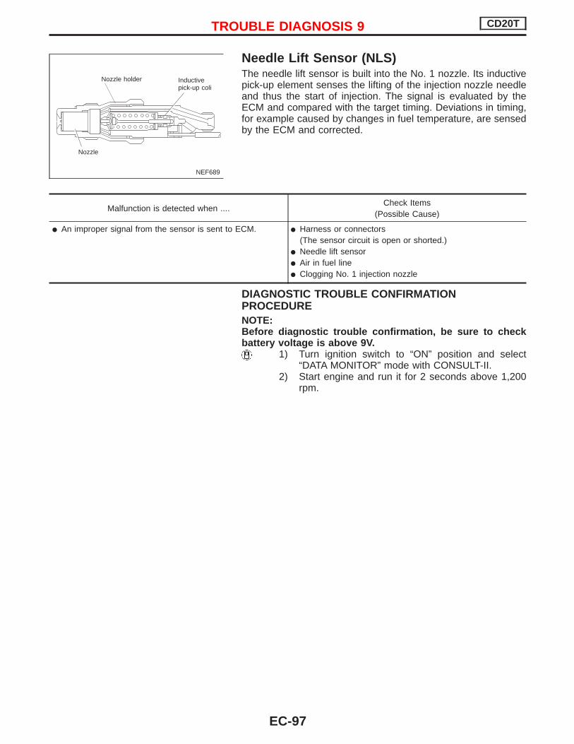
Needle Lift Sensor (NLS)The needle lift sensor is built into the No. 1 nozzle. Its inductivepick-up element senses the lifting of the injection nozzle needleand thus the start of injection. The signal is evaluated by theECM and compared with the target timing. Deviations in timing,for example caused by changes in fuel temperature, are sensedby the ECM and corrected.
Malfunction is detected when ....Check Items
(Possible Cause)
An improper signal from the sensor is sent to ECM. Harness or connectors(The sensor circuit is open or shorted.)
Needle lift sensor Air in fuel line Clogging No. 1 injection nozzle
DIAGNOSTIC TROUBLE CONFIRMATIONPROCEDURENOTE:Before diagnostic trouble confirmation, be sure to checkbattery voltage is above 9V.
1) Turn ignition switch to “ON” position and select“DATA MONITOR” mode with CONSULT-II.
2) Start engine and run it for 2 seconds above 1,200rpm.
NEF689
Nozzle holder
Nozzle
Inductivepick-up coli
TROUBLE DIAGNOSIS 9 CD20T
EC-97

YEC806
NEEDLELIFT SEN-SOR
: Detectable line for DTC: Non-detectable line for DTC
ECM
TROUBLE DIAGNOSIS 9 CD20T
Needle Lift Sensor (NLS) (Cont’d)
EC-98

DIAGNOSTIC PROCEDURE
INSPECTION START
CHECK FOR AIR IN FUEL FILTER.1. Move priming pump up and down to
purge air from fuel filter.2. Perform “DIAGNOSTIC TROUBLE
CODE CONFIRMATION PROCE-DURE”.
CHECK INPUT SIGNAL CIRCUIT.1. Turn ignition switch to “LOCK” posi-
tion.2. Disconnect ECM harness connector
and needle lift sensor harness con-nector.
3. Check harness continuity betweenneedle lift sensor connector terminalp1 and ECM connector terminal
345 .Continuity should exist.If OK, check harness for short-cir-cuit.
OK
ENG Repair harness or con-
nectors.
CHECK GROUND CIRCUIT.Check resistance between needle liftsensor connector terminal p2 andECM connector terminal 333 .Continuity should exist.If OK, check harness for short-circuit.
OK
ENG Repair harness or con-
nectors.
CHECK NO. 1 INJECTION NOZZLEFOR CLOGGING.Refer to spray pattern test of “INJEC-TION NOZZLE”.If NG, replace No. 1 injection nozzle.
Disconnect and reconnect harnessconnectors in the circuit. Then retest.
Trouble is not fixed
Check ECM pin terminals for damageand check the connection of ECM har-ness connector. Reconnect ECM har-ness connector and retest.
INSPECTION END
SEF671S
Priming pump
SEF606S
Needle lift sensorharness connector
NEF206A
Needle lift sensorconnector
NEF205A
Needle lift sensorconnector
H
H
H
H
H
H
H
TROUBLE DIAGNOSIS 9 CD20T
Needle Lift Sensor (NLS) (Cont’d)
EC-99
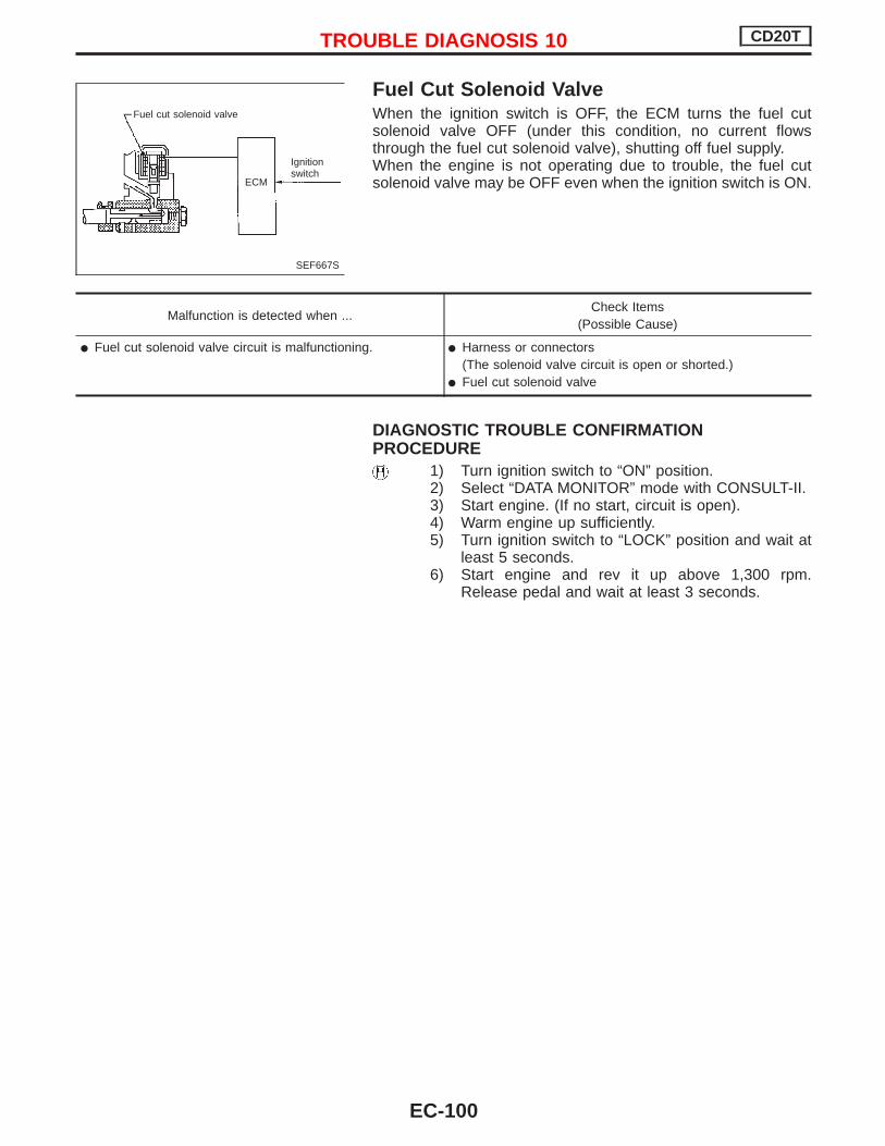
Fuel Cut Solenoid ValveWhen the ignition switch is OFF, the ECM turns the fuel cutsolenoid valve OFF (under this condition, no current flowsthrough the fuel cut solenoid valve), shutting off fuel supply.When the engine is not operating due to trouble, the fuel cutsolenoid valve may be OFF even when the ignition switch is ON.
Malfunction is detected when ...Check Items
(Possible Cause)
Fuel cut solenoid valve circuit is malfunctioning. Harness or connectors(The solenoid valve circuit is open or shorted.)
Fuel cut solenoid valve
DIAGNOSTIC TROUBLE CONFIRMATIONPROCEDURE
1) Turn ignition switch to “ON” position.2) Select “DATA MONITOR” mode with CONSULT-II.3) Start engine. (If no start, circuit is open).4) Warm engine up sufficiently.5) Turn ignition switch to “LOCK” position and wait at
least 5 seconds.6) Start engine and rev it up above 1,300 rpm.
Release pedal and wait at least 3 seconds.
SEF667S
Fuel cut solenoid valve
ECM
Ignitionswitch
TROUBLE DIAGNOSIS 10 CD20T
EC-100

YEC807
BATTERY
Refer to EL-POWER.
: Detectable line for DTC: Non-detectable line for DTC
INJECTION PUMP(FUEL CUT SOLE-NOID VALVE)
ENGINECONTROLMODULERELAY
ECM
TROUBLE DIAGNOSIS 10 CD20T
Fuel Cut Solenoid Valve (Cont’d)
EC-101

DIAGNOSTIC PROCEDURE
INSPECTION START
CHECK MAIN POWER SUPPLY.Check power supply. Refer toEC-CD-59.
CHECK OUTPUT SIGNAL CIRCUIT.1. Turn ignition switch to “ON”
position.2. Select “FUEL CUT SOL/V” in
“ACTIVE TEST” mode withCONSULT-II.
3. Touch “ON” and “OFF” alter-nately.
4. Check that operating sound isemitted.
--------------------------------------------------------------------------------------------------------------------------------- OR ---------------------------------------------------------------------------------------------------------------------------------1. Turn ignition switch to “LOCK”
position.2. Disconnect ECM harness con-
nector and electronic injectionpump harness connector.
3. Check harness continuitybetween fuel cut solenoid valveconnector terminal p1 andECM connector terminal 349 .Continuity should exist.If OK, check harness for short.
OK
ENG Repair harness or con-
nectors.
CHECK COMPONENT(Fuel cut solenoid valve).Refer to “COMPONENT INSPECTION”on next page.
OK
ENG Replace fuel cut solenoid
valve.
Disconnect and reconnect harnessconnectors in the circuit. Then retest.
Trouble is not fixed.
Check ECM pin terminals for damageand check the connection of ECM har-ness connector. Reconnect ECM har-ness connector and retest.
INSPECTION END
NEF815
.Electronic injectionpump harness connector(Fuel cut solenoid valve)
C2FCS01
NEF226A
Electronic injectionpump harness con-nection
H
H
H
H
H
H
TROUBLE DIAGNOSIS 10 CD20T
Fuel Cut Solenoid Valve (Cont’d)
EC-102

COMPONENT INSPECTION
Fuel cut solenoid valve1. Remove fuel cut solenoid valve.2. Check for lifting shaft when applying 12V direct current to
terminals.If NG, replace fuel cut solenoid valve.
SEF859SShaft
FUSE
TROUBLE DIAGNOSIS 10 CD20T
Fuel Cut Solenoid Valve (Cont’d)
EC-103

Fuel Temperature Sensor (FTS)The fuel temperature sensor is used to detect the fuel tempera-ture in the injection pump. The sensor modifies a voltage signalfrom the ECM. The modified signal returns to the ECM as the fueltemperature input. The sensor uses a thermistor which is sensi-tive to the change in temperature. The electrical resistance of thethermistor decreases as temperature increases.The sensor is built into the inside electrical circuit of the injectionpump.
Malfunction is detected when ...Check Items
(Possible Cause)
An excessively high or low voltage from the sensor isdetected by ECM.
Harness or connectors(The sensor circuit is open or shorted.)
Fuel temperature sensor
DIAGNOSTIC TROUBLE CONFIRMATIONPROCEDURE
1) Turn ignition switch to “ON” position.2) Select “DATA MONITOR” mode with CONSULT-II.3) Wait at least 5 seconds.
TROUBLE DIAGNOSIS 11 CD20T
EC-104

YEC808
INJECTION PUMP(FUEL TEMPERATURESENSOR)
: Detectable line for DTC: Non-detectable line for DTC
ECM
TROUBLE DIAGNOSIS 11 CD20T
Fuel Temperature Sensor (FTS) (Cont’d)
EC-105

DIAGNOSTIC PROCEDURE
INSPECTION START
CHECK POWER SUPPLY.1. Turn ignition switch to “LOCK” posi-
tion.2. Disconnect fuel temperature sensor
harness connector.3. Turn ignition switch to “ON” position.4. Check voltage between injection
pump connector terminal p6 andground with CONSULT-II or voltagetester.Voltage:
Approximately 5V
OK
ENG Repair harness or con-
nectors.
CHECK GROUND CIRCUIT.1. Turn ignition switch to “LOCK” posi-
tion.2. Check harness continuity between
injection pump connector terminal
p5 and ECM connector terminals335 , 436 .
Continuity should exist.If OK, check harness for short-cir-cuit.
OK
ENG Repair harness or con-
nectors.
CHECK COMPONENT(Fuel temperature sensor).Refer to “COMPONENT INSPECTION”on next page.
OK
ENG Have the injection pump
assembly serviced by anauthorised service repre-sentative.
Disconnect and reconnect harnessconnectors in the circuits. Then retest.
Trouble is not fixed.
Check ECM pin terminals for damageand check the connection of ECM har-ness connector. Reconnect ECM har-ness connector and retest.
INSPECTION END
NEF818
.Electronic injectionpump harness connector(Fuel temperature sensor)
NEF819
Injection pumpconnector
NEF208A
Injection pumpconnector
F50
H
H
H
H
H
H
TROUBLE DIAGNOSIS 11 CD20T
Fuel Temperature Sensor (FTS) (Cont’d)
EC-106

COMPONENT INSPECTION
Fuel temperature sensorWait until fuel temperature sensor reaches room temperature.Check resistance between terminals p5 and p6 .
Fuel temperature °C (°F) Resistance kΩ
25 (77) Approximately 1.9
If NG, have the injection pump assembly serviced by an autho-rised service representative.YEC366
TROUBLE DIAGNOSIS 11 CD20T
Fuel Temperature Sensor (FTS) (Cont’d)
EC-107

Accelerator Position Sensor & SwitchThe accelerator position sensor is installed on the upper end ofthe accelerator pedal assembly. The sensor detects the accel-erator position and sends a signal to the ECM. The ECM usesthe signal to determine the amount of fuel to be injected.
Malfunction is detected when ...Check Items
(Possible Cause)
An excessively low or high voltage from the sensor isdetected by the ECM.
Harness or connectors(The sensor or switch circuit is open or shorted.)
Accelerator position sensor Accelerator position switch
DIAGNOSTIC TROUBLE CONFIRMATIONPROCEDURE
1) Turn ignition switch to “ON” position.2) Select “DATA MONITOR” mode with CONSULT-II.3) Depress accelerator pedal fully and keep it for at least
1 second. Then release it and wait at least 5 seconds.
DIAGNOSTIC TROUBLE CONFIRMATIONPROCEDURE (For accelerator stiching)
1) Turn ignition switch to “ON” position.2) Select “DATA MONITOR” mode with CONSULT-II.3) Start engine and rev it up above 1,300 rpm.4) Depress brake pedal immediately after releasing
accelerator pedal and keep it at least 5 seconds.
NEF822
Out
put
volta
gebe
twee
nte
rmin
alN
o.4
and
5(V
)
Throttle valve opening angle (deg)
TROUBLE DIAGNOSIS 12 CD20T
EC-108

YEC809
ACCELERATORPOSITION SEN-SOR
: Detectable line for DTC: Non-detectable line for DTC
ECM
TROUBLE DIAGNOSIS 12 CD20T
Accelerator Position Sensor & Switch(Cont’d)
EC-109

YEC810
: Detectable line for DTC: Non-detectable line for DTC
ACCELERATORWORK UNIT
ECM
RELEASED
DEPRESSED
TROUBLE DIAGNOSIS 12 CD20T
Accelerator Position Sensor & Switch(Cont’d)
EC-110

DIAGNOSTIC PROCEDURE
INSPECTION START(Accelerator position sensor)
CHECK POWER SUPPLY.1. Turn ignition switch to “LOCK” position.2. Disconnect accelerator position sensor
harness connector.3. Turn ignition switch to “ON” position.4. Check voltage between accelerator posi-
tion sensor connector terminal p5 andground with CONSULT-II or voltagetester.Voltage: Approximately 5V
OK
ENG Check the following:
Harness connectorsM50 , F104
Harness for open orshort-circuit betweenECM and acceleratorposition sensor.
If NG, repair harness orconnectors.
CHECK GROUND CIRCUIT.1. Turn ignition switch to “LOCK” position.2. Check harness continuity between accel-
erator position sensor connector terminal
p4 and engine ground.Continuity should exist.If OK, check harness for short-circuit.
OK
ENG Check the following:
Harness connectorsM50 , F104
Harness for open orshort-circuit betweenECM and acceleratorposition sensor.
If NG, repair harness orconnectors.
CHECK INPUT SIGNAL CIRCUIT.1. Disconnect ECM harness connector.2. Check harness continuity between ECM
terminal 434 and accelerator positionsensor connector terminal p2 .Continuity should exist.If OK, check harness for short-circuit.
OK
ENG Check the following
Harness connectorsM50 , F104
Harness for open orshort-circuit betweenECM and acceleratorposition sensor
If NG, repair harness orconnectors.
CHECK COMPONENT(Accelerator position sensor).Refer to “COMPONENT INSPECTION”EC-CD-113.
OK
ENG Replace accelerator pedal
assembly.
Disconnect and reconnect harness connec-tors in the circuit. Then retest.
Trouble is not fixed.
Check ECM pin terminals for damage andcheck the connection of ECM harness con-nector. Reconnect ECM harness connectorand retest.
INSPECTION END
NEF823
Accelerator positionsensor harness con-nector
Acceleratorpedal
NEF824
Accelerator positionsensor connector
NEF825
Accelerator positionsensor connector
NEF209A
Accelerator positionsensor connector
H
H
H
H
H
H
H
TROUBLE DIAGNOSIS 12 CD20T
Accelerator Position Sensor & Switch(Cont’d)
EC-111

DIAGNOSTIC PROCEDURE
INSPECTION START(Accelerator position switch)
CHECK OVERALL FUNCTION.1. Turn ignition switch to “ON”
position.2. Check “OFF ACCEL POS” in
“DATA MONITOR” mode withCONSULT-II.Accelerator pedal released:
ONAccelerator pedal depressed:
OFF------------------------------------------------------------------------------------------------------------------------------- OR -------------------------------------------------------------------------------------------------------------------------------
1. Turn ignition switch to “LOCK”position.
2. Check continuity between ECMconnector terminal 435 andground.Continuity:
Accelerator pedal released:No
Accelerator pedal depressed:Yes
NG
EOK
INSPECTION END
CHECK GROUND CIRCUIT.1. Disconnect accelerator switch harness
connector.2. Check harness continuity between
accelerator switch connector terminalp1 and ECM connector terminal 426 .Continuity should exist.
OK
ENG
Check the following: Harness connectors
M52 , F103 Harness for open circuit
between accelerator switchand ECM connector termi-nal 426 .
If NG, repair harness or con-nectors.
CHECK INPUT SIGNAL CIRCUIT.Check harness continuity between ECMconnector terminal 435 and acceleratorswitch connector terminal p3 .Continuity should exist.
OK
ENG
Check the following: Harness connectors
F103 , M52 Harness for open or short-
circuit between acceleratorswitch and ECM
CHECK COMPONENT(Accelerator switch).Refer to “COMPONENT INSPECTION”on next page.
OK
ENG
Replace accelerator switch.
Disconnect and reconnect harness connec-tors in the circuit. Then retest.
Trouble is not fixed
Check ECM pin terminals for damage andcheck the connection of ECM harness con-nector. Reconnect ECM harness connectorand retest.
INSPECTION END
PEF123W
NEF210A
NEF212A
Acceleratorswitch con-nector
NEF211A
Acceleratorswitch connector
H
H
H
H
H
H
H
TROUBLE DIAGNOSIS 12 CD20T
Accelerator Position Sensor & Switch(Cont’d)
EC-112

COMPONENT INSPECTION
Accelerator position sensor1. Disconnect accelerator position sensor harness connector.2. Make sure that resistance between accelerator position sen-
sor terminals p2 and p4 changes when opening throttlevalve manually.
Throttle valve conditions Resistance [at 25°C (77°F)]
Completely closed Approximately 1.2 kΩ
Partially open 1.2 - 1.9 kΩ
Completely open Approximately 1.9 kΩ
If NG, replace accelerator pedal assembly.
CAUTION: Do not disassemble accelerator pedal assembly.
COMPONENT INSPECTION
Accelerator switch1. Disconnect accelerator switch harness connector.2. Check continuity between accelerator switch connector ter-
minals p1 and p3 .
Conditions Continuity
Accelerator pedal released No
Accelerator pedal depressed Yes
If NG, replace accelerator pedal assembly.
CAUTION: Do not disassemble accelerator pedal assembly.
1 2 543 M68
2 4
YEC368
Accelerator positionsensor connector
M68
1 2 543 M68
1 3
YEC369
Accelerator positionsensor connector
M68
TROUBLE DIAGNOSIS 12 CD20T
Accelerator Position Sensor & Switch(Cont’d)
EC-113

Crankshaft Position Sensor (TDC)The crankshaft position sensor (TDC) monitors engine speed bymeans of signals from the sensing plate (with two protrusions)installed to the crankshaft pulley. The datum signal output isdetected at ATDC 70° and sent to the ECM. The sensor signalis used for fuel injection control and fuel injection timing control.
Malfunction is detected when ....Check Items
(Possible Cause)
An incorrect signal from the sensor is detected by ECMduring engine running and cranking.
Harness or connectors(The sensor circuit is open.)
Crankshaft position sensor (TDC)
DIAGNOSTIC TROUBLE CONFIRMATIONPROCEDURE
Before performing the following procedure, confirmthat battery voltage is more than 9V.
1) Turn ignition switch to “ON” position and select“DATA MONITOR” mode with CONSULT-II.
2) Start engine and run it for at least 3 seconds above1,200 rpm.
SEF615S
Core
Magnet
Coil
SEF616S
Crank pulley
Crankshaft positionsensor (TDC)
TROUBLE DIAGNOSIS 13 CD20E
EC-114

YEC811
CRANKSHAFT POSI-TION SENSOR (TDC)
: Detectable line for DTC: Non-detectable line for DTC
ECM
TROUBLE DIAGNOSIS 13 CD20E
Crankshaft Position Sensor (TDC) (Cont’d)
EC-115

DIAGNOSTIC PROCEDURE
INSPECTION START
CHECK INPUT SIGNAL CIRCUIT.1. Turn ignition switch to “LOCK” posi-
tion.2. Disconnect crankshaft position sen-
sor (TDC) and ECM harness con-nectors.
3. Check continuity between ECM ter-minal 344 and crankshaft positionsensor (TDC) connector terminal
p3 .Continuity should exist.If OK, check harness for short-cir-cuit.
OK
ENG Repair harness or con-
nectors.
Loosen and retighten engine groundscrews.
OK
CHECK GROUND CIRCUIT.Check harness continuity betweencrankshaft position sensor (TDC) con-nector terminal p2 and ECM connec-tor terminal 331 .Continuity should exist.If OK, check harness for short-circuit.
OK
ENG Repair harness or con-
nectors.
CHECK COMPONENT[Crankshaft position sensor (TDC)].Refer to “COMPONENT INSPECTION”on next page.
OK
ENG Replace crankshaft posi-
tion sensor (TDC).
Disconnect and reconnect harnessconnectors in the circuit. Then retest.
Trouble is not fixed
Check ECM pin terminals for damageand check the connection of ECM har-ness connector. Reconnect ECM har-ness connector and retest.
INSPECTION END
SEF617S
Crankshaft positionsensor (TDC)harness connector
NEF213A
Crankshaft positionharness connector
NEF214A
Crankshaft positionsensor connector
H
H
H
H
H
H
H
TROUBLE DIAGNOSIS 13 CD20E
Crankshaft Position Sensor (TDC) (Cont’d)
EC-116
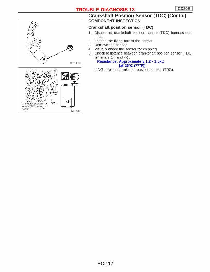
COMPONENT INSPECTION
Crankshaft position sensor (TDC)1. Disconnect crankshaft position sensor (TDC) harness con-
nector.2. Loosen the fixing bolt of the sensor.3. Remove the sensor.4. Visually check the sensor for chipping.5. Check resistance between crankshaft position sensor (TDC)
terminals p2 and p3 .Resistance: Approximately 1.2 - 1.5k Ω
[at 25°C (77°F)]If NG, replace crankshaft position sensor (TDC).
SEF620S
NEF440
Crankshaft positionsensor (TDC) con-nector
TROUBLE DIAGNOSIS 13 CD20E
Crankshaft Position Sensor (TDC) (Cont’d)
EC-117

Glow Control SystemWhen coolant temperature is lower than 75°C (167°F): Ignition switch ON
After ignition switch has been turned to ON, the glow relayturns ON for a period of time depending on engine coolanttemperature, allowing current to flow through the glow plugs.
StartingAfter starting the engine, current will flow through the glowplugs for 300 seconds, or until the coolant temperatureexceeds 50°C (122°F).
COMPONENT DESCRIPTION
Glow plugThe glow plug is provided with a ceramic heating element toobtain a high-temperature resistance. It glows in response to asignal sent from the ECM, allowing current to flow through theglow plug via the glow relay.
Malfunction is detected when ....Check Items
(Possible cause)
Glow relay signal circuit is open or shorted. Harness or connectors(The glow relay signal circuit is open or shorted)
Glow relay
Glow indicator lamp circuit is open or shorted. Harness or connectors(The glow indicator lamp circuit is open or shorted.)
Glow lamp
Glow lamp indicator
Tim
e,
[S]
.
Engine coolant temperature
Pre-glow
Tim
e,
[S]
Engine coolant temperature.
Post glow
. Tim
e,
[S]
Engine coolant temperature
.1.5
.(-40) (-4) (32) (68) (104) (140)
.(-40) (-4) (32) (68) (104) (140)
.(-40) (-4) (32) (68) (104) (140)
, °C (°F)
., °C (°F)
., °C (°F)
NEF834
.
.
SEF857S
Ceramic heaterResistor
TROUBLE DIAGNOSES 14 CD20T
EC-118

DIAGNOSTIC TROUBLE CONFIRMATIONPROCEDURE
1) Turn ignition switch to “ON” position.2) Select “DATA MONITOR” mode with CONSULT-II.3) Wait at least 5 seconds.
TROUBLE DIAGNOSES 14 CD20T
Glow Control System (Cont’d)
EC-119
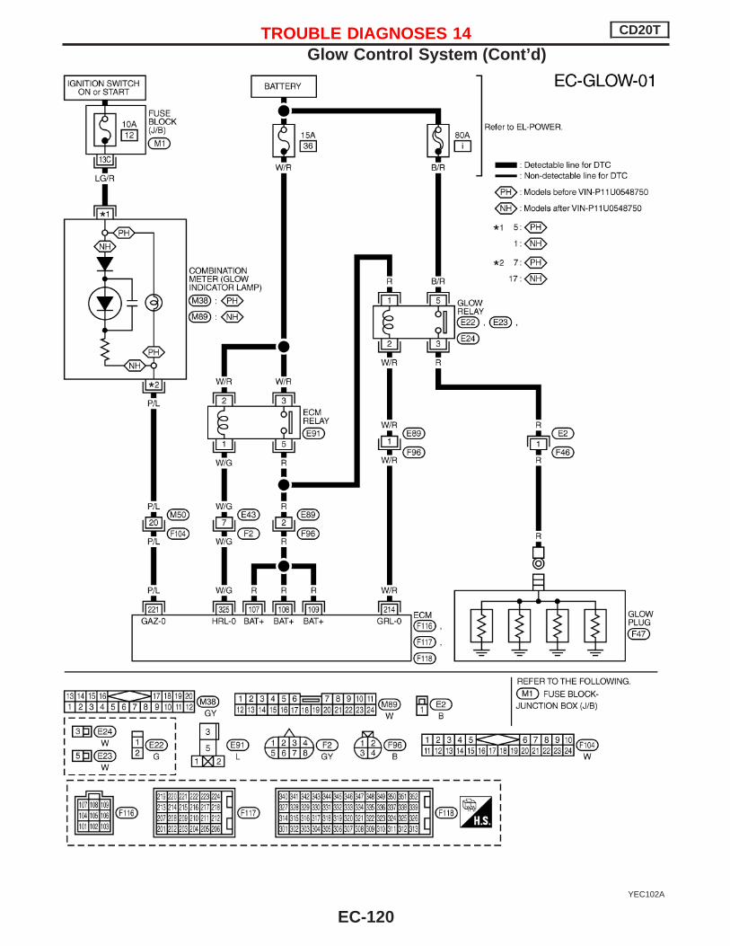
YEC102A
TROUBLE DIAGNOSES 14 CD20T
Glow Control System (Cont’d)
EC-120

DIAGNOSTIC PROCEDURE
INSPECTION START(Glow relay signal circuit)
CHECK MAIN POWER SUPPLY.Check power supply to ECCS-D relay.Refer to “TROUBLE DIAGNOSIS FORPOWER SUPPLY” (EC-CD-59).
CHECK POWER SUPPLY.1. Turn ignition switch to the “LOCK”
position.2. Disconnect glow relay.3. Turn ignition switch to the “ON” posi-
tion.4. Check voltage between glow relay
connector terminals p1 , p5 andground with tester.Voltage: Battery voltage
OK
ENG Check the following:
15A fuse 80A fusible link Harness continuity
between glow relayand fuse.
If NG, replace fuse orfusible link or repair har-ness or connectors.
CHECK OUTPUT SIGNAL CIRCUIT.1. Turn ignition switch to the “LOCK”
position.2. Disconnect ECM harness connector.3. Check harness continuity between
ECM connector terminal 214 andglow relay connector terminal p2 .Continuity should exist.If OK, check harness for short-cir-cuit.
OK
ENG Check harness connec-
tors F96 , E89
Repair harness or con-nectors.
CHECK GLOW PLUG AND GLOWRELAY.Refer to “COMPONENT INSPECTION”(EC-CD-124, 125).
OK
ENG Replace glow plug or
glow relay.
Disconnect and reconnect harnessconnectors in the circuit. Then retest.
Trouble is not fixed
Check ECM pin terminals for damageand check the connection of ECM har-ness connector. Reconnect ECM har-ness connector and retest.
INSPECTION END
NEF835
Glow relay
Glow relayharness connector
YEC370
Glow relay con-nector
NEF215A
Glow relayconnector
H
H
H
H
H
H
H
TROUBLE DIAGNOSES 14 CD20T
Glow Control System (Cont’d)
EC-121

INSPECTION START(Glow indicator lamp circuit)
CHECK POWER SUPPLY CIRCUIT.1. Turn ignition switch to “LOCK” posi-
tion.2. Disconnect combination meter har-
ness connector.3. Turn ignition switch to “ON” position.4. Check voltage between combination
meter harness connector terminalp5 or p1 and body ground.Voltage: Battery voltage
OK
ENG Check the following:
Harness for open orshort-circuit betweencombination meter andbattery.
10A fuseIf NG, replace fuse orrepair harness or con-nectors.
CHECK GROUND CIRCUIT.1. Turn ignition switch to “LOCK” posi-
tion.2. Disconnect ECM harness connector.3. Check harness continuity between
ECM connector terminal 221 andcombination meter connector termi-nal p7 or p17 .Continuity should exist.If OK, check harness for short-cir-cuit.
OK
ENG Check the following:
Harness connectorsM50 , F104
Harness for open orshort-circuit betweenECM and combinationmeter.
If NG, repair harness orconnectors.
CHECK GLOW INDICATOR LAMP.Make sure that glow indicator lamp isnot burnt out.
OK
ENG Replace glow indicator
lamp.
Disconnect and reconnect harnessconnectors in the circuit. Then retest.
Trouble is not fixed
Check ECM pin terminals for damageand check the connection of ECM har-ness connector. Reconnect ECM har-ness connector and retest.
INSPECTION END
YEC119A
YEC120A
H
H
H
H
H
H
TROUBLE DIAGNOSES 14 CD20T
Glow Control System (Cont’d)
EC-122

INSPECTION START(Glow plug circuit)
CHECK POWER SUPPLY-I.1. Turn ignition switch to “LOCK” posi-
tion.2. Disconnect glow relay harness con-
nector.3. Check voltage between glow relay
harness connector terminal p5 andengine ground.Voltage: Battery voltage
OK
ENG Check the following:
Harness for open orshort-circuit betweenglow relay and battery.
80A fusible linkIf NG, replace fusible linkand repair harness con-nectors.
CHECK POWER SUPPLY-II.1. Disconnect glow plug harness con-
nector.2. Check harness continuity between
glow plug harness connector andglow relay harness connector termi-nal p3 .Continuity should exist.If OK, check harness for short-cir-cuit.
OK
ENG Check the following:
Harness connectorsE2 , F46
Harness for open orshort-circuit betweenglow plug and glowrelay.
If NG, repair harness orconnector.
CHECK GLOW PLUG AND GLOWRELAY.Refer to “COMPONENT INSPECTION”(EC-CD-124, 125).
OK
ENG Replace glow plug or
glow relay.
Disconnect and reconnect harnessconnectors in the circuit. Then retest.
INSPECTION END
NEF873
Glow relay connector
YEC374
Glow relayconnector
Glow plugconnector
H
H
H
H
H
TROUBLE DIAGNOSES 14 CD20T
Glow Control System (Cont’d)
EC-123
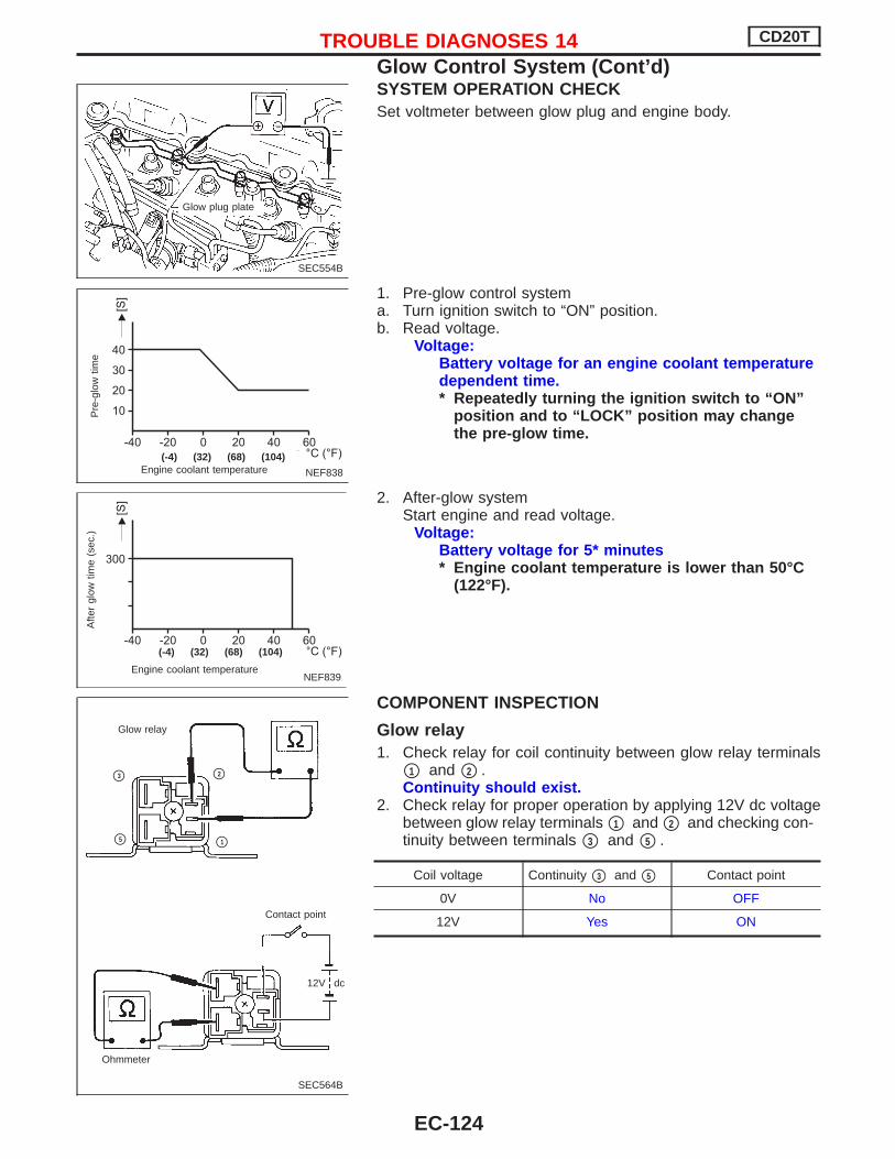
SYSTEM OPERATION CHECKSet voltmeter between glow plug and engine body.
1. Pre-glow control systema. Turn ignition switch to “ON” position.b. Read voltage.
Voltage:Battery voltage for an engine coolant temperaturedependent time.* Repeatedly turning the ignition switch to “ON”
position and to “LOCK” position may changethe pre-glow time.
2. After-glow systemStart engine and read voltage.
Voltage:Battery voltage for 5* minutes* Engine coolant temperature is lower than 50°C
(122°F).
COMPONENT INSPECTION
Glow relay1. Check relay for coil continuity between glow relay terminals
p1 and p2 .Continuity should exist.
2. Check relay for proper operation by applying 12V dc voltagebetween glow relay terminals p1 and p2 and checking con-tinuity between terminals p3 and p5 .
Coil voltage Continuity p3 and p5 Contact point
0V No OFF
12V Yes ON
SEC554B
Glow plug plate
NEF838
Pre
-glo
wtim
e
Engine coolant temperature
.(-4) (32) (68) (104)
NEF839Engine coolant temperature
Afte
rgl
owtim
e(s
ec.)
.(-4) (32) (68) (104)
SEC564B
Ohmmeter
Glow relay
Contact point
12V dc
p2
p1
p3
p5
TROUBLE DIAGNOSES 14 CD20T
Glow Control System (Cont’d)
EC-124

Glow plug1. Remove glow plug connecting plate.2. Check each glow plug for continuity.
Continuity should exist:Approximately 0.5 Ω [at 25°C (77°F)]
If NG, replace glow plug.
3. Install glow plug connecting plate securely. Do not bump glow plug heating element. If it is bumped,
replace glow plug with new one. (If glow plug is droppedfrom a height of 0.1 m (3.94 in) or greater, replace withnew one.)
If glow plug installation hole is contaminated withcarbon, remove using a reamer or suitable tool.
Hand-tighten glow plug by turning it 2 to 3 times, thentighten using a tool to specified torque.
: 15 - 20 N·m (1.5 - 2.0 kg-m, 11 - 14 ft-lb)
SEF630K
Ohmmeter
SEC565B
Glow nut
Glow harnessConnectingplate
Washer
Spring washer
Glow plug
TROUBLE DIAGNOSES 14 CD20T
Glow Control System (Cont’d)
EC-125

Air Conditioner Cut ControlThe Air Conditioner relay is controlled by the ECM. During thefollowing conditions, the ECM will cut the power supply towardsthe air conditioner relay: Starting engine Quick acceleration from low speed Undershooting of idle speed High engine coolant temperature [above 107°C (225°F)]. Malfunctioning of engine speed sensor, accelerator position
sensor or vehicle speed sensor when engine speed is below2,100 rpm.
Malfunction is detected when ....Check Items
(Possible cause)
Air conditioner relay signal circuit is shorted. Harness or connectors(The air conditioner relay signal circuit is shorted).
Air conditioner relay
DIAGNOSTIC TROUBLE CONFIRMATIONPROCEDURE
1) Turn ignition switch and air conditioner switch to the“ON” position.
2) Select “DATA MONITOR” mode with CONSULT-II.3) Wait at least 2 seconds.
TROUBLE DIAGNOSES 15 CD20T
EC-126

YEC813
IGNITION SWITCHON or START
FUSEBLOCK(J/B) Refer to EL-POWER.
: Detectable line for DTC: Non-detectable line for DTC
AIR CONDITIONERRELAY
To compressor(Refer to HA-A/C.)
A/CCONTROLPANEL
LOW HIGH
NORMAL
TRIPLE-PRESSURESWITCH
THERMISTOR
THERMOCONTROLAMP.
ECM
REFER TO THE FOLLOWING
FUSE BLOCK - Junction Box (J/B)
FUSE BLOCK - Junction Box (J/B)
TROUBLE DIAGNOSES 15 CD20T
Air Conditioner Cut Control (Cont’d)
EC-127

INSPECTION START(Air conditioner relay signal circuit)
CHECK POWER SUPPLY.1. Turn ignition switch to “LOCK” posi-
tion.2. Disconnect air conditioner relay har-
ness connector.3. Turn ignition switch to “ON” position.4. Check voltage between air condi-
tioner relay connector terminals p2 ,p5 and engine ground.Voltage: Battery voltage
OK
ENG Check the following:
Harness and connec-tors for open or short-circuit between ignitionswitch and air condi-tioner relay.
10A fuseIf NG, replace or repairthe parts affected.
CHECK GROUND CIRCUIT.1. Turn ignition switch to “LOCK” posi-
tion.2. Disconnect ECM harness connector.3. Check harness continuity between
ECM harness connector terminal204 and air conditioner relay har-
ness connector terminal p1 .Continuity should exist.If OK, check harness for short-cir-cuit.
OK
ENG Check the following:
Harness connectorsE43 , F2
Harness for open orshort-circuit betweenECM and air condi-tioner relay.
If NG, repair harness orconnectors.
CHECK AIR CONDITIONER RELAY.Refer to HA section for inspection.
OK
ENG Replace air conditioner
relay.
Disconnect and reconnect harnessconnectors in the circuit. Then retest.
Trouble is not fixed
Check ECM pin terminals for damageand check the connection of ECM har-ness connector. Reconnect ECM har-ness connector and retest.
INSPECTION END
YEC375
Air conditioner relayharness connector
Air conditioner relayharness connector
NEF218A
H
H
H
H
H
H
TROUBLE DIAGNOSES 15 CD20T
Air Conditioner Cut Control (Cont’d)
EC-128

EGRC-Solenoid ValveSYSTEM DESCRIPTION
Camshaft position sensor (TDC) EEngine speed
ECM
Air conditioner switch EAir conditioner “ON” signal
E EGRC-solenoid valve
Engine coolant temperature sensor EEngine coolant temperature
Atmospheric pressure sensor EAtmospheric pressure
Mass air flow sensor EMass air flow
The ECM receives signals sent from the engine coolant tempera-ture sensor, crankshaft position sensor (TDC), atmospheric pres-sure sensor, mass air flow sensor and air conditioner switch todetermine engine speed and operating conditions. Based onthese signals, the ECM controls the EGR control solenoid valveoperation.No EGR operation will take place when the engine coolant tem-perature is below 70°C (158°F), when idling, at starting and dur-ing a period of time after starting the engine (70 - 200 seconds,depending on engine coolant temperature).
Engine coolanttemperature °C (°F) Load EGRC-solenoid valve EGR valve Amount of EGR gas
Below 70 (158) Any OFF(Closed) Fully closed —
Above 70 (158)Low load ON
(Open) Fully open Large
High load OFF(Closed) Fully closed —
COMPONENT DESCRIPTIONThe EGR control solenoid valves control vacuum pressure act-ing on the EGR valve. The EGR control valve will then be fullyopened or fully closed, as required.Thus, intake air passages are opened or closed in relation toexhaust gas and intake air. Utilizing the relationship betweenexhaust gas pressure and intake air pressure control, the amountof EGR (exhaust gas recirculated) is regulated in large or smallvolumes.
Malfunction is detected when ....Check Items
(Possible cause)
EGRC-solenoid valve A circuit is shorted. Harness or connectors(EGRC-solenoid valve A circuit is open or shorted).
EGRC solenoid valve A
SEF240PH
To control valve
To intakeair flow
Vacuumsignal
TROUBLE DIAGNOSES 16 CD20T
EC-129

DIAGNOSTIC TROUBLE CONFIRMATIONPROCEDURE
1) Turn ignition switch to the “ON” position.2) Select “DATA MONITOR” mode with CONSULT-II.3) Wait at least 2 seconds.
TROUBLE DIAGNOSES 16 CD20T
EGRC-Solenoid Valve (Cont’d)
EC-130

YEC814
BATTERY
Refer to EL-POWER. : Detectable line for DTC
: Non-detectable line for DTC
EGRC-SOLENOIDVALVE A
ENGINECONTROLMODULERELAY
ECM
EGRC-SOLENOIDVALVE B
TROUBLE DIAGNOSES 16 CD20T
EGRC-Solenoid Valve (Cont’d)
EC-131

DIAGNOSTIC PROCEDURE
INSPECTION START(Circuit for EGRC-solenoid valve A)
CHECK MAIN POWER SUPPLY.Refer to Trouble Diagnosis for mainpower supply (EC-CD-59)
CHECK POWER SUPPLY.1. Turn ignition switch to the “LOCK”
position.2. Disconnect EGRC-solenoid valve A
harness connector.3. Turn ignition switch to the “ON” posi-
tion.4. Check voltage between connector
terminal p2 and engine ground.Voltage: Battery voltage
OK
ENG Check the following:
Harness continuitybetween ECM relayand EGRC-solenoidvalve A connector.
If NG, repair harness orconnectors.
CHECK OUTPUT SIGNAL CIRCUIT.1. Turn ignition switch to the “LOCK”
position.2. Disconnect ECM harness connector.3. Check harness continuity between
ECM harness connector terminal208 and EGRC solenoid valve A
connector terminal p1 .Continuity should exist.If OK, check harness for short-cir-cuit.
OK
ENG Check the following:
Harness for open orshort-circuit betweenECM and solenoidvalve.
If NG, repair harness orconnectors.
CHECK COMPONENTS(EGRC-solenoid valve).Refer to “COMPONENT INSPECTION”EC-CD-135.
OK
ENG Replace malfunctioning
component(s).
Disconnect and reconnect harnessconnectors in the circuit. Then retest.
Trouble is not fixed
Check ECM pin terminals for damageor the connection of ECM harness con-nector. Reconnect ECM harness con-nector and retest.
INSPECTION END
EGRC solenoid valve Aharness connector
NEF219A
EGRC solenoidvalve A harnessconnector
NEF220A
H
H
H
H
H
H
H
TROUBLE DIAGNOSES 16 CD20T
EGRC-Solenoid Valve (Cont’d)
EC-132
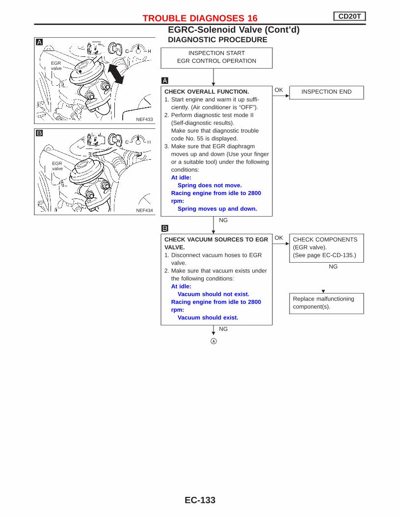
DIAGNOSTIC PROCEDURE
INSPECTION STARTEGR CONTROL OPERATION
CHECK OVERALL FUNCTION.1. Start engine and warm it up suffi-
ciently. (Air conditioner is “OFF”).2. Perform diagnostic test mode II
(Self-diagnostic results).Make sure that diagnostic troublecode No. 55 is displayed.
3. Make sure that EGR diaphragmmoves up and down (Use your fingeror a suitable tool) under the followingconditions:At idle:
Spring does not move.Racing engine from idle to 2800rpm:
Spring moves up and down.
NG
EOK INSPECTION END
CHECK VACUUM SOURCES TO EGRVALVE.1. Disconnect vacuum hoses to EGR
valve.2. Make sure that vacuum exists under
the following conditions:At idle:
Vacuum should not exist.Racing engine from idle to 2800rpm:
Vacuum should exist.
NG
EOK CHECK COMPONENTS
(EGR valve).(See page EC-CD-135.)
NG
Replace malfunctioningcomponent(s).
pA
NEF433
EGRvalve
NEF434
EGRvalve
H
H
H
H
TROUBLE DIAGNOSES 16 CD20T
EGRC-Solenoid Valve (Cont’d)
EC-133

pA
CHECK CONTROL FUNCTION.1. Turn ignition switch to “ON”
position.2. Turn EGRC-solenoid valve A
“ON” and “OFF” in “ACTIVETEST” mode with CONSULT-IIand check operating sound.
---------------------------------------------------------------------------------------------------------------------------------------- OR ----------------------------------------------------------------------------------------------------------------------------------------1. Check voltage between EGRC
solenoid valve A connector ter-minal p1 , and ground withtester under the following condi-tions:Voltage:
At idleBattery voltage
Engine speed is 2,800 rpmApproximately 0.4V
NG
EOK CHECK VACUUM
HOSE.Check vacuum hosefor clogging, cracks orimproper connection.
Perform electrical circuit inspection.Refer to EC-CD-132.
OK
pB
C2ESA01
NEF435
NEF846
Crack
Clogging
Improper connection
.
NEF436
.EGRC-solenoid valveharness connector
H
H
H
TROUBLE DIAGNOSES 16 CD20T
EGRC-Solenoid Valve (Cont’d)
EC-134

COMPONENT INSPECTION
EGR valveApply vacuum to EGR vacuum port with a hand vacuum pump.EGR valve spring should lift.If NG, replace EGR valve.
EGRC-solenoid valveCheck air passage continuity.
ConditionAir passagecontinuity
between pA and pB
Air passagecontinuity
between pA and pC
12V direct current sup-ply between terminals
p1 and p2
Yes No
No supply No Yes
If NG, replace solenoid valve.
MEF137D
EGR valve
MEC488B
BATTERY
FUSE
TROUBLE DIAGNOSES 16 CD20T
EGRC-Solenoid Valve (Cont’d)
EC-135

Brake SwitchThe ECM receives signals from two brake switches. One is aconventional brake lamp switch, the other is referred to as aredundant (RDNT) brake switch.In case the accelerator pedal does not return to the idle position(pedal sticks), the driver will react by depressing the brake. Inthis (emergency) situation, the ECM will disregard the accelera-tor pedal signal and bring back the engine speed to 1200 rpm.
Malfunction is detected when ...Check Items
(Possible Cause)
Brake switch circuits are open or shorted. Harness or connectors(Brake switch circuits are open or shorted.)
Stop lamp switch RDNT brake switch
DIAGNOSTIC TROUBLE CONFIRMATIONPROCEDURE
1) Turn ignition switch to “ON” position and select “DATAMONITOR” mode with CONSULT-II.
2) Depress brake pedal for at least 1 minute.
TROUBLE DIAGNOSES 17 CD20T
EC-136

YEC103A
TROUBLE DIAGNOSES 17 CD20T
Brake Switch (Cont’d)
EC-137

INSPECTION START(RDNT brake switch)
CHECK POWER SUPPLY.1. Turn ignition switch to “LOCK” posi-
tion.2. Disconnect RDNT brake switch har-
ness connector.3. Turn ignition switch to “ON” position.4. Check voltage between RDNT brake
switch harness connector terminal
p1 and body ground.Voltage: Battery voltage
OK
ENG Check the following:
Harness connectorsF104 , M50
(RHD models) Harness connectors
F2 , E43
(LHD models) Harness for open or
short-circuit betweenRDNT brake switchharness connector ter-minal p1 and ECMconnector terminal
416 .If NG, repair harness orconnectors.
CHECK GROUND CIRCUIT.1. Turn ignition switch to “LOCK” posi-
tion.2. Check harness continuity between
RDNT brake switch harness connec-tor terminal p2 and body ground.Continuity should exist.If OK, check harness for short-circuit.
OK
ENG Repair harness or con-
nectors.
CHECK COMPONENT.(RDNT brake switch)Refer to “COMPONENT INSPECTION”on next page.
OK
Disconnect and reconnect harnessconnectors in the circuit. Then retest.
Trouble is not fixed
Check ECM pin terminals for damageand check the connection of ECM har-ness connector. Reconnect ECM har-ness connector and retest.
INSPECTION END
YEC377
RDNT brake switchharness connector
YEC378
RDNT brake switchharness connector
H
H
H
H
H
H
TROUBLE DIAGNOSES 17 CD20T
Brake Switch (Cont’d)
EC-138

COMPONENT INSPECTION
Stop lamp switch and RDNT brake switch1. Turn ignition switch to “LOCK” position.2. Disconnect switch harness connectors.3. Check continuity between terminals p1 and p2 .Continuity:
Brake pedal Stop lamp switch RDNT brake switch
Released No No
Depressed Yes Yes
If NG, replace stop lamp switch or RDNT brake switch.
1 2
12
YEC379
TROUBLE DIAGNOSES 17 CD20T
Brake Switch (Cont’d)
EC-139

ECM RelayThe ECM Relay shuts off the main power supply to the ECMwithin 5 seconds after the ignition switch has turned to the“LOCK” position.
Malfunction is detected when ....Check Items
(Possible cause)
ECM relay shut-off time is too late. Harness or connectors(The ECM relay circuit is shorted).
ECM relay ECM
DIAGNOSTIC TROUBLE CONFIRMATIONPROCEDURE
1) Turn ignition switch to the “ON” position and select“DATA MONITOR” mode with CONSULT-II.
2) Turn ignition switch to the “LOCK” position and waitat least 5 seconds.
3) Turn ignition switch to the “ON” position and wait atleast 2 seconds.
DIAGNOSTIC PROCEDURERefer to “Trouble Diagnosis for Power Supply” (EC-CD-59) forECM relay circuit inspection.
TROUBLE DIAGNOSES 18 CD20T
EC-140

MI & Data Link ConnectorsMalfunction indicator (MI) circuit is monitored for open or short-circuit. If the circuit is malfunctioning, MI can not report it butCONSULT-II can.
Malfunction is detected when ....Check Items
(Possible cause)
MI circuit is open or shorted. Harness or connectors(MI circuit is open or shorted).
MI lamp ECM
DIAGNOSTIC TROUBLE CONFIRMATIONPROCEDURE
1) Turn ignition switch to “ON” position and select “DATAMONITOR” mode with CONSULT-II.
2) Start engine and run it for at least 2 seconds at idlespeed.
-------------------------------------------------------------------------------------------------------------------------------------------------------------------------------------------------------------------------------------------------------------- OR --------------------------------------------------------------------------------------------------------------------------------------------------------------------------------------------------------------------------------------------------------------OVERALL FUNCTION CHECK1) Turn ignition switch to “ON” position.2) Check that MI lits on.
TROUBLE DIAGNOSES 19 CD20T
EC-141

YEC104A
TROUBLE DIAGNOSES 19 CD20T
MI & Data Link Connectors (Cont’d)
EC-142

DIAGNOSTIC PROCEDURE: MODELS BEFORE VIN -P11U0548750
INSPECTION START(MI circuit)
CHECK MI BULB.1. Turn ignition switch to “LOCK” posi-
tion.2. Disconnect combination meter har-
ness connector.3. Apply battery voltage between com-
bination meter terminal p5 and p13 .4. Check that MI lits on.
OK
ENG Replace MI bulb.
CHECK POWER SUPPLY.1. Turn ignition switch to “ON” position.2. Check voltage between combination
meter terminal p5 and bodyground.Voltage: Battery voltage
OK
ENG Check the following:
Harness for open orshort-circuit betweencombination meter andignition switch.
10A fuseIf NG, repair or replaceharness or fuse.
CHECK GROUND CIRCUIT.1. Turn ignition switch to “LOCK” posi-
tion.2. Disconnect ECM harness connector.3. Check continuity between combina-
tion meter connector terminal p13
and ECM connector terminal 215 .Continuity should exist.If OK, check harness for short-cir-cuit.
OK
ENG Check the following:
Harness connectorsM50 , F104
If NG, repair harness orconnectors. Harness and connec-
tors for open or short-circuit between ECMand combination meter.
Disconnect and reconnect harnessconnectors in the circuit. Then retest.
Trouble is not fixed
Check ECM pin terminals for damageand check the connection of ECM har-ness connector. Reconnect ECM har-ness connector and retest.
INSPECTION END
YEC380
Combination meterharness connector
YEC381
Combination meterharness connector
NEF222A
Combination meterharness connector
H
H
H
H
H
H
TROUBLE DIAGNOSES 19 CD20T
MI & Data Link Connectors (Cont’d)
EC-143

DIAGNOSTIC PROCEDURE: MODELS AFTER VIN -P11U0548750
INSPECTION START(MI circuit)
CHECK MI DIODE.1. Turn ignition switch to “LOCK” posi-
tion.2. Disconnect combination meter har-
ness connector.3. Apply battery voltage between com-
bination meter terminal p1 and p8 .4. Check that MI lits on.
OK
ENG Repair or replace combi-
nation meter.
CHECK POWER SUPPLY.1. Turn ignition switch to “ON” position.2. Check voltage between combination
meter terminal p1 and bodyground.Voltage: Battery voltage
OK
ENG Check the following:
Harness for open orshort-circuit betweencombination meter andignition switch.
10A fuseIf NG, repair or replaceharness or fuse.
CHECK GROUND CIRCUIT.1. Turn ignition switch to “LOCK” posi-
tion.2. Disconnect ECM harness connector.3. Check continuity between combina-
tion meter connector terminal p8
and ECM connector terminal 215 .Continuity should exist.If OK, check harness for short-cir-cuit.
OK
ENG Check the following:
Harness connectorsM50 , F104
If NG, repair harness orconnectors. Harness and connec-
tors for open or short-circuit between ECMand combination meter.
Disconnect and reconnect harnessconnectors in the circuit. Then retest.
Trouble is not fixed
Check ECM pin terminals for damageand check the connection of ECM har-ness connector. Reconnect ECM har-ness connector and retest.
INSPECTION END
YEC121A
YEC122A
YEC123A
H
H
H
H
H
H
TROUBLE DIAGNOSES 19 CD20T
MI & Data Link Connectors (Cont’d)
EC-144

Start Signal
YEC817
BATTERY
Refer to EL-POWER.
: Detectable line for DTC: Non-detectable line for DTC
IGNITIONSWITCH
FUSEBLOCK(J/B)
ECM
REFER TO THE FOLLOWING
FUSE BLOCK - Junction Box (J/B)
FUSE BLOCK - Junction Box (J/B)
OFF ST
ACC ON
Refer to EL-POWER.
TROUBLE DIAGNOSES 20 CD20T
EC-145

DIAGNOSTIC PROCEDURE
INSPECTION START
CHECK OVERALL FUNCTION.1. Turn ignition switch to “ON”
position.2. Check “START SIGNAL” in
“DATA MONITOR” mode withCONSULT-II.
---------------------------------------------------------------------------------------------------------------------------------------- OR ----------------------------------------------------------------------------------------------------------------------------------------1. Turn ignition switch to the
“LOCK” position.2. Disconnect ECM harness con-
nector.3. Turn ignition switch to “START”
position.4. Check voltage between ECM
connector terminal 422 andground.Voltage:
Ignition switch “START” —Battery voltage
Except above —Approximately 0V
NG
EOK INSPECTION END
Check if 10A fuse is OK.
OKE
NG Replace 10A fuse.
CHECK INPUT SIGNAL CIRCUIT.1) Turn ignition switch to “LOCK” posi-
tion.2) Disconnect 10A fuse.3) Check harness continuity between
ECM connector terminal 422 andfuse block.Continuity should exist.If OK, check harness for short-circuit.
OK
ENG Check the following:
Harness or connec-tors M50 , F104
Harness for open orshort-circuit betweenECM and fuse block.
If NG, repair harnessor connectors.
Disconnect and reconnect harness con-nectors in the circuit. Then retest.
Trouble is not fixed
Check ECM pin terminals for damageand check the connection of ECM har-ness connector. Reconnect ECM harnessconnector and retest.
INSPECTION END
IGN “ON” OFF
IGN “START” ON
C2DMM04
NEF223A
NEF224A
Fuse
H
H
H
H
H
H
TROUBLE DIAGNOSES 20 CD20T
Start Signal (Cont’d)
EC-146

General SpecificationsUnit : rpm
Engine CD20T
Maximum engine speed 5,400
Idle speedA/C ON 825 ± 25
A/C OFF 825 ± 25
Pump numbers
Engine Part numberPump assembly
number
CD20T 16700 2J620NP-VE4/
10E2200L736
Pump data is not yet available.Refer to CALIBRATION STANDARD publishedby BOSCH.)
Injection NozzleINSPECTION AND ADJUSTMENT
Injection nozzle assemblyUnit: kPa (bar, kg/cm2, psi)
Initial injection pressure
New14,423 - 15,651 (144.2 - 156.5,
148 - 159, 2,091 - 2,269)
Used15,000 - 16,000 (150.0 - 160.0,
153 - 163, 2,175 - 2,320)
Inspection and Adjustment
Plunger lift mm (in)(Injection timing)
0.89 ± 0.08at plunger lift timing mark
MASS AIR FLOW SENSOR
Supply voltage V 5.0V
Output voltage V 1.9 - 2.3*
*: Engine is warmed up sufficiently and idling under no-load.
ENGINE COOLANT TEMPERATURESENSOR
Temperature °C (°F) Resistance k Ω
20 (68) 2.1 - 2.9
50 (122) 0.68 - 1.00
90 (194) 0.236 - 0.260
CONTROL SLEEVE POSITION SENSOR
Resistance [at 25°C (77°F)] Ω 6.0
INJECTION TIMING CONTROL VALVE
Resistance [at 25°C (77°F)] Ω Approximately 15
ELECTRIC GOVERNOR
Resistance [at 25°C (77°F)] Ω 1.0
CRANKSHAFT POSITION SENSOR (TDC)
Resistance [at 25°C (77°F)] Ω Approximately 1,215 - 1,485
GLOW PLUG
Resistance [at 25°C (77°F)] Ω 0.5
ACCELERATOR POSITION SENSOR
Throttle valve conditionsResistance k Ω[at 25°C (77°F)]
Completely closed Approximately 1.2
Partially open 1.2 - 1.9
Completely open Approximately 1.9
FUEL TEMPERATURE SENSOR
Temperature °C (°F) Resistance k Ω
25 (77) Approximately 1.9
SERVICE DATA AND SPECIFICATIONS (SDS) CD20T
EC-147

NOTE
SERVICE DATA AND SPECIFICATIONS (SDS) CD20T
EC-148