
Engine Complete KIT : Spec.SUPER HEAD 4 VALVE + R · ☆Primary kick starter ☆SUPER HEAD 4VALVE +...
25
-A1- Feb ./10/ ’17 Important Notice ☆Primary kick starter ☆ SUPER HEAD 4VALVE + R -148 ☆5-Speed-Super street (O / P) (4SMP-148) Thank you for purchasing our Complete Engine. This engine is one of our Engine Complete Series which we have designed and produced by using with years of our experienced product development and manufacturing know-how. We are proud of that we guarantee customer satisfaction with such a lightweight and high power engine. Before installing and using this product, please check the contents of the kit, read this installation instructions carefully and understand them completely. : Z50J -2000001~ : AB27-1000001 ~1899999 Compatible models Monkey / Gorilla Item No. :01―00―9236 1.Please Note: Illustrations and photos may vary from actual hardware. 2.The service and repair information contained in this manual is intended for use by qualified, professional technicians. Any person who does not have sufficient technique, knowledge, proper tools and equipment will never work. Be sure to ask specialty shops or professional mechanics. Poor technique and lack of knowledge may cause the maintenance problems or damage parts. 3.This product is intended for use ONLY in closed racing course. Never use this product on public roads. 4.This kit is compatible with the above mentioned compatible models ONLY. Note: Do Not use this product for other models than listed above. 5.The cylinder length of this complete engine is longer than that of the stock engine. It is impossible to install on stock motorcycle chassis. NOTE: Modification of the chassis is required. 6.Please note that mainly because of improvement in performance, design change, and cost increase, the product specifications and prices are subject to change without prior notice. We shall be held free and harmless from any and all liabilities or claims for any defects of the parts / the product after installation, and use, and/or any other products/parts. 7.We do NOT accept any claims due to the parts for racing use only. Except, any requests for the return or repair of goods purchased from TAKEGAWA must be made within one month of receipt of goods against defects in workmanship and/or materials originally caused by ONLY our failure. No returns or repairs will be accepted after one month. However, we DO NOT accept our products which are NOT installed in the right way and/or DO NOT used properly. We are not responsible for any expenses for repair or replacements. NOTE: When you use for racing, we shall be held free and harmless from any and all claims. 8.These instructions should be retained along with this product. Engine Complete KIT : Spec.SUPER HEAD 4VALVE + R
Transcript of Engine Complete KIT : Spec.SUPER HEAD 4 VALVE + R · ☆Primary kick starter ☆SUPER HEAD 4VALVE +...

COPY
-A1- Feb./10/’17
Important Notice
☆Primary kick starter☆SUPER HEAD 4VALVE + R -148☆5-Speed-Super street (O / P)
(4SMP-148)
Thank you for purchasing our Complete Engine.This engine is one of our Engine Complete Series which we have designed and produced by using with years of our experienced product development and manufacturing know-how.We are proud of that we guarantee customer satisfaction with such a lightweight and high power engine.Before installing and using this product, please check the contents of the kit, read this installation instructions carefully and understand them completely.
:Z50J -2000001~:AB27-1000001~1899999
Compatible models
Monkey / Gorilla
Item No.:01―00―9236
1.Please Note: Illustrations and photos may vary from actual hardware.2.The service and repair information contained in this manual is intended for use by qualified, professional technicians. Any person who does not have sufficient technique, knowledge, proper tools and equipment will never work. Be sure to ask specialty shops or professional mechanics. Poor technique and lack of knowledge may cause the maintenance problems or damage parts.3.This product is intended for use ONLY in closed racing course. Never use this product on public roads.4.This kit is compatible with the above mentioned compatible models ONLY. Note: Do Not use this product for other models than listed above.5.The cylinder length of this complete engine is longer than that of the stock engine. It is impossible to install on stock motorcycle chassis. NOTE: Modification of the chassis is required.6.Please note that mainly because of improvement in performance, design change, and cost increase, the product specifications and prices are subject to change without prior notice. We shall be held free and harmless from any and all liabilities or claims for any defects of the parts / the product after installation, and use, and/or any other products/parts.7.We do NOT accept any claims due to the parts for racing use only. Except, any requests for the return or repair of goods purchased from TAKEGAWA must be made within one month of receipt of goods against defects in workmanship and/or materials originally caused by ONLY our failure. No returns or repairs will be accepted after one month. However, we DO NOT accept our products which are NOT installed in the right way and/or DO NOT used properly. We are not responsible for any expenses for repair or replacements. NOTE: When you use for racing, we shall be held free and harmless from any and all claims.8.These instructions should be retained along with this product.
Engine Complete KIT : Spec.SUPER HEAD 4VALVE + R

COPY
-A2- Feb./10/’17
・This Kit is designed for closed course competition purposes only. So please do not drive on a public road after the installation of this Kit. ・Before starting the installation, make sure the engine and muffler are cool at below 35 degrees Celsius. (Otherwise, you will burn you.) ・Prepare right tools for the work. (Otherwise, the installation with improper tools could cause breakage of parts or injuries to you.) ・As some products and frames have sharp edges or protruding portions, please work with your hands protected. (Otherwise, you will suffer injuries.) ・Always use new gaskets, seals and the like. The continued use of the worn or damaged ones will cause engine trouble.
The following show the envisioned possibility of injuries to human bodies and property damage as a result of disregarding the following cautions.CAUTION
・Those who are technically unskilled or inexperienced are required not to do the work. (Improper installation because of insufficient skill or knowledge could lead to parts breakage and subsequently to accidents.) ・Before doing work, place the motorcycle on level ground to secure your motorcycle for safety's sake. (Otherwise, your motorcycle could overturn and injure you while you are working.) ・Always start the engine in a well-ventilated place, and do not turn on the engine in an airtight place. (Otherwise, you will suffer from carbon monoxide poisoning.) ・As gasoline is highly flammable, never place it close to fire. Make sure that nothing flammable is near the gasoline. (Otherwise it may cause a fire.) ・Tighten to a specified torque using a torque wrench. (Otherwise, improper tightening may cause the bolts or nuts to get damaged or come off, leading to accidents.) ・Never use the parts unspecified by us. (This may lead to parts breakage and consequent accidents) ・If you find damaged parts when checking and performing maintenance of your motorcycle, do not use these parts any longer, and replace them with new ones. (The continued use of these damaged parts as they are could lead to accidents.) ・When you notice something abnormal with your motorcycle while riding, immediately stop riding and park your motorcycle in a safe place to check what has gone wrong. (Otherwise, the malfunction could lead to accidents.) ・Carry out inspection and maintenance of your motorcycle correctly according to the instructions and guidelines in the service manuals. (Use TAKEGAWA-recommended fuel and engine oil.) ・Fuel must always be high-octane gasoline. (Otherwise, troubles such as engine knocking may cause accidents.) ・When driving a bike, a driver must always wear a helmet securely. Otherwise, the driver is likely to be subject to death or serious injury in an accident.
WARNING The following show the envisioned possibility of human death or serious injuries to human bodies as a result of disregarding the following warnings.
Read all instructions first before starting the installation.
○ We do not take any responsibility for any accident or damage whatsoever arising from the use of this product not in conformity with the instructions in this Manual.○ While working on this product, be sure to proceed with the proper work in accordance with the instructions.○Be sure to prepare the genuine service manual of the compatible models and work as instructed. The service and repair information contained in this installation instructions and the genuine service manual are intended for use by qualified, professional technicians. Be sure that any person who attempts service or repairs without the proper experiences, tools and equipment ask specialty shops or professional mechanics.○ We shall be held free and harmless from any and all liabilities or claims for any defects of the parts/the product after installation, and use, and/or any other products/parts.○ Do not use other manufacture’s ignition parts, or it will cause the failure.○ The necessary parts for this kit should be all TAKEGAWA-recommended parts. Always use our recommended parts.○ Use TAKEGAWA-recommended fuel and engine oil.○ Do not keep engine running in idle position for long period of time. It exceeds engine temperature, which cause the damage of the engine.

COPY
-A3- Feb./10/’17
● Use of Primary Kickstarter System
●Use of Lightweight Outer Rotor ACG
◇SS-outer rotor is equipped as standard .Rotor body is a compact design and it weighs 536g. The best ignition timing is set up exclusively for this complete engine and the quick response has been achieved.
Features
●Use of Roller Rocker Arm:◇We have used roller bearings in the slipper instead of a conventional slipper type rocker arm. The use of the roller bearings helps to reduce friction and makes possible the smooth and constant tight grip on a cam profile at all revolutions from low-speed to high-speed. Besides, the increased weight through the use of roller bearings is counterbalanced through the use of an aluminum-forged rocker arm. Consequently, the higher power output and sustainability on high power have been realized.
●Use of 4Valve:
●4 Kinds of Option Cam:
◇ As removal and installation of a cam shaft on the Super Head 4Valve +R is easy, we have prepared 4 kinds of cam shafts. Thus, you can enjoy the customized engine and high driving performance by changing the cam shafts to meet the way of driving such as off-road driving and driving-on-the road.
●Removal and Installation of Cam Shaft:
●Use of Plated Cylinder:
◇ We have installed the oil jet which works to jet-spray the oil to the rear side of the piston from crankcase oil line in order to cool the piston.
●Use of Oil Jet:
●Use of an automatic decompression camshaft:
◇ We have designed this automatic decompression mechanism so the temporary decompression by this mechanism on the camshaft makes it easy to press down on the kickstarter arm to the end, even if the engine is highly compressed.
● Use of close ratio transmission:
◇ The close ratio transmission is designed to enable smooth shift up and down and cornering, and, moreover, effective transmission of engine power.
◇This cylinder is aluminum one-piece construction and the ceramic chrome plated inner wall allows the additional wear-resistance and the reduced friction loss. It also features both high gas tightness and durability.
◇ Have 2 valves for each Intake and Exhaust, which can have total valve curtain area expand 12% more than previous 2 valve head. At the same centrally located spark plug in the combustion chamber. These make more combustion efficiency.
◇Stock and most of head are needed disassembly to make a change of camshaft, however our Super Head+R 4 Valve head is possible camshaft change without take a part of head. (Even rocker arm stay in the head) So, you can change and try different type of camshaft easy. At the racetrack this feature is profitable. ◇ Kickstarter System has been changed from the conventional C-type engine's secondary to primary.
Primary kickstarter (all gear start) system allows the engine to start without shift action. Especially this system is valuable system for competition use.
●Adopted a wet-type multiple-disks slipper clutch:◇We have installed a multiple-disk clutch with 5 disks onto the transmission main shaft so it can respond to even high output powers. This arrangement serves to improve durability of the crankshaft and throttle response. In addition, we have installed a highly-reliable cartridge oil filter on the clutch cover. The clutch cover is so structured that a new line is prepared for taking out an oil cooler from the clutch cover and a thermostat can be installed as an option. And a slipper clutch is included as a standard, which reduces the back torque of engine braking and improves the operability by reducing the hopping.

COPY
-A4- Feb./10/’17
No. Part Name Qty Repair Part Item No. In packs of1 Engine COMP. 12 Spark plug, ER8EH 1 NGK-ER8EH 13 Intake manifold 1 14 Socket cap screw, 6 x 25 2 25 Socket cap screw, 6 x 15 2 26 Norma Torro Band 1 17 Inlet pipe gasket 1 18 Socket set screw, 6 x 15 2 29 Exhaust pipe gasket 1 00-01-0064 210 Clutch cable COMP., 850 mm 1 00-02-0133 111 Braided hose, 8 x 1 m 1 112 Hose clamp, 13.1 2 213 Hyper CDI 1 05-03-0003 114 Thumb screw 1 00-01-0254 215 Snap ring, 6mm 4 00-01-0255 516 Rebuilt gasket set 1 06111-4SS-T21 117 Spark plug cap COMP. 1 30700-4SS-T00 118 Plug socket, 13mm 1 00-00-0247 119 Alumi special (5 g) 1 00-01-0001 1
00-07-0070
06171-4SM-T00
※Please order repair parts with the Repair Part Item No. Without the repair part item NO., we may not be able to accept your orders. Some parts are only available as a set. In this case, please order them with the set
number.
~ Kit contains ~
10
1
16
12
11
19
14
9
15 3
7
4
8
5
6
2 17 18
13

COPY
-A5- Feb./10/’17
Items Frequency Refer to page●Clean and Inspect Spark Plug Every 200km (Every 1000km) P-C1 Inspect Valve Clearance Every 1000km Change Engine Oil Every 1000~2000km P-C1 Adjust and Inspect Carburetor Each time Depend on Carburetor type Replace Oil Filter Every 1500~2000km P-C2●Inspect Clutch Friction Disc Every 1000km (Every 2500km) See Service Manual●Inspect Piston and Piston Ring Every 1000km (Every 2500km) See Service Manual●Inspect Piston Pin Every 2000km (Every 3000km) See Service Manual●Inspect Crankshaft Every 1000km (Every 3000km) See Service Manual●Inspect Cylinder Head and Cylinder Every 2500km (Every 3000km) See Service Manual●Inspect Crankcase Every 2000km (Every 5000km) See Service Manual
Inspect and AdjustType 4-cycle gasolineDisplacement 147.6ccNumber of cylinder and arrangement Horizontal single cylinder Cooling method Air-coolingValve train Chain drive and SOHCChamber design Pentroof (Hemispherical) typeBore and Stroke 59mm x 54mmCompression ratio 12.1:1
Camshaft type 25 / 30D O / P(w / Auto-decompression)Valve timing: (1mm lift) Intake open 20°BTDC closed 50°ABDC Exhaust open 54°BBDC closed 24°ATDC
Lubricating method Combined use of force feed system & splash lubrication system Pump type Trochoid type Capacity 0.85 liter
Fuel to be used
Ignition system CDI ignitionSpark plug NGK-ER8EH
Starting method Primary kickstarter system
Power transmission Clutch Wet multi-disk (Slipper system) Operating mode MechanicalTransmission Super street 5-speed (O / P) Type Constant mesh, 5-speed return Gear ratio 1st speed 2.357 (33 / 14) 2nd speed 1.764 (30 / 17) 3rd speed 1.400 (28 / 20) 4th speed 1.136 (25 / 22) 5th speed 1.000 (24 / 24)
rear-wheel-drive mechanism Type Chain drive
Main Reference Value
High-octane gasoline(research method: over 97 octane value)
☆ Please keep it because customers will purchase specifications specifications table. When spare parts purchase, check specifications, please consider from refer to parts list included. Especially parts selection, specifications for sure and, please refer to the parts list o/p page.
O / P : optional parts
※ Maintenance period in the table is a guideline. You might need to work more frequently depending on the motorcycle usage or condition. We recommend more frequently maintenance than the maintenance period.※ Inspection time of ● mark (closed circle), is timerepresentation of premise sports driving. The case of situation to use on the streets ( ) indisplay should be judged as a reference.

COPY
-A6- Feb./10/’17
Stock fork (Inapplicable) × Our φ27 or φ30 Upright Front Fork Spec Modification (See P-D4)
Top Bridge / Stock fork (Inapplicable) × Our Top Bridge & Stem Kit or Front Fork KitSteering stem Spec Modification 60mm Offset (See P-D4)
We recommend the modification to match the front fork and tire size.(See P-D4)We recommend to use it according to the heat increase.(See P-D3)
Drive / Stock (Inapplicable) × Final Gear Ratio 2.188~2.063 (for 10-inch) Driven sprocket Spec Modification (See P-D2)
Equipped as necessary (See P-D4)
Oil catch tank Need to Install
Rear Fork
Oil cooler
Tyre
Compatible Specifications Data Chart
Larger wheel (10-inch) is recommended according to the power increase.
Front Fork
~ Precautions of Use ~
●An Engine NO. (Serial No.) is stamped on this engine as identification. Please specify your Engine NO. when ordering repair part or contacting us.
About fuel:◇ Whenever regular gasoline is remaining in the fuel tank, always replace it with high-octane gasoline.
About oil cooler:◇The installation of this product increases the heat release value of the engine, set off by the increase in
power. We recommend you, therefore, to install an oil cooler kit, for a long-time high-load running, which keeps oil at appropriate temperatures and prevents such troubles as oil film shortage at high temperatures.
● In case you use the breather cap, be sure to use an oil catch tank at the same time. Due to large displacement engine, blow- by gas volume may increase. Larger capacity catch can are highly recommended. (approx 500 cc)
About upper limit of revolution:◇The upper limit of revolutions varies depending on the installed camshaft and other factors. Please install a revolution counter to make sure that you drive the engine at revolutions below the upper limit, referring to the Camshaft Comparison Data List.◇ Take note that engine racing and sudden acceleration, particularly in the 1st or 2nd gear, tend to exceed the upper limit of revolutions. Over revolutions will result in nonsmooth revolutions of the engine, not only adversely affecting the engine life, but also possibly breaking the engine in the worst case.
About the specifications of motorcycle to equip◇ The cylinder length of this complete engine is longer than that of the stock engine. It is impossible to install on stock motorcycle chassis. NOTE: Modification of the chassis is required. For Monkey / Gorilla, modify the chassis if necessary after checking whether the installation is possible
referring to the following parts and optional parts of P-D1 ~ D4.
Engine No.stamped here.4SMP-10***
About slipper clutch◇ Slipper clutch can adjust the timing of start slipper of engine braking by the number of the shim. As decreasing the number of the shim, it getting easy to slip at the braking. However there is a case to slip at accelerating by output. If so, please adjust by adding the shim.※ Max number of the installable shim is 2 which has been already installed.
For use engine oil◇Engine oil, please use the recommended engine oil. Recommended : Select a viscosity at ambient temperature and use applications based on the Honda genuine Ultra G2 or S9 (for 4-cycle motorcycles) SAE10W-30. If you use equivalent, should meet these conditions. ・API classification SF, SG or, SG class or higher or equivalent ・JASO standard : MA,MB ・SAE standard : Please use viscosity oil in accordance with outside air temperature. See table of oil suction procedure page.
Note) engine oil, please use the recommended engine oil.Depending on the type of engine oil, there is what is included additives, etc., when used with such engine oil, in the worst case not only adversely affect engine, possibility of engine failure in parts broken.

COPY
-A7- Feb./10/’17
0
RPM
SAEPo
wer(
PS)
10-15カム 15-20カム 20-25カム 25-30カム
◇Be sure to use the supplied new snap ring to reinstall the plate. Do Not use the old snap ring. When performing the maintenance, be sure to refer to the Owner’s Manual and proceed the tasks.
●IMPORTANT NOTICE : On removing and re-installing the camshaft
Snap ring
Plate
○ The following camshafts compatible with this kit are available from us. Referring to the list below, please select a camshaft to match the use, for your great riding pleasure. You can choose one as an optional part if it matches your bike after confirming the specifications.
●About optional cam shaft:
☆Cam Shaft Comparison Data List
○ About the descriptions of camshafts and numbers The bigger the numbers of XX/YY are, the wider the durations are. With these camshafts, the output power will produce more to high rpm range. While the smaller the numbers are, the narrower the durations are. With these camshafts, the output power will produce more to low-to-mid rpm range. The output features are different from each size. When purchasing our optional camshafts, please choose the camshaft to suit your riding purpose referring to the camshaft data chart. Also, the engine output will vary significantly depending on the used exhaust system, length of inlet pipe, carburetor diameter, compression ratio, ignition timing, fuel or the natural phenomenon such as ambient temperatures or atmospheric pressure.
Note: As these are the data measured on a Dyno Jet, the data differ from the actual driving. Please refer to them just for a reference. The engine power varies significantly depending on the temperatures.
3-5-16 Nishikiorihigashi Tondabayashi Osaka Japan TEL : 81-721-25-1357 FAX : 81-721-24-5059 URL : http://www.takegawa.co.jpCo.,Ltd.
10-15 cam
15-20 cam
20-25 cam
25-30 cam
10-15 cam 15-20 cam 20-25 cam 25-30 cam
10/15D camshaft15/20D camshaft20/25D camshaft25/30D camshaft

COPY

COPY
-B1- Feb./10/’17
●Installation of engine
●Remove the engine ●Connect ACG
Clutch cable
Clutch lever COMP.
~ Installation Instructions ~☆ Please Note: Illustrations and photos may vary from actual hardware.☆ Before starting the installation, please prepare the relative service manual and necessary tools for the motorcycle.☆ And prepare necessary optional parts as well. For details, please see the attached sheets.☆ NOTE: This installation instructions are for the models which this complete engine can be equipped.
○Install the engine COMP. to the frame referring to the relative service manual for the motorcycle.
Caution : Be sure to follow the specified torque. Warning : Do follow the instructions in the service manual.
●Installation of clutch cable:
○Attach a clutch cable to the clutch lever, and route the cable to the clutch cable receiver, being careful not to stretch it too tight.
○ Turn the clutch release pinion clockwise until it comes to a halt, and put the plain washer into the
release pinion.
○Attach the adjuster of the clutch cable to the cable receiver, and attach the cable end to the arm so the notch on the split clamp of clutch release arm faces backward.
Clutch cable receiver
Clutch cable
Clutch release arm
Arm spring
Plain washer
Spring
10 N・m (1.0 kgf・m)
20~25N・m (2.0~2.5kgf・m)
○ Remove the engine and carburetor from the motorcycle referring to the service manual of your vehicle.
○Replace the CDI with the supplied CDI referring to the service manual of your vehicle.○Connect the wire from Engine COMP and the coupler from the motorcycle.
☆ If you set up the main wire harness as a racing purpose, connect the wires referring to the attached wiring diagrams. (See P-B6)
☆ For those who ordered without ACG ・Remove the generator cover and install the generator and flywheel following the instructions of your ignition parts.
○Install the release arm spring on the clutch release arm. Then install the clutch release arm on the release pinion while pulling the cable and install the arm spring on right crankcase cover.
Caution : Be sure to follow the specified torque. Torque:20 ~ 25N・m (2.0 ~ 2.5kgf・m)

COPY
-B2- Feb./10/’17
○ Adjust the free play at the clutch with the adjuster on the clutch cable, then tighten the locking nuts to the specified torque, and cover the clutch cable adjusters at both ends with rubber caps.
○ Attach an air filter, which please secure by tightening a band.○ Adjust the free play at the throttle grip to be about 5 mm by turning the adjuster of the throttle cable.☆ Follow the instructions of your throttle cable to adjust the free play.
Clutch free play : 10 to 20 mm at the clutch lever end
●Inspection:
○With the engine turned off, shift the transmission to the first gear. Then, check that the rear wheel rotates when you move the machine, squeezing the clutch lever, and that the rear wheel does not rotate when you have released the clutch lever.
●Installation of carburetor:○Route the supplied throttle cable along the frame just like the stock throttle cable was routed.○ Pass the throttle cable through the lower throttle housing, and connect the inner cable to the throttle pipe. And attach the throttle housing to the steering handle.※ Apply grease to the rubbing surface of the throttle pipe, cable end and the cable taking-up portion on the pipe.○ Attach the supplied socket set screw to two taps marked A on the cylinder head surface to attach the inlet pipe to, and tighten the screws to the specified torque.
○ Fasten the carburetor insulator, to be used on the inlet pipe, with the supplied two socket cap screws.
○Remove a float chamber, and then a main jet. Attach a supplied main jet #110 and slow jet #35, and then a float chamber.○Detach a top cover of the supplied carburetor, and pull out the spring and throttle valve. Pass the inner cable of the throttle cable through the carburetor top cover and then through the spring. And compressing the spring, fix the top cover and all to the throttle valve. Fix the throttle valve to the carburetor by aligning a notch on the throttle valve with the throttle stop screw.
☆ In the case of PE28: Fits only the Monkey∴NOT installable onto the Gorilla
○ Insert the carburetor into the insulator, and fasten them with a clamp band.
About 5 mm
More free play
Adjuster
Less free play
Snap the throttle a few times to make sure that the throttle moves smoothly without sticking and that the throttle valve is fully open. And check that the throttle has free play even when a steering handle is turned all the way to the right or to the left.○Insert a fuel tube and fasten it with a tube clip. Open the fuel cock and check for oil leaks.
10 to 20 mm Clutch lever
Rubber cap
10 N・m (1.0 kgf・m
Rubber cap
○Put a inlet pipe gasket between the cylinder head and the inlet pipe, and tighten it with 6x25 socket cap screw to the specified torque.
A
A
Inlet pipescrew, 6x25
screw, 6x25
Caution : Be sure to follow the specified torque. Torque:5 N・m (0.5 kgf・m)
Caution : Be sure to follow the specified torque. Torque: 10 N・m (1.0 kgf・m)
Caution : Be sure to follow the specified torque. Torque: 10 N・m (1.0 kgf・m)
○Attach the flange bolt to the release arm, and tighten the bolt to the specified torque, pressing the arm.
Caution : Be sure to follow the specified torque. Torque: 10 N・m (1.0 kgf・m)
Caution : Be sure to follow the specified torque. Torque: 10 N・m (1.0 kgf・m)

COPY
-B3- Feb./10/’17
○ Adjust the free play at the throttle grip to be about 5 mm by turning the adjuster of the throttle cable.☆Follow the instructions of your throttle cable to adjust the free play.
○Install an optional kick starter arm.
●Engine oil
○ Remove the cap and add 850cc of engine oil.
○ Referring to the chart below, choose the engine oil whose viscosity matches the region and outside temperature.
○Install the oil inlet cap.
○Remove the top cover from the carburetor, and pull out the spring and the throttle valve. Pass the inner cable of the throttle cable through the carburetor top cover and then through the spring. And compressing the spring, fix the top cover and all to the throttle valve. Fix the throttle valve to the carburetor by aligning a notch on the throttle valve with the throttle stop screw.
☆In the case of VM26:
○ Insert the carburetor into the insulator, and fasten them with a clamp band.
○ Attach an air filter, which please secure by tightening a band.
Snap the throttle a few times to make sure that the throttle moves smoothly without sticking and that the throttle valve is fully open. And check that the throttle has free play even when a steering handle is turned all the way to the right or to the left.※ In the case of installation to any model of the Gorilla, replace the pre-installed fuel cock with the supplied cock. Adjust the direction of the fuel cock and fasten the nut to the fuel tank.
More free play
Adjuster
Less free play
About 5 mm
○ Insert a fuel tube and fasten it with a tube clip. Open the fuel cock and check for oil leaks. (Do not leave the cock open for many hours.)○ Dispose of the blow-by gas from the crankcase by yourself. (Some races and regulations stipulate the blow-by gas disposal.)○In sending back the blow-by gas to the carburetor, connect the blow-by hose with the union on the air-filter. (See Optional parts chart on P-D1)
Oil Inlet Cap
Caution : Be sure to follow the specified torque. Torque: 5 ~ 6N・m (0.5 ~ 0.6 kgf・m)
Caution : Be sure to follow the specified torque.
○ Install the two dwell pins and sprocket cover. Then tighten the screws to specified torque.
●Installation of drive chain
○ Remove the sprocket cover on generator cover.
○ Install the drive sprocket and drive chain.
Dowel pins
12~15N・m (1.2~1.5 kgf・m)
Caution : Be sure to follow the specified torque. Torque: 12 ~ 15N・m (1.2 ~ 1.5 kgf・m)
Caution : Be sure to follow the specified torque. Torque: 10 N・m (1.0 kgf・m)

COPY
-B4- Feb./10/’17
◎About Optional Clutch Parts:
After removing a thermostat hole cap, install the thermo unit.※For details, see the Instruction Manual for the thermo unit.※ The thermo unit alone does not function.
(Installation of thermo unit)
(Oil Cooler Installation)
● In case a thermo unit is to be installed:
1. Install a thermo unit.2.Unfasten two oil plug bolts, and install an adapter suitable for the kind of hose you will use. Then connect the hose. ※Please see the instruction manual for the thermo unit. ※Please see the instruction manuals for the oil cooler kit and the adapter.
Rubber hose Slim-line hose Allegri’s hose
○ Attach the plug cap to the spark plug.○ Thoroughly wipe off dirt and dust on the engine.○Turn on the gasoline cock and the ignition key. Pull a choke lever to start the engine. Gradually loosen your grip on the lever, and warm up the engine till the revolution becomes smooth. And then return the lever fully back to its original location. If the engine does not run idle after warming-up, or it runs idle at high revolutions, adjust the revolutions with the throttle stop screw.
○ Carry out again a shakedown up to about 50 to 100 km.○ After the shakedown, check for malfunctions such as unusual noises or blow-by gas. (If there is any malfunction, disassemble the engine again to check each part.)∴ Be sure to proceed the inspection referring to the Owner’s Manual. (Purchase the owner’s manual if necessary.)
●Start engine○ Install the drive chain referring to a genuine service manual or instruction manual for the relative rear fork.
In the direction of thechain’s movement
Chain clip
○ Attach a supplied exhaust pipe gasket to the exhaust port.
○ Check that the ignition key and gas cock are turned off.○Keep kicking the starter for a while till the engine oil circulates all around the engine.○ Install the spark plug. Lightly apply the “Aluminum Special”, the heat-resistant lubricating agent, to the threaded portion on the plug. And tighten the plug.
○ After the adjustment or setting, carry out a shakedown about 30 to 50 km, and check the valve clearance again. IN : 0.08 mm EX: 0.08 mm
○ Install an exhaust muffler according to the installation instructions of the relative exhaust muffler.
∴ Always keep the oil to the specified level. (Use the same grade and brand oil.)
○ Check for malfunctions such as unusual sounds.○ If no malfunction is detected, do the setting of the carburetor. (See the attached sheet)
● Install the exhaust system
○ Install the change pedal.
○ Attached plug cap.
○ Stop the engine once. Wait for a few minutes and keep the motorcycle level to the ground, and then check the oil amount with oil level gauge on right crankcase.
Plug cap
Oil level gauge Oil levelgauge
900cc
850cc
800cc
R.Crankcasecover
Caution:NEVER install a thermo unit or an oil hole plug if you do not connect an oil hose to the clutch cover. There is a possibility that the engine is damaged due to the oil passage blockage.
Caution : Be sure to follow the specified torque. Torque: 8 ~ 10N・m (0.8 ~ 1.0 kgf・m)
Warning : Be sure there is adequate ventilation whenever you run the engine.
Warning : Do follow the instructions in the service manual.
Caution : Be sure to follow the specified torque.
Warning : Be sure to do the work in a well- ventilated place.
Caution : Be sure to do the work when the engine is cool.
Caution : Never reuse parts which are not suit able for reuse. Warning: Those who are technically unskilled or inexperienced are required not to do the work.

COPY
-B5- Feb./10/’17
IN OUT
Thermostat hole cap Oil hole plug
In case an oil cooler is not installed: NEVER install a thermo unit or an oil hole plug. And in case the thermo unit and / or an oil hole plug is installed, DO be sure to remove it or them.
Caution:There is a possibility that the engine is damaged because the oil passage will be blocked when the thermo unit or an oil hole plug is installed.
● In the case of not installing the thermo unit
1.Detach the thermostat hole cap, and fit an oil hole plug (option) into the oil hole.2.Apply engine oil to the O-rings of the thermostat hole cap, and tighten the hole cap to the specified torque.
3.Unfasten two oil plug bolts, and fit an adaptor to match the hose to be used. And connect the hose. ※For details, see the Instruction Manuals for an Oil Cooler Kit and an Adaptor.
Caution : Be sure to follow the specified torque. Torque: 13 N・m (1.3 kgf・m)
◎Relevance of Front Fork and Tire
○ Before installing, make sure that no interference occurs when the front fork is fully bottomed.○ If the interference occurs, use the low profile tire in order not to interfere.
○ Clamp the top bridge at the highest point of the straight portion to avoid the tapered portion of front fork.※ Before installing, make sure that no interference occurs when the front fork is fully bottomed.
ClearanceTapered portion
☆ The table above, case an 8-inch tires, is premised onfront fork kit used for 8 inches.☆All will be table at our front fork kit.In the case of diverted goods from othermanufacturers and other vehicles, it does not applythis table. Please check user side.☆“OFF SET" shows the fork offset of our front fork kit.☆ The table above, are displayed only the tireinterference.If the offset is front forks kit use of 40mm, mountingposition and shape of front fender, it is consideredinterference due to individual differences. If it interferes, you can either cut the front fender,please use top bridge and steering stem of 60mm off set.
Size
Front fork type
STD (standard)φ27 type 1 40mm OFF SET ○ × ○ ○ ○ ○φ27 two-piece 40mm OFF SET ○ × ○ ○ ○ ×φ27 type 1 60mm OFF SET ○ ○ ○ ○ ○ ○φ27 two-piece 60mm OFF SET ○ ○ ○ ○ ○ ○φ30 42mm OFF SET ○ ○ ○ ○ ○φ30 60mm OFF SET ○ ○ ○ ○ ○
Relationship front forks and use tire 148cc
3.50-8 3.50-10 3.00-10 80/90-10 90/90-10 100/90-10

COPY
-B6- Feb./10/’17
Generator side
黄1
黄2
緑
青/黄
黒/赤
若葉/赤
Bike side
黄
白
緑
青/黄
黒/赤
若葉/赤
機能
灯火用AC出力(AC電源用)
灯火用AC出力(DC電源用)
メインアース(GND)
パルスジェネレーター信号
点火用AC出力
ニュートラルスイッチコード
Yellow 1
Yellow 2
Green
Blue/Yellow
Black/Red
Light Green/Red
Yellow
White
Green
Blue/Yellow
Black/Red
Light Green/Red
Function
Lighting AC output (for AC power)
Lighting AC output (for DC power)
Main GND
PIckup pulse
Ignition AC output
Neutral Switch
Racing use ACGenerator
forSpark
ACGenerator
forLighting
TAKEGAWA C.D.I.
Green
Black/Red
Black/Red Blue/Yellow
Green
Green
Yellow 1
Timing
Pulse
Generator
Neutral
Switch
Light Green/Red
Black/Yellow
Engine Stop Switch
Black/White
Yellow 2
[Yellow 1][Yello 2][Light Green/Red]Wires are unconnected.
Ignition Coil
Super Streetouter rotor kit
Blue/Yellow
ON:STOP
※

COPY
-C1- Feb./10/’17
●Spark plug:
○Detach a plug cap, and then a spark plug with a
plug wrench.
○ With a wire brush or a plug cleaner, clear the plug electrode section of the accumulated residues.○ Check the plug gap with a thickness gauge. And when the gap deviates from the benchmark, adjust it by bending the electrode section.
○ Check if the electrode section is worn out, corroded or burnt-out, or its insulator is damaged. When necessary, change the spark plug.
○ Check whether the spark plug in use is the one with the right heat value, considering the driving situation and purpose. If the plug seems to be over-burnt, change it with a super plug with a one-step higher heat value.
○ Warm up the engine within a few minutes to normal operating temperature.○ Prepare an oil container under the drain bolt. And drain the oil while the engine is warm.
●Oil Change: ○ Add the engine oil in the specified amount.∴ Recommended oil: SAE 10W - 40 20W - 50 API class, SF grade engine oil∴ Oil amount: When oil change ONLY :850cc When rebuilt the engine :900cc○Referring to the chart below, choose the engine oil whose viscosity matches the region and outside temperature.
CAUTION Be sure to use a torque wrench and strictly keep the specified torque.
∴ GapBenchmark : 0.6~0.7 mm
Electrodesection
Gap
Standard・ NGK : ER8EH DENSO : Y24FER-C
Plug with high thermal value・ NGK : ER9EH DENSO : Y27FER-C
Plug with high thermal value・ NGK : ER10EH DENSO : Y31FER-C
Relationship betweentemperatures and viscosity
Outsidetemperatures
○ Install the drain bolt, and tighten it to the specified torque.
○ Remove the cap of oil inlet and add 850cc of engine oil.
○Install the oil inlet cap.○Warm up the engine within a few minutes to normal operating temperature.○ Stop the engine once. Wait for a few minutes and keep the motorcycle level to the ground, and then check the oil amount with oil level gauge on right crankcase.
∴ Always keep the oil to the specified level. (Use the same grade and brand oil.)
Caution : Be sure to follow the specified torque.
~ Inspections and Adjustments ~
WARNINGThe inspections and adjustments are intended for use by qualified professional mechanics. Be sure that any person who does not have the propertechnique, experiences and knowledge will never work.
○ Apply a small amount of ALUMI SPECIAL on screws of spark plug. Tighten the spark plug and install the plug cap.
Oil Inlet Cap
Oil level gauge Oil levelgauge
900cc
850cc
800cc
R.Crankcasecover
Caution : Be sure to follow the specified torque. Torque: 19.5 ~ 24.5 N・m(2.0 ~ 2.5 kgf・m)

COPY
-C2- Feb./10/’17
○ Inspect the free play of clutch lever.
●Adjust the Clutch Cable
○Turn the adjust nut of clutch holder and adjust the free play of clutch lever.
○If you cannot adjust the free play with the lever holder, adjust it with the adjust nut of receiver.
○Tighten the lock nuts on clutch lever and clutch cable respectively.
○Apply a thin coat of engine oil to the O-ring on the oil filter cover, attach an oil filter and oil filter cover, and tighten two bolts to the specified torque.
Oil filter spring
10 to 20 mm Clutch lever
Lock nut
Adjust nut
Caution : Be sure to follow the specified torque.
●Adjust the Valve Clearance
○ Unfasten three screws holding the leftside cover to detach the leftside cover.
○ Remove the generator cover (by unfastening the five bolts).
○ Unfasten two bolts on the oil filter cover, and detach the oil filter cover, oil filter and oil filter spring.
● Change of Oil filters:
○ Check the O-ring in an oil filter cover, and change it when necessary.○ Attach a new oil filter to the filter cover.
○ Place the oil filter spring at the protrusion on the right side crankcase cover.
○Remove the inspection caps of both IN and EX.
Oil filter00-02-0027
O-ring00-02-0040
Filter cover
Lock nutsT=10 N・m(1.0 kgf・m)
Adjust nut
Caution : Be sure to follow the specified torque. Torque: 10 N・m(1.0 kgf・m)
COPY
-C3- Feb./10/’17
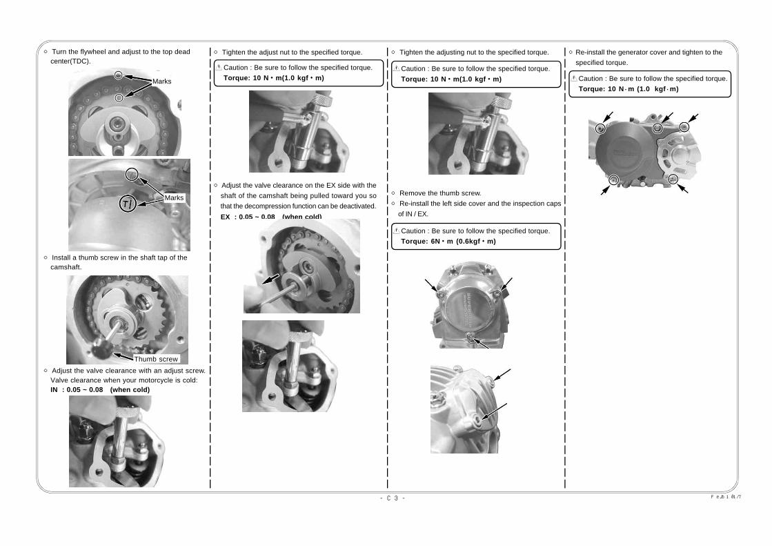
○ Install a thumb screw in the shaft tap of the camshaft.
○ Adjust the valve clearance with an adjust screw. Valve clearance when your motorcycle is cold: IN : 0.05 ~ 0.08 (when cold)
Thumb screw
○ Tighten the adjust nut to the specified torque.
○Adjust the valve clearance on the EX side with the shaft of the camshaft being pulled toward you so that the decompression function can be deactivated.
EX : 0.05 ~ 0.08 (when cold)
○ Tighten the adjusting nut to the specified torque.○ Turn the flywheel and adjust to the top dead center(TDC).
Marks
○ Remove the thumb screw.○ Re-install the left side cover and the inspection caps of IN / EX.
○Re-install the generator cover and tighten to the specified torque.
Marks
Caution : Be sure to follow the specified torque. Torque: 10 N・m (1.0 kgf・m)
Caution : Be sure to follow the specified torque. Torque: 10 N・m(1.0 kgf・m)
Caution : Be sure to follow the specified torque. Torque: 10 N・m(1.0 kgf・m)
Caution : Be sure to follow the specified torque. Torque: 6N・m (0.6kgf・m)

COPY
-C4- Feb./10/’17
○Loosen the adjust part of clutch cable receiver and remove the clutch cable from the clutch release arm.
Clutch cable receiver
Clutch cable
Clutch release arm
Arm spring
Plain washer
Caution : Be sure to follow the specified torque. Torque: 12 N・m (1.2 kgf・m)
○
○
○ ○ ○
○
○○
●Adjusting the slipper clutch
☆Slipper clutch can adjust the timing of start slipping of engine braking by the number of the shim. The more reducing the number of the shim, the more easy to slip the clutch. Because it will be opposite at the accelerating, it can be adjusted by output.○Drain the engine oil.
○Remove the clutch release arm.
○ Remove 6 bolts and remove the R crankcase cover comp.
○Remove 4 pcs of the flange bolts of clutch lifter plate by loosening 2 to 3 times at diagonal position.
Flange bolt
○ Remove the clutch springs and adjust the number of the shim.※As max number of the installable shim is 2, please adjust between 0 to 2.
Shim
○ Attach the clutch spring and attach the lifter plate with 4 pcs of flange bolts by tightening 2 to 3 times at diagonal position with the specified torque.
Flange bolt
※As it will damage the oil seal of lock nut and to be a cause to burn the crankshaft, do not install the R crankcase cover by forcedly.
Caution : Be sure to follow the specified torque. Torque: 7 N・m (0.7 kgf・m)
○ Degrease the mating surface of the right crankcase cover and the crankcase. Then place two dowel pins and a new r crankcase cover gasket.○ Confirm the clutch release rack which is installed inside of the r crankcase cover. Attach the clutch cable receiver with flange bolts by temporary tightening to the crankcase. Then tighten them with the specified torque from the center outward of the crankcase.
6×40
6×40
6×35
6×35 6×35
6×35
6×556×90
6×90
6×55
6×40
clutch cable receiver
Clutch release rack

COPY
-C5- Feb./10/’17
○Attach the adjuster of the clutch cable to the cable receiver, and attach the cable end to the arm so the notch on the split clamp of clutch release arm faces backward.
Clutch cable receiver
Clutch cable
○ Turn the clutch release pinion clockwise until it comes to a halt, and put the plain washer into the
release pinion.
Clutch release arm
Arm spring
Plain washer
Spring
10 N・m (1.0 kgf・m)
○Install the release arm spring on the clutch release arm. Then install the clutch release arm on the release pinion while pulling the cable and install the arm spring on right crankcase cover.
○Attach the flange bolt to the release arm, and tighten the bolt to the specified torque, pressing the arm.
Clutch free play : 10 to 20 mm at the clutch lever end
●Inspection:
○ With the engine turned off, shift the transmission to the first gear. Then, check that the rear wheel rotates when you move the machine, squeezing the clutch lever, and that the rear wheel does not rotate when you have released the clutch lever.○Check the drain bolt is tightened.
10 to 20 mm Clutch lever
Rubber cap
10 N・m (1.0 kgf・m
Rubber cap
○Adjust the free play at the clutch with the adjuster on the clutch cable, then tighten the locking nuts to the specified torque, and cover the clutch cable adjusters at both ends with rubber caps.
Caution : Be sure to follow the specified torque. Torque: 10 N・m (1.0 kgf・m)
Caution : Be sure to follow the specified torque. Torque: 10 N・m (1.0 kgf・m)
Caution : Be sure to follow the specified torque. Torque: 21.5 N・m (2.2 kgf・m)
○Referring to the chart below, choose the engine oil whose viscosity matches the region and outside temperature. (See C2 Oil Change for the specified oil quantity.)
●Rechecking after Installation
○With the engine turned off, shift the transmission to the first gear. And holding the clutch lever, check that the rear wheel rotates when you move the mashine, and that the rear wheel does not rotate when you have released the clutch lever.○Shift the transmission into NEUTRAL, and start the engine.Then check each section for oil leak. If nothing is wrong, do a test run at slow speed in a safe place to check the clutch operation.

COPY
-C6- Feb./10/’17
How to Set the Carburetor
※ Set the carburetor only after warming up the engine, and then test-drive. And use a plug with the right heat value.※ Do the setting in the following manner, studying at what throttle opening position the engine starts failing.
○Jet needle (Throttle position at 1/4 - 3/4) Whether or not the engine revolution is in proportion to the throttle operation ・When the acceleration is not smooth or even, make the air-fuel mixture dense. ・Make the air-fuel mixture lean when the engine revolution goes up heavily and belches black gas. The mixture ratio at this throttle position can be adjusted by the location of E-ring in the grooves. The air-fuel mixture becomes dense as the location of the E-ring moves down from the 1st to the 5th groove.
○Main jet (The throttle position at 3/4 - 4/4) The air-fuel mixture ratio at this throttle position can be adjusted by changing the number of the main jet. The larger the main jet numbers, the denser the mixture ratio becomes. In view of the engine and muffler specifications, select the most appropriate main jet to get the highest revolutions.
○Pilot jet (First of all, please adjust the air screw.) ・In case you have given more than three turns to the air screw to tighten it, use a pilot jet with a small number. ・If you have tighten the air screw (clockwise) to the full, use a pilot jet with a larger number. Check whether you have made a right choice of the pilot jet by seeing if the engine starts up revolving s moothly from the idling to running at slow speed. ・When the engine revolves up unevenly, the pilot jet number is too small. (At idle) ・ When the motorcycle belches black exhaust gas and produces heavy exhaust sound, the pilot jet number is too big. (At idle) ・After replacing the pilot jet, you need to readjust the airscrew.
○Air screw The air screw adjusts the air mass flow at the time of engine’s revolving at slow speed. (At idling) ・Give the air screw a right turn → The air-fuel mixture gets dense. ・Give the air screw a left turn → The air-fuel mixture gets lean. Loosen the tightened air screw back to the 1.5-turn position. And then from this position, give to the airscrew a right or left turn of 1/4 to 1/2 till the engine revolves at the highest speed. Loosen the idle stop screw till you get the steady idling revolutions. And once again adjust the position of the airscrew to get the highest revolutions.
●On how the barometric pressure, temperatures and humidity affect the setting: ・At highlands or at high altitudes, the barometric pressure and air density go down and the air gets into the carburetor in less amounts. This makes the air-fuel mixture dense which was adjusted at low altitudes. ・Under the weather conditions with very low temperatures, the air density increases, which makes the air-fuel mixture lean. ・Under the rainy and humid weather conditions, the air density decreases, which makes the air-fuel mixture dense.
◎Please be informed that, mainly because of improvement in performance, design changes, and cost increase, the product specifications and prices are subject to change without prior notice.◎ This manual should be retained for future reference.
・When the carburetor does not match the engine and the engine fails, the engine failures are caused by either too dense or too lean air-fuel mixture.・The engine failure symptoms for the engine are as follows:
When the air-fuel mixture is too dense: When the air-fuel mixture is too lean:
・The explosion sound with a dull thud continues intermittently.・The engine malfunctions further if you use the choke.・The engine malfunctions when you warm it up.・The engine works well if the cleaner is detached.・The motorcycle belches dense (or, black) exhaust gas.・The plug smolders, getting blackened.
・The engine overheats somewhat.・The engine starts working well If you use the choke,.・The engine does not accelerate well. (No smooth acceleration)・Revolutions change, generating weak power.・The plug burns white.
1段目
4段目2段目
5段目1st groove
2nd groove3rd groove
4th groove
5th groove

COPY
-D1- Feb./10/’17
03-03-0321
VM26 Carburetor PE28 Carburetor
03-03-027
Item Nos Product Names00-03-0151 Pilot jet, # 10 00-03-0152 Pilot jet, # 12.500-03-0153 Pilot jet, # 1500-03-0154 Pilot jet, # 17.500-03-0155 Pilot jet, # 20 00-03-0156 Pilot jet, # 22.5 00-03-0157 Pilot jet, # 25 00-03-0158 Pilot jet, # 27.500-03-0159 Pilot jet, # 30
Item Nos Product Names00-03-0060 Main jet, # 100 00-03-0061 Main jet, # 105 00-03-0062 Main jet, # 110 00-03-0063 Main jet, # 115 00-03-0064 Main jet, # 120 00-03-0065 Main jet, # 125 00-03-0066 Main jet, # 130 00-03-0067 Main jet, # 135 00-03-0068 Main jet, # 14000-03-0069 Main jet, # 145 00-03-0070 Main jet, # 150 00-03-0071 Main jet, # 155 00-03-0072 Main jet, # 160 00-03-0073 Main jet, # 165 00-03-0074 Main jet, # 17000-03-0075 Main jet, # 175 00-03-0076 Main jet, # 180 00-03-0077 Main jet, # 185 00-03-0078 Main jet, # 190 00-03-0079 Main jet, ♯19500-03-0080 Main jet, ♯20000-03-0081 Main jet, ♯21000-03-0082 Main jet, ♯22000-03-0083 Main jet, ♯23000-03-0084 Main jet, ♯24000-03-0085 Main jet, ♯25000-03-0086 Main jet, ♯260
Item Nos Product Names00-03-0137 Slow jet, ♯3500-03-0138 Slow jet, ♯3800-03-0139 Slow jet, ♯4000-03-0140 Slow jet, ♯4200-03-0141 Slow jet, ♯4500-03-0142 Slow jet, ♯4800-03-0143 Slow jet, ♯5000-03-0144 Slow jet, ♯5200-03-0145 Slow jet, ♯5500-03-0146 Slow jet, ♯5800-03-0147 Slow jet, ♯6000-03-0148 Slow jet, ♯6200-03-0149 Slow jet, ♯6500-03-0150 Slow jet, ♯70
Item Nos Product Names Item Nos Product Names00-03-0130 Main jet, #82 00-03-0107 Main jet, #14200-03-0131 Main jet, #85 00-03-0108 Main jet, #14500-03-0132 Main jet, #88 00-03-0109 Main jet, #14800-03-0133 Main jet, #90 00-03-0110 Main jet, #15000-03-0134 Main jet, #92 00-03-0111 Main jet, #15200-03-0135 Main jet, #95 00-03-0112 Main jet, #15500-03-0136 Main jet, #98 00-03-0113 Main jet, #15800-03-0090 Main jet, #100 00-03-0114 Main jet, #16000-03-0091 Main jet, #102 00-03-0115 Main jet, #16200-03-0092 Main jet, #105 00-03-0116 Main jet, #16500-03-0093 Main jet, #108 00-03-0117 Main jet, #16800-03-0094 Main jet, #110 00-03-0118 Main jet, #17000-03-0095 Main jet, #112 00-03-0119 Main jet, #17200-03-0096 Main jet, #115 00-03-0120 Main jet, #17500-03-0097 Main jet, #118 00-03-0121 Main jet, #17800-03-0098 Main jet, #120 00-03-0122 Main jet, #18000-03-0099 Main jet, #122 00-03-0202 Main jet, #18200-03-0100 Main jet, #125 00-03-0123 Main jet, #18500-03-0101 Main jet, #128 00-03-0124 Main jet, #18800-03-0102 Main jet, #130 00-03-0125 Main jet, #19000-03-0103 Main jet, #132 00-03-0126 Main jet, #19200-03-0104 Main jet, #135 00-03-0127 Main jet, #19500-03-0105 Main jet, #138 00-03-0128 Main jet, #19800-03-0106 Main jet, #140 00-03-0129 Main jet, #200
High flow filter
AirAirAir
Shape-maintaining
stainless spring
High flow filter
Pebblesand sand
Pebblesand sand
Insulator
00-03-0210 00-03-0211
58 mm 58 mm
30 m
m
30 m
m
φ34 φ35
φ29 φ29
03-01-106403-01-1094
for MIKUNI VM26for KEIHIN PE28
for VM26 for PE28
For more information, please refer to our parts catalog, or log onto our Web site atURL http://www.takegawa.co.jp
Involute throttle set
Outer length: 710 mm09-02-0230 (Black anodized)09-02-0232 (Gray metallic anodized)
Outer length: 810 mm09-02-0231 (Black anodized)09-02-0233 (Gray metallic anodized)
Standard high throttle set
09-02-0222 (710 mm in outer length)09-02-0221 (810 mm in outer length)
90-bent high throttle set
09-02-021 (700 mm in outer length)
Fuel cock assembly
03-03-001

COPY
-D2- Feb./10/’17
23T 24T 25T 26T 27T 28T 29T 30T 31T 32T 33T 34T 35T 36T12T 1.91 2.00 2.08 2.17 2.25 2.33 2.42 2.50 2.58 2.67 2.75 2.83 2.92 3.0013T 1.76 1.84 1.92 2.00 2.08 2.15 2.23 2.31 2.38 2.46 2.54 2.62 2.69 2.7714T 1.64 1.71 1.79 1.86 1.93 2.00 2.07 2.14 2.21 2.29 2.36 2.43 2.50 2.5715T 1.53 1.60 1.67 1.73 1.80 1.87 1.93 2.00 2.07 2.13 2.20 2.27 2.33 2.4016T 1.43 1.50 1.56 1.62 1.68 1.75 1.81 1.87 1.93 2.00 2.06 2.12 2.18 2.25
For more information, please refer to our parts catalog, or log onto our Web site atURL http://www.takegawa.co.jp
●As removal and installation of a cam shaft on the Super Head 4 VALVE+R is easy, we have prepared 4 kinds of cam shafts. Thus, you can enjoy the customized engine and enhanced riding comfort by selecting a desired transmission and by changing the cam shafts to meet the way of driving such as off-road driving and on-the-road driving.
Cam shaft:10 / 15D auto-decompression cam shaft:15 / 20D auto-decompression cam shaft:20 / 25D auto-decompression cam shaft:25 / 30D auto-decompression cam shaft
00-01-167300-01-167400-01-167500-01-1676
Racing C.D.I. Magnet Kit05-02-0511○ Excellent startup performance because of ignition at low revolution. (Excellent start-up by a kick starter)○Ignition timing adjustable at up to 24 degrees,○Integral ignition coil with built-in CDI unit,○Fully-covered stator coil to protect the ignition coil,○Weight saving: R-type φ58 rotor: 336 g Stator, including cords: 383 g Ignition coil, including cords: 370 g○ “ROSSA” (red) as proof of high performance※No charging functions
Kick starter arm
(Steel-forged) (Aluminum-forged)
02-08-0052 09-10-006(Back step should not be installed.)
Clutch lever assembly
02-01-028 (black)02-01-0282 (silver)
Quick lever ASSY.
02-01-0601
Steel Drive Sprocket
02-05-01 (12T Standard)02-05-02 (13T Standard)02-05-03 (14T Standard)
02-05-041 (15T Racing)02-05-051 (16T Racing)
Aluminum Driven Sprocket
Gear Ratio (Final)
DrivenDrive
Steel Driven Sprocket
02-07-0641 (41T)02-07-0642 (42T)02-07-0643 (43T)
02-07-0011 (25T)02-07-0012 (28T)02-07-0013 (30T)02-07-0014 (33T)
02-07-0007 (23T)02-07-0008 (25T)02-07-0009 (28T)02-07-0010 (23T)
Titanium alloy tappet adjusting nut
Titanium alloy valve spring retainer
00-01-0173
01-12-0110
Made of lightweight and high-strength titanium alloy.We actualized it lightweight by changing not onlymaterial but also the hexagonal width, from 9 to 8 mm.With lightweight, response to the camshaft profile isimproved.
This retainer is made lighter. Thus, response tothe high-revolution is improved.It is made more resistant to corrosion by to havea special coating of the surface.
COPY
-D3- Feb./10/’17
For more information, please refer to our parts catalog, or log onto our Web site atURL http://www.takegawa.co.jp
Cylinder head
Clutch cover07-07-0124
07-07-0125
07-07-012307-07-0107
07-07-0138
07-07-0136
07-07-0135
07-07-0126
Steering Stem mount
3Fin4Line
4Fin5Line
07-07-0139
09-07-2712
Slimline hose 09-07-2708
Rubber hose 09-07-2711
Rubber hose 07-07-0041
Slimline hose 07-07-0043
Frame mount
3Fin4Line
4Fin5Line
Outlet
Oil cooler
Mounting Position
Compact cool
Oil cooler
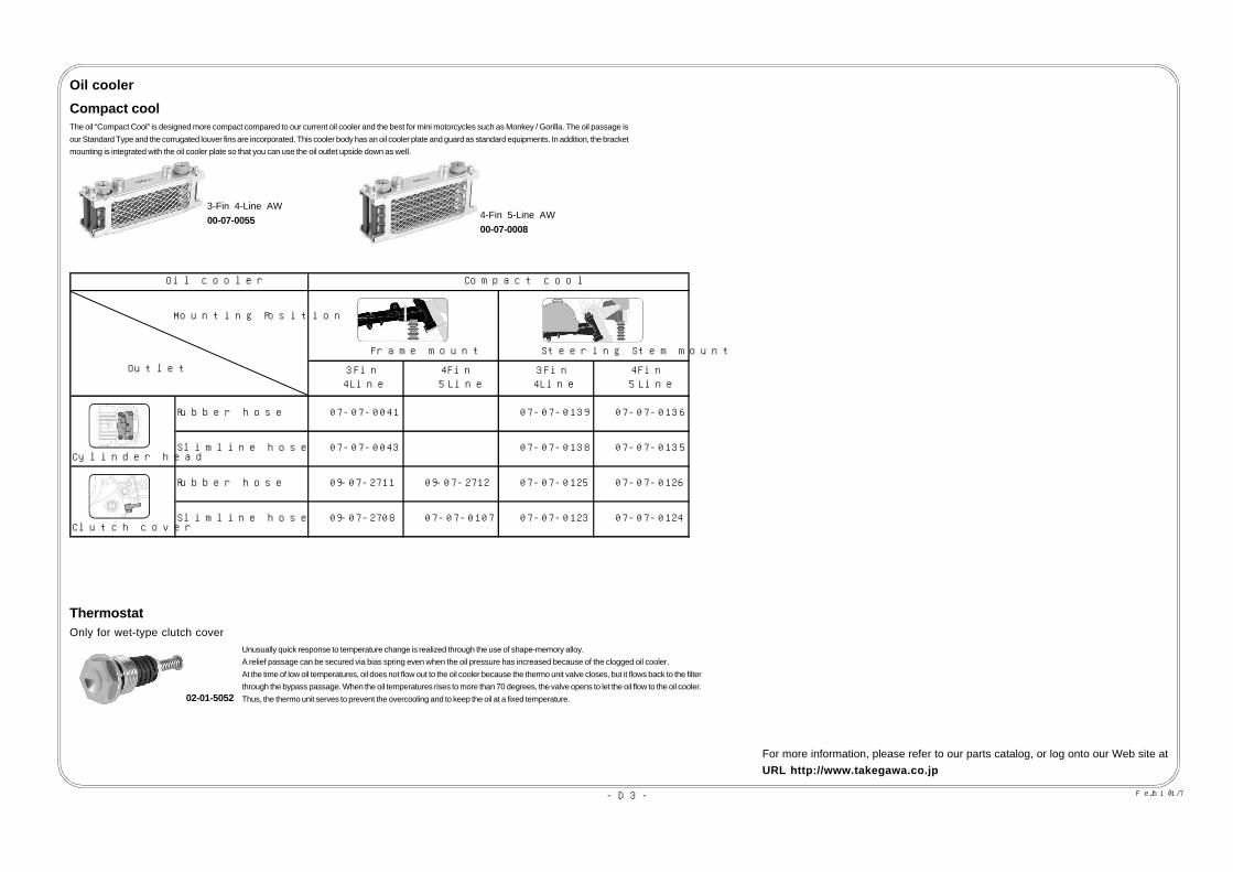
Compact coolThe oil “Compact Cool” is designed more compact compared to our current oil cooler and the best for mini motorcycles such as Monkey / Gorilla. The oil passage isour Standard Type and the corrugated louver fins are incorporated. This cooler body has an oil cooler plate and guard as standard equipments. In addition, the bracketmounting is integrated with the oil cooler plate so that you can use the oil outlet upside down as well.
3-Fin 4-Line AW00-07-0055 4-Fin 5-Line AW
00-07-0008
ThermostatOnly for wet-type clutch cover
02-01-5052
Unusually quick response to temperature change is realized through the use of shape-memory alloy.A relief passage can be secured via bias spring even when the oil pressure has increased because of the clogged oil cooler.At the time of low oil temperatures, oil does not flow out to the oil cooler because the thermo unit valve closes, but it flows back to the filterthrough the bypass passage. When the oil temperatures rises to more than 70 degrees, the valve opens to let the oil flow to the oil cooler.Thus, the thermo unit serves to prevent the overcooling and to keep the oil at a fixed temperature.

COPY
-D4- Feb./10/’17
Oil catch tank
07-05-0010 09-04-032
(cylinder type) (side cover type)
Tank capacity : 420 cc Tank capacity : 550 cc
Front fork
06-01-0732φ 30 Front Fork Set w/Disc brake(For 10-inch ONLY)
06-01-0038φ 27 Front Fork Set w/Disc brake(For 10-inch ONLY)
06-02-0015Top Bridge & Stem
06-02-1002φ27Top Bridge
06-07-0011φ27 Steering Stem
Rear fork
06-03-0116 Aluminum Swingarm (12cm-extended)06-03-0114 Aluminum Swingarm (16cm-extended)06-03-0115 Aluminum Swingarm (16cm-extended) w / Stabilizer
Our original front fork with φ30 inner tube increases the stability ofstroke by damping force generating mechanism of “free-valve” typeand reduces the shock when the front shocks rebound and compress.
Our front fork increases the stability of stroke by using the damped forcegenerating mechanism of “free-valve” type which big motorcycles haveand reduces the shock when the front shocks rebound and compress.
06-01-0723L / R Front Fork Set
00-06-0020L / R Front Fork Set
Both high rigidity and lightweight, which are both essential for swingarm, have beenachieved with the well-balanced structure of our original polygon sectional design andthickness of the material.Moreover, skillful bending and buff finish are excellent and appeal more than others.
For more information, please refer to our parts catalog, or log onto our Web site atURL http://www.takegawa.co.jp
COPY
ImportantIf you got a kickback at the engine start, the engine will be get damaged.In the worst case, it would be broken.In order to prevent an engine kickback, please start the engine by following step.
Lightly press down the kick pedal and find the position that become heavier.Put it back to the first position when become heavier.Keep your foot on the kick pedal, and press it to the bottom quickly at a stretch while keeping the throttlegrip at fully closed.
To open the throttle at the engine start is one of the major causes to occur the kickback.If engine doesn't start, please try several times.If it still cannot be started, there should be other cause.
<Caution>If the engine is broken by the kickback, high repair cost will be charged.
3-5-16 Nishikiorihigashi Tondabayashi Osaka Japan TEL : 81-721-25-1357 FAX : 81-721-24-5059 URL : http://www.takegawa.co.jpCo.,Ltd.
ImportantIf you got a kickback at the engine start, the engine will be get damaged.In the worst case, it would be broken.In order to prevent an engine kickback, please start the engine by following step.
Lightly press down the kick pedal and find the position that become heavier.Put it back to the first position when become heavier.Keep your foot on the kick pedal, and press it to the bottom quickly at a stretch while keeping the throttlegrip at fully closed.
To open the throttle at the engine start is one of the major causes to occur the kickback.If engine doesn't start, please try several times.If it still cannot be started, there should be other cause.
<Caution>If the engine is broken by the kickback, high repair cost will be charged.
3-5-16 Nishikiorihigashi Tondabayashi Osaka JapanTEL : 81-721-25-1357 FAX : 81-721-24-5059 URL : http://www.takegawa.co.jpCo.,Ltd.


![[Www.wangsiteducation.com]SOSHUM 148](https://static.fdocuments.in/doc/165x107/55cf8cd25503462b138fd539/wwwwangsiteducationcomsoshum-148.jpg)


