Engine Assambly
232
ENGINE ASSEMBLY 1336-04 / 1336-25 / 1130-12 / 1610-01 / 1330-01 / 1990-02 / 1990-03 / 1990-11 / 1225-01 / 1214-01 / 1315-01 / 1533-08 / 1533-08 / 1330-40 / 1330-13 ENGINE ASSEMBLY GENERAL INFORMATION SPECIFICATION..................................... TIGHTENING TORQUE......................... CHECK AND INSPECTION.................... GUIDELINES ON ENGINE SERVICE..... 1. 2. 3. 4. OVERVIEW AND OPERATING PROCESS BELT SYSTEM..................................... VACUUM PUMP.................................... ENGINE MOUNTING............................. INTAKE/EXHAUST SYSTEM................ CYLINDER HEAD COVER AND OIL SEPARATOR......................................... CYLINDER HEAD.................................. CHAIN AND GEAR DRIVE SYSTEM...... OIL PAN................................................ MASS BALANCE UNIT (MBU)............... FLYWHEEL AND DRIVE PLATE............ PISTON/CRANKSHAFT/CYLINDER BLOCK.................................................. 1. 2. 3. 4. 5. 6. 7. 8. 9. 10. 11. CONFIGURATION BELT SYSTEM..................................... VACUUM PUMP.................................... ENGINE MOUNTINGS.......................... INTAKE/EXHAUST MANIFOLD............. OIL SEPARATOR.................................. CYLINDER HEAD ASSEMBLY.............. CHAIN DRIVE SYSTEM........................ OIL PAN................................................ MASS BALANCE UNIT (MBU)............... DUAL MASS FLYWHEEL (DMF) AND DRIVE PLATE....................................... PISTON/CONNECTING ROD/ CRANKSHAFT/CYLINDER BLOCK........ 1. 2. 3. 4. 5. 6. 7. 8. 9. 10. 11. REMOVAL AND INSTALLATION 1336-00 TIMING CASE (D20DTF)........... 1336-04 BELT TENSIONER ASSEMBLY... 1336-25 IDLER PULLEY ASSEMBLY NO.1 (NO.2) .......................................... 1130-00 CRANKSHAFT.............................. 1130-12 ISOLATION DAMPER ASSEMBLY.................................. 1610-00 VACUUM PUMP........................... 1610-01 VACUUM PUMP ASSEMBLY....... 3 4 7 12 14 15 16 17 18 19 21 25 26 27 28 29 33 34 36 39 41 46 52 53 54 57 65 66 70 72 73 77 78
-
Upload
sergey-sergeev -
Category
Documents
-
view
61 -
download
4
Transcript of Engine Assambly

ENGINE ASSEMBLY1336-04 / 1336-25 / 1130-12 / 1610-01 / 1330-01 / 1990-02 / 1990-03 / 1990-11 / 1225-01 / 1214-01 / 1315-01 / 1533-08 / 1533-08 / 1330-40 / 1330-13
ENGINE ASSEMBLY
GENERAL INFORMATION
SPECIFICATION.....................................TIGHTENING TORQUE.........................CHECK AND INSPECTION....................GUIDELINES ON ENGINE SERVICE.....
1.2.3.4.
OVERVIEW AND OPERATING PROCESS
BELT SYSTEM.....................................VACUUM PUMP....................................ENGINE MOUNTING.............................INTAKE/EXHAUST SYSTEM................CYLINDER HEAD COVER AND OIL SEPARATOR.........................................CYLINDER HEAD..................................CHAIN AND GEAR DRIVE SYSTEM......OIL PAN................................................MASS BALANCE UNIT (MBU)...............FLYWHEEL AND DRIVE PLATE............PISTON/CRANKSHAFT/CYLINDER BLOCK..................................................
1.2.3.4.5.
6.7.8.9.10.11.
CONFIGURATION
BELT SYSTEM.....................................VACUUM PUMP....................................ENGINE MOUNTINGS..........................INTAKE/EXHAUST MANIFOLD.............OIL SEPARATOR..................................CYLINDER HEAD ASSEMBLY..............CHAIN DRIVE SYSTEM........................OIL PAN................................................MASS BALANCE UNIT (MBU)...............DUAL MASS FLYWHEEL (DMF) AND DRIVE PLATE.......................................PISTON/CONNECTING ROD/ CRANKSHAFT/CYLINDER BLOCK........
1.2.3.4.5.6.7.8.9.10.
11.
REMOVAL AND INSTALLATION
1336-00 TIMING CASE (D20DTF)...........1336-04 BELT TENSIONER ASSEMBLY... 1336-25 IDLER PULLEY ASSEMBLY NO.1 (NO.2) ..........................................1130-00 CRANKSHAFT..............................1130-12 ISOLATION DAMPER ASSEMBLY..................................1610-00 VACUUM PUMP...........................1610-01 VACUUM PUMP ASSEMBLY.......
347
12
14151617
181921252627
28
293334363941465253
54
57
6566
7072
737778

ENGINE ASSEMBLY
REMOVAL AND INSTALLATION
1990-00 ENGINE MOUNTING....................1330-01 ENGINE MOUNTING INSULATOR (LH-MTG) ................1990-02 ENGINE MOUNTING INSULATOR (RH-MTG) ...............1990-03 ENGINE MOUNTING INSULATOR (FRT-MTG) .............1990-11 ENGINE MOUNTING INSULATOR (RR-MTG) ...............1225-00 CYLINDER HEAD COVER AND CAMSHAFT (D20DTF)..................1225-01 CYLINDER HEAD COVER............1214-00 CYLINDER HEAD ASSEMBLY AND CYLINDER HEAD GASKET..1214-01 CYLINDER HEAD ASSEMBLY.....0000-00 ENGINE ASSEMBLY (D20DTF)....1315-00 CHAIN DRIVE...............................1315-01 TIMING CHAIN ASSEMBLY (UPPER CHAIN-BUSH).................1533-08 OIL PAN ASSEMBLY...................1533-08 OIL PAN ASSEMBLY...................1130-00 CRANKSHAFT AND FLYWHEEL..1130-40 MASS BALANCE SHAFT UNIT (MBU)...........................................1130-13 DUAL MASS FLYWHEEL (DMF) ASSEMBLY..................................1120-00 ENGINE OVERHOLE....................
81
82
85
87
89
9192
9697
112127
128137138141
142
144146

02-3
ENGINE ASSEMBLYkorando 2010.10
0000-00
0000-00D20DTF ENGINE
1. SPECIFICATIONUnit Description Specification Remark
Cylinder head Height 142.9 to 143.1 mm
Flatness below 0.1 mm
Valve protrusion Intake valve 0.1 to 0.7 mm
Exhaust valve 0.1 to 0.7 mm
Flatness on manifold side
Intake manifold 0.08 mm
Exhaust manifold 0.08 mm
Mass Balance Unit (MBU)
Backlash 0.05 to 0.15 mm
Connecting rod End play 0.5 to 1.5 mm
Camshaft Axial end play Intake 0.1 to 0.35 mm
Exhaust 0.1 to 0.35 mm
Camshaft position sensor
Distance between Camshaft position sensor and sprocket
0.20 to 1.80 mm
Valve Clearance between valve
and piston
Intake Approx. 0.7 mm
Exhaust Approx. 0.8 mm
Valve recess Intake 0.1 to 0.7 mm
Exhaust
Cylinder block Piston protrusion 0.541 to 0.649 mm
Piston ring TOP ring end gap 0.20 to 0.35 mm
2nd ring end gap 0.35 to 0.50 mm
3rd ring end gap 0.2 to 0.40 mm
Offset 0.3 mm
Head gasket Piston protrusion 0.475~0.540 1.2t
0.541 to 0.649 1.3t
0.650 to 0.745 1.4t

02-4
korando 2010.10
0000-00
ENGINE ASSEMBLY
2. TIGHTENING TORQUEComponent Size Bolt
QuantitySpecified torque
(Nm)Remark
(Total torque)
Main bearing cap M11×62 (small)M11×67 (large)
10 55±5 Nm,130˚+10˚
80 to 130 Nm
Connecting rod cap M9×52 8 40±5 Nm,90˚+10˚
50 to 80 Nm
Rear cover M6×20 6 10 ± 1 Nm
Timing gear cover M6×55 3 10 ± 1 Nm
M6×45 8 10 ± 1 Nm
Oil pump M8×35SOC 3 25 ± 2.5 Nm
Flywheel M10×22 8 45 ± 5 Nm,90˚+10˚
60 to 100 Nm
Crankshaft center bolt M18×50 1 200 ± 20 Nm,180˚+20˚
660 to 720 Nm
Oil pan M6×20 18 10 ± 1 Nm
M6×35 2 10 ± 1 Nm
M6×85 2 10 ± 1 Nm
M6×120 2 10 ± 1 Nm
M8×40 2 25 ± 2.5 Nm
HP pump main nut M14×1.5-8-1 1 65 ± 5 Nm
HP pump bolt M8×55 3 25 ± 2.5 Nm
Cylinder head M12×177 12 85 ± 8.5 Nm + 270° ± 10°
Camshaft cap M6× 16 10 ± 1 Nm
M8× 4 25 ± 2.5 Nm
Exhaust stud bolt 10 40 ± 4 Nm
Exhaust sprocket bolt M11×40 1 30 ± 3 Nm
Screw bolt M24 1 25 ± 2.5 Nm
Coolant temperature sensor
1 20 ± 2.0 Nm
Auto tensioner M7×45 (Low) 1 25 ± 2.5 Nm
M12×90 (Up) 1 55 ± 5.5 Nm
Coolant pump M6×50 7 10 ± 1.0 Nm
02-5
ENGINE ASSEMBLYkorando 2010.10
0000-00
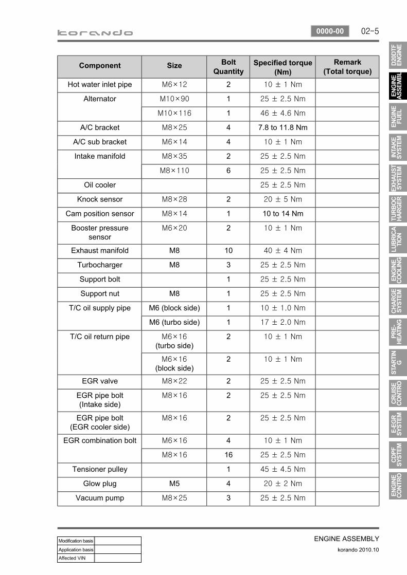
Component Size Bolt Quantity
Specified torque (Nm)
Remark(Total torque)
Knock sensor M8×28 2 20 ± 5 Nm
Cam position sensor M8×14 1 10 to 14 Nm
Booster pressure sensor
M6×20 2 10 ± 1 Nm
Exhaust manifold M8 10 40 ± 4 Nm
Turbocharger M8 3 25 ± 2.5 Nm
Support bolt 1 25 ± 2.5 Nm
Support nut M8 1 25 ± 2.5 Nm
T/C oil supply pipe M6 (block side) 1 10 ± 1.0 Nm
M6 (turbo side) 1 17 ± 2.0 Nm
T/C oil return pipe M6×16 (turbo side)
2 10 ± 1 Nm
M6×16 (block side)
2 10 ± 1 Nm
EGR valve M8×22 2 25 ± 2.5 Nm
EGR pipe bolt(Intake side)
M8×16 2 25 ± 2.5 Nm
EGR pipe bolt(EGR cooler side)
M8×16 2 25 ± 2.5 Nm
EGR combination bolt M6×16 4 10 ± 1 Nm
M8×16 16 25 ± 2.5 Nm
Tensioner pulley 1 45 ± 4.5 Nm
Glow plug M5 4 20 ± 2 Nm
Vacuum pump M8×25 3 25 ± 2.5 Nm
Component Size Bolt Quantity
Specified torque (Nm)
Remark(Total torque)
Hot water inlet pipe M6×12 2 10 ± 1 Nm
Alternator M10×90 1 25 ± 2.5 Nm
M10×116 1 46 ± 4.6 Nm
A/C bracket M8×25 4 7.8 to 11.8 Nm
A/C sub bracket M6×14 4 10 ± 1 Nm
Intake manifold M8×35 2 25 ± 2.5 Nm
M8×110 6 25 ± 2.5 Nm
Oil cooler 25 ± 2.5 Nm

02-6
korando 2010.10
0000-00
ENGINE ASSEMBLY
Component Size Bolt Quantity
Specified torque (Nm)
Remark(Total torque)
Oil gauge tube M6×16 1 10 ± 1 Nm
Oil filter M8×35SOC 1 25 ± 2.5 Nm
Fuel rail M8×35SOC 2 25 ± 2.5 Nm
Injector clamp bolt M6×60 2 10 ± 1 Nm,120˚+10˚
High pressure pipe (between HP pump and
fuel rail)
M17 1 30 ± 3 Nm
High pressure pipe (between fuel rail and
injector )
M17 4 30 ± 3 Nm
Crank position sensor M5×14 1 8 ± 0.4 Nm
Main wiring M6×16 5 10 ± 1 Nm
Intake duct bracket M8×16 3 25 ± 2.5 Nm
Power steering pump M8×100 3 25 ± 2.5 Nm
Component Size Bolt Quantity
Specified torque (Nm)
Remark(Total torque)
Cooling fan bracket
M6×25 5 10 ± 1 Nm
M6×60 1 10 ± 1 Nm
M6×85 3 10 ± 1 Nm
Cylinder head cover M6×35 21 10 ± 1 Nm

02-7
ENGINE ASSEMBLYkorando 2010.10
0000-00
3. CHECK AND INSPECTION1) Cylinder(1) Compression pressure test
Specified value▶
Compression ratio 16.5 : 1
Test condition at normal operating temperature (80˚C)
Compression pressureStandard 32 bar
Minimum 18 bar
Differential limit between cylinders Maximum 3 bar
The compression pressure test is to check the conditions of internal components (piston, piston ring, intake and exhaust vale, cylinder head gasket). This test provides current engine operating status.
Before cranking the engine, make sure that the test wiring, tools and persons are keeping away from moving components of engine (e.g., belt and cooling fan).Park the vehicle on the level ground and apply the parking brake.Do not allow anybody to be in front of the vehicle.
-
-
-
Warm the engine up to normal operating temperature (80°C).
Disconnect the fuel rail pressure sensor connector to cut off the fuel injection.Place the diagram sheet to compression pressure tester.
1.
2.
3.

02-8
korando 2010.10
0000-00
ENGINE ASSEMBLY
Remove the glow plugs and install the compression pressure tester into the plug hole.
4.
Crank the engine for approx. 10 seconds by using the start motor.Record the test result and measure the compression pressure of other cylinders with same manner.If the measured value is out of specified value, perform the cylinder pressure leakage test.
5.
6.
7.
(2) Cylinder pressure leakage test
Test condition: normal engine operating temperature (80˚C)
Specified value
Whole engine below 25%
at valve and cylinder head gasket below 10%
at piston ring below 20%
If the measured value of the compression pressure test is not within the specifications, perform the cylinder pressure leakage test.
Specified value▶
Perform this test in the sequence of firing order.Do not test the cylinder pressure leakage with wet type test procedure. (do not inject the engine oil into the combustion chamber)
-
-

02-9
ENGINE ASSEMBLYkorando 2010.10
0000-00
Position the piston at TDC and measure the piston protrusion from crank case mating surface.
(3) Piston protrusion check
Specified value 0.541 to 0.649 mm
Measure it at both ends of crankshaft.-
02-10
korando 2010.10
0000-00
ENGINE ASSEMBLY
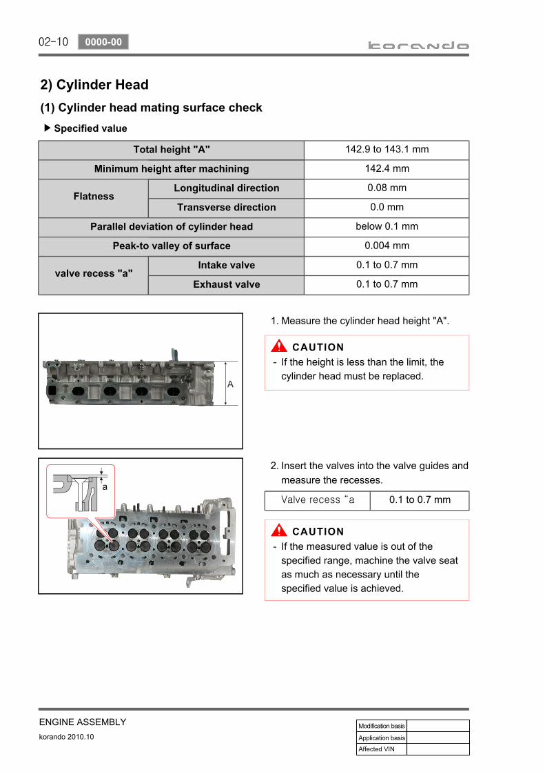
2) Cylinder Head(1) Cylinder head mating surface check
Specified value▶
Total height "A" 142.9 to 143.1 mm
Minimum height after machining 142.4 mm
FlatnessLongitudinal direction 0.08 mm
Transverse direction 0.0 mm
Parallel deviation of cylinder head below 0.1 mm
Peak-to valley of surface 0.004 mm
valve recess "a"Intake valve 0.1 to 0.7 mm
Exhaust valve 0.1 to 0.7 mm
Measure the cylinder head height "A".1.
Insert the valves into the valve guides and measure the recesses.
2.
Valve recess “a 0.1 to 0.7 mm
If the height is less than the limit, the cylinder head must be replaced.
-
If the measured value is out of the specified range, machine the valve seat as much as necessary until the specified value is achieved.
-

02-11
ENGINE ASSEMBLYkorando 2010.10
0000-00
(2) Cylinder head pressure Leak testRemoval of cylinder headRemoval of intake and exhaust manifoldRemoval of valves
---
Place the pressure plate on a flat-bed work bench.
1.
Examine the cylinder head for air bubbling. If the air bubbles are seen, replace the cylinder head.
-
Install the cylinder head on the pressure plate.
2.
Immerse the cylinder head with the pressure plate into warm water (approx. 60°C) and pressurize with compressed
air to 2 bar.
3.

02-12
korando 2010.10
0000-00
ENGINE ASSEMBLY
4. GUIDELINES ON ENGINE SERVICETo prevent personal injuries and vehicle damages that can be caused by mistakes during engine and unit inspection/repair and to secure optimum engine performance and safety after service works, basic cautions and service work guidelines that can be easily forgotten during engine service works are described in.
Cautions before service worksD20DTF engine is for FF (Front Engine Front Drive) type vehicle. Therefore, there are some deferent maintenance and repair works compared to the engine for FR (Front Engine Rear Drive) type vehicle.For safe and correct works, you must observe the working procedures and instructions in this manual. And, use the designated tools as follow:: Power train mounting stand / Engine hanger / Engine stand / Heavy duty engine jackBefore work on engine and each electrical equipment, be sure to disconnect battery negative (-) terminal.Before service works, be sure to prepare the works by cleaning and aligning work areas.Always position the ignition switch to OFF if not required. If not, there can be electrical equipment damages or personal injuries due to short-circuit or ground by mistake.There should be no leak from fuel injection system (HP pump, fuel hose, high pressure pipe) of the D20DTF engine. So they should be protected from foreign materials.While removing the engine, do not position the jack and others under the oil pan or engine. To secure the safety, use only safety hook on the engine.When removing the engine, use only the safety hook on engine and engine hanger. Do not support it with jack under the oil pan.
▶
-
--
-
-
-
Engine has a lot of precise portions so tightening torque should be correct during disassembly/assembly and removal/installation and service work should be done in clean ways during disassembly/assembly. Maintaining working area clean and cautious service administration is essential element of service works while working on the engine and each section of the vehicle. So the mechanics should well aware of it.
While removing the engine, related parts (bolts, gaskets, etc.) should be aligned as a group.While disassembling/assembling internal components of the engine, well aware of disassembly/assembly section in this manual and clean each component with engine oil and then coat with oil before installation.While removing engine, drain engine oil, coolant and fuel in fuel system to prevent leakage.During service work of removal/installation, be sure to check each connected portions to engine not to make interference.
--
--
Engine and accessories▶
02-13
ENGINE ASSEMBLYkorando 2010.10
0000-00
Electrical equipment▶
Electrical equipment should be handled more carefully.Currently, the engine is equipped with a lot of electrical equipments so there can be engine performance drops, incomplete combustion and other abnormal symptoms due to short and poor contact. Mechanics should well aware of vehicle's electrical equipment.
If have to work on the electrical equipment, be sure to disconnect battery negative (-) terminal and position the ignition switch to off if not required.When replacing electrical equipment, use the same genuine part and be sure to check whether ground or connecting portions are correctly connected during installation. If ground or connecting portion is loosened, there can be vehicle fire or personal injury.
-
-
Fuel and lubrication system▶
Painted surface of the body can be damaged or rubber products (hose) can be corroded if engine oil and fuel are spilled over. If spilled over engine, foreign materials in air can be accumulated on the engine damaging fuel system.
If work on the fluid system such as fuel and oil, working area should be well ventilated and mechanic should not smoke.Gasket or seal on the fuel/lubrication system should be replaced with new and bolts and nuts should be tightened as specified.After removal/installation works, be sure to check whether there is leak on the connecting section.
-
-
-
If fine dust or foreign material enters into DI engine's fuel system, there can be serious damages between HP pump and injectors. So, be sure to cover removed fuel system components with cap and protect removed parts not to be contaminated with dirt. (Refer to cleanness in this manual while working on DI engine fuel system)

02-14
korando 2010.10
0000-00
ENGINE ASSEMBLY
with EPS (electric power steering)
1. BELT SYSTEMThe belt system is a single belt drive system which uses single belt and has components on the oil filter housing as FEAD (Front End Accessories Drive) type.
Components▶
HPS EPS
1 Crankshaft pulley (DDU)
2 Auto tensioner
3 Tensioner pulley
4 Vacuum pulley
5 A/C compressor pulley
6 Alternator pulley
7 Water pump pulley
8 NO. 1 idler pulley
9 NO. 2 idler pulley
10 Power steering pump NO. 3 idler pulley
with HPS (hydraulic power steering)

02-15
ENGINE ASSEMBLYkorando 2010.10
0000-00
EGR cooler bypass valve
Exhaust gas goes to combustion chamber without through EGR cooler in engine cooled, and the valve is closed by vacuum pressure.
2. VACUUM PUMPVacuum pump generates the vacuum pressure and supplies it to EGR cooler bypass solenoid. This pump is single vane type and displacement is 210 cc/rev. The lubrication oil is supplied through the hole in hollow shaft.
Components▶
Vacuum pump
Pump capacity: 210 cc/rev Speed: 700 to 6,000 rpm Lubrication temperature: -40 to 155°COil: 5W30Drive type: Driven by exhaust Camshaft sprocket
Brake booster

02-16
korando 2010.10
0000-00
ENGINE ASSEMBLY
Right mounting assemblyLocation: Engine block side and body side
member
Location Right mounting
Front mounting assemblyLocation: Front side of transfer axle housing
and front side of sub frame
Location Front mounting
Left mounting assemblyLocation: Upper side of transfer axle housing
and body side member
Location Left mounting
Rear mounting assemblyLocation: Rear side of transfer axle housing
and front side of sub frame
Location Rear mounting
3. ENGINE MOUNTINGSD20DTF engine mounting is 4-point mounting type and supports the engine and transaxle.Front and rear mountings are rubber type and support the torque reaction. Left and right mountings support the power train rods and torque reaction. Additionally, left mounting is hydraulic type and supports the engine vibration.
Components▶

02-17
ENGINE ASSEMBLYkorando 2010.10
0000-00
4. INTAKE/EXHAUST SYSTEM1) Intake ManifoldIntake manifold is installed on the cylinder head with 8 bolts. The variable swirl valve is introduced to improve the EGR gas mixture and turbulence in combustion chamber and to decrease the exhaust gas.
2) Exhaust ManifoldExhaust manifold is installed on the cylinder head with 10 stud bolts and nuts. EGR port is integrated in cylinder head.
Components▶
Intake manifold
Exhaust manifold
Components▶

02-18
korando 2010.10
0000-00
ENGINE ASSEMBLY
5. CYLINDER HEAD COVER AND OIL SEPARATORThe cylinder head cover is made by high strength plastic to reduce the weight. The multi twist type oil separator improves the oil consumption.
Components▶
Oil separator
PCV valve

02-19
ENGINE ASSEMBLYkorando 2010.10
0000-00
6. CYLINDER HEADCylinder head contains cam position sensor, vacuum pump, intake manifold, exhaust manifold and valve assembly. Vacuum pump and the high pressure (HP) pump are driven by Camshaft and valves are install in vertical direction. This enables the compact layout in cylinder head assembly.

02-20
korando 2010.10
0000-00
ENGINE ASSEMBLY
Camshaft sprocketIntake/exhaust CamshaftsFinger follower & HLA
Components▶
Vacuum pump drive
Cylinder head
Camshaft position sensor HP pump drive gear
Cylinder head gasket
02-21
ENGINE ASSEMBLYkorando 2010.10
0000-00
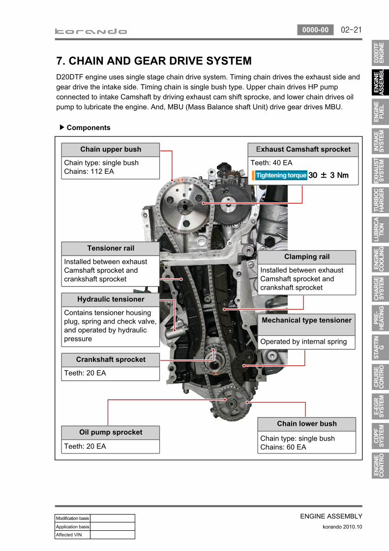
Chain upper bush
Chain type: single bushChains: 112 EA
Tensioner rail
Installed between exhaust Camshaft sprocket and crankshaft sprocket
Hydraulic tensioner
Contains tensioner housing plug, spring and check valve, and operated by hydraulic pressure
Crankshaft sprocket
Teeth: 20 EA
Oil pump sprocket
Teeth: 20 EA
Exhaust Camshaft sprocket
Teeth: 40 EA
Clamping rail
Installed between exhaust Camshaft sprocket and crankshaft sprocket
Mechanical type tensioner
Operated by internal spring
Chain lower bush
Chain type: single bushChains: 60 EA
7. CHAIN AND GEAR DRIVE SYSTEMD20DTF engine uses single stage chain drive system. Timing chain drives the exhaust side and gear drive the intake side. Timing chain is single bush type. Upper chain drives HP pump connected to intake Camshaft by driving exhaust cam shift sprocke, and lower chain drives oil pump to lubricate the engine. And, MBU (Mass Balance shaft Unit) drive gear drives MBU.
Components▶

02-22
korando 2010.10
0000-00
ENGINE ASSEMBLY
Intake/exhaust Camshaft assembly
Components▶
Intake Camshaft
HP pump drive gearExhaust Camshaft
Connected to vacuum pump
02-23
ENGINE ASSEMBLYkorando 2010.10
0000-00
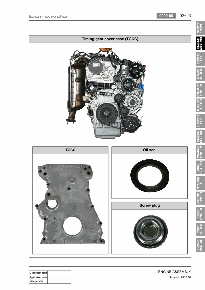
Timing gear cover case (TGCC)
TGCC Oil seal
Screw plug

02-24
korando 2010.10
0000-00
ENGINE ASSEMBLY
Mass Balance Unit (MBU)
Fuel HP pump
HP pump gear
HP pump drive gear
Crankshaft MBU drive gear
MBU

02-25
ENGINE ASSEMBLYkorando 2010.10
0000-00
Oil pan assembly
8. OIL PANThe oil pan in D20DTF engine improves the noise and vibration. Especially, the oil drainage is very easier than before. The oil level sensor in oil pan monitors the oil level and turns on the oil level warning lamp on the meter cluster when the oil level goes down below the specified value. And, A/C compressor bracket and the oil dipstick tube are mounted on the oil pan.
Components▶
Oil drain plug Dust cover
Oil dipstick tube hole
A/C compressor bracket
Oil level sensor
For details, refer to Chapter "Engine Control"

02-26
korando 2010.10
0000-00
ENGINE ASSEMBLY
9. MASS BALANCE SHAFT UNIT (MBU)The balance shaft in MBU (Mass Balance shaft Unit) improves the NVH performance by decreasing the unbalanced force.
Components▶
Crankshaft drive gear
Mass balance shaft unit
Mass balance shaft unit

02-27
ENGINE ASSEMBLYkorando 2010.10
0000-00
10. FLYWHEEL AND DRIVE PLATE1) DMF (Dual Mass Flywheel)The dual mass flywheel, or DMF, eliminates excessive transmission gear rattle, reduces gear change/shift effort, and increases fuel economy. There is a friction ring located between the inner and outer flywheel that allows the inner and outer flywheel to slip. This feature is designed to alleviate any damage to the transmission when torque loads exceed the vehicle rating of the transmission. The friction ring is the weak spot in the system and can wear out if excessive engine torque loads are applied through it. The system also has a center support bearing that carries the load between the inner and outer flywheel, and is fitted with damper springs to absorb shocks.
2) Drive PlateDrive plate receives the power from the start motor when starting the engine. With this, the drive plate initially drives the power train system. And, it is connected to the torque converter to transfer the engine torque to the power train system.
Components▶
Dual mass flywheel
Trigger ring
Drive plate
Components▶

02-28
korando 2010.10
0000-00
ENGINE ASSEMBLY
11. PISTON/CRANKSHAFT/CYLINDER BLOCKThis vehicle is FF driving type and the engine is installed in lateral direction. The crankshaft and the cylinder block convert the compression pressure to the rotating energy.
Components▶
Cylinder block
Piston
Connecting rodCrankshaft

02-29
ENGINE ASSEMBLYkorando 2010.10
0000-00
1. BELT SYSTEM
The strut type tensioner automatically adjusts the belt tension to provide the reliability and durability for the system. And, the belt tension is decreased to minimize the friction loss and improve the belt operating noise.
1) Crankshaft Pulley (Isolation Damper)(1) Overview
(2) Sectional drawing
Axial & radial bearing
Sleeve
Hub
Isolation pulley rubber
Pulley
Damper rubber
Inertia ring

02-30
korando 2010.10
0000-00
ENGINE ASSEMBLY
(3) FeaturesRubber damper: Decrease crankshaft torsionImprove belt NHV: Reduce unbalance speed to crankshaft due to irregular combustionMinimize noise: Anti-vibration from crankshaft and beltPost bonded type rubber damper: Improve durability of rubber damper
1.2.3.4.

02-31
ENGINE ASSEMBLYkorando 2010.10
0000-00
2) Pivot Damped Tensioner(1) OverviewThe torque deviation from crankshaft affects the components in belt drive system and the belt movement. The auto tensioner system is to adjust this deviation automatically. In D20DTF engine, one of the mechanical tensioner, pivot damped tensioner is used to keep the damping force, system reliability and durability. The single belt drive system needs to use the automatic belt tensioning device to transfer the power to pulleys effectively. To get this, the tensioner uses the spring and damping unit.
(2) Mounting Location
Pivot damped tensioner

02-32
korando 2010.10
0000-00
ENGINE ASSEMBLY
for EPS
Belt length: 1,980 mm
3) Belt(1) BeltThe belt length for EPS (Electric Power Steering) equipped vehicle is identical with that for HPS (Hydraulic Power Steering) equipped vehicle. In EPS equipped vehicle, No. 3 idler pulley is installed instead of the hydraulic pump pulley.
(2) Mounting Location
for HPS
Belt length: 1,980 mm
Power steering pump pulley No.3 idler pulley (No power steering pump)

02-33
ENGINE ASSEMBLYkorando 2010.10
0000-00
2. VACUUM PUMP1) Overview and Location
Vacuum pump generates the vacuum pressure and supplies it to EGR cooler bypass solenoid. This pump is single vane type and its displacement is 210 cc/rev. The lubrication oil is supplied through the hole in hollow Camshaft.
2) OperationVacuum pump is driven by exhaust Camshaft.
Connecting are for vacuum pump coupling and exhaust Camshaft slot
Oil supply
Vacuum pump Exhaust Camshaft

02-34
korando 2010.10
0000-00
ENGINE ASSEMBLY
Right mounting assemblyLocation: Engine block side and body side
member
Location Right mounting
3. ENGINE MOUNTING1) Mounting Location
Front mounting assemblyLocation: Front side of transfer axle housing
and front side of sub frame
Location Front mounting
Left mounting assemblyLocation: Upper side of transfer axle housing
and body side member
Location Left mounting
Rear mounting assemblyLocation: Rear side of transfer axle housing
and front side of sub frame
Location Rear mounting

02-35
ENGINE ASSEMBLYkorando 2010.10
0000-00
2) FunctionAppearance Type and function
Front mounting: Bracket + Insulator Type: Rubber type mountingFunction: support torque reaction
Rear mounting: Bracket + Insulator Type: Rubber type mountingFunction: support torque reaction
Left mounting: Bracket + Insulator Type: Rubber type mountingFunction: - support power train rod- support torque reaction
Rear mounting: Bracket + Insulator and D-damper Type: Hydraulic type mountingFunction: - support power train rod- power train bounce vibration absorber- support torque reaction
02-36
korando 2010.10
0000-00
ENGINE ASSEMBLY
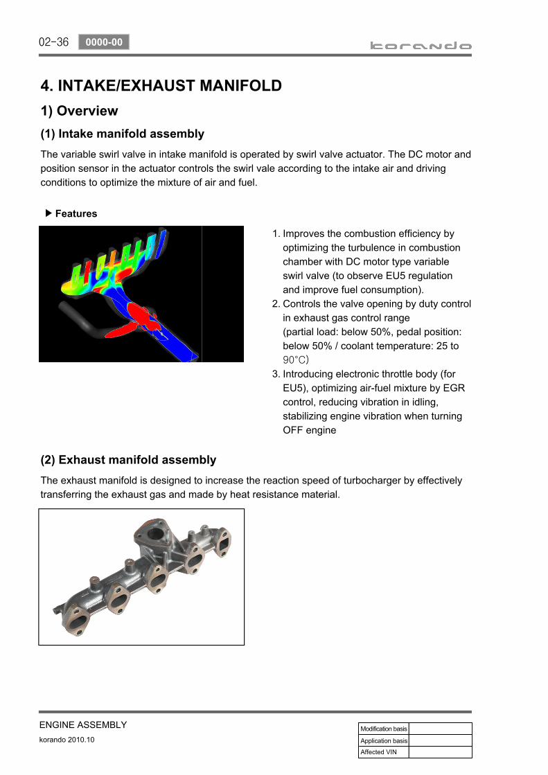
4. INTAKE/EXHAUST MANIFOLD1) Overview(1) Intake manifold assemblyThe variable swirl valve in intake manifold is operated by swirl valve actuator. The DC motor and position sensor in the actuator controls the swirl vale according to the intake air and driving conditions to optimize the mixture of air and fuel.
Improves the combustion efficiency by optimizing the turbulence in combustion chamber with DC motor type variable swirl valve (to observe EU5 regulation and improve fuel consumption). Controls the valve opening by duty control in exhaust gas control range (partial load: below 50%, pedal position: below 50% / coolant temperature: 25 to 90°C)
Introducing electronic throttle body (for EU5), optimizing air-fuel mixture by EGR control, reducing vibration in idling, stabilizing engine vibration when turning OFF engine
1.
2.
3.
(2) Exhaust manifold assemblyThe exhaust manifold is designed to increase the reaction speed of turbocharger by effectively transferring the exhaust gas and made by heat resistance material.
Features▶
02-37
ENGINE ASSEMBLYkorando 2010.10
0000-00
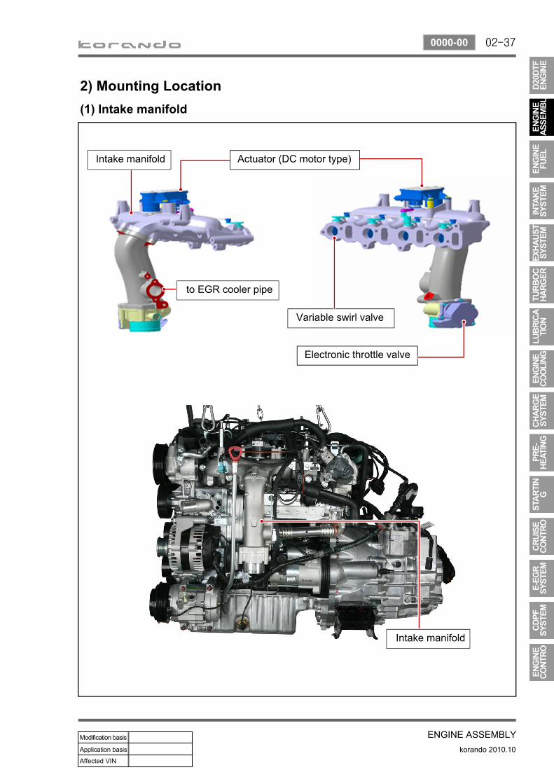
2) Mounting Location(1) Intake manifold
Intake manifold
to EGR cooler pipe
Variable swirl valve
Electronic throttle valve
Intake manifold
Actuator (DC motor type)

02-38
korando 2010.10
0000-00
ENGINE ASSEMBLY
(2) Exhaust manifold
Exhaust manifold
Head protector Exhaust manifold gasket
Cylinder head
EGR cooler port
Cylinder head cover
02-39
ENGINE ASSEMBLYkorando 2010.10
0000-00
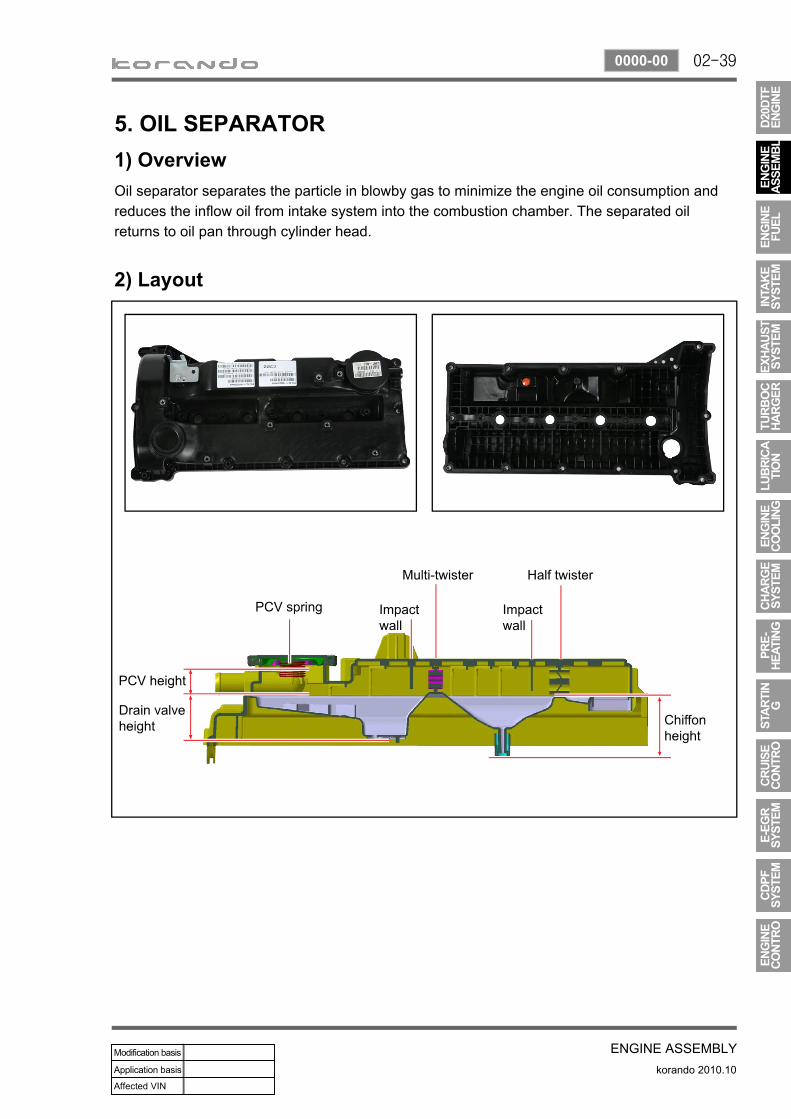
5. OIL SEPARATOR1) OverviewOil separator separates the particle in blowby gas to minimize the engine oil consumption and reduces the inflow oil from intake system into the combustion chamber. The separated oil returns to oil pan through cylinder head.
2) Layout

02-40
korando 2010.10
0000-00
ENGINE ASSEMBLY
3) OperationThe first separation will happen when blowby gas passes through the high efficiency Half-twister in cylinder head cover. Then the gas will be separated at Multi-twister. Separated oil returns to oil pan and gas flows into intake manifold through PCV valve.

02-41
ENGINE ASSEMBLYkorando 2010.10
0000-00
6. CYLINDER HEAD ASSEMBLY1) Cylinder Head(1) OverviewThe cylinder is made by gravity casting and the water jacket is integrated type. The cylinder oil passage is drilled and sealed by cap.The Camshaft bearing cap is also made by casting and installed on the cylinder head.
(2) Features
Closed flow type water jacket (improving cooling performance)▶
02-42
korando 2010.10
0000-00
ENGINE ASSEMBLY
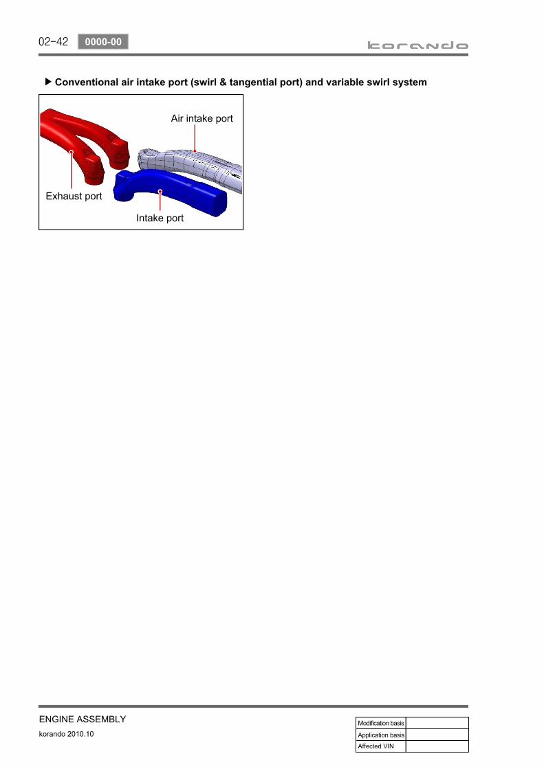
Conventional air intake port (swirl & tangential port) and variable swirl system▶
Air intake port
Intake port
Exhaust port

02-43
ENGINE ASSEMBLYkorando 2010.10
0000-00
Intake/Exhaust Camshafts
2) Camshaft(1) OverviewHollow type Camshaft contains cam, octagon cam, HP pump gear and intake/exhaust gears.Camshaft operates the intake/exhaust valves, vacuum pump and HP pump, and transfers the engine oil to vacuum pump through the internal oil passage.
(2) Mounting Location
Exhaust Camshaft
HP pump drive gear
Octagon cam
Thrust journal
Connected to vacuum pump
Intake Camshaft
Vacuum pump HP pump

02-44
korando 2010.10
0000-00
ENGINE ASSEMBLY
3) Valve Assembly (Installed in Cylinder Head)(1) Features
Automatic valve clearance adjuster by hydraulic pressure (Maintenance Free) - Hydraulic lash Optimized adjustment of valve clearance reduces the valve noise. Roller type finger follower reduces the friction loss. Simple and compact design reduces the moving operation (improving valve following and fuel consumption at high speed)
1.2.3.4.
(2) Arrangement
Hydraulic lash adjuster
Upper valve spring retainer
Lower valve spring retainer
Valve spring
Exhaust valve Intake valve
Finger follower

02-45
ENGINE ASSEMBLYkorando 2010.10
0000-00
4) Cylinder Head Gasket(1) Features
Sealing the cylinder gas pressure - Peak pressure: 190 barMinimizing the distortion of engine structure (cylinder head, block): profile stopper, backland stopperMaterial: MLS (Multi Layer Steel), Gasket (3 layers)Thickness of gasket: 3 types (1.2 /1.3 /1.4 mm)
1.2.
3.4.
(2) Thickness of cylinder head gasket
There are three types of gasket to managing the compression ratio.
Piston protrusion▶
Piston protrusion Thickness
0.475 to 0.540 mm 1.2t
0.541 to 0.649 mm 1.3t
0.650 to 0.745 mm 1.4t
Thickness marking
Ex: 1.3t
02-46
korando 2010.10
0000-00
ENGINE ASSEMBLY
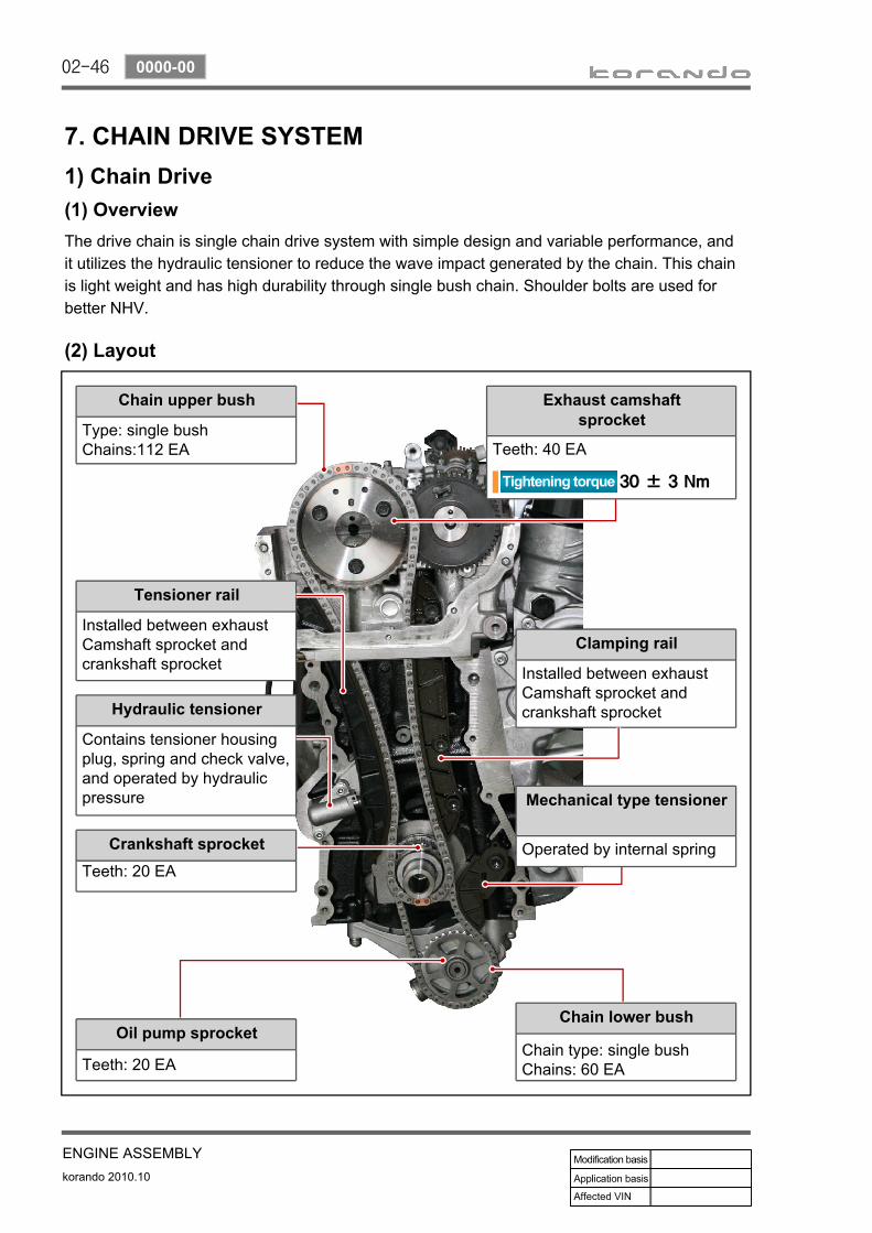
7. CHAIN DRIVE SYSTEM1) Chain Drive(1) OverviewThe drive chain is single chain drive system with simple design and variable performance, and it utilizes the hydraulic tensioner to reduce the wave impact generated by the chain. This chain is light weight and has high durability through single bush chain. Shoulder bolts are used for better NHV.
(2) Layout
Chain upper bush
Type: single bushChains:112 EA
Tensioner rail
Installed between exhaust Camshaft sprocket and crankshaft sprocket
Hydraulic tensioner
Contains tensioner housing plug, spring and check valve, and operated by hydraulic pressure
Crankshaft sprocketTeeth: 20 EA
Oil pump sprocket
Teeth: 20 EA
Clamping rail
Installed between exhaust Camshaft sprocket and crankshaft sprocket
Chain lower bush
Chain type: single bushChains: 60 EA
Mechanical type tensioner
Operated by internal spring
Exhaust camshaft sprocket
Teeth: 40 EA

02-47
ENGINE ASSEMBLYkorando 2010.10
0000-00
2) Timing Chain and Gear(1) Timing chain
Simple layout: optimized timing, enhanced NVHSingle stage layout: minimized chain load
-
-
Chain upper bush - Single bush type (112 EA)Chain lower bush - Single bush type (60 EA)
(2) TensionerTensioner adjusts the chain tension to keep it tight during engine running. This reduces the wear in guide rail and spoke.
Operating principle- Use the spring tension in tensioner and hydraulic pressureTensioner type- Compensation and impact absorbingStatic and dynamic force- Spring + Hydraulic pressure
1.
2.
3.
Plunger
Housing Spring
Check valve
Hydraulic tensioner assembly▶

02-48
korando 2010.10
0000-00
ENGINE ASSEMBLY
(3) Mechanical Tensioner AssemblyOperating principle- Use only spring tensionTensioner type- Compensation and impact absorbingStatic and dynamic force- Spring
(4) Guide railThe guide rail is used for optimizing the movement of chain drive system. And it also prevents the chain from contacting each other when the chain is loose, and reduces the chain wear.The guide rail is made of plastic, nylon, Teflon, etc. The guide rail is specially required when the distance between two spokes is too great. It pushes the chain with constant force so that the chain can work smoothly. The guide rail is fitted by pins.
Tensioner guide railInstalled between exhaust
Camshaft sprocket and crankshaft sprocket
Clamping guide railInstalled between exhaust
Camshaft sprocket and crankshaft sprocket

02-49
ENGINE ASSEMBLYkorando 2010.10
0000-00
(5) Timing gear case coverFeaturesMajor function: Protecting the chain drive system, minor function: Shielding the chain noise.Prevent oil leakInstall crankshaft front seal and screw plug on the timing gear case cover.
▶
---
Do not touch the inner lip of crankshaft front seal.Be careful not to damage the screw thread when removing the lock pin to release the chain tensioner.Be careful not to damage the O-ring when installing the screw plug.
--
-
A671 997 01 46 Crankshaft front seal
Name Size Tightening torque
1 Screw plug 25 ± 2.5 Nm
2 Bolt M6X40 10 ± 1.0 Nm
3 Bolt M6X45 10 ± 1.0 Nm
4 Bolt M6X50 10 ± 1.0 Nm

02-50
korando 2010.10
0000-00
ENGINE ASSEMBLY
Mass Balance Unit (MBU)
(6) Timing setting
Check timing links (gold color) on the chain.Align the timing link (gold color) on the chain to the timing mark on crankshaft sprocket.Align another timing link (gold color) to the timing mark on camshaft sprocket.
1.2.3.
MBU
Crankshaft MBU drive gear
Align the timing marks on the MBU gear and crankshaft sprocket.
1.
Timing for MBU▶
Timing for Camshaft sprocket and crankshaft sprocket▶

02-51
ENGINE ASSEMBLYkorando 2010.10
0000-00
HP pump
HP pump gear
Align timing marks on intake Camshaft drive gear to HP pump gear.
1.
Timing for HP pump▶
Camshaft drive gear

02-52
korando 2010.10
0000-00
ENGINE ASSEMBLY
8. OIL PAN1) OverviewOil pan is to store the engine oil and cools down the oil temperature. The oil level sensor in oil pan monitors the oil level and turns on the oil level warning lamp on the meter cluster when the oil level goes down below the specified value.
2) Mounting Location
A/C compressor
Oil dipstick gauge/tube Oil pump Oil pan assembly
Oil level switch

02-53
ENGINE ASSEMBLYkorando 2010.10
0000-00
9. MASS BALANCE UNIT (MBU)1) Features
Removing the unbalanced reciprocating inertia in in-line 4 cylinder engine and reducing the vehicle booming noiseLocation and operation type: Installed on crankshaft and driven by crankshaftMinimizing the gear noise by gear integrated shaft and counter mass designCast iron gear - Improving the gear NVHCast iron housing - Improving the gear NVH by minimizing the backlash changes due to heat expansion
-
----
2) Layout
Housing
GearGear integrated shaft and counter mass

02-54
korando 2010.10
0000-00
ENGINE ASSEMBLY
10. DUAL MASS FLYWHEEL (DMF) & DRIVE PLATE1) Overview
Flywheel is installed on crankshaft. When starting the engine, this drive the crank train mechanism initially by using the power from the start motor.Function:
Reducing the irregular speed of crankshaft due to unbalanced combustion -> Improving the power train NVHImproving the driving performanceReducing the clutch noise by using ball bearingImproving the durability of DMF by using strong arch spring
-
--
-
2) Layout
Spring guide
Drive plate
Primary cover
Primary flywheel
Internal/external ring Secondary flywheel
Ring gear

02-55
ENGINE ASSEMBLYkorando 2010.10
0000-00
3) OperationCompensating the irregular operation of engine: The secondary flywheel operates almost evenly so does not cause gear noisesThe mass of the primary flywheel is less than conventional flywheel so the engine irregularity increases more (less pulsation absorbing effect).Transaxle protection function: Reduces the torsional vibration to powertrain (transaxle) by reducing the irregularity of engine.
-
-
-
Compression stroke Combustion stroke
Small changes from engine (k):Damper increases the torque changes to clutch
Large changes from engine (j):Damper decreases the torque changes to transaxle by absorbing the impact
Torque change curve of engine and drive shaft

02-56
korando 2010.10
0000-00
ENGINE ASSEMBLY
4) FeaturesReduced vibration noise from the powertrain by blocking the torsional vibrationsEnhanced vehicle silence and riding comforts: reduced engine torque fluctuationReduced shifting shocksSmooth acceleration and deceleration
----
5) AdvantagesImproved torque response by using 3-stage type spring: Strengthens the torque response in all ranges (low, medium, and high speed) by applying respective spring constant at each range.Stable revolution of the primary and secondary wheel by using planetary gear: Works as auxiliary damper against spring changesLess heat generation due to no direct friction against spring surface: Plastic material is covered on the spring outer surfaceIncreased durability by using plastic bushing (extends the lifetime of grease)
-
-
-
-

02-57
ENGINE ASSEMBLYkorando 2010.10
0000-00
11. PISTON/CONNECTING ROD/CRANKSHAFT/CYLINDER BLOCK1) Piston(1) Overview
Piston assembly contains piston, #1 ring, #2 ring, oil ring, piston pin and snap ring. The expansion energy from engine is transferred to the crankshaft through connecting rod to convert the linear movement to rotating energy.
(2) Layout
#2 ring
Skirt coating: MoS2
Piston cooling gallery for connecting rod
Wide bawl type (CR 16.5)
Cooling jet
Material: B2+
Snap ring
Oil ring
#1 ring
02-58
korando 2010.10
0000-00
ENGINE ASSEMBLY
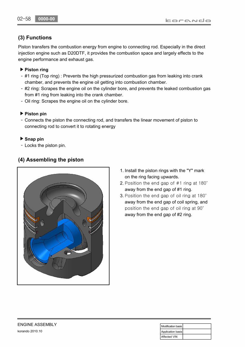
(3) FunctionsPiston transfers the combustion energy from engine to connecting rod. Especially in the direct injection engine such as D20DTF, it provides the combustion space and largely effects to the engine performance and exhaust gas.
Piston ring#1 ring (Top ring) : Prevents the high pressurized combustion gas from leaking into crank chamber, and prevents the engine oil getting into combustion chamber. #2 ring: Scrapes the engine oil on the cylinder bore, and prevents the leaked combustion gas from #1 ring from leaking into the crank chamber. Oil ring: Scrapes the engine oil on the cylinder bore.
Piston pinConnects the piston the connecting rod, and transfers the linear movement of piston to connecting rod to convert it to rotating energy
Snap pinLocks the piston pin.
▶
-
-
-
▶
-
▶
-
(4) Assembling the piston
Install the piston rings with the "Y" mark on the ring facing upwards.Position the end gap of #1 ring at 180˚
away from the end gap of #1 ring.Position the end gap of oil ring at 180˚
away from the end gap of coil spring, and position the end gap of oil ring at 90˚
away from the end gap of #2 ring.
1.
2.
3.

02-59
ENGINE ASSEMBLYkorando 2010.10
0000-00
2) Connecting Rod(1) OverviewConnecting rod converts the reciprocating movement of piston to the rotating movement of crankshaft. The big end is connected to connecting rod bearing and the crank pin journal, and the small end is connected to the piston pin.
(2) Components
Piston pin bush
Connecting rod
Connecting lower bearing
Connecting rod cap
Connecting rod cap bolt
Connecting rod upper bearing

02-60
korando 2010.10
0000-00
ENGINE ASSEMBLY
3) Crankshaft(1) Overview
Crankshaft is installed on the cylinder block. And, the ring gear for Mass Balance Unit is installed on it.
(2) Arrangement
Crankshaft main bearing upper Crankshaft main bearing upper
Upper thrust bearing
Crankshaft main bearing lower Crankshaft main bearing lower
Lower thrust bearing
Crank pin journal Main journal
MBU drive ring gear

02-61
ENGINE ASSEMBLYkorando 2010.10
0000-00
(3) Selection of crankshaft main bearingCombination between crankshaft upper bearing shell and crankcase basic bearing bore
Basic bearing bore mark on oil pan mounting surface
Color code of crankshaft bearing shell
Punch mark 1 or Blue mark Blue or White - Blue
Punch mark 2 or Blue mark Yellow or White - Yellow
Punch mark 3 or Blue mark Red or White - Red
Combination between crankshaft lower bearing shell and crankcase basic bearing journal
Basic bearing journal mark on crankcase
Color code of crankshaft bearing shell
Blue or White - Blue Blue or White - Blue
Yellow or White - Blue Yellow or White - Yellow
Red or White - Blue Red or White - Red
Selection of upper main bearing▶
Mark Identification color
* Blue
** Yellow
*** Red
Selection of lower main bearing▶
Mark Identification color
B Blue
R Red
V Violet
Y Yellow
W White
Select the lower main bearing for crankshaft bearing cap according to the mark on crankshaft front end.

02-62
korando 2010.10
0000-00
ENGINE ASSEMBLY
4) Cylinder Block(1) Overview
The major dimensions in D20DTF are similar to D20DT. It has two mounting bosses for knock sensor and meets the requirements for EURO5 regulation.
(2) Layout

02-63
ENGINE ASSEMBLYkorando 2010.10
0000-00
(3) Features
For simple manufacturing, the crankcase blowby gas passage and the oil return hole are made by casting on the cylinder block.
Crankcase ventilation

02-64
korando 2010.10
0000-00
ENGINE ASSEMBLY
The bottom side of water jacket is desgined as sine wave to strengthen the structure of crankcase. The main flow of coolant starts from outlet port of water pump and goes along the longitudinal direction of engine. The coolant passage from cylinder head to inlet port of water pump is integrated in cylinder head.
The engine oil from oil pump is supplied to the main oil gallery through oil channel, oil filter module and cross bore in cylinder block without using external pipes. This oil is supplied to main bearing, cylinder head and MBU. And, it is sprayed to the chain through the chain tensioner connected to cross bore.
Crankcase cross bore for oil supply
Water jacket core

02-65
ENGINE ASSEMBLYkorando 2010.10
1336-00
Cover - Timing caseSealing - Crankshaft FRTBoltTensioner assy - BeltBoltCover - Idler pulley
1.2.3.4.5.7.
Pulley assy - IdlerBoltBRKT - IdlerPulley assy - IdlerPlug assy - ScrewCover - Idler pulley
8.18.23.25.27.28.

02-66
korando 2010.10
1336-04
ENGINE ASSEMBLY
Disconnect the negative cable from the battery.Remove the engine acoustic cover.Remove the crankshaft main cover.
---
Remove the coolant reservoir (A).1.
Unscrew the mounting bolts (B) for the power steering oil tank (A).
2.
Disconnect the coolant hose (B).Unscrew the mounting bolts (C).
--
Put a floor jack under the engine oil pan.3.

02-67
ENGINE ASSEMBLYkorando 2010.10
1336-04
Remove the belt.6.
Raise the jack to clear the area.Turn the tension release bolt (B) of the belt tensioner assembly (A) (Pivot damped tensioner) clockwise using a special tool to release the tension of the belt tensioner before removing the belt.
--
Special tool: T9941 0010A
Remove the MTG bracket on the right side (A).
4.
Unscrew the engine insulator mounting nut (B), engine mounting bracket nut (C) and bolts (D).
-
Remove the MTG on the right side (A).5.
Unscrew the bolts (B) and the nut (C).-

02-68
korando 2010.10
1336-04
ENGINE ASSEMBLY
Remove the idler pulley cover (A) and remove the idler pulley cover No. 2 (B).
7.
Unscrew the bolts (B) and the nut (C).8.
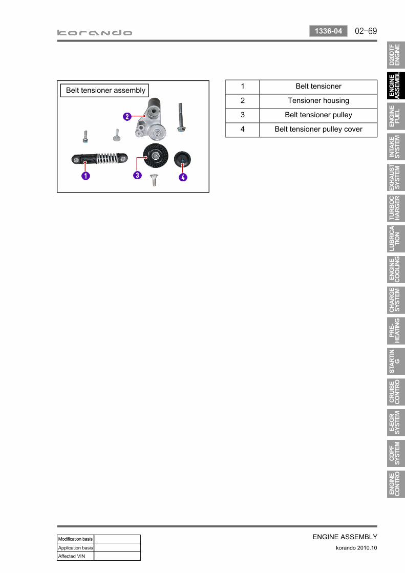
Remove the belt tensioner assembly (A).9.
Install in the reverse order of removal.10.
02-69
ENGINE ASSEMBLYkorando 2010.10
1336-04
1 Belt tensioner
2 Tensioner housing
3 Belt tensioner pulley
4 Belt tensioner pulley cover
Belt tensioner assembly

02-70
korando 2010.10
1336-25
ENGINE ASSEMBLY
Disconnect the negative cable from the battery.Remove the engine acoustic cover.Remove the crankshaft main cover.Install a portable jack under the engine.
----
Remove the engine mounting insulator bracket (A) on the right-hand side.
1.
For more information, refer to the section "Engine Mountings" of Chapter "Engine Assembly".
Release the tension of the belt tensioner assembly (Pivot damped tensioner) and remove the belt.
2.
For more information, refer to the section "Belt Tensioner Assembly" of Chapter "Engine Assembly".
Idler pulley assembly No. 2
Idler pulley assembly No. 1 1 Idler pulley cover No. 1
2 Idler pulley No. 1
3 Idler pulley No. 1 mounting bolt
4 Idler pulley cover No. 2
5 Idler pulley No. 2
6 Idler pulley No. 2 mounting bolt
REMOVAL AND INSTALLATION
02-71
ENGINE ASSEMBLYkorando 2010.10
1336-25
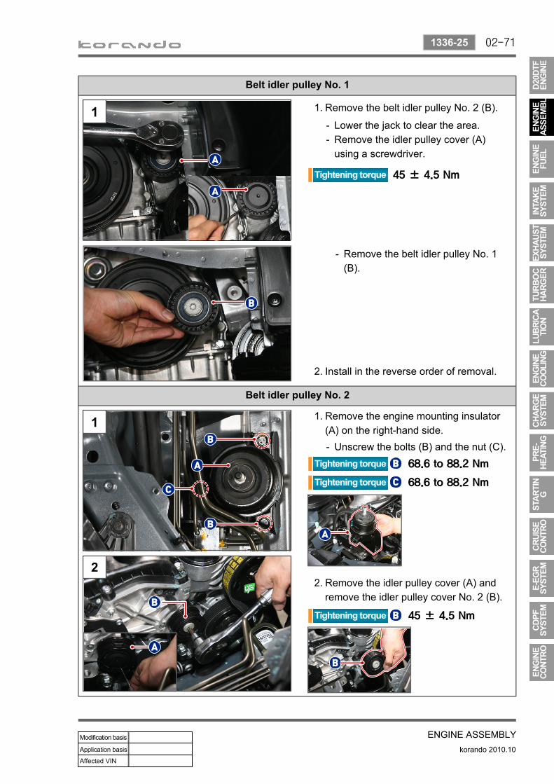
Belt idler pulley No. 1
Belt idler pulley No. 2
Remove the engine mounting insulator (A) on the right-hand side.
1.
Unscrew the bolts (B) and the nut (C).-
Remove the idler pulley cover (A) and remove the idler pulley cover No. 2 (B).
2.
Remove the belt idler pulley No. 2 (B).1.
Lower the jack to clear the area.Remove the idler pulley cover (A) using a screwdriver.
--
Remove the belt idler pulley No. 1 (B).
-
Install in the reverse order of removal.2.

02-72
korando 2010.10
1130-00
ENGINE ASSEMBLY
CrankshaftKey - Crankshaft pulleySprocket - CrankshaftDisc - Crankshaft vibration damperBoltDamper assembly - Isolation
1.3.4.7.8.
12.

02-73
ENGINE ASSEMBLYkorando 2010.10
1130-12
Disconnect the negative cable from the battery.Remove the engine acoustic cover.Remove the engine under cover.Remove the crankshaft main cover.
----
Install an engine support hanger to the engine hanger.
3.
Remove the coolant reservoir (A).1.
Unscrew the mounting bolts (B) for the power steering oil tank (A).
2.
Disconnect the coolant hose (B).Unscrew the mounting bolts (C).
--

02-74
korando 2010.10
1130-12
ENGINE ASSEMBLY
Remove the starter.7.
Disconnect the ST connector (B) of the starter while the vehicle is lifted up.Disconnect the B -terminal (C) of the starter. Unscrew the bolt (D).
-
-
-
For more details, refer to the section "Starter" of "Starting System".
Remove the front engine mounting insulator (A).
5.
For more information, refer to the section "Engine Mountings" of Chapter "Engine Assembly".
-
Remove the front engine mounting insulator bracket (A).
6
Remove the MTG bracket on the right side (A).
4.
Unscrew the engine insulator mounting nut (B), engine mounting bracket nut (C) and bolts (D).
-

02-75
ENGINE ASSEMBLYkorando 2010.10
1130-12
Unscrew the crankshaft center bolt using a special tool.
10.
Remove the isolation damper (A). 11.
Install in the reverse order of removal.12.
Special tool for crankshaft pulley center boltP/N : 000 000 00 00
-
Lower the engine support hanger (A) making sure not to interfere with the surrounding parts.
8.
Fit the flywheel assembly using a special tool (000 000 00 00).
9.
For more details, refer to the section "Starter" of Chapter "Starting System".

02-76
korando 2010.10
1130-12
ENGINE ASSEMBLY
Tightening process for crankshaft center bolt
Torque wrench200 ± 20 Nm
Put matchmark Tighten - 1st90°±10°
Tighten - 2nd90°±10°
Removal of crankshaft front seal-ring (A)
Remove the crankshaft front seal-ring, making sure that the mounting groove of the seal-ring and the crankshaft are not damaged with a screwdriver wrapped with clean cloth.
Installation of crankshaft front seal-ring (A)
Mount the crankshaft front seal-ring (A) to the TGCC and install it with a special tool (B).

02-77
ENGINE ASSEMBLYkorando 2010.10
1610-00
Pump assembly - VacuumBolt
1.3.

02-78
korando 2010.10
1610-01
ENGINE ASSEMBLY
Disconnect the negative cable from the battery.Remove the engine acoustic cover.Remove the engine under cover.
---
Remove the coolant reservoir (A).1.Disconnect the coolant hose (B).Unscrew the mounting bolts (C).
--
Unscrew the mounting bolts (A) for the power steering oil tank.
2.
Put a floor jack under the engine oil pan.3.
Put a floor jack under the engine before removing the engine mountings (RH, MTG) to clear the space.
02-79
ENGINE ASSEMBLYkorando 2010.10
1610-01
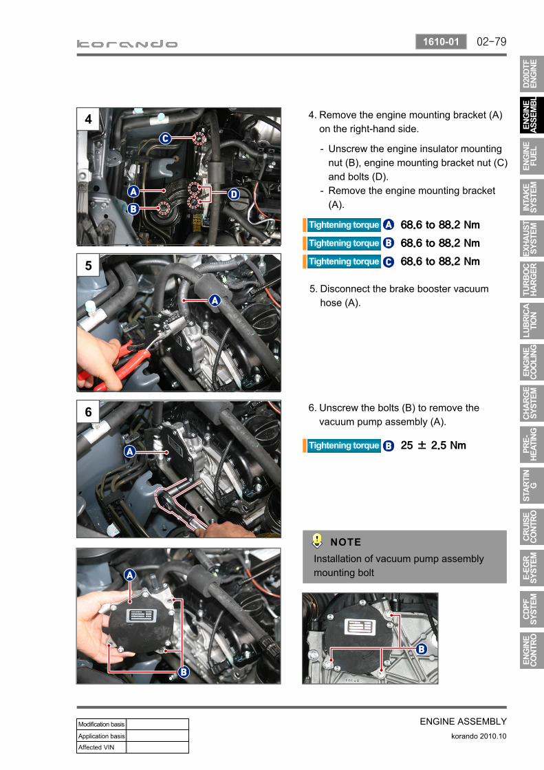
Remove the engine mounting bracket (A) on the right-hand side.
4.
Unscrew the engine insulator mounting nut (B), engine mounting bracket nut (C) and bolts (D).Remove the engine mounting bracket (A).
-
-
Disconnect the brake booster vacuum hose (A).
5.
Unscrew the bolts (B) to remove the vacuum pump assembly (A).
6.
Installation of vacuum pump assembly mounting bolt

02-80
korando 2010.10
1610-01
ENGINE ASSEMBLY
Cautions on installing vacuum pump
Replace the sealing (A and B) of the vacuum pump with new ones.Apply oil to the sealing before installing it, and check the installation status after installing.
-
-
Setting the correct timing makes the exhaust camshaft line up as shown in the figure (A-A').When installing the vacuum pump, make sure that it is lined up as shown in the figure (B-B').
-
-B B’

02-81
ENGINE ASSEMBLYkorando 2010.10
1990-00
Insulator - Engine MTGInsulator - Engine MTGInsulator - Engine MTG FRTBoltBoltBolt - BRKT MTG
1.2.3.4.5.6.
BRKT - ENGINE MTGNut - Hex flg_M12x1.25Insulator - Engine MTG RRBoltNutBoltBolt
8.10.11.12.13.14.15.

02-82
korando 2010.10
1330-01
ENGINE ASSEMBLY
Disconnect the negative cable from the battery.Remove the engine acoustic cover.Remove the engine under cover.
---
Disconnect the air duct hose (A).1.
Disengage the mounting clamp (B).Remove the intake air inlet duct side (C) of the oil separator.Disconnect the HFM connector (D).Disengage the air cleaner assembly mounting clips (E).
--
--
Remove the ECU/GCU (preheating control unit) and bracket.
2.
Disconnect the ECU connector (A).Unscrew the bolts (B).
--
Disconnect the GCU (preheating control unit) connectors (A and B), and remove the ECU assembly.
3.ECU
GCUThe GCU connector (B) has locking parts on both sides.

02-83
ENGINE ASSEMBLYkorando 2010.10
1330-01
Unscrew the clamp mounting bolts (A) to remove the battery.
4.
Remove the bracket at the bottom of the battery (A).
5.
Unlock the connector holders (B).Unscrew the bolts (C).Unscrew the bolt (D).
---
Put a floor jack under the transmission.6.
Remove the through bolt installed to the engine mounting bracket.
7.

02-84
korando 2010.10
1330-01
ENGINE ASSEMBLY
Unscrew the mounting bolts (B) to remove the MTG (A, LH).
8.
Engine mounting insulator (LH-MTG)Engine mounting insulator (LH)
Engine mounting insulator (LH)

02-85
ENGINE ASSEMBLYkorando 2010.10
1990-02
Disconnect the negative cable from the battery.Remove the engine acoustic cover.Remove the engine under cover.
---
Remove the coolant reservoir (A).1.Disconnect the coolant hose (B).Unscrew the mounting bolts (C).
--
Unscrew the mounting bolts (B) for the power steering oil tank (A).
2.
Put a floor jack under the engine oil pan.3.
02-86
korando 2010.10
1990-02
ENGINE ASSEMBLY
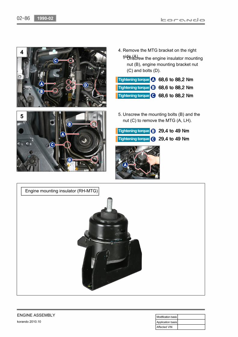
Remove the MTG bracket on the right side (A).
4.
Unscrew the engine insulator mounting nut (B), engine mounting bracket nut (C) and bolts (D).
-
Unscrew the mounting bolts (B) and the nut (C) to remove the MTG (A, LH).
5.
Engine mounting insulator (RH-MTG)

02-87
ENGINE ASSEMBLYkorando 2010.10
1990-03
Disconnect the negative cable from the battery.Remove the engine acoustic cover.Remove the engine under cover.
---
Put a transmission jack under the vehicle.1.
Remove the through bolt installed to the MTG (A, FR).
2.
FRT-MTG (Manual Transmission) FRT-MTG (Automatic Transmission)
The appearance of the front engine mounting insulator is different from each other for the automatic/manual transmissions. But the basic procedures are the same for both transmissions.The description stated here is for the manual transmission.

02-88
korando 2010.10
1990-03
ENGINE ASSEMBLY
Unscrew the mounting nut (A) on the engine mounting insulator to remove the MTG (B, FR).
4.
Unscrew the mounting bolt (A) on the engine mounting insulator.
3.
FRT-MTG (Manual Transmission) FRT-MTG (Automatic Transmission)

02-89
ENGINE ASSEMBLYkorando 2010.10
1990-11
Disconnect the negative cable from the battery.Remove the engine acoustic cover.Remove the engine under cover.
---
Put a transmission jack under the vehicle.1.
Remove the through bolt installed to the rear engine mounting insulator.
2.
Unscrew the mounting bolt (A) on the rear engine mounting insulator.
3.

02-90
korando 2010.10
1990-11
ENGINE ASSEMBLY
Rear engine mounting insulator

02-91
ENGINE ASSEMBLYkorando 2010.10
1225-00
Cover - Cylinder headGasket - Cylinder head coverBoltCap assy - Oil fillerHose assy - Blow by outlet
1.2.3.4.
14.
ClampCamshaft assy - IntakeCamshaft assy - ExhaustPin - CylindricalCover - Cylinder headBolt
16.21.22.23.24.25.

02-92
korando 2010.10
1225-01
ENGINE ASSEMBLY
Disconnect the negative cable from the battery.Remove the engine acoustic cover.
--
Remove the hose assembly (Air cleaner to Turbocharger) (A).
1.
Disengage the mounting clamp (B).Remove the intake air inlet duct side (C) of the oil separator.Disconnect the HFM connector (D).
--
-
Disconnect the booster vacuum hose (A) and EGR bypass vacuum hose (B).
2.
Remove the high pressure pipe.3.
From HP pump to Common rail (A)From Common rail to Injector (B)
--
Replace the fuel supply pipe with a new one.The openings of the common rail and the injector should be sealed with the sealing caps.
-
-

02-93
ENGINE ASSEMBLYkorando 2010.10
1225-01
Connectors that should be removed before removing main wiring
Pre-heating plug Connector
Variable swirl valve
Fuel rail pressure sensor
Front EGT sensor
Injector connector
Cam position sensor
Rear EGT sensor
Wide band oxygen sensor
Remove the engine main wiring (A).4.
Unlock the wiring mounting holder (B).Unscrew the bolts (C).Disconnect the main wiring connector on the upper side of the cylinder head cover.
---
02-94
korando 2010.10
1225-01
ENGINE ASSEMBLY
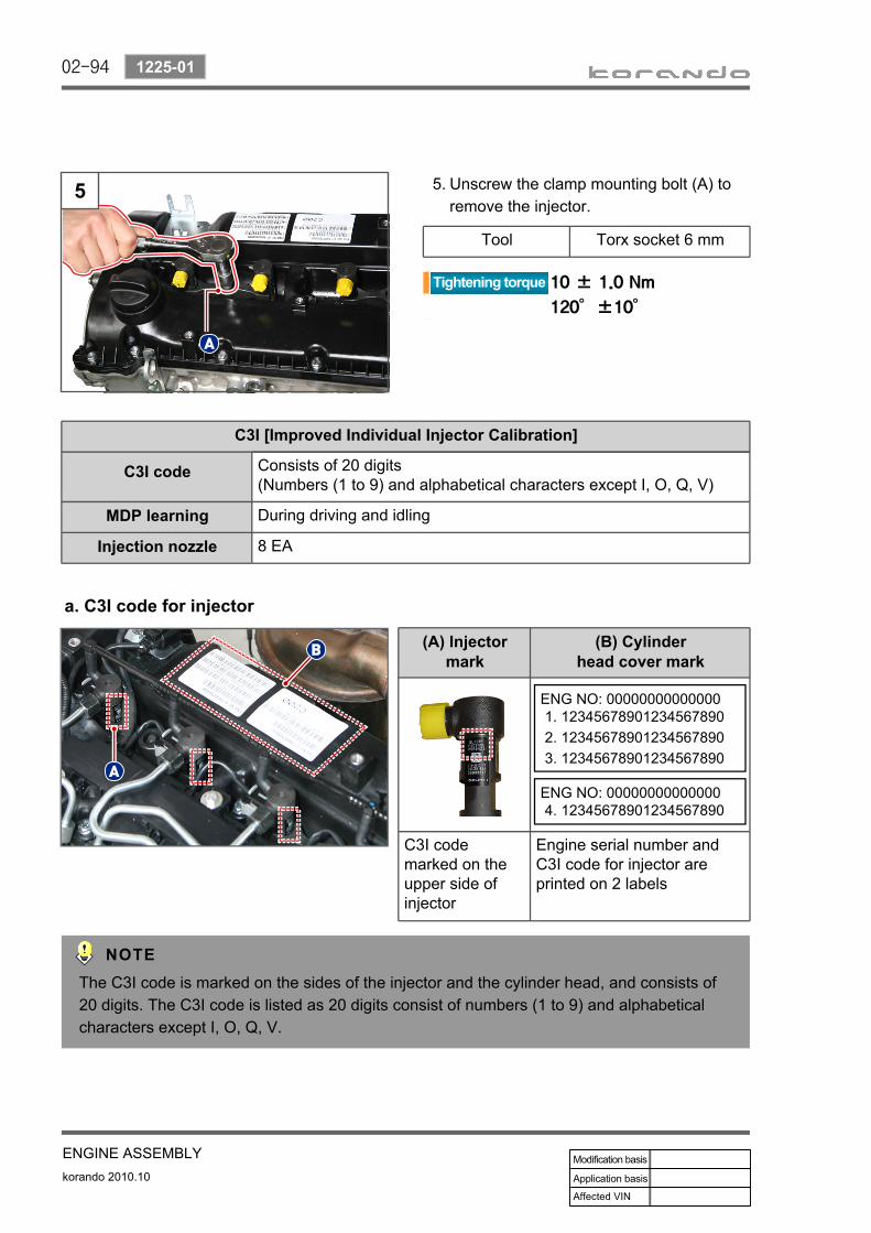
Unscrew the clamp mounting bolt (A) to remove the injector.
5.
Tool Torx socket 6 mm
a. C3I code for injector
The C3I code is marked on the sides of the injector and the cylinder head, and consists of 20 digits. The C3I code is listed as 20 digits consist of numbers (1 to 9) and alphabetical characters except I, O, Q, V.
ENG NO: 000000000000001. 123456789012345678902. 123456789012345678903. 12345678901234567890
ENG NO: 000000000000004. 12345678901234567890
C3I [Improved Individual Injector Calibration]
C3I code Consists of 20 digits(Numbers (1 to 9) and alphabetical characters except I, O, Q, V)
MDP learning During driving and idling
Injection nozzle 8 EA
(A) Injectormark
(B) Cylinderhead cover mark
C3I code marked on the upper side of injector
Engine serial number and C3I code for injector are printed on 2 labels

02-95
ENGINE ASSEMBLYkorando 2010.10
1225-01
Remove the cylinder head cover (A).6.Unscrew the bolts for the cylinder head cover slowly in two or more stages to prevent any damage to the cylinder head.Removal: from the outside to the inside, diagonallyInstallation: From the center to the outside, diagonally
-
-
-
Install in the reverse order of removal.7.
Cylinder head cover
Cylinder head cover gasket
Replace the cylinder head cover gasket with a new one.
02-96
korando 2010.10
1214-00
ENGINE ASSEMBLY
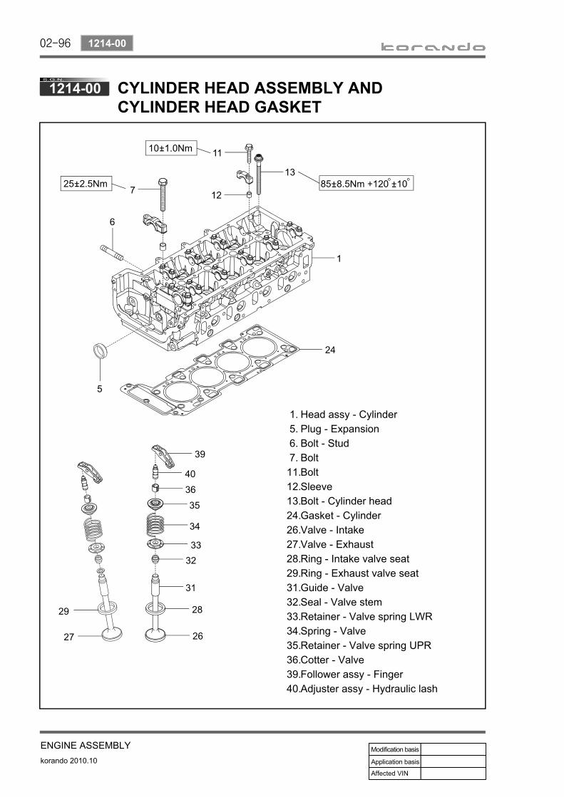
Head assy - CylinderPlug - ExpansionBolt - StudBoltBoltSleeveBolt - Cylinder headGasket - CylinderValve - IntakeValve - ExhaustRing - Intake valve seatRing - Exhaust valve seatGuide - ValveSeal - Valve stemRetainer - Valve spring LWRSpring - ValveRetainer - Valve spring UPRCotter - ValveFollower assy - FingerAdjuster assy - Hydraulic lash
1.5.6.7.
11.12.13.24.26.27.28.29.31.32.33.34.35.36.39.40.
CYLINDER HEAD GASKET

02-97
ENGINE ASSEMBLYkorando 2010.10
1214-01
Disconnect the negative cable from the battery.Remove the engine acoustic cover.Remove the engine under cover.Remove the crankshaft main cover.
----
Align the timing of the crankshaft and the camshaft.
1.
Do not reverse the engine.
Turn the isolation damper (A) so that the timing mark (B) on the isolation damper and the mark (C) on the timing gear case cover are aligned.
-
Open the oil filler cap and check the camshaft nose position (A) of the intake camshaft.(If the camshaft nose position is incorrect, then turn the crankshaft 1 revolution and align the camshaft nose to 12 o'clock.)
-
TDC mark
Isolation damper mark
Timing caseCover mark
How to check timing position
The timing mark is located on the position where the no. 1 cylinder piston is rotated further 90 degrees clockwise from the TDC (D) point.
02-98
korando 2010.10
1214-01
ENGINE ASSEMBLY
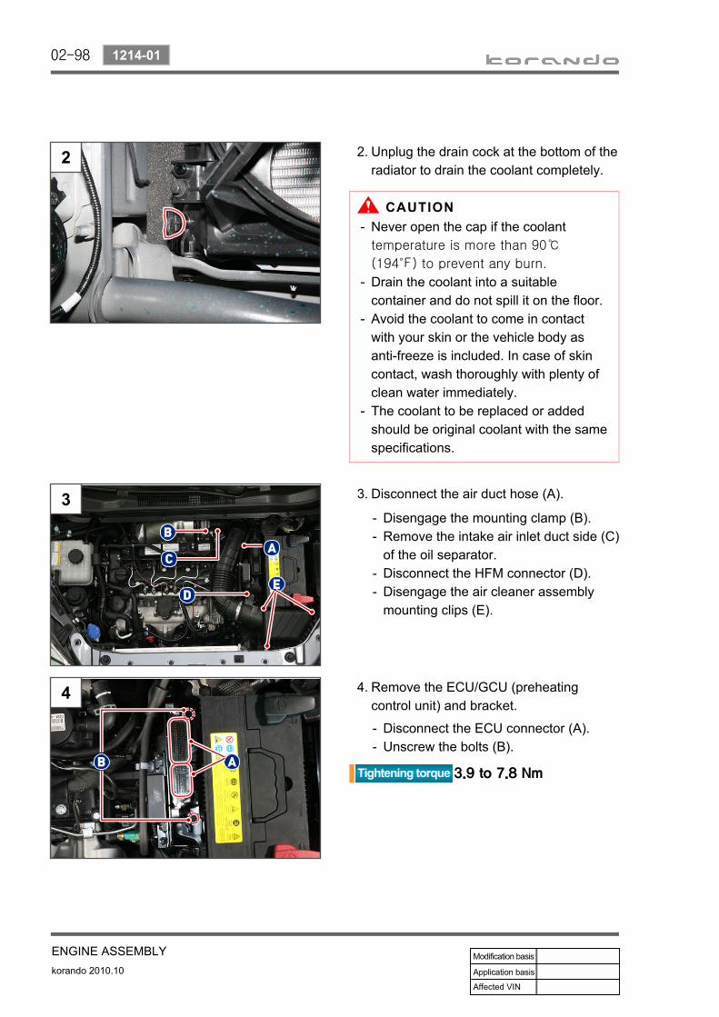
Unplug the drain cock at the bottom of the radiator to drain the coolant completely.
2.
Disconnect the air duct hose (A).3.
Disengage the mounting clamp (B).Remove the intake air inlet duct side (C) of the oil separator.Disconnect the HFM connector (D).Disengage the air cleaner assembly mounting clips (E).
--
--
Remove the ECU/GCU (preheating control unit) and bracket.
4.
Disconnect the ECU connector (A).Unscrew the bolts (B).
--
Never open the cap if the coolant temperature is more than 90℃
(194℉) to prevent any burn.
Drain the coolant into a suitable container and do not spill it on the floor. Avoid the coolant to come in contact with your skin or the vehicle body as anti-freeze is included. In case of skin contact, wash thoroughly with plenty of clean water immediately.The coolant to be replaced or added should be original coolant with the same specifications.
-
-
-
-

02-99
ENGINE ASSEMBLYkorando 2010.10
1214-01
Disconnect the GCU (preheating control unit) connectors (A and B), and remove the ECU assembly.
5.ECU
GCU
Unscrew the clamp mounting bolts (A) to remove the battery.
6.
Remove the bracket at the bottom of the battery (A).
7.
Unlock the connector holders (B).Unscrew the bolts (C).Unscrew the bolt (D).
---
Remove the duct and hose assembly (Turbocharger to Intercooler) (A).
8.
Disengage the hose clamps on the turbocharger (A) and intercooler (B).Unscrew the mounting nut for duct (C).
-
-
The GCU connector (B) has locking parts on both sides.

02-100
korando 2010.10
1214-01
ENGINE ASSEMBLY
Remove the high pressure pump (A).9.
Remove the CDPF assembly (A).10.
Make sure not to damage the rear exhaust gas temperature sensor when removing it.
Remove the VGT (A).11.
Remove the EGR pipe (A), intake duct (B) and electric throttle body (C).
12.
For more information about the high pressure pump, see the section "Fuel Supply System".
For more information about the CDPF, refer to the section "CDPF".
For more information about E-VGT, refer to the section "Turbocharger".
For more information about E-EGR, refer to the section "EGR System".
02-101
ENGINE ASSEMBLYkorando 2010.10
1214-01
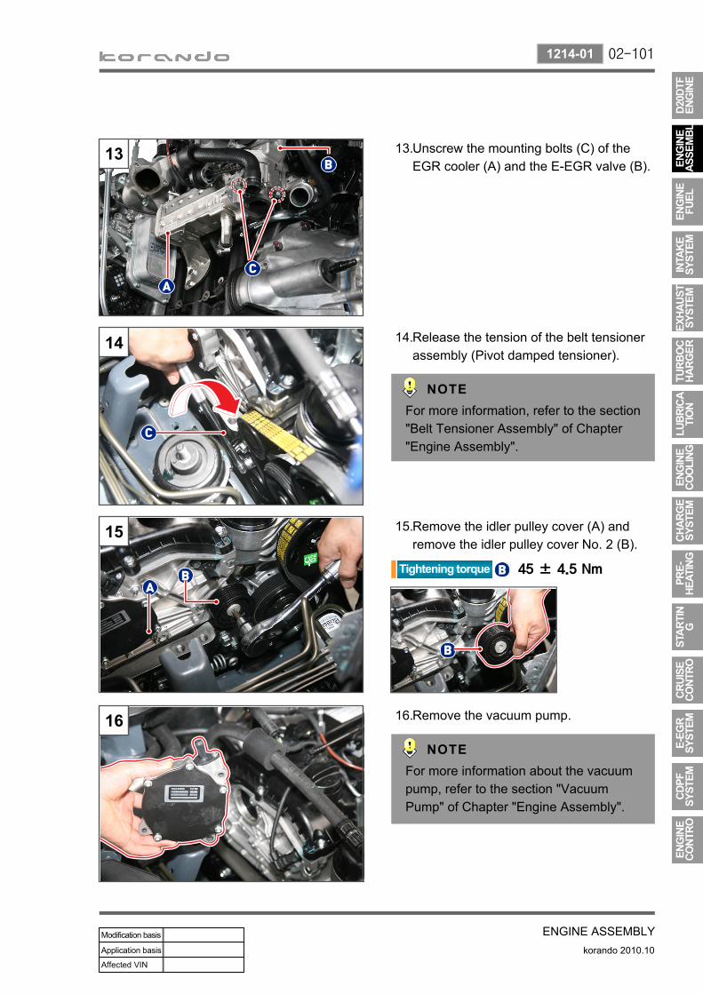
Unscrew the mounting bolts (C) of the EGR cooler (A) and the E-EGR valve (B).
13.
Release the tension of the belt tensioner assembly (Pivot damped tensioner).
14.
For more information, refer to the section "Belt Tensioner Assembly" of Chapter "Engine Assembly".
Remove the idler pulley cover (A) and remove the idler pulley cover No. 2 (B).
15.
Remove the vacuum pump. 16.
For more information about the vacuum pump, refer to the section "Vacuum Pump" of Chapter "Engine Assembly".
02-102
korando 2010.10
1214-01
ENGINE ASSEMBLY
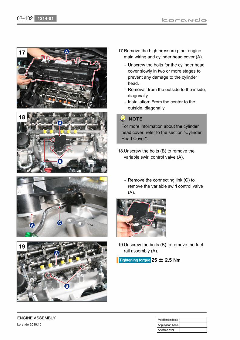
Remove the high pressure pipe, engine main wiring and cylinder head cover (A).
17.
Unscrew the bolts for the cylinder head cover slowly in two or more stages to prevent any damage to the cylinder head.Removal: from the outside to the inside, diagonallyInstallation: From the center to the outside, diagonally
-
-
-
For more information about the cylinder head cover, refer to the section "Cylinder Head Cover".
Unscrew the bolts (B) to remove the variable swirl control valve (A).
18.
Remove the connecting link (C) to remove the variable swirl control valve (A).
-
Unscrew the bolts (B) to remove the fuel rail assembly (A).
19.

02-103
ENGINE ASSEMBLYkorando 2010.10
1214-01
Remove the glow plug (A).20.
Remove the screw plug (A) and release the tension of the hydraulic chain tensioner.
21.
Put a jack under the engine before removing the engine mounting (RH, MTG) to clear the space.
Compress the chain tensioner with a flat-bladed screwdriver.
-
Compress the hydraulic chain tensioner (A) using a flat-bladed screwdriver and insert the mounting pin (B) to secure the tensioner.
-
Hydraulic chain tensioner
The contact surface of the cylinder block and the cylinder head is lower than the heater of the glow plug. So the glow plug must be removed.
Use a piece of cloth not to damage the plug threads.

02-104
korando 2010.10
1214-01
ENGINE ASSEMBLY
Secure the timing chain to the part (B) as shown in the figure to prevent the timing chain from falling into the cylinder block.
23.
Tie the timing chain to the clamping rail (C) as shown in the figure.
-
Remove the cylinder head front cover (A).
22.
Do not apply excessive force to remove it. Otherwise, chips or foreign materials can enter into the engine.
Position to pry out front cover
Tie the chain tightly so as not to fall into the timing gear case.

02-105
ENGINE ASSEMBLYkorando 2010.10
1214-01
Secure the spanner seat (A) of the intake camshaft with a 30 mm spanner, and unscrew the exhaust camshaft sprocket bolts (B) to remove the sprocket.
24.
Exhaust camshaft sprocket
Cautions for installation▶
Pull up the timing chain provided that the timing chain is not tilted, so that the chain is aligned to the tensioner rail (A) and the clamping rail (B).
1.
Install the camshaft sprocket by aligning the exhaust camshaft sprocket mark (C) to the marking link (copper link) (D) of the timing chain.
2.
Fit the exhaust camshaft sprocket (C) to the camshaft (E) and tighten the mounting bolts to the specified torque.
3.
Check the alignment of the timing chain and the clamping/tensioner rails again when installing the camshaft.

02-106
korando 2010.10
1214-01
ENGINE ASSEMBLY
Unscrew the camshaft bearing cap bolts (A).26.
Unscrew the camshaft mounting bolts slowly in two or more stages according to the specific sequence stated below.(1) Intake camshaft: IN, 6, 8(2) Exhaust camshaft: EX, 2, 4(3) Intake camshaft: 5, 7, 9(4) Exhaust camshaft: 1, 3
-
Tightening torque
EX, IN bearing cap 25 ± 2.5 Nm
No. 1 to 9 bearing caps 10 ± 1.0 Nm
Always tighten to the specified torque so as not to damage the camshaft.
Unscrew the mounting bolt (B) to remove the tensioner rail (A).
25.
Arrange the timing chain (C) as shown in the figure to minimize any interference when removing the tensioner rail.

02-107
ENGINE ASSEMBLYkorando 2010.10
1214-01
Timing marks on intake and exhaust camshafts
Align the two timing marks on the intake camshaft gear (A) to the one timing mark on the exhaust camshaft gear (B).
The timing marks are on both sides of the intake and exhaust camshaft gears.
Align the timing marks on the intake/exhaust camshaft sprockets.
Remove the intake/exhaust camshafts.27.
Exhaust camshaft: Intake camshaft:
Remove the camshaft and no. 1 lower cap (A).
28.

02-108
korando 2010.10
1214-01
ENGINE ASSEMBLY
Unscrew the cylinder head shoulder bolts (A, T6 mm).
30.
Unscrew the cylinder head bolt (A). 31.
Unscrew the cylinder head bolts in two or more stages according to the specific sequence.
-
Replace the mounting bolt if it is extended by 0.9 mm or more.
Tighten the bolts in the reverse order of removal in 2 or 3 steps with the specified torque.
Remove the finger follow and HLA device (A).
29.
Take extreme care because the HLA device is very hot right after the engine is turned off.If the removed finger follower and HLA device is easily pressed, it means that the oil has been drained. In this case, replace it with a new one.
-
-
Apply engine oil before installing.
02-109
ENGINE ASSEMBLYkorando 2010.10
1214-01
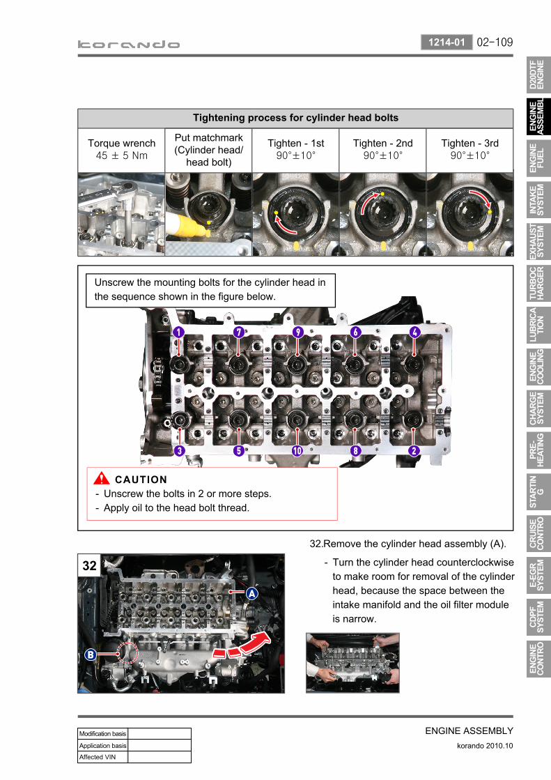
Tightening process for cylinder head bolts
Torque wrench45 ± 5 Nm
Put matchmark(Cylinder head/
head bolt)
Tighten - 1st90°±10°
Tighten - 2nd90°±10°
Tighten - 3rd90°±10°
Unscrew the bolts in 2 or more steps.Apply oil to the head bolt thread.
--
Remove the cylinder head assembly (A). 32.
Turn the cylinder head counterclockwise to make room for removal of the cylinder head, because the space between the intake manifold and the oil filter module is narrow.
-
Unscrew the mounting bolts for the cylinder head in the sequence shown in the figure below.

02-110
korando 2010.10
1214-01
ENGINE ASSEMBLY
Remove the cylinder head gasket (A).33.
Before assembling the cylinder head gasket, apply sealant to the contact surface (C) where the cylinder block (A) and the timing gear case cover (B) meet.
34.
Remove the E-EGR valve (A), intake manifold (B) and exhaust manifold (C) from the removed cylinder head.
35.
Cylinder head assembly
02-111
ENGINE ASSEMBLYkorando 2010.10
1214-01
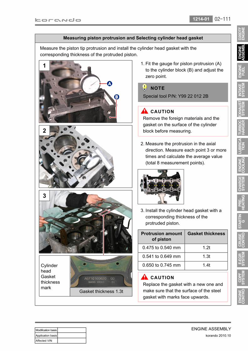
Measuring piston protrusion and Selecting cylinder head gasket
Measure the piston tip protrusion and install the cylinder head gasket with the corresponding thickness of the protruded piston.
Fit the gauge for piston protrusion (A) to the cylinder block (B) and adjust the zero point.
1.
Special tool P/N: Y99 22 012 2B
Measure the protrusion in the axial direction. Measure each point 3 or more times and calculate the average value (total 8 measurement points).
2.
Install the cylinder head gasket with a corresponding thickness of the protruded piston.
3.
Protrusion amount of piston
Gasket thickness
0.475 to 0.540 mm 1.2t
0.541 to 0.649 mm 1.3t
0.650 to 0.745 mm 1.4t
Remove the foreign materials and the gasket on the surface of the cylinder block before measuring.
Replace the gasket with a new one and make sure that the surface of the steel gasket with marks face upwards.
Cylinder head Gasket thickness mark
Gasket thickness 1.3t
02-112
korando 2010.10
0000-00
ENGINE ASSEMBLY
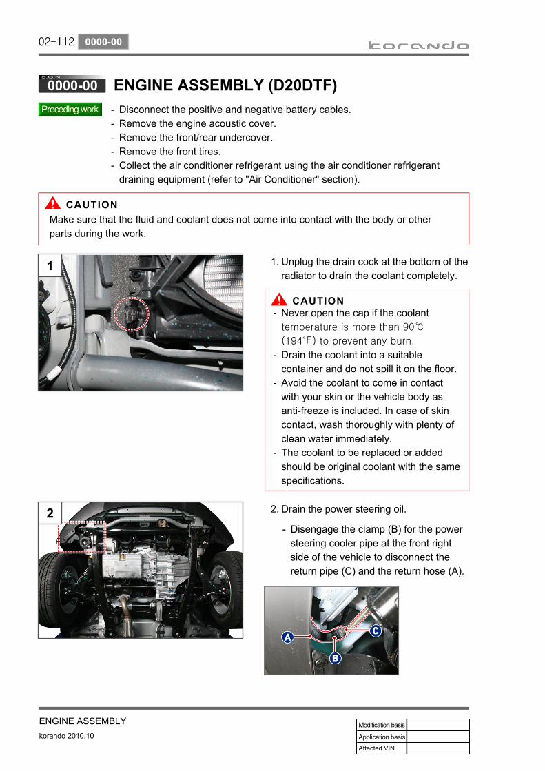
Disconnect the positive and negative battery cables.Remove the engine acoustic cover.Remove the front/rear undercover.Remove the front tires.Collect the air conditioner refrigerant using the air conditioner refrigerant draining equipment (refer to "Air Conditioner" section).
-----
Unplug the drain cock at the bottom of the radiator to drain the coolant completely.
1.
Never open the cap if the coolant temperature is more than 90℃
(194℉) to prevent any burn.
Drain the coolant into a suitable container and do not spill it on the floor. Avoid the coolant to come in contact with your skin or the vehicle body as anti-freeze is included. In case of skin contact, wash thoroughly with plenty of clean water immediately.The coolant to be replaced or added should be original coolant with the same specifications.
-
-
-
-
Drain the power steering oil.2.
Disengage the clamp (B) for the power steering cooler pipe at the front right side of the vehicle to disconnect the return pipe (C) and the return hose (A).
-
Make sure that the fluid and coolant does not come into contact with the body or other parts during the work.

02-113
ENGINE ASSEMBLYkorando 2010.10
0000-00
Remove the coolant reservoir (A).3.
Disconnect the coolant return hoses (B) and supply hose (C).Unscrew the mounting bolts (D).
-
-
Be careful so that the residual coolant in the coolant reservoir does not leak.
Disconnect the power steering oil supply hose.
4.
Disengage the clamp (A).Unscrew the hollow bolt (B) securing the oil supply pipe.Disconnect the hose from the power steering pump.
--
-
Disconnect the air duct hose (A).5.
Disengage the mounting clamp (B).Remove the intake air inlet duct side (C) of the oil separator.Disconnect the HFM connector (D).Disengage the air cleaner assembly mounting clips (E).
--
--
Disconnect the connectors (A) and (B) to remove the ECU/GCU.
6.
Be careful not to bend the pin or let foreign material enter between the pins when connecting the engine ECU connectors.
02-114
korando 2010.10
0000-00
ENGINE ASSEMBLY
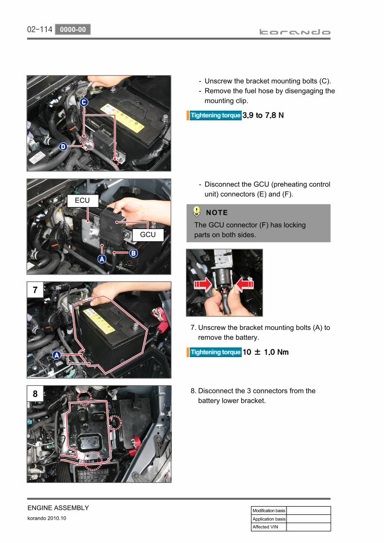
Unscrew the bracket mounting bolts (C).Remove the fuel hose by disengaging the mounting clip.
--
Disconnect the GCU (preheating control unit) connectors (E) and (F).
-
The GCU connector (F) has locking parts on both sides.
Unscrew the bracket mounting bolts (A) to remove the battery.
7.
Disconnect the 3 connectors from the battery lower bracket.
8.
ECU
GCU

02-115
ENGINE ASSEMBLYkorando 2010.10
0000-00
Remove the battery lower bracket. 9.Unscrew the bolts (A).Unscrew the bolt (B).
--
Disconnect the differential pressure sensor connector (A) and disengage the CDPF pressure hose clamps (B).
10.
Before disconnecting the pressure hoses, put matchmarks on each hose so as not to mix up the front and rear hoses.
Remove the fuel hoses and brake vacuum hose connected to the fuel filter.
11.
Disconnect fuel supply pipe (A). Disconnect fuel return pipe (B).
--
Disconnect the return hose (B) and drain the residual fuel to a suitable container.Be careful so that the residual fuel in the fuel hose does not leak out when disconnecting the fuel hose. In case of skin or vehicle body contact, wipe it out thoroughly with a piece of clean cloth.
-
-
Disconnect return pipe quick connector (C) from the injector nozzle side.Disconnect the brake vacuum hose (D).
-
-

02-116
korando 2010.10
0000-00
ENGINE ASSEMBLY
Disconnect the intercooler hose and pipe. 12.
a. Disengage the clamp on the turbocharger hose to disconnect the hose using a pair of clamp pliers.
b. Disengage the clamp on the intercooler hose to disconnect the hose using a pair of clamp pliers.
c. Unscrew the mounting bolt (A) to remove it.
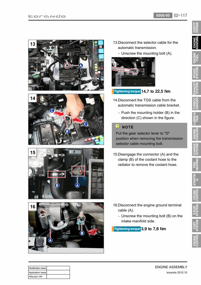
02-117
ENGINE ASSEMBLYkorando 2010.10
0000-00
Disconnect the selector cable for the automatic transmission.
13.
Unscrew the mounting bolt (A).-
Disconnect the TGS cable from the automatic transmission cable bracket.
14.
Push the mounting holder (B) in the direction (C) shown in the figure.
-
Put the gear selector lever to "D" position when removing the transmission selector cable mounting bolt.
Disengage the connector (A) and the clamp (B) of the coolant hose to the radiator to remove the coolant hose.
15.
Disconnect the engine ground terminal cable (A).
16.
Unscrew the mounting bolt (B) on the intake manifold side.
-

02-118
korando 2010.10
0000-00
ENGINE ASSEMBLY
Slacken the steering column shaft.17.
Unscrew the joint bolt (A).Slacken the steering column lower shaft (B) by pushing it in the direction (C).
--
Put align mark (A) before removing the lower shaft and the gear linkage while the steering wheel is in neutral position.
Remove the oil cooler pipes of automatic transmission.
18.
Confirm that no transmission fluid contacts to other objects.
Disconnect the intercooler hose (A) from the bottom of the vehicle after unscrewing the screw of the intercooler lower hose.
19.
Unscrew the nut (B) and disconnect the pipe (A) from the A/C compressor.
20.

02-119
ENGINE ASSEMBLYkorando 2010.10
0000-00
Remove the propeller shaft from the vehicle.21.
Disconnect No. 1 exhaust pipe (A).22.Unscrew the mounting nut (B) securing the No. 1 exhaust pipe and the CDPF.Unscrew the mounting nut (C) connecting the No. 1 exhaust pipe and the No. 1 exhaust pipe.Remove the No. 1 exhaust pipe from the mounting hanger (D).
-
-
-
Replace the front and rear gaskets with new ones when installing.
For further information, refer to the section "Propeller Shaft" of Chapter "Chassis".
21
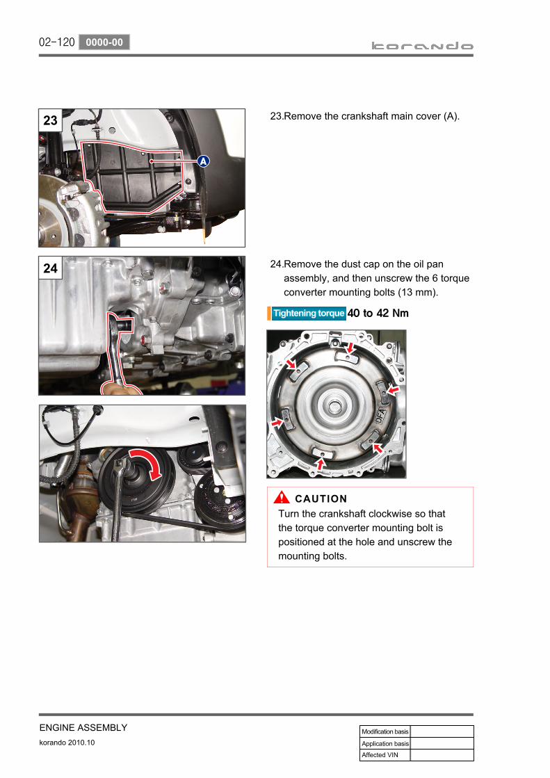
02-120
korando 2010.10
0000-00
ENGINE ASSEMBLY
Remove the crankshaft main cover (A).23.
Remove the dust cap on the oil pan assembly, and then unscrew the 6 torque converter mounting bolts (13 mm).
24.
Turn the crankshaft clockwise so that the torque converter mounting bolt is positioned at the hole and unscrew the mounting bolts.

02-121
ENGINE ASSEMBLYkorando 2010.10
0000-00
Unscrew the stabilizer bar front link upper nut (17 mm).
25.
Separate the steering tie rod end and knuckle arm.
26.
Remove the split pin (A) from the tie rod end.Unscrew the slot nut (17 mm).Remove the tie rod end from the knuckle arm using a special tool (B).
-
--
Replace the split pin with a new one.
Undo caulking of the hub nut (30 mm) and remove the hub nut (A).
27.
Replace the hub nut with a new one and caulk the upper part of the hub nut when installing.
Separate the lower arm and knuckle arm.28.Remove the split pin from the ball joint of the lower arm.Unscrew the slot nut (24 mm).Remove the lower arm ball joint from the knuckle arm using a special tool (B).
-
--
Replace the split pin with a new one.

02-122
korando 2010.10
0000-00
ENGINE ASSEMBLY
Remove the drive shaft (C) from the wheel disc assembly by lifting up the wheel disc assembly (A) in the direction (B).
29.
Remove the right drive shaft (A) from the intermediate shaft (B). (Remove the drive shaft from the wheel disc assembly and then from the intermediate shaft, when removing the right drive shaft.)
30.
(Remove the drive shaft from the wheel disc assembly and then from the transmission, when removing the left drive shaft.)
Remove the intermediate shaft. 31.
Unscrew the mounting bolts (B) with the right drive shaft (A) removed.
-
Remove the intermediate shaft (C) from the transmission.
-

02-123
ENGINE ASSEMBLYkorando 2010.10
0000-00
Place a jack under the front sub frame.32.
Supporting front sub frame- Place the engine and transmission jack (HJ-450) so that the both grooves (A) of the front sub frame are securely supported.
Supporting rear sub frame- Place the engine and transmission jack (HJ-450) so that the flat surfaces (B) of the rear sub frame are securely supported.

02-124
korando 2010.10
0000-00
ENGINE ASSEMBLY
Unscrew the front left/right mounting bolts (A) for the front sub frame.
33
Unscrew the rear left/right mounting cover bolts (B) for the front sub frame and the mounting bolt.
34.

02-125
ENGINE ASSEMBLYkorando 2010.10
0000-00
Support the oil pan assembly bottom with a urethane block (A) to prevent the engine tilting when removing the right engine mounting bracket.
35.
Remove the engine mounting brackets from the right and left sides of the engine compartment.36.
- Unscrew the engine insulator mounting nut (B), engine mounting bracket nut (C) and bolts (D).
- Unscrew the insulator engine mounting (LH) through bolt.

02-126
korando 2010.10
0000-00
ENGINE ASSEMBLY
Lower the sub frame jack slowly by being careful not to interfere with other components in the engine compartment.
37.
Remove the power transfer unit (A).38.
For further information, refer to the section "AWD" of Chapter "Chassis".
37

02-127
ENGINE ASSEMBLYkorando 2010.10
1315-00
Chain - Bush-UPRRail assy - TensionerRail assy - ClampingSprocket - Exhaust camshaftBolt
1.2.3.
10.12.
Tensioner assy - HydraulicChain - Bush-LWRBoltTensioner assy - MechanicalBolt
15.16.17.18.19.

02-128
korando 2010.10
1315-01
ENGINE ASSEMBLY
Disconnect the negative battery cable.Remove the engine acoustic cover and the under cover.
--
Remove the engine and transaxle assembly (sub frame) together.
1.
For further information, refer to the section "Engine and Transaxle Assembly" of Chapter "Engine Assembly".
Remove the cylinder head assembly (A). 2.
For further information, refer to the section "Engine overhole" of Chapter "Engine Assembly".
Remove the isolation damper (A).3.
For more information about the crankshaft pulley, refer to the section "Belt System" of Chapter "Engine Assembly".
(UPPER CHAIN-BUSH)

02-129
ENGINE ASSEMBLYkorando 2010.10
1315-01
Cautions for installation
Remove the oil pan assembly (A). 4.
Remove the timing gear case cover (TGCC).
5.
Unscrew the bolts (A), (B) and (C).-
For more information about the oil pan assembly, refer to the section "Engine Oil Pan" of Chapter "Lubrication System".
Part name Size Tightening
torque
A Bolt M6X40 10 ± 1.0 Nm
B Bolt M6X45 10 ± 1.0 Nm
C Bolt M6X50 10 ± 1.0 Nm
Apply sealant to the timing gear case cover.Sealant P/N: 665 989 50 A0
-
-
Height difference specification 0.2 mm or less
Install the lower front cover and check the height difference with the cylinder block.Make sure that the engine oil does not leak while the engine oil pan is fitted.
-
-

02-130
korando 2010.10
1315-01
ENGINE ASSEMBLY
Remove the TGCC carefully by inserting a screwdriver (A) between the TGCC and the cylinder block.
6.
Remove the timing chain assembly (A, upper chain-bush).
7.
Install in the reverse order of removal.8.

02-131
ENGINE ASSEMBLYkorando 2010.10
1315-01
Timing mark
1) Isolation damper, Timing gear case cover and Camshaft
Align the timing of the crankshaft and the camshaft.
1.
Turn the isolation damper (A) so that the timing mark (B) on the isolation damper and the mark (C) on the timing gear case cover are aligned.
-
Do not reverse the engine.
Open the oil filler cap and check the camshaft nose position (A) of the intake camshaft.(If the camshaft nose position is incorrect, then turn the crankshaft 1 revolution and align the camshaft nose to 12 o'clock.)
-
TDC mark
Isolation damper mark
Timing case cover mark The timing mark is located on the
position where the no. 1 cylinder piston is rotated further 90 degrees clockwise from the TDC (D) point.
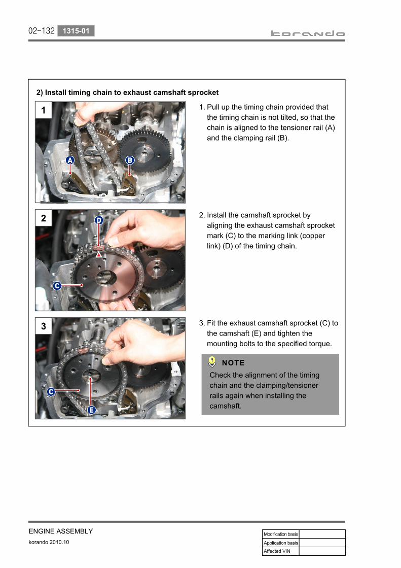
02-132
korando 2010.10
1315-01
ENGINE ASSEMBLY
2) Install timing chain to exhaust camshaft sprocket
Pull up the timing chain provided that the timing chain is not tilted, so that the chain is aligned to the tensioner rail (A) and the clamping rail (B).
1.
Install the camshaft sprocket by aligning the exhaust camshaft sprocket mark (C) to the marking link (copper link) (D) of the timing chain.
2.
Fit the exhaust camshaft sprocket (C) to the camshaft (E) and tighten the mounting bolts to the specified torque.
3.
Check the alignment of the timing chain and the clamping/tensioner rails again when installing the camshaft.
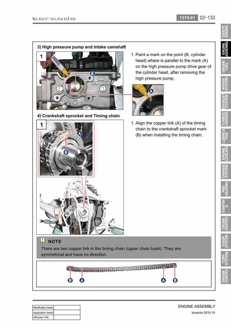
02-133
ENGINE ASSEMBLYkorando 2010.10
1315-01
3) High pressure pump and Intake camshaft
Paint a mark on the point (B, cylinder head) where is parallel to the mark (A) on the high pressure pump drive gear of the cylinder head, after removing the high pressure pump.
1.
Align the copper link (A) of the timing chain to the crankshaft sprocket mark (B) when installing the timing chain.
1.
4) Crankshaft sprocket and Timing chain
1
There are two copper link in the timing chain (upper chain bush). They are symmetrical and have no direction.

02-134
korando 2010.10
1315-01
ENGINE ASSEMBLY
5) Timing marks on intake and exhaust camshafts
Exhaust camshaft: Intake camshaft:
Align the two timing marks on the intake camshaft gear (A) to the one timing mark on the exhaust camshaft gear (B).
1.
Paint marks on the marking point of the high pressure (C) and the adjacent gear (D).
2.
Align the marks on the cylinder head (B) and the fuel high pressure pump (D) when installing the fuel high pressure pump.
3.
Replace the O-ring with a new one during installation.
The timing marks are on both sides of the intake and exhaust camshaft gears.
Apply oil around the O-ring when installing the high pressure pump.

02-135
ENGINE ASSEMBLYkorando 2010.10
1315-01
6) Crankshaft gear and Mass balance unit (MBU)
Paint a mark on the MBU.1.
Paint a mark on the point of the crankshaft gear timing (A) .
2.
Paint a mark on the MBU (B) while the pin hole (A) of the MBU balance shaft facing downwards.
-
Align the marks on the crankshaft gear and MBU as shown in the figure (A) when installing the MBU. The timing mark (A) on the MBU can be checked under the vehicle (B).
3.3
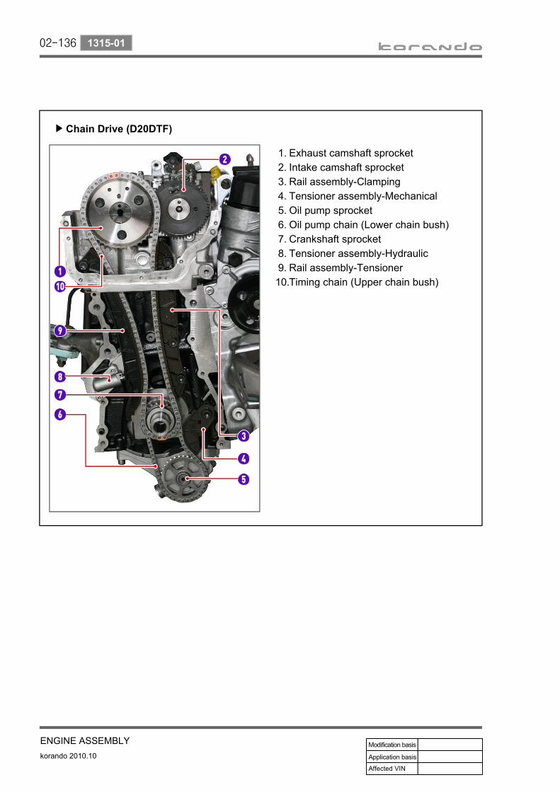
02-136
korando 2010.10
1315-01
ENGINE ASSEMBLY
Chain Drive (D20DTF)▶
Exhaust camshaft sprocketIntake camshaft sprocketRail assembly-ClampingTensioner assembly-MechanicalOil pump sprocketOil pump chain (Lower chain bush)Crankshaft sprocketTensioner assembly-HydraulicRail assembly-TensionerTiming chain (Upper chain bush)
1.2.3.4.5.6.7.8.9.
10.

02-137
ENGINE ASSEMBLYkorando 2010.10
1533-08
Pump assy - Oil pumpRing - SealPan assy - OilBoltPlug - DrainBoltSwitch assy - Oil level
1.6.8.
10.11.21.30.
Tube assy - Oil dipstickGauge assy - Oil dipstickO-ringBoltO-ringSealantCover - Dust
31.32.33.34.37.44.45.
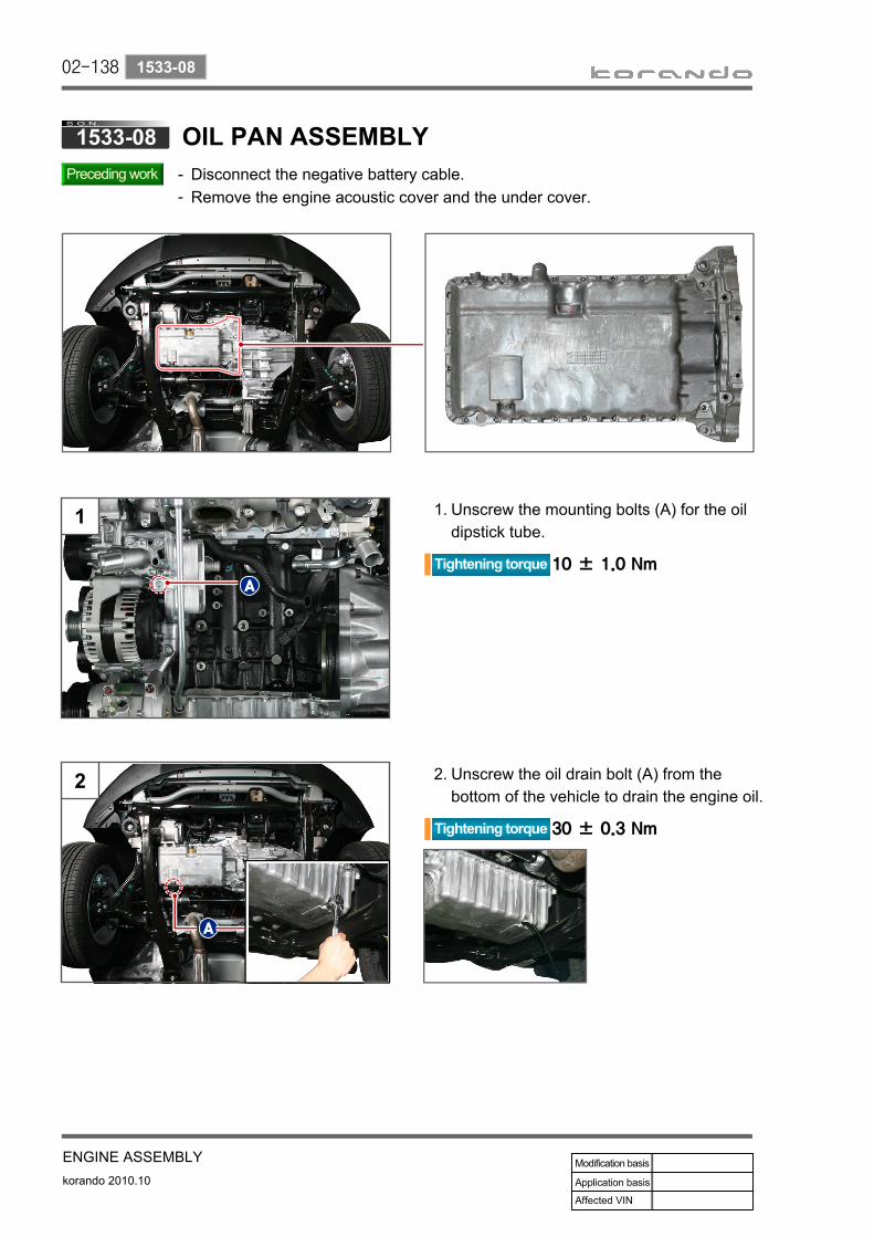
02-138
korando 2010.10
1533-08
ENGINE ASSEMBLY
Disconnect the negative battery cable.Remove the engine acoustic cover and the under cover.
--
Unscrew the mounting bolts (A) for the oil dipstick tube.
1.
Unscrew the oil drain bolt (A) from the bottom of the vehicle to drain the engine oil.
2.
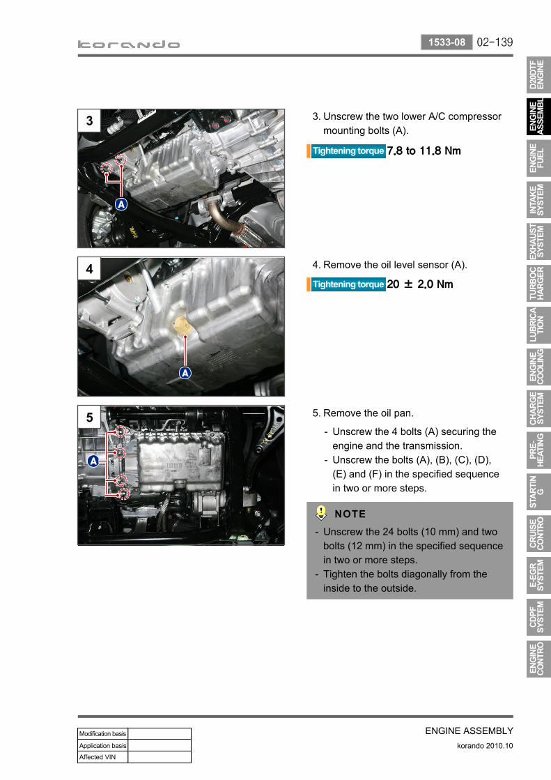
02-139
ENGINE ASSEMBLYkorando 2010.10
1533-08
Unscrew the two lower A/C compressor mounting bolts (A).
3.
Remove the oil level sensor (A).4.
Remove the oil pan.5.
Unscrew the 4 bolts (A) securing the engine and the transmission.Unscrew the bolts (A), (B), (C), (D), (E) and (F) in the specified sequence in two or more steps.
-
-
Unscrew the 24 bolts (10 mm) and two bolts (12 mm) in the specified sequence in two or more steps.Tighten the bolts diagonally from the inside to the outside.
-
-

02-140
korando 2010.10
1533-08
ENGINE ASSEMBLY
Be careful not to damage the oil pan.-
Push the oil dipstick tube to remove the oil pan.
6.
Make sure that the oil in the oil pan does not leak.When installing:
Remove the foreign materials by cleaning the oil pan.Apply the specified sealant on the mounting surface of the oil pan evenly. (DB 2210: 661 989 56 A0)Tighten the oil pan mounting bolts to the specified torque.
1.2.
3.
Install in the reverse order of removal.7.
Sealant application location▶
B M6X20 18 EA 10 ± 1 Nm
C M8X40 2 EA 25 ± 1 Nm
D M6X35 2 EA 10 ± 1 Nm
E M6X85 2 EA 10 ± 1 Nm
F M6X120 2 EA 10 ± 1 Nm
A M6X20 18 EA 10 ± 1 Nm
Apply sealant to the oil pan.Sealant P/N: 665 989 50 A0Do not pull out the oil dipstick tube completely from the oil pan.
-
-
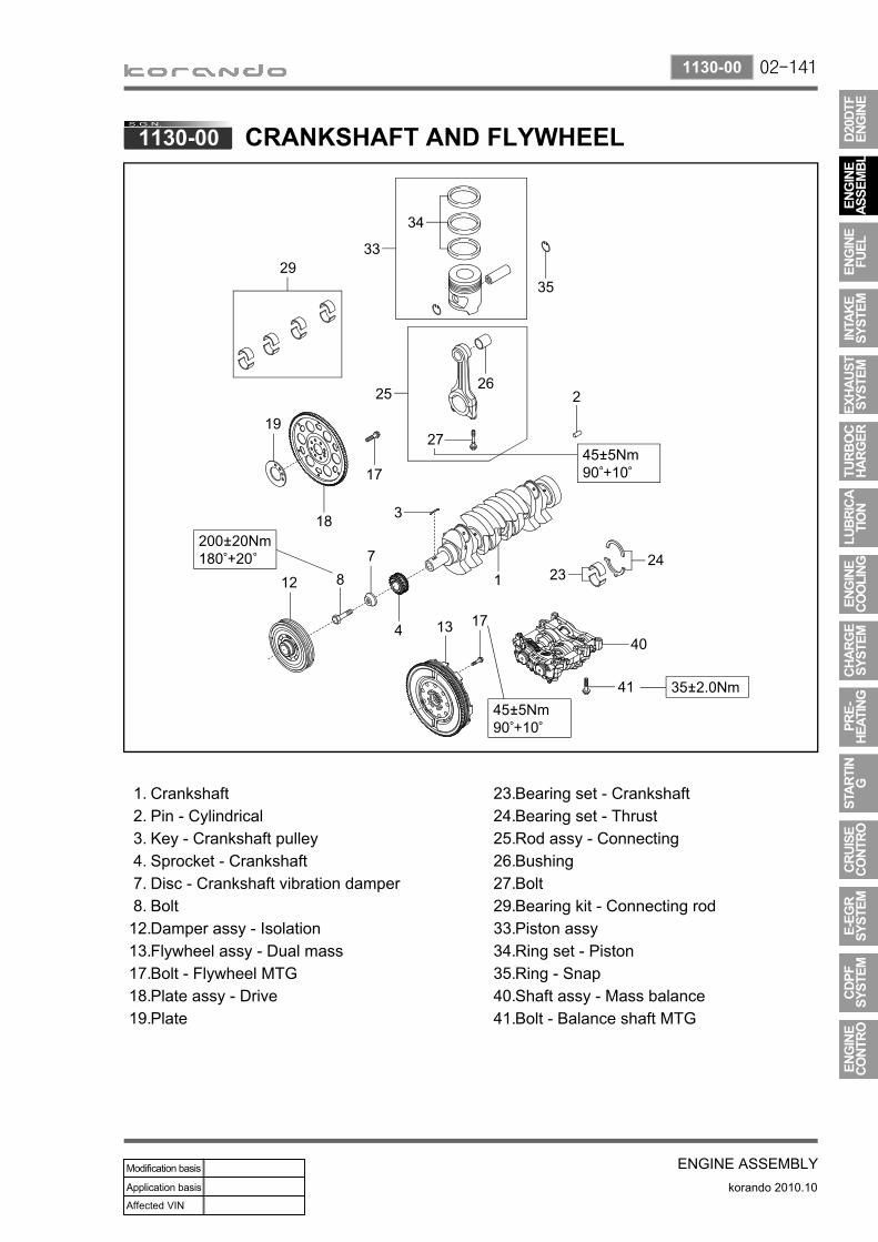
02-141
ENGINE ASSEMBLYkorando 2010.10
1130-00
CrankshaftPin - CylindricalKey - Crankshaft pulleySprocket - CrankshaftDisc - Crankshaft vibration damperBoltDamper assy - IsolationFlywheel assy - Dual massBolt - Flywheel MTGPlate assy - DrivePlate
1.2.3.4.7.8.
12.13.17.18.19.
Bearing set - CrankshaftBearing set - ThrustRod assy - ConnectingBushingBoltBearing kit - Connecting rodPiston assyRing set - PistonRing - SnapShaft assy - Mass balanceBolt - Balance shaft MTG
23.24.25.26.27.29.33.34.35.40.41.

02-142
korando 2010.10
1130-40
ENGINE ASSEMBLY
Disconnect the negative battery cable.Remove the engine acoustic cover and the under cover.Remove the oil pan assembly.
---
Remove the oil pan assembly.1.
Remove the MBU (A).2.
Unscrew the MBU bolts (B).-
Unscrew the MBU mounting bolts in the specified sequence in two or more steps as shown in the figure.
Install in the reverse order of removal.3.
For more information about the oil pan assembly, refer to the section "Oil Pan Assembly" of Chapter "Engine Assembly".
Tighten the bolts in the reverse order of removal in 2 or 3 steps with the specified torque.

02-143
ENGINE ASSEMBLYkorando 2010.10
1130-40
Cautions for installation▶
Paint a mark on the MBU.1.Paint a mark on the MBU (B) while the pin hole (A) of the MBU balance shaft facing downwards.
-
Paint a mark on the point of the crankshaft gear timing (A) .
2.
Align the marks on the crankshaft gear and MBU as shown in the figure (A) when installing the MBU. The timing mark (A) on the MBU can be checked under the vehicle (B).
3.3
Paint timing marks on the crank gear and MBU to easily identify.

02-144
korando 2010.10
1130-13
ENGINE ASSEMBLY
Disconnect the negative battery cable.Remove the engine acoustic cover and the under cover.
--
Remove the engine and transaxle assembly (sub frame) together.
1.
Remove the 6M/T assembly and then clutch disc and cover.
2.
Fit the DMF assembly (A) using a special tool (T99110010A).
3.
For further information, refer to the section "Engine and Transaxle Assembly" of Chapter "Engine Assembly".
Remove the 6M/T assembly and then clutch disc and cover.

02-145
ENGINE ASSEMBLYkorando 2010.10
1130-13
Unscrew the DMF.4.
Unscrew the 8 bolts.-
Install in the reverse order of removal.5.
Dual mass flywheel (DMF) assembly

02-146
korando 2010.10
1120-00
ENGINE ASSEMBLY
Preceding work▶
Remove the sub frame assembly.1.
Remove the engine and transaxle module.Make sure that it does not interfere with the surrounding parts in the engine compartment.
--
Remove the power transfer unit (PTU).2.
For further information, refer to the section "AWD" of Chapter "Chassis".

02-147
ENGINE ASSEMBLYkorando 2010.10
1120-00
a. Remove the front side transmission mounting (A). - Unscrew the through bolt (B). - Unscrew the mounting bolts (C).
Unscrew the transmission mounting bolts on the front sub frame, and remove the engine assembly from the front sub frame assembly.
3.
b. Remove the rear side transmission mounting (D). - Unscrew the through bolt (E). - Unscrew the mounting bolts (F).
When removing the sub frame and engine & transaxle as a unit, check that it is fitted to the engine and transmission jack securely, for safety reason.If the safety is secured, install the chain to the engine with a engine crane to remove the sub frame.
1.
2.

02-148
korando 2010.10
1120-00
ENGINE ASSEMBLY
After removing the engine assembly from the sub frame and remove the surrounding components of engine to install the engine to the engine stand.
4.
Throttle body assembly Starter assembly
CDPF assembly and bracket

02-149
ENGINE ASSEMBLYkorando 2010.10
1120-00
Install the engine bracket to the engine assembly and mount the engine assembly to the engine hanger using a jack for engine.
6.
Engine bracket on the left
Remove the automatic transmission assembly with the engine crane and transmission jack firmly fitted.
5.
For further information, refer to the section "Transmission" of Chapter "Chassis".
Engine bracket on the right

02-150
korando 2010.10
1120-00
ENGINE ASSEMBLY
2) Disassembling and Assembling
with EPSIdler pulley No. 3
Idler pulley No. 2
Crankshaft pulley
Auto tensioner
A/C compressor
Power steering pump
Water pump pulley
Alternator
Idler pulley No. 1
Fuel filterVacuum pump

02-151
ENGINE ASSEMBLYkorando 2010.10
1120-00
Remove the fan belt.Turn the tension release bolt (B) of the pivot damped tensioner (auto tensioner) clockwise (C) with a tension release tool (A) to release the tension before removing the fan belt.
1.
Unscrew the mounting A (17 mm) and B (14 mm) to remove the pivot damped tensioner.
2.
Remove the engine mounting, alternator connector and air compressor connector.
Auto tensioner assembly
1 Belt tensioner
2 Tensioner housing
3 Belt tensioner pulley
4 Belt tensioner pulley cover

02-152
korando 2010.10
1120-00
ENGINE ASSEMBLY
Remove the fan belt idle bearing 1 (A) and 2 (B).
3.
Remove the idler pulley no. 1 (A) bolt (T50).
-
Remove the idler pulley no. 2 (B) bolt (T50).
-
Remove the fan belt idler pulley 1 (A) and 2 (B) caps.
-
For the vehicle with electric power steering (EPS), the idler bearing no. 3 is mounted to the power steering pump position.
1 Idler pulley cover No. 1
2 Idler pulley No. 1
3 Idler pulley No. 1 mounting bolt
4 Idler pulley cover No. 2
5 Idler pulley No. 2
6 Idler pulley No. 2 mounting bolt
Idler pulley assembly No. 2
Idler pulley assembly No. 1

02-153
ENGINE ASSEMBLYkorando 2010.10
1120-00
Unscrew the 4 mounting bolts (13 mm) for A/C compressor to remove the compressor.
4.
Unscrew the mounting bolt A (17 mm) and B (15 mm) to remove the alternator.
5.
Push the bracket bushing in the arrow direction (A) when removing the alternator assembly.
5

02-154
korando 2010.10
1120-00
ENGINE ASSEMBLY
Remove the power steering pump.6.
Unscrew the two lower mounting bolts (12 mm).
-
Remove the power steering pump assembly using a flat-bladed screw driver.
-
Remove the bolt (13 mm) and nut (13 mm).
-
Confirm that no power steering oil is leaking.
For the vehicle with ESP, idler pulley no. 3 is mounted instead of power steering pump.

02-155
ENGINE ASSEMBLYkorando 2010.10
1120-00
Remove the turbocharger oil pipe.7.
Remove the oil supply pipe.a.
Remove the oil return pipe.b.
Disconnect the oil supply pipe screw fitting (A, 17 mm) on the cylinder block.Unscrew the hollow bolt (B, 14 mm) securing the oil supply pipe.
-
-
Replace the copper washer and gasket with new ones when installing.
Unscrew the two return pipe hexagon bolts (C, 5 mm) on the turbocharger.Unscrew the two return pipe hexagon bolts (D, 5 mm) on the cylinder block.
-
-

02-156
korando 2010.10
1120-00
ENGINE ASSEMBLY
Remove the turbocharger support bar.8.
Unscrew the bolt (A, 12 mm) and nut (3 mm).Unscrew the bolt (B, 13 mm).
Remove the turbocharger.9.
Unscrew the turbocharger bolt (A, 13 mm). Unscrew the two nuts (B, 13 mm).
Replace the 3-hole exhaust gasket with a new one when installing.

02-157
ENGINE ASSEMBLYkorando 2010.10
1120-00
Unscrew the two bolts (14 mm) and remove the engine hanger bracket (A).
10.
Unscrew the 10 bolts (14 mm) to remove the exhaust manifold.
12.
Remove the 3 hexagon bolts (14 mm) and remove the exhaust protect cover (B).
11.
Replace the exhaust gasket with a new one when installing.Part number: 6711420380
Unscrew the nuts slowly in two or more stages to prevent distortion of the exhaust manifold and cylinder head.
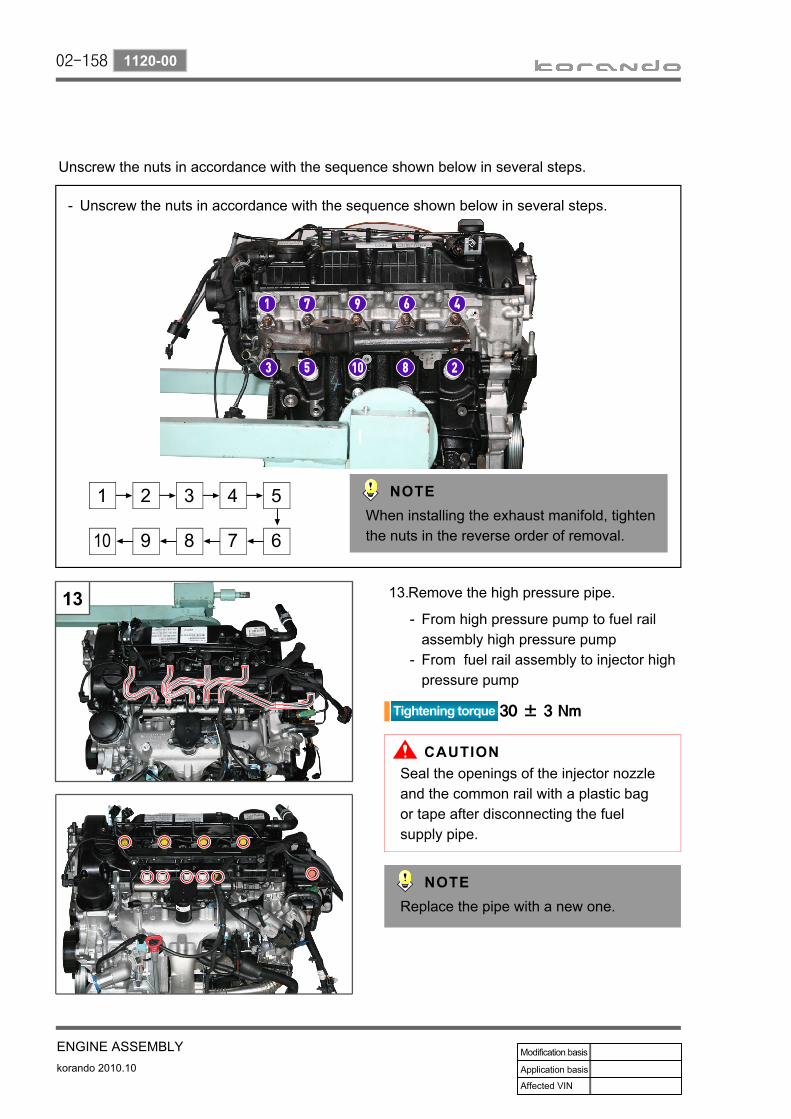
02-158
korando 2010.10
1120-00
ENGINE ASSEMBLY
Unscrew the nuts in accordance with the sequence shown below in several steps.
When installing the exhaust manifold, tighten the nuts in the reverse order of removal.
Unscrew the nuts in accordance with the sequence shown below in several steps.-
Remove the high pressure pipe. 13.
Replace the pipe with a new one.
From high pressure pump to fuel rail assembly high pressure pumpFrom fuel rail assembly to injector high pressure pump
-
-
Seal the openings of the injector nozzle and the common rail with a plastic bag or tape after disconnecting the fuel supply pipe.

02-159
ENGINE ASSEMBLYkorando 2010.10
1120-00
EGR valve
E-VGT Actuator
Crank position sensor
Knock sensor No. 2
EGR bypassKnock sensor No. 1
T-MAP sensor
Variable swirl valve
Fuel rail pressure sensor
Coolant temperature
sensor
IMV valveCam position sensor
Fuel temperature
sensor

02-160
korando 2010.10
1120-00
ENGINE ASSEMBLY
Remove the main wiring.14.
Remove the main wiring.-
Unscrew the 4 main wiring harness mounting bolts (10 mm).
-
Be careful not to damage the cable and connector.
Unscrew the bolt (10 mm) to remove the oil dipstick tube.
15.
Unscrew the two intake duct side bolts (A, 10 mm) andtwo E-EGR cooler side bolts (B, 13 mm) to remove the EGR cooler pipe.
16.
Replace the gasket with a new one.

02-161
ENGINE ASSEMBLYkorando 2010.10
1120-00
Remove the intake duct.17.
Unscrew the 3 bolts (B, 13 mm) to remove the intake duct.
-
Unscrew the 3 bolts (A, 13 mm) to remove the intake duct bracket.
-
Remove the E-EGR bypass solenoid valve and vacuum hose.
18.
Remove the E-EGR cooler.19.
Disconnect the vacuum hose.
Disengage the clamp (A) and disconnect the E-EGR cooler outlet hose. Unscrew the mounting bolts (B) of the EGR.Unscrew the E-EGR cooler bolts (C).
-
-
-
Make sure that the coolant in the oil cooler does not leak.
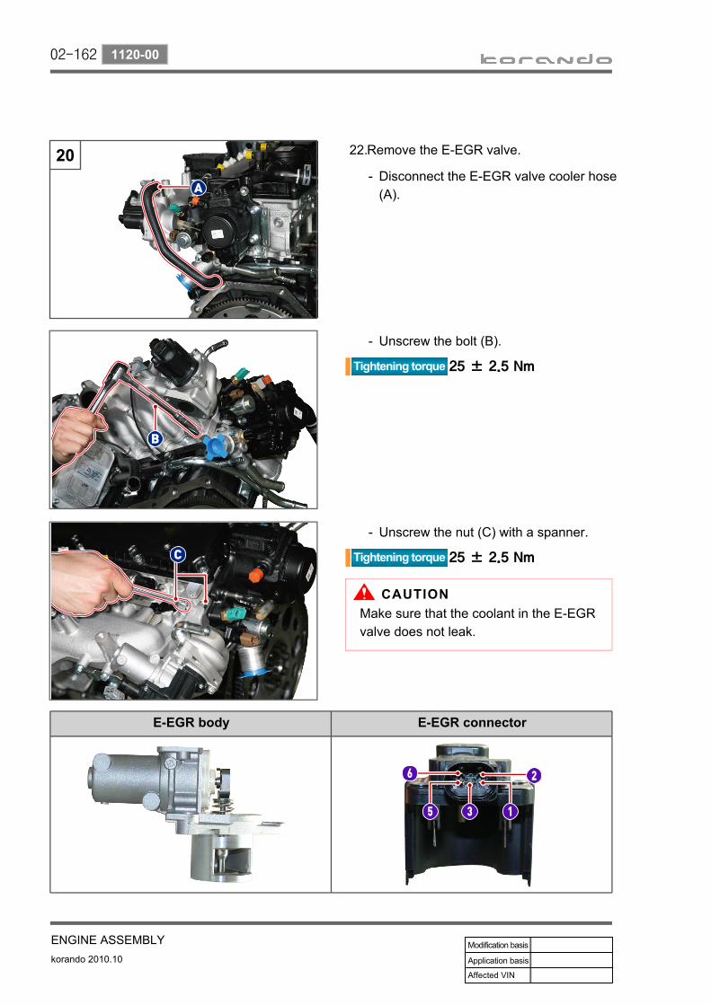
02-162
korando 2010.10
1120-00
ENGINE ASSEMBLY
Remove the E-EGR valve.22.
Unscrew the bolt (B).-
Disconnect the E-EGR valve cooler hose (A).
-
Unscrew the nut (C) with a spanner.-
Make sure that the coolant in the E-EGR valve does not leak.
E-EGR body E-EGR connector

02-163
ENGINE ASSEMBLYkorando 2010.10
1120-00
Unscrew the 8 bolts (13 mm) to remove the intake manifold.
21.
Unscrew the nuts in accordance with the sequence shown below in several steps.
When installing, tighten in the reverse order of removal.
Replace the gasket with a new one.
Unscrew the bolts slowly in two or more stages to prevent distortion of the intake manifold and cylinder head.
When installing, tighten in the reverse order of removal in 2 or 3 steps with the specified torque.

02-164
korando 2010.10
1120-00
ENGINE ASSEMBLY
Remove the oil cooler assembly. 22.
Unscrew the 7 bolts (13 mm) to remove the oil filter assembly.
-
Remove the knock sensor No. 1 and No. 2.
23
Disengage the clamp and disconnect the oil cooler inlet hose.
-
When installing the knock sensor, the No. 1 and No. 2 cylinder wirings should face 3 o'clock, and No.3 and No.4 cylinder wirings should face 9 o'clock.
NO. 1 NO. 2
No. Size Specified torque
A M8X40 25 ± 2.5 Nm
B M8X120 25 ± 2.5 Nm
C M8X140 25 ± 2.5 Nm
NO. 1 NO. 2
Unscrew the bolts (A). -

02-165
ENGINE ASSEMBLYkorando 2010.10
1120-00
특수 공구 사용 사진
Unscrew the 3 hexagon bolts (6 mm) to remove the fuel high pressure pump.
24.
Unscrew the two hexagon bolts (6 mm) to remove the common rail.
25.
Remove the injector.26.
Remove the injector using a special tool.b.
Check the belt timing marks before removing the fuel high pressure pump.
Unscrew the two Torx socket bolts (6 mm) to remove the injector clamp.
a.
Special tool: 000 000 00 00

02-166
korando 2010.10
1120-00
ENGINE ASSEMBLY
(A) Injectormark
(B) Cylinderhead cover mark
C3I code marked on the upper side of injector
Engine serial number and C3I code for injector are printed on 2 labels
C3I [Improved Individual Injector Calibration]
C3I code Consists of 20 digits(Numbers (1 to 9) and alphabetical characters except I, O, Q, V)
MDP learning During driving and idling
Injection nozzle 8 EA
a. C3I code for injector
The C3I code is marked on the sides of the injector and the cylinder head, and consists of 20 digits. The C3I code is listed as 20 digits consist of numbers (1 to 9) and alphabetical characters except I, O, Q, V.
ENG NO: 000000000000001. 123456789012345678902. 123456789012345678903. 12345678901234567890
ENG NO: 000000000000004. 12345678901234567890
Engine serial number and C3I code for injector are printed on labels on cylinder head coverCheck the C3I code when replacing injectors.
Always check the C3I code for each cylinder with the SIW diagnostic device.
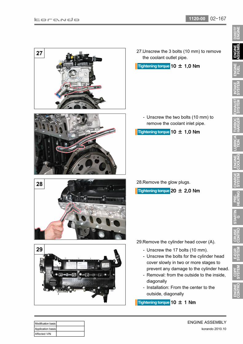
02-167
ENGINE ASSEMBLYkorando 2010.10
1120-00
Unscrew the 3 bolts (10 mm) to remove the coolant outlet pipe.
27.
Unscrew the two bolts (10 mm) to remove the coolant inlet pipe.
-
Remove the glow plugs.28.
Remove the cylinder head cover (A).29.
Unscrew the 17 bolts (10 mm).Unscrew the bolts for the cylinder head cover slowly in two or more stages to prevent any damage to the cylinder head.Removal: from the outside to the inside, diagonallyInstallation: From the center to the outside, diagonally
--
-
-

02-168
korando 2010.10
1120-00
ENGINE ASSEMBLY
Crankshaft timing
Camshaft timing
Remove the vacuum pump (A).30.
Setting the correct timing (A) of the crankshaft and camshaft makes the slot of the vacuum pump parallel to B-B'.Make sure that it is lined up as shown in the figure (B-B').
BB’
Unscrew the 13 bolts (B, 10 mm).-

02-169
ENGINE ASSEMBLYkorando 2010.10
1120-00
Remove the front cover (A).31.
Remove the engine mounting lower bracket (A).
32.
Position to pry out front cover
Do not apply excessive force when prying out the front cover, as it can cause entry of foreign material and engine body damage.
Unscrew the 5 bolts (B, 10 mm).-
Unscrew the 3 bolts (B, 17 mm).-
Fit the chain tensioner.33.Remove the chain tensioner plug cap (A).
-

02-170
korando 2010.10
1120-00
ENGINE ASSEMBLY
Compress the hydraulic chain tensioner by pushing a flat-bladed screwdriver (B) in the direction (C).
-
Fit and secure the mounting pin (D) by inserting it to the hydraulic chain tensioner compressed by the flat-bladed screwdriver.
-
Use a piece of cloth not to damage the plug threads.
Secure the octagon spanner seat (A) of the intake camshaft with a 30 mm spanner, and unscrew the exhaust camshaft sprocket bolts (B) to remove the sprocket.
34.
Exhaust camshaft sprocket

02-171
ENGINE ASSEMBLYkorando 2010.10
1120-00
Secure the timing chain as shown in the figure (A) to prevent the chain from falling into the cylinder block.
35.
Unscrew the hexagon bolt (T50) to remove the clamping rail on the tensioner side.
36.
When removing the clamping rail, put aside the chain so as not to interfere with it as shown in the figure.

02-172
korando 2010.10
1120-00
ENGINE ASSEMBLY
Remove the camshaft bearing cap (A).37.
Unscrew the camshaft mounting bolts slowly in two or more stages according to the specific sequence stated below.(1) Intake camshaft: IN, 6, 8(2) Exhaust camshaft: EX, 2, 4(3) Intake camshaft: 5, 7, 9(4) Exhaust camshaft: 1, 3
-
Tightening torque
EX, IN bearing cap 25 ± 2.5 Nm
No. 1 to 9 bearing caps 10 ± 1.0 NmAlways tighten to the specified torque so as not to damage the camshaft.
Remove the intake/exhaust camshafts.38.

02-173
ENGINE ASSEMBLYkorando 2010.10
1120-00
Remove the camshaft and no. 1 lower cap (A).
39.
Remove the finger follower and HLA device (A).
40.
Exhaust camshaft: Intake camshaft:
Take extreme care because the HLA device is very hot right after the engine is turned off.If the removed finger follower and HLA device is easily pressed, it means that the oil has been drained. In this case, replace it with a new one.
-
-
The timing marks are on both sides of the intake and exhaust camshaft gears.
Align the timing marks on the intake/exhaust camshaft sprockets.
Apply engine oil before installing.
Timing marks on intake and exhaust camshafts
Align the two timing marks on the intake camshaft gear (A) to the one timing mark on the exhaust camshaft gear (B).

02-174
korando 2010.10
1120-00
ENGINE ASSEMBLY
Unscrew the bolts in 2 or more steps.Apply oil to the head bolt thread.
--
Unscrew the cylinder head shoulder bolts (A, T6 mm).
41.
Remove the cylinder head bolts (A). 42.
Unscrew the cylinder head bolts in two or more stages according to the specific sequence.
-
Cylinder head bolt wrench
Unscrew the mounting bolts for the cylinder head in the sequence shown in the figure below.

02-175
ENGINE ASSEMBLYkorando 2010.10
1120-00
Tightening process for cylinder head bolts
Torque wrench45 ± 5 Nm
Put matchmark(Cylinder head/
head bolt)
Tighten - 1st90°±10°
Tighten - 2nd90°±10°
Tighten - 3rd90°±10°
Remove the cylinder head gasket (A).43.
Protrusion amount of piston
Gasket thickness
0.475 to 0.540 mm 1.2t
0.541 to 0.649 mm 1.3t
0.650 to 0.745 mm 1.4t
Cylinder head Gasket thickness mark
Gasket thickness 1.3t

02-176
korando 2010.10
1120-00
ENGINE ASSEMBLY
Remove the crankshaft pulley.44.
Lock the flywheel and tighten the crankshaft pulley mounting center bolt (27 mm) with a special tool.
a.
Remove the bracket for A/C compressor.45.
Run the engine and remove the oil level switch (29 mm).Tool: Long socket 29 mm
46.

02-177
ENGINE ASSEMBLYkorando 2010.10
1120-00
Remove the engine oil pan.47.
Unscrew the oil pan mounting bolt by checking the specifications of the bolt. Carefully remove the oil pan.
a.
b.
Tightening torque Nm
M6x20 18 EA 10±1
M8x40 2 EA 25±1
M6x35 2 EA 10±1
M6x85 2 EA 10±1
M6x120 2 EA 10±1
Make sure that the oil in the oil pan does not leak.When installing:
Remove the foreign materials by cleaning the oil pan.Apply the specified sealant on the mounting surface of the oil pan evenly. (DB 2210: 661 989 56 A0)Tighten the oil pan mounting bolts to the specified torque.
1.2.
3.
Sealant application location▶

02-178
korando 2010.10
1120-00
ENGINE ASSEMBLY
Remove the drive plate.48.
Remove the Drive plate A and B.b.
Remove the crankshaft position sensor.49.
Do NOT keep the trigger ring near the magnetic attach driver and any magnet.
Fit the drive plate with a special tool and unscrew the bolts.
a.
Remove the dust cover (A) and crank angle sensor wiring.
a.
Unscrew the mounting bolts and remove the position sensor (A) and trigger ring (B).Tool: Hexagon L wrench, 5 mm
b.

02-179
ENGINE ASSEMBLYkorando 2010.10
1120-00
Remove the mass balance unit.50.
Remove the crankshaft rear seal cover 51.
Remove the (A).a.
Unscrew the 5 bolts (10 mm).-
Unscrew the MBU mounting bolts in the specified sequence in two or more steps as shown in the figure.
Tighten the bolts in the reverse order of removal in 2 or 3 steps with the specified torque.
Check the timing marks on the crankshaft and MBU.

02-180
korando 2010.10
1120-00
ENGINE ASSEMBLY
Remove the timing gear case cover (TGCC).
52.
Remove the timing gear case cover (TGCC).
-
Unscrew the bolts (A), (B) and (C).-
Part name Size Tightening
torque
A Bolt M6X40 10 ± 1.0 Nm
B Bolt M6X45 10 ± 1.0 Nm
C Bolt M6X50 10 ± 1.0 Nm
Cautions for installation
Apply sealant to the timing gear case cover.Sealant P/N: 665 989 50 A0
-
-
Height difference specification 0.2 mm or less
Install the lower front cover and check the height difference with the cylinder block.Make sure that the engine oil does not leak while the engine oil pan is fitted.
-
-

02-181
ENGINE ASSEMBLYkorando 2010.10
1120-00
Remove the timing chain.53.
Remove the clamping rail assembly. Tool: T45
54.
Remove the hydraulic chain tensioner (A). 55.Unscrew the bolt (B).-
Check the timing marks on the timing chain and the crankshaft before removing.

02-182
korando 2010.10
1120-00
ENGINE ASSEMBLY
Remove the mechanical tensioner assembly.
56.
Unscrew the bolt (T35) to remove the chain tensioner.
-
Pull the tensioner to (A) position and insert the fixing pin (B) to secure it.
-
Remove the oil pump assembly (A) and lower chain bush (B).
57.
Tilt the oil pump in the direction (A) and remove the oil pump assembly and lower chain bush together.
-
Unscrew the 3 oil pump mounting bolts.Tool: Hexagon bit socket, 6 mm
-

02-183
ENGINE ASSEMBLYkorando 2010.10
1120-00
Remove the piston assembly. 58.
Remove the carbon on the cylinder block.b.
Unscrew the No. 1 and No. 4 bearing cap bolts and remove the piston assembly.
c.
Put marks on the piston rod cap and connecting rod cap so as not to mix up. Use the cylinder #1 as a reference.
a.
If an excessive force is applied to remove the piston assembly without removing the carbon on the cylinder block, the inside surface of the cylinder and piston assembly can be scratched to the piston ring can be damaged.
58

02-184
korando 2010.10
1120-00
ENGINE ASSEMBLY
Turn the crankshaft 180° and remove
the No. 2 and No. 3 piston assembly as described in c and d.
d.
Piston assembly
Remove the snap ring from the piston and remove the piston pin. Remove the piston and connecting rod.Remove the piston ring from the piston and put it together.
-
--
Replace the piston, bearing and snap ring with new ones.
Part name
1 Piston
2 Connecting rod
3 Connecting rod cap
4 Connecting rod upper bearing
5 Connecting rod lower bearing
6 Piston pin
7 Snap ring
8 Top ring
9 Second ring
10 Oil ring

02-185
ENGINE ASSEMBLYkorando 2010.10
1120-00
Remove the crankshaft. 59.
Remove the bolts slowly in 2 or more steps in the same sequence as removing the crankshaft main bearing caps to remove the main journal bearing caps.
-
Put marks on the crankshaft main journal bearing caps before removing it.
Remove the crankshaft main journal caps in the specified sequence.
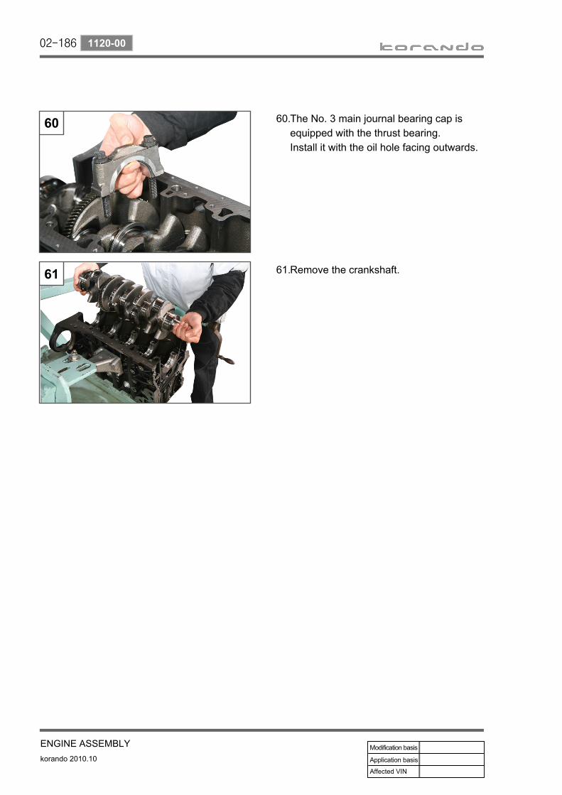
02-186
korando 2010.10
1120-00
ENGINE ASSEMBLY
The No. 3 main journal bearing cap is equipped with the thrust bearing.Install it with the oil hole facing outwards.
60.
Remove the crankshaft.61.

02-187
ENGINE ASSEMBLYkorando 2010.10
1120-00
3) Carried out checks(1) V-Belt
Put a chalk mark on the belt.Check the belt for any damage by rotating the engine.
Replace the belt if any damage is found as described below:
Rubber piece in the belt rib baseDust or sand
1.2.
Rib shaped in wedgeExposed belt cord on the rib base
3.4.
Torn tension cordWorn outer tension cord
5.6.

02-188
korando 2010.10
1120-00
ENGINE ASSEMBLY
Stripped rib on belt base7.
Cracked rib in lateral directionTorn rib
8.9.
Cracked rib in several lateral directions10.
Crack on back side of belt in lateral direction
11.

02-189
ENGINE ASSEMBLYkorando 2010.10
1120-00
(2) Cylinder Block
Measuring cylinder block bore▶
Wipe out the cylinder bore.Measure the bore size in axial direction and vertical direction on 3 points (1, 2, 3) with a bore gauge.
1.2.
Measuring points 1, 2, 3A. Axial directionB. Vertical directiona. Piston position at TDCb. Piston position at BTDCc. Oil ring position between TDC and BTDC

02-190
korando 2010.10
1120-00
ENGINE ASSEMBLY
(3) CrankshaftMeasuring crankshaft bearing bore▶
Crankshaft Journal▶
Measure the bore of the crankshaft bearing with a bore gauge.
Measure the bore of the crankshaft bearing journal with a micro meter.
Measure the values at 2 points (1, 2).Measure the values at the A, B and C as shown in the figure.If the average value of B and C is less than the value of A, then it can be used as actual average value. If the average value of B and C is greater than the value of A, then the value of A can be used as actual average value.
-
-
Measure the values at 3 points (A, B, C) and calculate the average value.If the average values of the bearing bore and journal diameter are not within the specified range, replace the bearing shell.
-
-

02-191
ENGINE ASSEMBLYkorando 2010.10
1120-00
(4) Piston and Connecting Rod
Measuring oil ring and compression ring clearances▶
Install the compression ring and oil ring to the piston using a special tool.
The opening section of the piston oil ring should be positioned at an interval of 120˚.
Piston ringCheck the piston ring for damage, wear and crack. Replace a damaged ring with a new one. When removing the piston, the piston ring should be replaced together. Measure the clearance between the piston ring and ring groove.
1.
2.
3.
No. 1 compression ring 0.20 to 0.35 mm
No. 2 compression ring 0.35 to 0.50 mm
No. 3 oil ring 0.20 to 0.40 mm
Piston ring free gapNo. 1 compression ring: 11.0 mmNo. 2 compression ring: 10.5 mmNo. 3 compression ring: 7.0 mm
*
Install the no.1 and no. 2 compression rings with the marks facing upwards.Thickness of no. 1 piston ring > Thickness of no. 2 piston ring Put the oil ring with the opening section positioned on the other side of the base opening.The oil ring has no direction.Make sure that the openings of the piston are not overlapped.
-
-
-
--

02-192
korando 2010.10
1120-00
ENGINE ASSEMBLY
4) Engine OverholeClean the cylinder bore, connecting rod, connecting rod bearing shell and piston thoroughly with compressed air.
1.
The oil spray nozzle injects the oil to the inside of the piston. Make sure that the oil spray nozzle pipe does not contact the connecting rod.
Top of cylinder block Bottom of cylinder block
Head bolt seatOil return grooveCoolant passage groove
1.2.3.
Oil jackCrankshaft main bearing No.Oil return groove
4.5.6.

02-193
ENGINE ASSEMBLYkorando 2010.10
1120-00
Bearings selection according to pin punch mark
Item Color Main bearing diameter (mm)
* Blue 68.500~68.506
** Yellow 68.506~68.513
*** Red 68.513~68.519
Select the crankshaft main bearing.2.
There are five punch marks on the bottom of the cylinder block (oil pan contact surface). These punch marks match to the mounting locations of each main bearing. Therefore, select the crankshaft upper main bearing according to these punch marks.Select the lower main bearing that is engaged to the crankshaft bearing cap by the mark on the crankshaft sprocket mounting surface.
a.
b.
Item Color Main bearing diameter (mm)
V Purple 63.9400~63.945
W White 63.945~63.950
R Red 63.950~63.955
G Yellow 63.955~63.960
B Blue 63.960~63.965
Bottom of cylinder block Mounting surface of crankshaft sprocket
Selecting crankshaft upper bearing Selecting crankshaft lower bearing

02-194
korando 2010.10
1120-00
ENGINE ASSEMBLY
Install the main bearing to the crankshaft upper side.
3.
Apply the engine oil to the upper bearing shell.
-
Fit the crankshaft to the cylinder block.4.
Install the upper thrust bearing to the No. 3 main journal.
5.
Install the thrust bearing so that its oil groove (A) faces outward.Remove the foreign materials on the thrust bearing.Insert the bearing after applying the engine oil.
-
-
-
Check the color of new main bearing and match it to the key groove (A) of the cylinder block. Install the bearing with the oil groove (B) aligned.
-
Make sure the oil holes of the cylinder block body are aligned with the oil holes of the bearing.

02-195
ENGINE ASSEMBLYkorando 2010.10
1120-00
Remove the main journal bearing caps.6.
The No. 3 main journal bearing cap is equipped with the thrust bearing. Therefore make sure that the oil groove (B) faces outwards when installing.
-
Install the No. 3 main journal bearing cap and thrust bearing (A).
-
Install it so that the part (A) of the main journal bearing cap faces the intake manifold.

02-196
korando 2010.10
1120-00
ENGINE ASSEMBLY
295
Tighten the main journal bearing cap mounting bolt to the specified torque.
-
Paint marks on the cap bolts after 1st tightening.
-
Angle-tighten the bolts to 130˚ ± 10˚
further in order at 2nd tightening.-
The appearance of the No. 2 and No. 5 main bearing cap bolts are different from each other.
Measure the end play of the crankshaft and adjust the thrust bearing so that the end play is within the specification.
-
Check the status and angle of the tightened bolt after 2nd tightening.

02-197
ENGINE ASSEMBLYkorando 2010.10
1120-00
Install the piston assembly.7.
Replace the piston, bearing and snap ring with new ones.
EnginePiston Cylinder bore
Part No. Marking No. -
D20DTF
671 030 06 17 - -
671 037 07 01 A A
671 037 08 01 X X
671 037 09 01 B B
671 037 10 01 +5 -
671 037 11 01 +10 -
Selecting piston oversize
Top of piston Top of cylinder block

02-198
korando 2010.10
1120-00
ENGINE ASSEMBLY
Insert the piston assembly No. 1 and No. 4 to the cylinder using a tool.
b.
Check the (←) mark on top of the
piston and make sure that this arrow faces the no. 1 cylinder while it is parallel to the crankshaft.Pay attention to the piston direction.
Apply engine oil to the piston surface and piston ring before installing.
a.
Stagger the piston rings so that the ring end gaps are approx. 120 deg apart.Make sure to install the piston and shell at the correct locations.
-
-

02-199
ENGINE ASSEMBLYkorando 2010.10
1120-00
Install the no. 1 and no. 4 caps while paying attention to the direction.
8.
Turn the crankshaft 180° and install
the No. 2 and No. 3 pistons in the same way as the no. 1 and no. 4 pistons.
a.
Angle-tighten them to 90˚ ± 10˚
further and check the tightened status.c.
Tighten the connecting rod cap bolts to the specified torque for the 1st tightening and put matchmarks on each connecting rod cap in the same way as before.
b.
If the piston reaches to BTDC with installed in the opposite direction, the oil jet can be damaged.
Oil jet groove
Make sure that the correct bearing cap and shell are mounted.

02-200
korando 2010.10
1120-00
ENGINE ASSEMBLY
Fit the crankshaft sprocket into the key groove.
9.
Install the engine oil pump assembly and lower chain bushing.
10.
Tighten the 3 wrench bolts (5 mm) to the specified torque.
b.
Tilt the oil pump assembly in the direction (A) and remove the oil pump assembly.
a.
Install the mechanical tensioner assembly (A).
11.
Mount the chain clamping rail (B) and tighten the two mounting bolts (T45) to the specified torque.
-
Tighten the bolt (T45) to the specified torque.
-

02-201
ENGINE ASSEMBLYkorando 2010.10
1120-00
Timing of camshaft sprocket and crankshaft sprocket
Install the hydraulic tensioner assembly (A).
12.
Align the timing marks (copper mark) on the timing chain and crankshaft sprocket to install.
13.
Tighten the 2 wrench bolts (5 mm) to the specified torque.
-
Align the copper links of the timing chain.

02-202
korando 2010.10
1120-00
ENGINE ASSEMBLY
Mount the timing chain gear case cover (TGCC) and tighten the 10 mounting bolts (10 mm) to the specified torque.
14.
Unscrew the bolts (A), (B) and (C).-
Part name Size Tightening
torque
A Bolt M6X40 10 ± 1.0 Nm
B Bolt M6X45 10 ± 1.0 Nm
C Bolt M6X50 10 ± 1.0 Nm
Apply sealant to the timing case cover.Sealant part No.:
Height difference specification 0.2 mm or less
Tie the chain to the chain guide hole so that the chain is not displaced from the crankshaft sprocket.
Install the lower front cover and check the height difference with the cylinder block.Make sure that the oil in the oil pan does not leak.
-
-

02-203
ENGINE ASSEMBLYkorando 2010.10
1120-00
Checking MBU timing mark
Install the mass balance unit.15.Tighten the 6 mounting bolts in the specified sequence in two or more steps.
a.
Unscrew the MBU mounting bolts in the specified sequence in two or more steps as shown in the figure.
Tighten the bolts in the reverse order of removal in 2 or 3 steps with the specified torque.
Align the marks on the crankshaft gear and MBU as shown in the figure (A) when installing the MBU.

02-204
korando 2010.10
1120-00
ENGINE ASSEMBLY
Install the crank position sensor assembly.16.
Install the crankshaft with a tool.a.
Install the crank position sensor assembly carefully, so that the inner oil seal is not damaged, and tighten the 6 mounting bolts (10 mm) to the specified torque.
b.
Measure the crank position sensor air gap with a thickness gauge.
d.
Install the crank position sensor.c.
Air gap specification 0 mm or less
Height difference specification 0.2 mm or less
Check the height difference.
Do NOT keep the trigger ring near the magnetic attach driver and any magnet.

02-205
ENGINE ASSEMBLYkorando 2010.10
1120-00
Install the drive plate A and B.17.
Fit the crankshaft with a special tool (T9911 0010A).
a.
Screw the mounting bolts in two or more stages according to the specific sequence diagonally.
b.
Check the status and angle of the tightened bolt after 2nd tightening.
d.
Put matchmarks after 1st tightening.c.
Check the mating surface of the ring gear where the pinion gear contacts for wear.
Special tool: T9911 0010A

02-206
korando 2010.10
1120-00
ENGINE ASSEMBLY
Install the oil pan. 18.
Tighten the 24 bolts (10 mm) and two bolt (12 mm) in the specified sequence in two or more steps.Tighten the bolts diagonally from the inside to the outside.
a.
b.
Nm
M6x20 18 EA 10±1
M8x40 2 EA 25±1
M6x35 2 EA 10±1
M6x85 2 EA 10±1
M6x120 2 EA 10±1
Make sure that the oil in the oil pan does not leak.When installing:
Remove the foreign materials by cleaning the oil pan.Apply the specified sealant on the mounting surface of the oil pan evenly. (DB 2210: 661 989 56 A0)Tighten the oil pan mounting bolts to the specified torque.
1.2.
3.
Sealant application location▶

02-207
ENGINE ASSEMBLYkorando 2010.10
1120-00
Install the front oil seal (A) for the timing gear case cover (TGCC).
19.
Mount the crankshaft front seal-ring (A) to the TGCC and install it with a special tool (B).
-
Check the height difference of the engine oil pan and tighten the bolts to the specified torque.
c.
Height difference specification 0.2 mm or less

02-208
korando 2010.10
1120-00
ENGINE ASSEMBLY
Install the crankshaft pulley.20.
Fit the flywheel using a special tool (T9911 0010A).
a.
Tighten the crankshaft pulley center bolt (27 mm) to the specified torque with a special tool.
b.
Put matchmarks after 1st tightening.c.Check the status and angle of the tightened bolt after 2nd tightening.
d.
Special tool: T9911 0010A

02-209
ENGINE ASSEMBLYkorando 2010.10
1120-00
Install the cylinder head gasket after measuring the thickness of the protruded piston with a special tool.
21.
Fit a tool.a.
Measure the piston protrusion values in the axial direction of the crankshaft and calculate the average value.
c.
Measuring points (8 points)d.
Fit a dial gauge to the top of the cylinder block and adjust the zero point.
b.
Remove the foreign materials and the gasket residual on the surface of the cylinder block before measuring.
Measure each point 3 or more times and calculate the average value (total 8 measurement points).
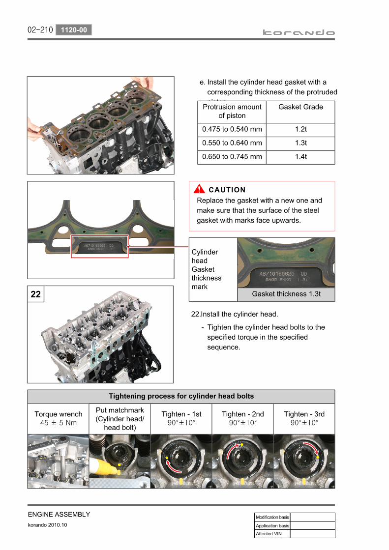
02-210
korando 2010.10
1120-00
ENGINE ASSEMBLY
Install the cylinder head gasket with a corresponding thickness of the protruded piston.
e.
Protrusion amount of piston
Gasket Grade
0.475 to 0.540 mm 1.2t
0.550 to 0.640 mm 1.3t
0.650 to 0.745 mm 1.4t
Install the cylinder head. 22.
Tighten the cylinder head bolts to the specified torque in the specified sequence.
-
Cylinder head Gasket thickness mark
Gasket thickness 1.3t
Tightening process for cylinder head bolts
Torque wrench45 ± 5 Nm
Put matchmark(Cylinder head/
head bolt)
Tighten - 1st90°±10°
Tighten - 2nd90°±10°
Tighten - 3rd90°±10°
Replace the gasket with a new one and make sure that the surface of the steel gasket with marks face upwards.

02-211
ENGINE ASSEMBLYkorando 2010.10
1120-00
Tightening sequence
Tighten the 3 wrench bolts (6 mm) for the cylinder head to the specified torque.
-
Screw the cylinder head bolts in two or more stages according to the specific sequence.
-
Apply oil on the threads of the cylinder head bolt before installing.Make sure to insert the new washer first.
-
-
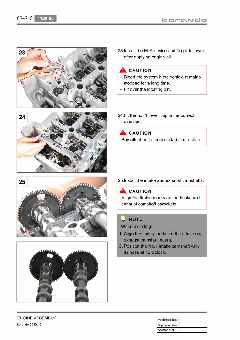
02-212
korando 2010.10
1120-00
ENGINE ASSEMBLY
Install the HLA device and finger follower after applying engine oil.
23.
Fit the no. 1 lower cap in the correct direction.
24.
Install the intake and exhaust camshafts.25.
Bleed the system if the vehicle remains stopped for a long time.Fit over the locating pin.
-
-
Pay attention to the installation direction.
Align the timing marks on the intake and exhaust camshaft sprockets.
Align the timing marks on the intake and exhaust camshaft gears.Position the No.1 intake camshaft with its nose at 12 o'clock.
1.
2.
When installing:

02-213
ENGINE ASSEMBLYkorando 2010.10
1120-00
Install the camshaft bearing cap. 26.
Tighten the bearing cap mounting bolts slowly in two or more stages from the inside to the outside.
-
Tightening torque
EX, IN bearing cap 25 ± 2.5 Nm
No. 1 to 9 bearing caps 10 ± 1.0 Nm
Always tighten to the specified torque so as not to damage the camshaft.
Insert the tensioner clamping rail (A).27.

02-214
korando 2010.10
1120-00
ENGINE ASSEMBLY
Cautions for installation▶
Pull up the timing chain provided that the timing chain is not tilted, so that the chain is aligned to the tensioner rail (A) and the clamping rail (B).
a.
Install the camshaft sprocket by aligning the exhaust camshaft sprocket mark (C) to the marking link (copper link) (D) of the timing chain.
b.
Fit the exhaust camshaft sprocket (C) to the camshaft (E) and tighten the mounting bolts to the specified torque.
c.
Install the timing chain.28.
Check the alignment of the timing chain and the clamping/tensioner rails again when installing the camshaft.
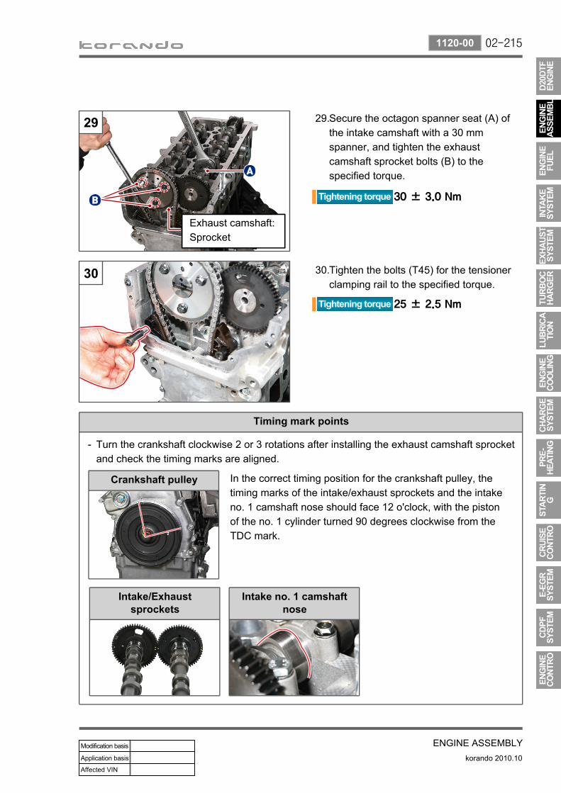
02-215
ENGINE ASSEMBLYkorando 2010.10
1120-00
Tighten the bolts (T45) for the tensioner clamping rail to the specified torque.
30.
Secure the octagon spanner seat (A) of the intake camshaft with a 30 mm spanner, and tighten the exhaust camshaft sprocket bolts (B) to the specified torque.
29.
Exhaust camshaft: Sprocket
Timing mark points
Turn the crankshaft clockwise 2 or 3 rotations after installing the exhaust camshaft sprocket and check the timing marks are aligned.
-
Crankshaft pulley
Intake/Exhaust sprockets
Intake no. 1 camshaft nose
In the correct timing position for the crankshaft pulley, the timing marks of the intake/exhaust sprockets and the intake no. 1 camshaft nose should face 12 o'clock, with the piston of the no. 1 cylinder turned 90 degrees clockwise from the TDC mark.

02-216
korando 2010.10
1120-00
ENGINE ASSEMBLY
Install the high pressure pump. 31.
Tighten the 3 hexagon wrench bolts (5 mm) to the specified torque.
a.
Replace the O-ring with a new one during installation.
Align the timing mark on the high pressure pump gear with the one on the intake camshaft gear.
O-ring
Apply sealant around the O-ring when installing the high pressure pump.Sealant part No.:
The timing mark on the high pressure pump should be turned clockwise 2.5 pitches. Check the timing marks when installing.
-
-
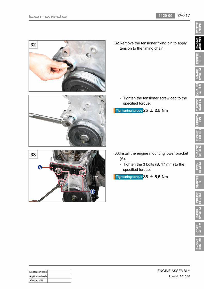
02-217
ENGINE ASSEMBLYkorando 2010.10
1120-00
Remove the tensioner fixing pin to apply tension to the timing chain.
32.
Tighten the tensioner screw cap to the specified torque.
-
Install the engine mounting lower bracket (A).
33.
Tighten the 3 bolts (B, 17 mm) to the specified torque.
-

02-218
korando 2010.10
1120-00
ENGINE ASSEMBLY
Install the front cover (A).34.
Install the vacuum pump.Tighten the 3 vacuum pump mounting bolts (10 mm) to the specified torque.
35.
Apply sealant and tighten the 5 front cover bolts (10 mm) to the specified torque.Install the crank position sensor (B).
-
-
The O-ring for the vacuum pump should be replaced with a new one.
BB’
When installing the vacuum pump, make sure that it is lined up as shown in the figure (B-B').
-
Setting the correct timing (A) of the crankshaft and camshaft makes the slot of the vacuum pump parallel to B-B'.

02-219
ENGINE ASSEMBLYkorando 2010.10
1120-00
Fit the cylinder head cover to the cylinder head and tighten the 17 cylinder head cover bolts (10 mm) in two or more steps to the specified torque.
36.
Install the injector. Tighten the two injector clamp mounting bolts (6 mm) to the specified torque while securing two injectors with one mounting clamp.
37.
C3I [Improved Individual Injector Calibration]
C3I code Consists of 20 digits(Numbers (1 to 9) and alphabetical characters except I, O, Q, V)
MDP learning During driving and idling
Injection nozzle 8 EA
Unscrew the bolts for the cylinder head cover slowly in two or more stages to prevent any damage to the cylinder head cover.
Always check the C3I code for each cylinder with the SIW diagnostic device.

02-220
korando 2010.10
1120-00
ENGINE ASSEMBLY
(A) Injectormark
(B) Cylinderhead cover mark
C3I code marked on the upper side of injector
Engine serial number and C3I code for injector are printed on 2 labels
a. C3I code for injector
The C3I code is marked on the sides of the injector and the cylinder head, and consists of 20 digits. The C3I code is listed as 20 digits consist of numbers (1 to 9) and alphabetical characters except I, O, Q, V.
ENG NO: 000000000000001. 123456789012345678902. 123456789012345678903. 12345678901234567890
ENG NO: 000000000000004. 12345678901234567890

02-221
ENGINE ASSEMBLYkorando 2010.10
1120-00
Install the 4 glow plugs.Tool: Long socket 10 mm
38.
Install the fuel rail assembly (A).Tighten the two bolts (12 mm) to the specified torque.
39.
Install the coolant pipe.Tighten the 4 bolts (10 mm) to the specified torque.
40.
Install the knock sensor No. 1 and No. 2.Tighten the two bolts to the specified torque.
41.
NO. 2NO. 1
When installing the knock sensor, the No. 1 and No. 2 cylinder wirings should face 3 o'clock, and No.3 and No.4 cylinder wirings should face 9 o'clock.

02-222
korando 2010.10
1120-00
ENGINE ASSEMBLY
Install the oil filter assembly.Tighten the 8 bolts (13 mm) to the specified torque.
42.
No. Size Specified torque
A M8X40 25 ± 2.5 Nm
B M8X120 25 ± 2.5 Nm
C M8X140 25 ± 2.5 Nm
Secure the oil cooler inlet and outlet hoses with clamps.
43.
Make sure that the clamp is positioned at A when connecting the outlet hose.

02-223
ENGINE ASSEMBLYkorando 2010.10
1120-00
Install the intake manifold.Tighten the 8 bolts (13 mm) to the specified torque.
44.
Tighten the intake manifold bolts to the specified torque.
Assemble in the reverse order of disassembly.
Replace the gasket with a new one.Part number: 6711410580Unscrew the bolts slowly in two or more stages to prevent distortion of the intake manifold and cylinder head.
-
-

02-224
korando 2010.10
1120-00
ENGINE ASSEMBLY
Install the EGR valve assembly.Tighten the 3 bolts (13 mm) to the specified torque.
45.
Tighten the upper bolts (13 mm) with a spanner.
a.
Connect the E-EGR assembly cooler hose.
46.
Install the E-EGR cooler assembly.47.
Tighten the two bolts (A, 13 mm).Tighten the two bolts (B, 13 mm).Engage the mounting clamps (C).
---

02-225
ENGINE ASSEMBLYkorando 2010.10
1120-00
Install the intake duct.48.
Install the EGR pipe.50.
Install the oil dipstick gauge (A).51.
Tighten the 3 bolts (A, 13 mm) to the specified torque.
-
Install the intake duct bracket.49.
Tighten the 3 bolts (B, 13 mm) to the specified torque.
-
Tighten the two bolts (A, 10 mm) on the intake duct and two bolts (B, 13 mm) on the E-EGR cooler to the specified torque.
-
Fit the new O-ring to the dipstick gauge before installing.

02-226
korando 2010.10
1120-00
ENGINE ASSEMBLY
Install the fuel pipe.Fit and torque tighten the 8 nuts (17 mm) on the fuel supply pipe between the cylinder and common rail, and two nuts (17 mm) on the fuel supply pipe between the common rail and HP pump.
53.
Connect the main engine wiring.Tighten the 4 bolts (10 mm) to the specified torque and connect the sensor connectors.
52.
Identifying fuel pipe
From Common rail to Injector
The appearance of the no. 1 and no. 3 cylinder fuel pipes are the same with the no. 2 and no. 4 cylinder fuel pipe.
From HP fuel pump to common rail
Replace the fuel supply pipe with a new one.The openings of the fuel rail assembly should be sealed with the sealing caps.
-
-
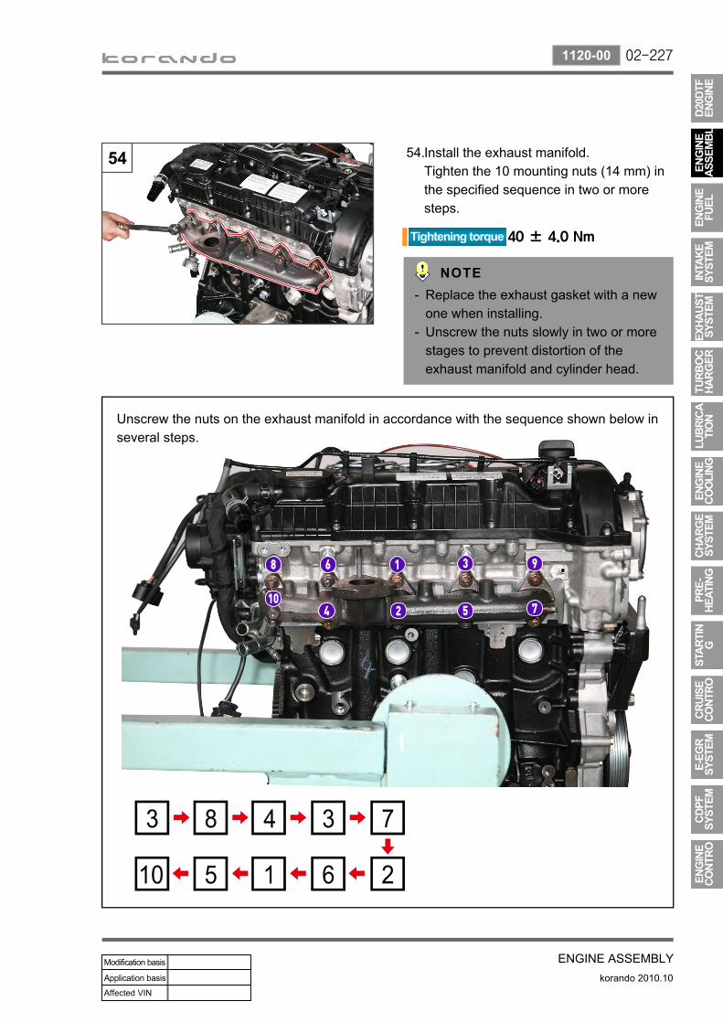
02-227
ENGINE ASSEMBLYkorando 2010.10
1120-00
Unscrew the nuts on the exhaust manifold in accordance with the sequence shown below in several steps.
Install the exhaust manifold.Tighten the 10 mounting nuts (14 mm) in the specified sequence in two or more steps.
54.
Replace the exhaust gasket with a new one when installing.Unscrew the nuts slowly in two or more stages to prevent distortion of the exhaust manifold and cylinder head.
-
-

02-228
korando 2010.10
1120-00
ENGINE ASSEMBLY
Install the exhaust protector cover.Tighten the 3 hexagon bolts (14 mm) to the specified torque.
55.
Install the engine hanger bracket.Tighten the two bolts (14 mm) to the specified torque.
56.
Install the turbocharger.Tighten the turbocharger bolt (A, 13 mm) and two nuts (B, 13 mm) to the specified torque.
57.
A B
Replace the 3-hole exhaust gasket with a new one when installing.Part number: 6710910180

02-229
ENGINE ASSEMBLYkorando 2010.10
1120-00
Install the turbocharger support bar.Tighten the bolt (A, 12 mm) on the turbocharger to the specified torque.Tighten the bolt (B, 13 mm) on the cylinder block to the specified torque.
58.
Install the turbocharger oil supply and return pipes.
59.
Connect the oil supply pipe.a.
Tighten the oil supply pipe screw fitting (A) on the cylinder block to the specified torque.Tighten the hollow bolt (B) for the oil supply pipe to the specified torque.
-
-
Connect the oil return pipe.b.
Tighten the bolts C and D to the specified torque.
-
Replace the gasket and copper washer with new ones.Part No.: 9777110140
Replace the gasket with a new one.Part No.: 6651870080Part No.: 6611863080

02-230
korando 2010.10
1120-00
ENGINE ASSEMBLY
Install the power steering pump.Tighten the 3 mounting bolts (13 mm) to the specified torque.
60.
Install the alternator. Tighten the mounting bolt A (17 mm) and B (15 mm) to the specified torque.
61.
Tighten the 4 mounting bolts (13 mm) for A/C compressor to the specified torque.
62.

02-231
ENGINE ASSEMBLYkorando 2010.10
1120-00
Install the idler pulley No. 1Tighten the mounting bolt (T50) to the specified torque.
63.
Install the idler pulley No. 2Tighten the mounting bolt (T50) to the specified torque.
64.
Install the fan belt auto tensioner.Tighten the mounting bolt A (17 mm) and B (14 mm) to the specified torque.
65.
Fit the belt.66.
Turn the belt tensioner tension release bolt counterclockwise to compress the tensioner and install the fan belt.
-