![Leaflet - Automatic transfer switch controllers ATL seriesmedia.klinkmann.fi/pdf/fi/lovato/lovato_PD39GB09_09.pdf · 2010-08-20 · per package [kg] Automatic transfer switch controllers](https://static.fdocuments.in/doc/165x107/5f0364517e708231d408fc63/leaflet-automatic-transfer-switch-controllers-atl-2010-08-20-per-package-kg.jpg)
Engine and generator controllers - Lovato Electric
16
Engine and generator controllers
Transcript of Engine and generator controllers - Lovato Electric
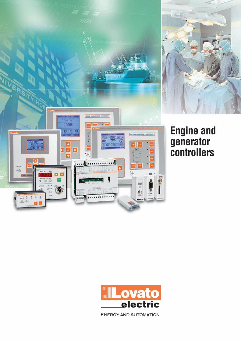
Engine andgeneratorcontrollers
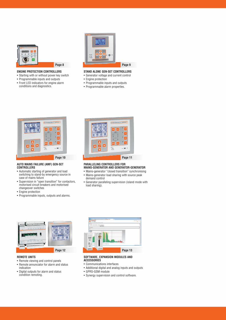
ENGINE PROTECTION CONTROLLERS• Starting with or without power key switch • Programmable inputs and outputs • Front LED indicators for engine alarm
conditions and diagnostics.
STAND ALONE GEN-SET CONTROLLERS• Generator voltage and current control • Engine protection • Programmable inputs and outputs • Programmable alarm properties.
AUTO MAINS FAILURE (AMF) GEN-SETCONTROLLERS• Automatic starting of generator and load
switching to stand-by emergency source incase of mains failure
• Supervision in “open transition” for contactors,motorised circuit breakers and motorisedchangeover switches
• Engine protection • Programmable inputs, outputs and alarms.
PARALLELING CONTROLLERS FOR MAINS-GENERATOR AND GENERATOR-GENERATOR • Mains-generator “closed transition” synchronising • Mains-generator load sharing with source peak
demand control • Generator paralleling supervision (island mode with
load sharing).
REMOTE UNITS • Remote viewing and control panels • Remote annunciator for alarm and status
indication • Digital outputs for alarm and status
condition remoting.
SOFTWARE, EXPANSION MODULES ANDACCESSORIES• Communications interfaces• Additional digital and analog inputs and outputs • GPRS-GSM module• Synergy supervision and control software.
Page 8 Page 9
Page 10 Page 11
Page 12 Page 13

PAGEEngine and generator controllers
Engine protection controllers .......................................................................................................................................... 8Stand alone gen-set controllers ....................................................................................................................................... 9Automatic mains failure (AMF) gen-set controllers ......................................................................................................... 10Paralleling controllers for mains-generator and generator-generator ............................................................................. 11Remote units .................................................................................................................................................................... 12Communication devices and expansion modules ........................................................................................................... 13Software, APP and accessories ........................................................................................................................................ 14
Dimensions ................................................................................................................. 15
EN
ER
GY
MA
NA
GE
ME
NT
Extensive selection of functions tosatisfy all application requirements Power supply range 12-24VDC foreach single product Totally programmable inputs,outputs and alarms RS232, RS485, USB, Ethernetcommunication interfaceEngine control by CANbusSetup and supervision software Modem control for sending alarmmessages and emails.

4
Engine and generator controllers
Characteristics
ENGINE PROTECTION CONTROLLERS STAND ALONE GEN-SET CONTROLLERSRGK30 RGK20 RGK40 RGK600 SA RGK700 SA RGK800 SA
RGK601 SA
Generator voltage control – L-N ❶ L1-L2-L3/N L1-L2-L3-N L1-L2-L3-N L1-L2-L3-NCurrent control – – L1 L1-L2-L3 L1-L2-L3 L1-L2-L3-NRated frequency – 50/60Hz 50/60Hz 50/60Hz 50/60Hz 50/60/400HzDigital inputs n° 4 4 6 5 7 9Digital outputs n° 2 (Relay) 3 (SSR) 1 (Relay) + 4 (SSR) 6 (SSR) 3 (Relay) +4 (SSR) 3(Relay)+6 (SSR)+1(SO)Engine running inputs “D+” and “AC” “D+” and “AC” “D+” and “AC” “D+” “D+” and “AC” “D+” and “AC”Ohmic inputs for fuel-pressure-temperature – – –Remote control – – – –CANbus interface – – – RGK601SARated battery voltage 12/24VDC 12/24VDC 12/24VDC 12/24VDC 12/24VDC 12/24VDCPower supply range 9-33VDC 9-35VDC 9-35VDC 7-33VDC 7-33VDC 7-33VDCMains voltage control – – – – – –Rated voltage range – 10-277VAC 100-415VAC 100-480VAC 30-600VAC 30-600VACVT programming – –Rated input current – – 5A 5A/1A 5A/1A 5A/1ATRMS voltage measurement – –TRMS current measurement – –Display – 7 digit LCD 4-digit LCD Graphic backlit Graphic backlit Graphic backlit
LCD, LCD, LCD,128x80 pixels 128x80 pixels 128x80 pixels
Engine running magnetic pick-up input – – – RGK600SAEngine speed input “W” “W” or generator “W” or generator “W” or generator “W” or generator “W” or generator
frequency frequency frequency or frequency frequency“Pick-up” (RGK600SA) or “Pick-up” or “Pick-up”
Auxiliary analog input – – – – –I/O expansion – – – RGK RR RGK RR 3 x EXP... + RGK RRUSB/Optical port on front – – –Wi-Fi port on front – – –USB port at rear – – – – – EXP1010Ethernet port with Web server function – – – – – EXP1013GPRS/GSM modem – – – – – EXP1015RS232 serial port – (TTL) (TTL) – EXP1011RS485 serial port – – – – –Event logging – – –RTC (Real Time Clock) – – – – –Programmable Inputs/Outputs –PLC logic function – – – –Alarms n° 6 13 25 59 60 60User alarms n° – 1 1 4 8 8Alarm property customising –Texts for alarms, events and parameters – – –Multilanguage (type) n° – – – 5 (GB - I - F - P - E)∑ 5 (GB - I - F - P - E)∑ 5 (GB - I - F - P - E)∑Upload languages – – –Load sharing – – – – – –Generator paralleling – – – – – –Mains-generator synchronising – – – – – –(closed transition) IEC front degree of protection IP41 IP41 IP54 IP54 ∏ IP65 IP65Certifications cULus, GOST TR-CU cULus, GOST TR-CU cULus, GOST TR-CU cULus pending cULus, GOST TR-CU cULus, GOST TR-CU
❶ Frequency only.∑ Controller uploading of other mutilanguage sets. ∏ IP65 with optional gasket.
5
Engine and generator controllers
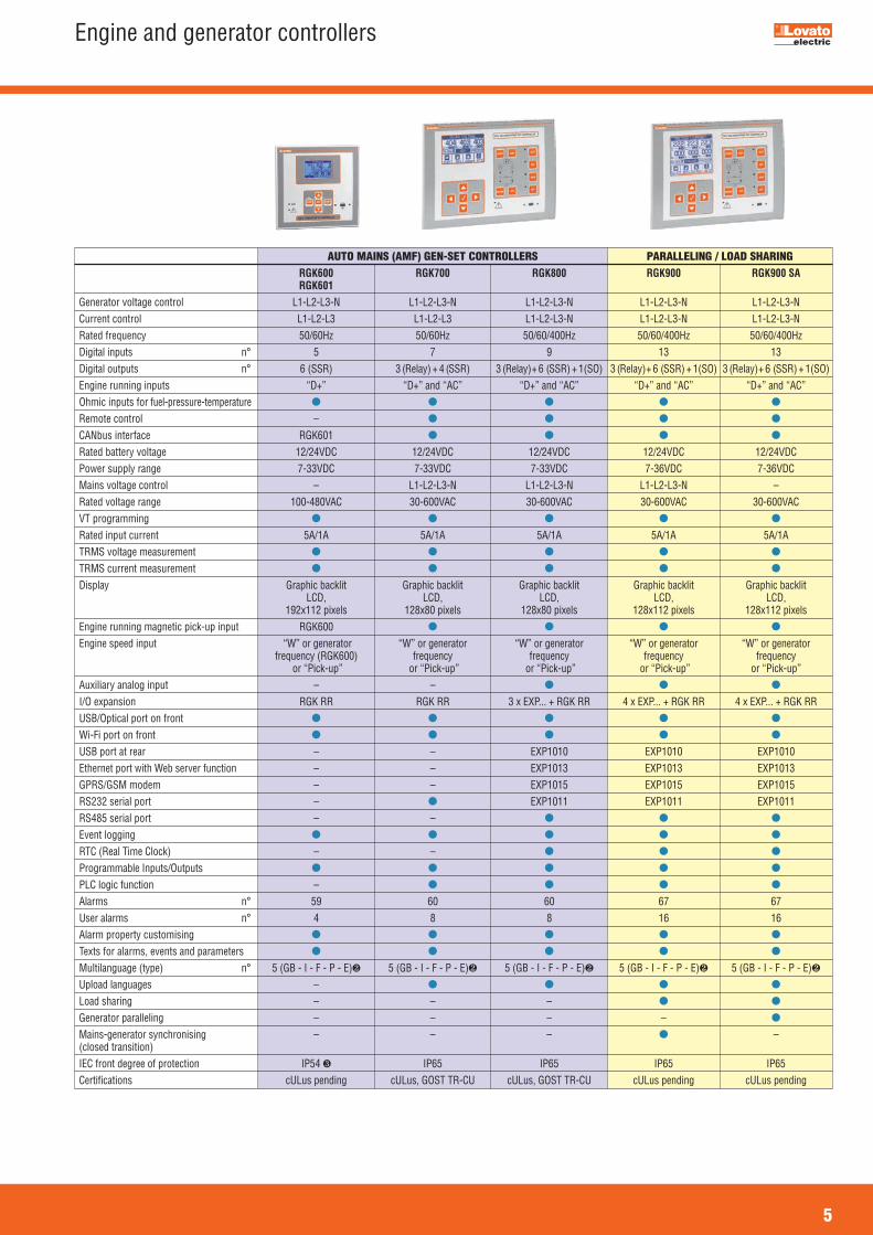
AUTO MAINS (AMF) GEN-SET CONTROLLERS PARALLELING / LOAD SHARINGRGK600 RGK700 RGK800 RGK900 RGK900 SARGK601
Generator voltage control L1-L2-L3-N L1-L2-L3-N L1-L2-L3-N L1-L2-L3-N L1-L2-L3-NCurrent control L1-L2-L3 L1-L2-L3 L1-L2-L3-N L1-L2-L3-N L1-L2-L3-NRated frequency 50/60Hz 50/60Hz 50/60/400Hz 50/60/400Hz 50/60/400HzDigital inputs n° 5 7 9 13 13Digital outputs n° 6 (SSR) 3 (Relay) +4 (SSR) 3 (Relay) + 6 (SSR)+1(SO) 3 (Relay) + 6 (SSR)+1(SO) 3 (Relay) + 6 (SSR)+1(SO)Engine running inputs “D+” “D+” and “AC” “D+” and “AC” “D+” and “AC” “D+” and “AC”Ohmic inputs for fuel-pressure-temperature Remote control –CANbus interface RGK601Rated battery voltage 12/24VDC 12/24VDC 12/24VDC 12/24VDC 12/24VDCPower supply range 7-33VDC 7-33VDC 7-33VDC 7-36VDC 7-36VDCMains voltage control – L1-L2-L3-N L1-L2-L3-N L1-L2-L3-N –Rated voltage range 100-480VAC 30-600VAC 30-600VAC 30-600VAC 30-600VACVT programmingRated input current 5A/1A 5A/1A 5A/1A 5A/1A 5A/1ATRMS voltage measurementTRMS current measurementDisplay Graphic backlit Graphic backlit Graphic backlit Graphic backlit Graphic backlit
LCD, LCD, LCD, LCD, LCD,192x112 pixels 128x80 pixels 128x80 pixels 128x112 pixels 128x112 pixels
Engine running magnetic pick-up input RGK600Engine speed input “W” or generator “W” or generator “W” or generator “W” or generator “W” or generator
frequency (RGK600) frequency frequency frequency frequencyor “Pick-up” or “Pick-up” or “Pick-up” or “Pick-up” or “Pick-up”
Auxiliary analog input – –I/O expansion RGK RR RGK RR 3 x EXP... + RGK RR 4 x EXP... + RGK RR 4 x EXP... + RGK RRUSB/Optical port on frontWi-Fi port on front USB port at rear – – EXP1010 EXP1010 EXP1010Ethernet port with Web server function – – EXP1013 EXP1013 EXP1013GPRS/GSM modem – – EXP1015 EXP1015 EXP1015RS232 serial port – EXP1011 EXP1011 EXP1011RS485 serial port – –Event loggingRTC (Real Time Clock) – –Programmable Inputs/OutputsPLC logic function –Alarms n° 59 60 60 67 67User alarms n° 4 8 8 16 16Alarm property customisingTexts for alarms, events and parametersMultilanguage (type) n° 5 (GB - I - F - P - E)∑ 5 (GB - I - F - P - E)∑ 5 (GB - I - F - P - E)∑ 5 (GB - I - F - P - E)∑ 5 (GB - I - F - P - E)∑Upload languages –Load sharing – – –Generator paralleling – – – –Mains-generator synchronising – – – –(closed transition) IEC front degree of protection IP54 ∏ IP65 IP65 IP65 IP65Certifications cULus pending cULus, GOST TR-CU cULus, GOST TR-CU cULus pending cULus pending
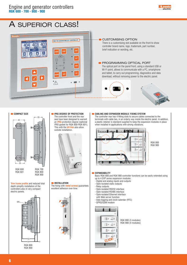
PROGRAMMING OPTICAL PORT The optical port on the panel front, using a standard USB orWi-Fi point, allows to communicate with a PC, smartphoneand tablet, to carry out programming, diagnostics and datadownload, without removing power to the electric panel.
6
Engine and generator controllersRGK 600 - 700 - 800 - 900
CABLING AND EXPANSION MODULE FIXING SYSTEM The controller rear has 4 fitting slots to secure cables connected to the
terminals with cable ties, in an orderly way inside the electric panel. In addition,a plastic retainer is standard supplied to keep the expansion modules in placewhen installed in applications with strong vibrations.
A SUPERIOR CLASS!
CUSTOMISING OPTIONThere is a customising slot available on the front to showcontroller brand name, logo, trademark, part number,brief indication or wording, etc.
COMPACT SIZE
Trim frame profile and reduced totaldepth simplify installation of thecontrollers also in very compactelectric panels.
56
59 12
157
EXP...
IP65 DEGREE OF PROTECTION The controller front and the rear
seal have been designed to warrantan IP65 protection degree (optionalIP65 gasket for RGK 600-RGK 601).This with the UV film also allowoutside installation.
INSTALLATIONThe fixing with metal screws guaranteesexcellent adhesion over time.
EXPANDABILITY Basic RGK 800 and RGK 900 controller functions can be easily extended using
up to 4 EXP series expansion modules: - Digital and analog inputs and outputs
- Opto-isolated static outputs - Relay outputs - Opto-isolated RS232 interface - Opto-isolated RS485 interface - Opto-isolated Ethernet interface
with Web server function - Data logging and clock-calendar (RTC) - GPRS/GSM modem
CLICK!
3343
35
RGK 600RGK 601
RGK 700RGK 800RGK 900
RGK 800 (3 modules)RGK 900 (4 modules)
RGK 800RGK 900
RGK 800RGK 900

GPRS/GSM MODEM
Once a data-enabled SIM card isinserted, RGK 800 - RGK 900controllers can send SMS and emailmessages with alarm and eventconditions as well as the latest loggedevents to a FTP server.
OPTO-ISOLATED ETHERNET INTERFACEWITH WEB SERVER FUNCTION
Web Browsing of the single controllerconnected in Ethernet by EXP10 13expansion module.
CANBUS COMMUNICATION PORT Most models are standard equipped
with CAN-J1939 communicationport.
7
Engine and generator controllersRGK 600 - 700 - 800 - 900
PLC FUNCTION
Capability to combine togetherinternal status of controllers withsignals incoming from the field toactivate outputs and generate alarms.
LOAD MANAGEMENT There are different methods of
controlling the load conditions; eachcontroller has special parametersfunctions as follows:
- RGK 600 - RGK 700 - RGK800 types: load shedding and dummy
load modes - RGK 900 types: base-load and peak shaving modes.
PARALLELING RGK 900 and RGK 900SA
controllers can control theswitching between the mains andgenerators without having to switchoff the power supply to the load. In addition, they can control theparalleling connection of two ormore generators sharing in this waythe load on more than one source.
The RGK 900MC can control andsynchronise mains paralleloperation with a power buscomposed by a series of generatingsets.
REMOTE UNITS
Remote displays panels
There are “mirror” display unitsavailable to remotely operate as if infront of the generating set.
Remote annunciator
A remote display can view alarmconditions and can be operated forsilencing them.
Alarm-state relay unit The relay unit allows to transmit, on
volt-free contacts, the status andalarms of RGK... controllers.
SUPERVISION SOFTWARE is web-based and provides
for an easy and efficient way tomonitor and control electricalinstallations as well as fieldequipment. It can be used to controlthe generator status for:
- Graphic display of allmeasurements
- Viewing data and charts - Overall view of alarm status - Input-output status - Remote control - Capability to simultaneously
supervise more than one generator - Automatic function to send emails.
With this versatile system, the usercan parameterise controllers, getdata-log files and commandscarried out, compile graphic pagesand charts and implement accesslevel management.
Server-multiclient system based onMS SQL RDBMS with web-browserinterface.Simultaneous management ofdifferent communication channelswith independent configuration(protocols, speed rate, RS232,RS485, Ethernet, modem).
EXPANDABILITYAn extensive selection of modules is available to increase thecontroller functionity.
GPRS/GSM MODEMAmong the expansion modules, there is a GPRS/GSM modem,automatically configured by genset controller.
MAINTENANCE Maintenance supervision at programmed intervals.
STREAMLINE DESIGN The controller has an ergonomic design and, at the sametime, particular care has been given to minimum detailaesthetics.

8Accessoriespage 14
Dimensionspage 15
Engine and generator controllers
General characteristics for RGK 30OPERATOR INTERFACE– 2 programming key buttons– 1 LED indicator for engine status– 1 LED indicator for glow plug pre-heating– 5 LED indicators for alarm status– Remote starting only.
INPUTS/OUTPUTS– Digital inputs: 3 negative and 1 positive
(start/stop by remote key switch)– Digital outputs: 2 relay (1 programmable).
Certifications and complianceCertifications obtained: UL Listed, for USA and Canada(cULus-File E93601), as Auxiliary Devices-Generatorcontrollers; GOST TR-CU.Compliant with standards: IEC/EN 61010-1, IEC/EN 61000-6-2, EN 55011, UL 508, CSA C22.2 n° 14.
General characteristics for RGK 20OPERATOR INTERFACE– 1 ON-OFF power supply key selector switch– 1 semi-automatic engine START button– 2 programmable key buttons– 7 digit LCD display (Hours, Hz, VBatt)– 1 LED indicator for engine status– 1 LED indicator for glow plug pre-heating– 5 LED indicators for alarm status– Local or remote starting.
INPUTS/OUTPUTS Programmable functions:– Generator frequency input– Digital inputs: 3 negative and 1 positive– Digital outputs: 3 static (1 programmable) – Inputs, outputs and alarms, all with programmable
properties.
ADDITIONAL FEATURES– Quick set-up with PC software (TTL/RS232 serial
port).
Certifications and complianceCertifications obtained: UL Listed, for USA and Canada(cULus-File E93601), as Auxiliary Devices-Generatorcontrollers; GOST TR-CU.Compliant with standards: IEC/EN 61010-1, IEC/EN 61000-6-2, IEC/EN 61000-6-3, UL 508, CSA C22.2 n° 14.
Order code Description Qty Wt per pkg n° [kg] RGK 30 12/24VDC for external 1 0.160 start-stop key switch RGK 20 12/24VDC, built-in power 1 0.270 supply key switch, with TTL programming port
Engine protectioncontrollers
RGK 20
RGK 30
9Communications-expansionpages 12 and 13
Software and accessoriespage 14
Dimensionspage 15
Engine and generator controllers
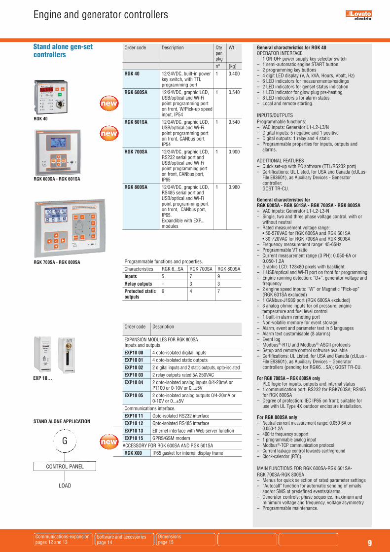
General characteristics for RGK 40 OPERATOR INTERFACE– 1 ON-OFF power supply key selector switch– 1 semi-automatic engine START button– 2 programming key buttons– 4 digit LED display (V, A, kVA, Hours, Vbatt, Hz)– 6 LED indicators for measurements/readings– 2 LED indicators for genset status indication– 1 LED indicator for glow plug pre-heating– 8 LED indicators s for alarm status– Local and remote starting.
INPUTS/OUTPUTS Programmable functions:– VAC inputs: Generator L1-L2-L3/N – Digital inputs: 5 negative and 1 positive– Digital outputs: 1 relay and 4 static– Programmable properties for inputs, outputs and
alarms.
ADDITIONAL FEATURES– Quick set-up with PC software (TTL/RS232 port)– Certifications: UL Listed, for USA and Canada (cULus-
File E93601), as Auxiliary Devices - Generatorcontroller; GOST TR-CU.
General characteristics for RGK 600SA - RGK 601SA - RGK 700SA - RGK 800SA– VAC inputs: Generator L1-L2-L3-N– Single, two and three phase voltage control, with or
without neutral– Rated measurement voltage range: • 50-576VAC for RGK 600SA and RGK 601SA • 30-720VAC for RGK 700SA and RGK 800SA– Frequency measurement range: 45-65Hz– Programmable VT ratio– Current measurement range (3 PH): 0.050-6A or
0.050-1.2A– Graphic LCD: 128x80 pixels with backlight– 1 USB/optical and Wi-Fi port on front for programming– Engine running detection: “D+”, generator voltage and
frequency– 2 engine speed inputs: “W” or Magnetic “Pick-up”
(RGK 601SA excluded)– 1 CANbus-J1939 port (RGK 600SA excluded)– 3 analog ohmic inputs for oil pressure, engine
temperature and fuel level control – 1 built-in alarm remoting port– Non-volatile memory for event storage– Alarm, event and parameter text in 5 languages – Alarm text customisable (8 alarms)– Event log– Modbus®-RTU and Modbus®-ASCII protocols– Setup and remote control software available– Certifications: UL Listed, for USA and Canada (cULus -
File E93601), as Auxiliary Devices – Generatorcontrollers (pending for RGK6…SA); GOST TR-CU.
For RGK 700SA – RGK 800SA only– PLC logic for inputs, outputs and internal status– 1 communication port: RS232 for RGK700SA; RS485
for RGK 800SA– Degree of protection: IEC IP65 on front; suitable for
use with UL Type 4X outdoor enclosure installation.
For RGK 800SA only– Neutral current measurement range: 0.050-6A or
0.050-1.2A– 400Hz frequency support – 1 programmable analog input– Modbus®-TCP communication protocol– Current leakage control towards earth/ground – Clock-calendar (RTC).
MAIN FUNCTIONS FOR RGK 600SA-RGK 601SA-RGK 700SA-RGK 800SA– Menus for quick selection of rated parameter settings– “Autocall” function for automatic sending of emails
and/or SMS at predefined events/alarms– Generator controls: phase sequence, maximum and
minimum voltage and frequency, voltage asymmetry– Programmable maintenance.
Order code Description Qty Wt per pkg n° [kg] RGK 40 12/24VDC, built-in power 1 0.400 key switch, with TTL programming port RGK 600SA 12/24VDC, graphic LCD, 1 0.540 USB/optical and Wi-Fi point programming port on front, W/Pick-up speed input, IP54 RGK 601SA 12/24VDC, graphic LCD, 1 0.540 USB/optical and Wi-Fi point programming port on front, CANbus port, IP54 RGK 700SA 12/24VDC, graphic LCD, 1 0.900 RS232 serial port and USB/optical and Wi-Fi point programming port on front, CANbus port, IP65 RGK 800SA 12/24VDC, graphic LCD, 1 0.980 RS485 serial port and USB/optical and Wi-Fi point programming port on front, CANbus port, IP65. Expandible with EXP... modules
Programmable functions and properties. Characteristics RGK 6...SA RGK 700SA RGK 800SA Inputs 5 7 9 Relay outputs – 3 3 Protected static 6 4 7 outputs
Stand alone gen-setcontrollers
RGK 40
RGK 600SA - RGK 601SA
RGK 700SA - RGK 800SA
Order code Description EXPANSION MODULES FOR RGK 800SA Inputs and outputs. EXP10 00 4 opto-isolated digital inputs EXP10 01 4 opto-isolated static outputs EXP10 02 2 digital inputs and 2 static outputs, opto-isolated EXP10 03 2 relay outputs rated 5A 250VAC EXP10 04 2 opto-isolated analog inputs 0/4-20mA or PT100 or 0-10V or 0...±5V EXP10 05 2 opto-isolated analog outputs 0/4-20mA or 0-10V or 0...±5V Communications interface. EXP10 11 Opto-isolated RS232 interface EXP10 12 Opto-isolated RS485 interface EXP10 13 Ethernet interface with Web server function EXP10 15 GPRS/GSM modemACCESSORY FOR RGK 600SA AND RGK 601SA RGK X00 IP65 gasket for internal display frame
STAND ALONE APPLICATION
LOAD
G
CONTROL PANEL
EXP 10...
10Communications-expansionpages 12 and 13
Software and accessoriespage 14
Dimensionspage 15
Engine and generator controllers
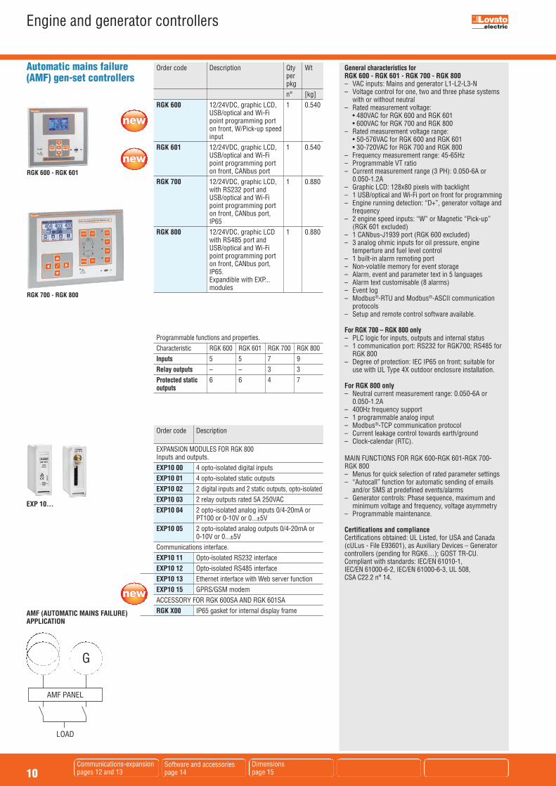
General characteristics forRGK 600 - RGK 601 - RGK 700 - RGK 800 – VAC inputs: Mains and generator L1-L2-L3-N– Voltage control for one, two and three phase systems
with or without neutral – Rated measurement voltage: • 480VAC for RGK 600 and RGK 601 • 600VAC for RGK 700 and RGK 800– Rated measurement voltage range: • 50-576VAC for RGK 600 and RGK 601 • 30-720VAC for RGK 700 and RGK 800– Frequency measurement range: 45-65Hz– Programmable VT ratio– Current measurement range (3 PH): 0.050-6A or
0.050-1.2A– Graphic LCD: 128x80 pixels with backlight– 1 USB/optical and Wi-Fi port on front for programming– Engine running detection: “D+”, generator voltage and
frequency– 2 engine speed inputs: “W” or Magnetic “Pick-up”
(RGK 601 excluded)– 1 CANbus-J1939 port (RGK 600 excluded)– 3 analog ohmic inputs for oil pressure, engine
temperture and fuel level control– 1 built-in alarm remoting port– Non-volatile memory for event storage– Alarm, event and parameter text in 5 languages – Alarm text customisable (8 alarms)– Event log– Modbus®-RTU and Modbus®-ASCII communication
protocols– Setup and remote control software available.
For RGK 700 – RGK 800 only– PLC logic for inputs, outputs and internal status– 1 communication port: RS232 for RGK700; RS485 for
RGK 800– Degree of protection: IEC IP65 on front; suitable for
use with UL Type 4X outdoor enclosure installation.
For RGK 800 only– Neutral current measurement range: 0.050-6A or
0.050-1.2A– 400Hz frequency support – 1 programmable analog input– Modbus®-TCP communication protocol– Current leakage control towards earth/ground – Clock-calendar (RTC).
MAIN FUNCTIONS FOR RGK 600-RGK 601-RGK 700-RGK 800– Menus for quick selection of rated parameter settings– “Autocall” function for automatic sending of emails
and/or SMS at predefined events/alarms– Generator controls: Phase sequence, maximum and
minimum voltage and frequency, voltage asymmetry– Programmable maintenance.
Certifications and complianceCertifications obtained: UL Listed, for USA and Canada(cULus - File E93601), as Auxiliary Devices – Generatorcontrollers (pending for RGK6…); GOST TR-CU.Compliant with standards: IEC/EN 61010-1, IEC/EN 61000-6-2, IEC/EN 61000-6-3, UL 508, CSA C22.2 n° 14.
Order code Description Qty Wt per pkg n° [kg] RGK 600 12/24VDC, graphic LCD, 1 0.540 USB/optical and Wi-Fi point programming port on front, W/Pick-up speed input RGK 601 12/24VDC, graphic LCD, 1 0.540 USB/optical and Wi-Fi point programming port on front, CANbus port RGK 700 12/24VDC, graphic LCD, 1 0.880 with RS232 port and USB/optical and Wi-Fi point programming port on front, CANbus port, IP65 RGK 800 12/24VDC, graphic LCD 1 0.880 with RS485 port and USB/optical and Wi-Fi point programming port on front, CANbus port, IP65. Expandible with EXP... modules
Automatic mains failure(AMF) gen-set controllers
Programmable functions and properties. Characteristic RGK 600 RGK 601 RGK 700 RGK 800
Inputs 5 5 7 9
Relay outputs – – 3 3
Protected static 6 6 4 7 outputs
AMF (AUTOMATIC MAINS FAILURE)APPLICATION
LOAD
G
AMF PANEL
Order code Description EXPANSION MODULES FOR RGK 800 Inputs and outputs. EXP10 00 4 opto-isolated digital inputs EXP10 01 4 opto-isolated static outputs EXP10 02 2 digital inputs and 2 static outputs, opto-isolated EXP10 03 2 relay outputs rated 5A 250VAC EXP10 04 2 opto-isolated analog inputs 0/4-20mA or PT100 or 0-10V or 0...±5V EXP10 05 2 opto-isolated analog outputs 0/4-20mA or 0-10V or 0...±5V Communications interface. EXP10 11 Opto-isolated RS232 interface EXP10 12 Opto-isolated RS485 interface EXP10 13 Ethernet interface with Web server function EXP10 15 GPRS/GSM modem ACCESSORY FOR RGK 600SA AND RGK 601SA RGK X00 IP65 gasket for internal display frame
RGK 700 - RGK 800
RGK 600 - RGK 601
EXP 10...
11Communications-expansionpages 12 and 13
Software and accessoriespage 14
Dimensionspage 15
Engine and generator controllers
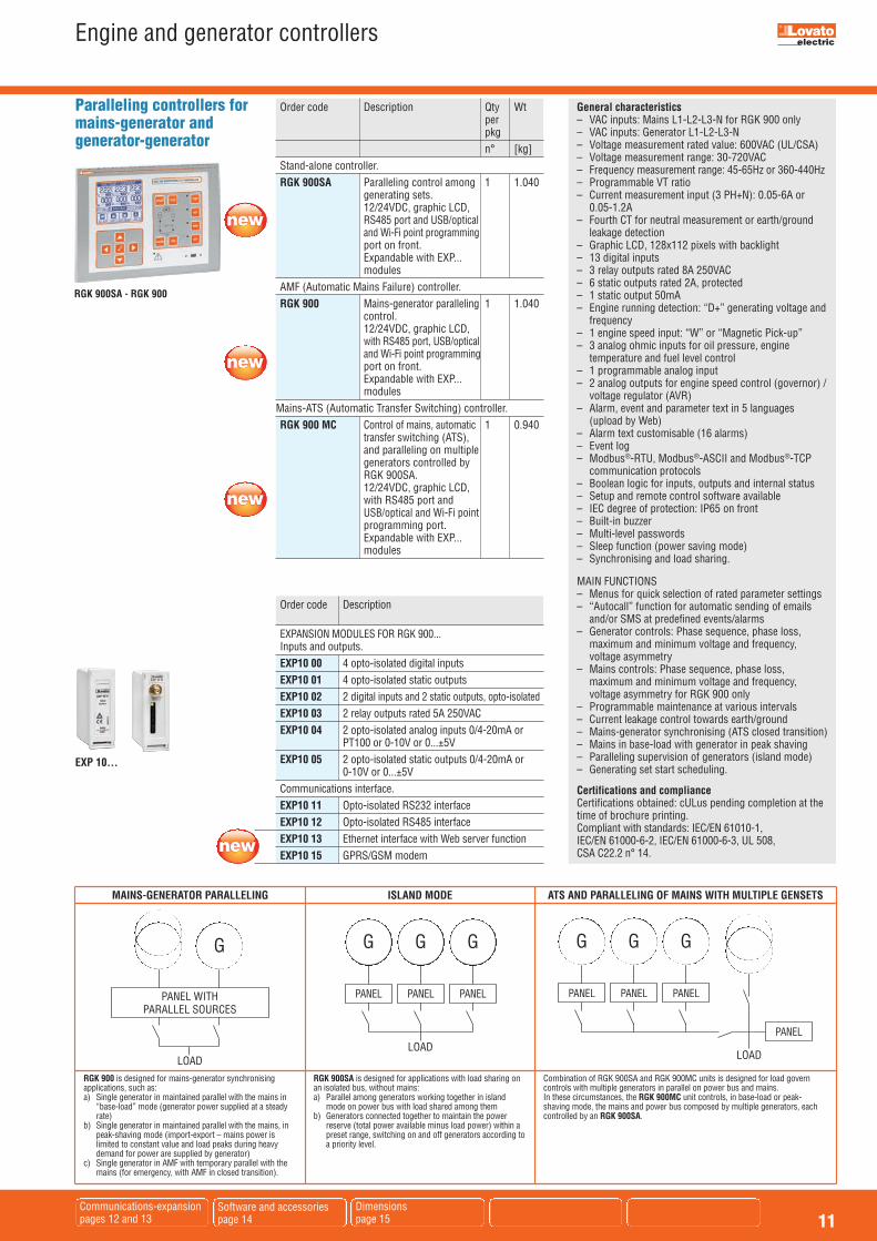
General characteristics– VAC inputs: Mains L1-L2-L3-N for RGK 900 only– VAC inputs: Generator L1-L2-L3-N– Voltage measurement rated value: 600VAC (UL/CSA)– Voltage measurement range: 30-720VAC– Frequency measurement range: 45-65Hz or 360-440Hz– Programmable VT ratio– Current measurement input (3 PH+N): 0.05-6A or
0.05-1.2A– Fourth CT for neutral measurement or earth/ground
leakage detection – Graphic LCD, 128x112 pixels with backlight – 13 digital inputs – 3 relay outputs rated 8A 250VAC– 6 static outputs rated 2A, protected – 1 static output 50mA– Engine running detection: “D+” generating voltage and
frequency– 1 engine speed input: “W” or “Magnetic Pick-up”– 3 analog ohmic inputs for oil pressure, engine
temperature and fuel level control – 1 programmable analog input – 2 analog outputs for engine speed control (governor) /
voltage regulator (AVR)– Alarm, event and parameter text in 5 languages
(upload by Web) – Alarm text customisable (16 alarms)– Event log– Modbus®-RTU, Modbus®-ASCII and Modbus®-TCP
communication protocols – Boolean logic for inputs, outputs and internal status – Setup and remote control software available – IEC degree of protection: IP65 on front– Built-in buzzer– Multi-level passwords– Sleep function (power saving mode)– Synchronising and load sharing.
MAIN FUNCTIONS– Menus for quick selection of rated parameter settings– “Autocall” function for automatic sending of emails
and/or SMS at predefined events/alarms– Generator controls: Phase sequence, phase loss,
maximum and minimum voltage and frequency,voltage asymmetry
– Mains controls: Phase sequence, phase loss,maximum and minimum voltage and frequency,voltage asymmetry for RGK 900 only
– Programmable maintenance at various intervals– Current leakage control towards earth/ground – Mains-generator synchronising (ATS closed transition)– Mains in base-load with generator in peak shaving – Paralleling supervision of generators (island mode)– Generating set start scheduling.
Certifications and complianceCertifications obtained: cULus pending completion at thetime of brochure printing.Compliant with standards: IEC/EN 61010-1, IEC/EN 61000-6-2, IEC/EN 61000-6-3, UL 508, CSA C22.2 n° 14.
Order code Description Qty Wt per pkg n° [kg] Stand-alone controller. RGK 900SA Paralleling control among 1 1.040 generating sets. 12/24VDC, graphic LCD, RS485 port and USB/optical and Wi-Fi point programming port on front. Expandable with EXP... modules AMF (Automatic Mains Failure) controller. RGK 900 Mains-generator paralleling 1 1.040 control. 12/24VDC, graphic LCD, with RS485 port, USB/optical and Wi-Fi point programming port on front. Expandable with EXP... modulesMains-ATS (Automatic Transfer Switching) controller. RGK 900 MC Control of mains, automatic 1 0.940 transfer switching (ATS), and paralleling on multiple generators controlled by RGK 900SA. 12/24VDC, graphic LCD, with RS485 port and USB/optical and Wi-Fi point programming port. Expandable with EXP... modules
Paralleling controllers formains-generator andgenerator-generator
MAINS-GENERATOR PARALLELING
LOAD
G
PANEL WITH PARALLEL SOURCES
ISLAND MODE
G
PANEL
G
PANEL
G
PANEL
LOAD
ATS AND PARALLELING OF MAINS WITH MULTIPLE GENSETS
G
PANEL
G
PANEL
G
PANEL
LOAD
Order code Description EXPANSION MODULES FOR RGK 900... Inputs and outputs. EXP10 00 4 opto-isolated digital inputs EXP10 01 4 opto-isolated static outputs EXP10 02 2 digital inputs and 2 static outputs, opto-isolated EXP10 03 2 relay outputs rated 5A 250VAC EXP10 04 2 opto-isolated analog inputs 0/4-20mA or PT100 or 0-10V or 0...±5V EXP10 05 2 opto-isolated static outputs 0/4-20mA or 0-10V or 0...±5V Communications interface. EXP10 11 Opto-isolated RS232 interface EXP10 12 Opto-isolated RS485 interface EXP10 13 Ethernet interface with Web server function EXP10 15 GPRS/GSM modem
RGK 900SA - RGK 900
PANEL
EXP 10...
RGK 900 is designed for mains-generator synchronisingapplications, such as:a) Single generator in maintained parallel with the mains in
“base-load” mode (generator power supplied at a steadyrate)
b) Single generator in maintained parallel with the mains, inpeak-shaving mode (import-export – mains power islimited to constant value and load peaks during heavydemand for power are supplied by generator)
c) Single generator in AMF with temporary parallel with themains (for emergency, with AMF in closed transition).
RGK 900SA is designed for applications with load sharing onan isolated bus, without mains:a) Parallel among generators working together in island
mode on power bus with load shared among themb) Generators connected together to maintain the power
reserve (total power available minus load power) within apreset range, switching on and off generators according toa priority level.
Combination of RGK 900SA and RGK 900MC units is designed for load governcontrols with multiple generators in parallel on power bus and mains.In these circumstances, the RGK 900MC unit controls, in base-load or peak-shaving mode, the mains and power bus composed by multiple generators, eachcontrolled by an RGK 900SA.
12Communicationspage 13
Software and accessoriespage 14
Dimensionspage 15
Engine and generator controllers
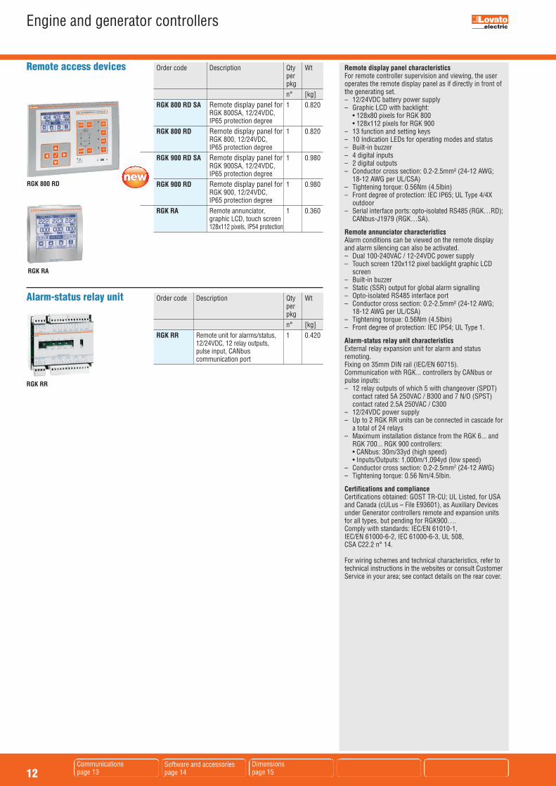
Remote display panel characteristicsFor remote controller supervision and viewing, the useroperates the remote display panel as if directly in front ofthe generating set. – 12/24VDC battery power supply– Graphic LCD with backlight: • 128x80 pixels for RGK 800 • 128x112 pixels for RGK 900– 13 function and setting keys– 10 Indication LEDs for operating modes and status– Built-in buzzer– 4 digital inputs– 2 digital outputs– Conductor cross section: 0.2-2.5mm² (24-12 AWG;
18-12 AWG per UL/CSA)– Tightening torque: 0.56Nm (4.5lbin)– Front degree of protection: IEC IP65; UL Type 4/4X
outdoor– Serial interface ports: opto-isolated RS485 (RGK…RD);
CANbus-J1979 (RGK…SA).
Remote annunciator characteristicsAlarm conditions can be viewed on the remote displayand alarm silencing can also be activated. – Dual 100-240VAC / 12-24VDC power supply– Touch screen 120x112 pixel backlight graphic LCD
screen– Built-in buzzer– Static (SSR) output for global alarm signalling– Opto-isolated RS485 interface port– Conductor cross section: 0.2-2.5mm² (24-12 AWG;
18-12 AWG per UL/CSA)– Tightening torque: 0.56Nm (4.5lbin)– Front degree of protection: IEC IP54; UL Type 1.
Alarm-status relay unit characteristicsExternal relay expansion unit for alarm and status remoting.Fixing on 35mm DIN rail (IEC/EN 60715).Communication with RGK... controllers by CANbus orpulse inputs:– 12 relay outputs of which 5 with changeover (SPDT)
contact rated 5A 250VAC / B300 and 7 N/O (SPST)contact rated 2.5A 250VAC / C300
– 12/24VDC power supply– Up to 2 RGK RR units can be connected in cascade for
a total of 24 relays – Maximum installation distance from the RGK 6... and
RGK 700... RGK 900 controllers: • CANbus: 30m/33yd (high speed) • Inputs/Outputs: 1,000m/1,094yd (low speed)– Conductor cross section: 0.2-2.5mm2 (24-12 AWG)– Tightening torque: 0.56 Nm/4.5lbin.
Certifications and complianceCertifications obtained: GOST TR-CU; UL Listed, for USAand Canada (cULus – File E93601), as Auxiliary Devicesunder Generator controllers remote and expansion unitsfor all types, but pending for RGK900….Comply with standards: IEC/EN 61010-1, IEC/EN 61000-6-2, IEC 61000-6-3, UL 508, CSA C22.2 n° 14.
For wiring schemes and technical characteristics, refer totechnical instructions in the websites or consult CustomerService in your area; see contact details on the rear cover.
Order code Description Qty Wt per pkg n° [kg] RGK 800 RD SA Remote display panel for 1 0.820 RGK 800SA, 12/24VDC, IP65 protection degree RGK 800 RD Remote display panel for 1 0.820 RGK 800, 12/24VDC, IP65 protection degree RGK 900 RD SA Remote display panel for 1 0.980 RGK 900SA, 12/24VDC, IP65 protection degree RGK 900 RD Remote display panel for 1 0.980 RGK 900, 12/24VDC, IP65 protection degree RGK RA Remote annunciator, 1 0.360 graphic LCD, touch screen 128x112 pixels, IP54 protection
Remote access devices
Order code Description Qty Wt per pkg n° [kg] RGK RR Remote unit for alarms/status, 1 0.420 12/24VDC, 12 relay outputs, pulse input, CANbus communication port
Alarm-status relay unit
RGK RA
RGK RR
RGK 800 RD
13Software and accessoriespage 14
Dimensionspage 15
Engine and generator controllers
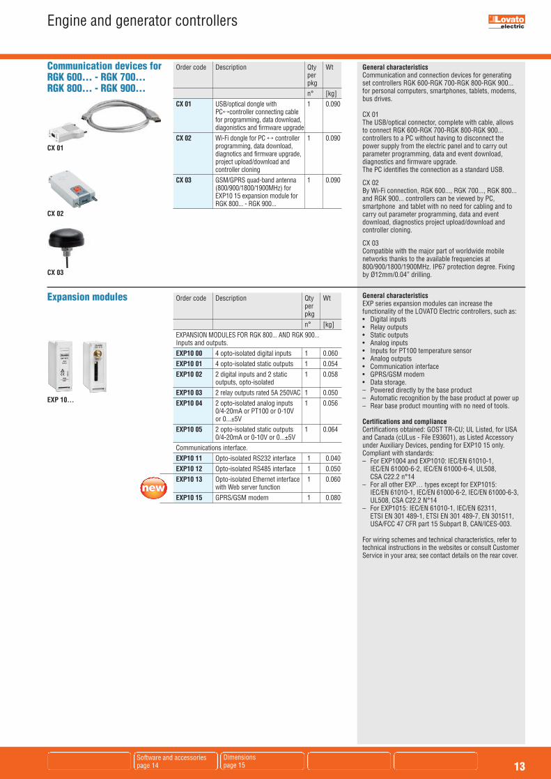
Order code Description Qty Wt per pkg n° [kg] EXPANSION MODULES FOR RGK 800... AND RGK 900... Inputs and outputs. EXP10 00 4 opto-isolated digital inputs 1 0.060 EXP10 01 4 opto-isolated static outputs 1 0.054 EXP10 02 2 digital inputs and 2 static 1 0.058 outputs, opto-isolated EXP10 03 2 relay outputs rated 5A 250VAC 1 0.050 EXP10 04 2 opto-isolated analog inputs 1 0.056 0/4-20mA or PT100 or 0-10V or 0...±5V EXP10 05 2 opto-isolated static outputs 1 0.064 0/4-20mA or 0-10V or 0...±5V Communications interface. EXP10 11 Opto-isolated RS232 interface 1 0.040 EXP10 12 Opto-isolated RS485 interface 1 0.050 EXP10 13 Opto-isolated Ethernet interface 1 0.060 with Web server function EXP10 15 GPRS/GSM modem 1 0.080
Expansion modules
General characteristicsCommunication and connection devices for generatingset controllers RGK 600-RGK 700-RGK 800-RGK 900...for personal computers, smartphones, tablets, modems,bus drives.
CX 01The USB/optical connector, complete with cable, allowsto connect RGK 600-RGK 700-RGK 800-RGK 900...controllers to a PC without having to disconnect thepower supply from the electric panel and to carry outparameter programming, data and event download,diagnostics and firmware upgrade.The PC identifies the connection as a standard USB.
CX 02By Wi-Fi connection, RGK 600..., RGK 700..., RGK 800...and RGK 900... controllers can be viewed by PC,smartphone and tablet with no need for cabling and tocarry out parameter programming, data and eventdownload, diagnostics project upload/download andcontroller cloning.
CX 03Compatible with the major part of worldwide mobilenetworks thanks to the available frequencies at800/900/1800/1900MHz. IP67 protection degree. Fixingby Ø12mm/0.04” drilling.
General characteristicsEXP series expansion modules can increase thefunctionality of the LOVATO Electric controllers, such as:• Digital inputs• Relay outputs• Static outputs• Analog inputs• Inputs for PT100 temperature sensor• Analog outputs• Communication interface• GPRS/GSM modem• Data storage.– Powered directly by the base product– Automatic recognition by the base product at power up– Rear base product mounting with no need of tools.
Certifications and complianceCertifications obtained: GOST TR-CU; UL Listed, for USAand Canada (cULus - File E93601), as Listed Accessoryunder Auxiliary Devices, pending for EXP10 15 only. Compliant with standards: – For EXP1004 and EXP1010: IEC/EN 61010-1,
IEC/EN 61000-6-2, IEC/EN 61000-6-4, UL508, CSA C22.2 n°14
– For all other EXP… types except for EXP1015: IEC/EN 61010-1, IEC/EN 61000-6-2, IEC/EN 61000-6-3,UL508, CSA C22.2 N°14
– For EXP1015: IEC/EN 61010-1, IEC/EN 62311, ETSI EN 301 489-1, ETSI EN 301 489-7, EN 301511,USA/FCC 47 CFR part 15 Subpart B, CAN/ICES-003.
For wiring schemes and technical characteristics, refer totechnical instructions in the websites or consult CustomerService in your area; see contact details on the rear cover.
EXP 10...
Communication devices forRGK 600... - RGK 700...RGK 800... - RGK 900...
Order code Description Qty Wt per pkg n° [kg] CX 01 USB/optical dongle with 1 0.090 PC÷controller connecting cable for programming, data download, diagonistics and firmware upgrade CX 02 Wi-Fi dongle for PC ÷ controller 1 0.090 programming, data download, diagnotics and firmware upgrade, project upload/download and controller cloning CX 03 GSM/GPRS quad-band antenna 1 0.090 (800/900/1800/1900MHz) for EXP10 15 expansion module for RGK 800... - RGK 900...
CX 01
CX 02
CX 03

14
Engine and generator controllers
RGK SW10
Customisation manager softwareOnce installed on a personal computer, besides setting up allfunctional parameters of the controllers, this software allowsto handle many types of data such as texts, analog sensorresponse definition (for fuel, pressure, temperature), currentoverload protection, logo or trademark display at power upand setup exit, custom information pages.The user can enable and disable alarms along with definingthe controller feedback for alarm conditions and savingprojects with the described types of files in single blocksdespite the fact that different projects can share certain files.For instance, two projects can have the same text file butdistinct sensor response files.
softwareSupervision and control web-based software designed forthe monitoring and control of all LOVATO Electric controllersequipped with communication capabilities via serial ports,Ethernet or modem. For the list of compatible devices,consult www.LovatoElectric.com.It is a highly versatile system accessible to a large number ofusers/workstations, via intranet, VPN or Internet. In additionto electrical quantities, it allows to check all environmentaland process information (operating status, alarms, etc.),acquired from LOVATO Electric products, and thereby toparameterise and carry out commands. It is capable of:– Managing multiple communication channels at the same
time– Connecting the devices to the various channels– Collecting data from all the devices and storing them in a
database– Displaying collected data in graphical pages and tables– Allowing access to the devices and their data according
to the rights of the different users.Communication features include:– Server-multiclient system with Web-browser interface– Simultaneous management of different communication
channels with independent configuration (protocols,speed rate, RS232, RS485, Ethernet, modem)
– Simple, intuitive and guided configuration, multilanguagetext, not requiring any particular computer knowledge.
APP for smartphones and tabletsThe RGK application lets the user set up controllers, sendcommands, read values, download statistics and events,email retrieved data, Wi-Fi connect the CX02 dongle with asmartphone/tablet/PC. It is compatible with iOS and Anrdroid.Consult Customer Service in your area for availability andlink details; refer to contact details on the rear cover.
For wiring schemes and technical characteristics, refer totechnical instructions in the websites or consult CustomerService in your area; see contact details on the rear cover.
Order code Description Qty Wt per pkg n° [kg] Customisation manager software. RGK SW10 Customisation manager software 1 0.246 complete with 51 C2 connecting cable
software. SYN 1 SW00 Parameter setup and data logger 1 – management software. Includes 60-day trial period of remote control supervision function (measurements, monitoring, control and Web server) SYN 1 SW11 Enable licence of supervision 1 – function (measurements, monitoring, control and Web server). Includes licence for one RGK… controller SYN 1 SW21 Enable licence of supervision 1 – function for one additional RGK… controller SYN 1 SWX00 Enable licence for sending emails 1 – and FTP function Accessories. 51 C2 PC ÷ controller connecting 1 0.090 cable, 1.8m/2yd long 51 C3 PC ÷ GSM modem connecting 1 0.210 cable, 1.8/2yd long 51 C4 PC ÷ controller RS232/RS485 1 0.147 connecting cable, 1.8m/2yd long 51 C11 PC ÷ TTL/RS232 communication 1 0.090 port connecting cable, 2.8m/3yd long 4 PX1 RS232/RS485 converter drive, 1 0.600 galvanically isolated, 220-240VAC power supply (110-120VAC on request) ❶For RGK 600…. and RGK 601… controllers. RGK X00 IP65 gasket for internal dislpay 1 0.100 frame
❶ RS232/RS485 opto-isolated converter drive, 38,400 Baud rate maximum, automatic or manual TRANSMIT line supervision, 220-240VAC ±10% (110-120VAC supply on request).
Software and accessories
51 C4
APP
SOFTWARE

15
Engine and generator controllersDimensions [mm (in)]
9(0.35")
27(1.06")
10(0.39")
72 (2.83")
72 (2
.83"
)
73.5 (2.89")68 (2.68")
68 (2
.68"
)
ENGINE PROTECTION CONTROLLERSRGK 20 Cutout
92 (3.62")
92 (3
.62"
)
96 (3
.78"
)
19(0.75")96 (3.78")
90.8
(3.5
7")
24(0.94")
REMOTE DISPLAY RGK RA Cutout
D7D7
D20D20
D9D9D8D8 D10D10
D29D29 D28D28 D19D19
D18D18 D27D27
D21D21 D30D30
D2D2
D22D22
OUT 1 OUT 2 OUT 3 OUT 4 OUT 5 OUT 6 ON
OUT 7 OUT 8 OUT 9 OUT 10 OUT 11 OUT 12 COM
TR
L H
SG
15 16 17 18
CAN
11 12 13 147 8 9 103 4 5 61 2
OUT 1 OUT 2 OUT 3 OUT 4 OUT 5 OUT 6 OUT 7
33 34 35 3629 30 31 3225 26 27 2721 22 23 2419 20
OUT 8 OUT 9 OUT 10 OUT 11 OUT 12
__ +__
SUPPLYPULSE IN
REMOTE RELAYS UNIT
+CO
M
INP
107
(4.2
1")
46.5 (1.83")
54.2 (2.13")19.8(0.78")
99.6
(3.9
2")
116 (4.57")
96 (3
.78"
)
ALARM-STATUS RELAY UNIT RGK RR
14(0.55")
6(0.24")62 (2.44")
90 (3
.54"
)
96 (3.78")92 (3.62")
92 (3
.62"
)
96 (3
.78"
)
27(1.06")
STAND-ALONE GEN-SET CONTROLLER RGK 40 Cutout
160
(6.3
0")
180
(7.0
9")
240 (9.45") 33(1.30")
56 (2.20")
59 (2.32")
157
(6.1
8")
12(0.47")
220 (8.66")
RGK 700, RGK 800RD..., RGK 900RD... excluded.
GEN-SET CONTROLLERS RGK 700... - RGK 800... - RGK 900... - REMOTE DISPLAYS PANELS RGK 800RD - RGK 800RDSA - RGK 900RD - RGK 900RDSA Cutout
144 (5.67”)
144
(5.6
7”)
43.3 (1.70”) 10(0.39”)
35(1.38”)
138 (5.43”)
138
(5.4
3”)
GEN-SET CONTROLLERS RGK 600... - RGK 601... Cutout
92 (3.62")
81 (3.19")16
(0.63")
9(0.35")
48 (1
.89"
)
45 (1
.77"
)
96 (3.78")
44 (1
.73"
)
RGK 30 Cutout
PD81
GB
10 1
3
The
prod
ucts
des
crib
ed in
thi
s pu
blicat
ion
are
subj
ect to
be
revise
d or
impr
oved
at an
y m
omen
t. Ca
talo
gue
desc
riptio
ns a
nd d
etai
ls, s
uch
as tec
hnic
al a
ndop
erat
iona
l dat
a, d
raw
ings
, diagr
ams
and
inst
ruct
ions
, etc
., do
not
hav
e an
y co
ntra
ctua
l value
. In
addi
tion,
pro
duct
s sh
ould
be
inst
alle
d an
d us
ed b
y qu
alifi
edpe
rson
nel a
nd in
com
plianc
e w
ith th
e re
gulatio
ns in
forc
e fo
r elec
trical s
yste
ms
in o
rder
to a
void
dam
ages
and
saf
ety
haza
rds.
LOVATO Electric offices in the world
LOVATO ELECTRIC S.P.A.VIA DON E. MAZZA, 12 - 24020 GORLE (BERGAMO) ITALYTel. +39 035 4282111 Fax +39 035 4282200Email: [email protected] Sales Department: Tel. +39 035 4282354 - Fax +39 035 4282400
United Kingdom LOVATO ELECTRIC LTDTel. +44 8458 110023www.Lovato.co.uk
Czech RepublicLOVATO ELECTRIC S.R.O.Tel. +420 226 203203www.LovatoElectric.cz
Germany LOVATO ELECTRIC GmbHTel. +49 7243 7669370www.LovatoElectric.de
USALOVATO ELECTRIC INCTel. +1 757 5454700www.LovatoUsa.com
SpainLOVATO ELECTRIC S.L.U.Tel. +34 93 7812016www.LovatoElectric.es
CanadaLOVATO ELECTRIC CORP.Tel. +1 450 6819200www.Lovato.ca
Poland LOVATO ELECTRIC SP. Z O.O.Tel. +48 71 7979010www.LovatoElectric.pl
ChinaLOVATO ELECTRIC (SHANGHAI) CO [email protected]
Turkey LOVATO ELEKTRİK LTDTel. +90 216 499 86 86www.LovatoElectric.com.tr
United Arab EmiratesLOVATO ELECTRIC ME FZETel. +971 4 3712713www.LovatoElectric.ae
www.LovatoElectric.com Follow us
Automatic battery chargers
supervision and energy management software
series pushbuttons and selector switches
Miniature and residual current circuit breakers
Changeover contactors