![Kyron MAX Sales E-mail Overview 9-22-14 [Read-Only]...2018/02/28 · Kyron MAX “XS” Series - Piper Plastics Inc. Confidential - KyronMAX XS Series XS-9260 XS-9160 Conductive Non-Conductive](https://static.fdocuments.in/doc/165x107/60d286df82df41664a083b3f/kyron-max-sales-e-mail-overview-9-22-14-read-only-20180228-kyron-max.jpg)
ENGINE ACCESSORIES GENERAL212.113.105.12/library/BOOKS/CAR/SsangYong/Kyron/...CHANGED BY EFFECTIVE...
18
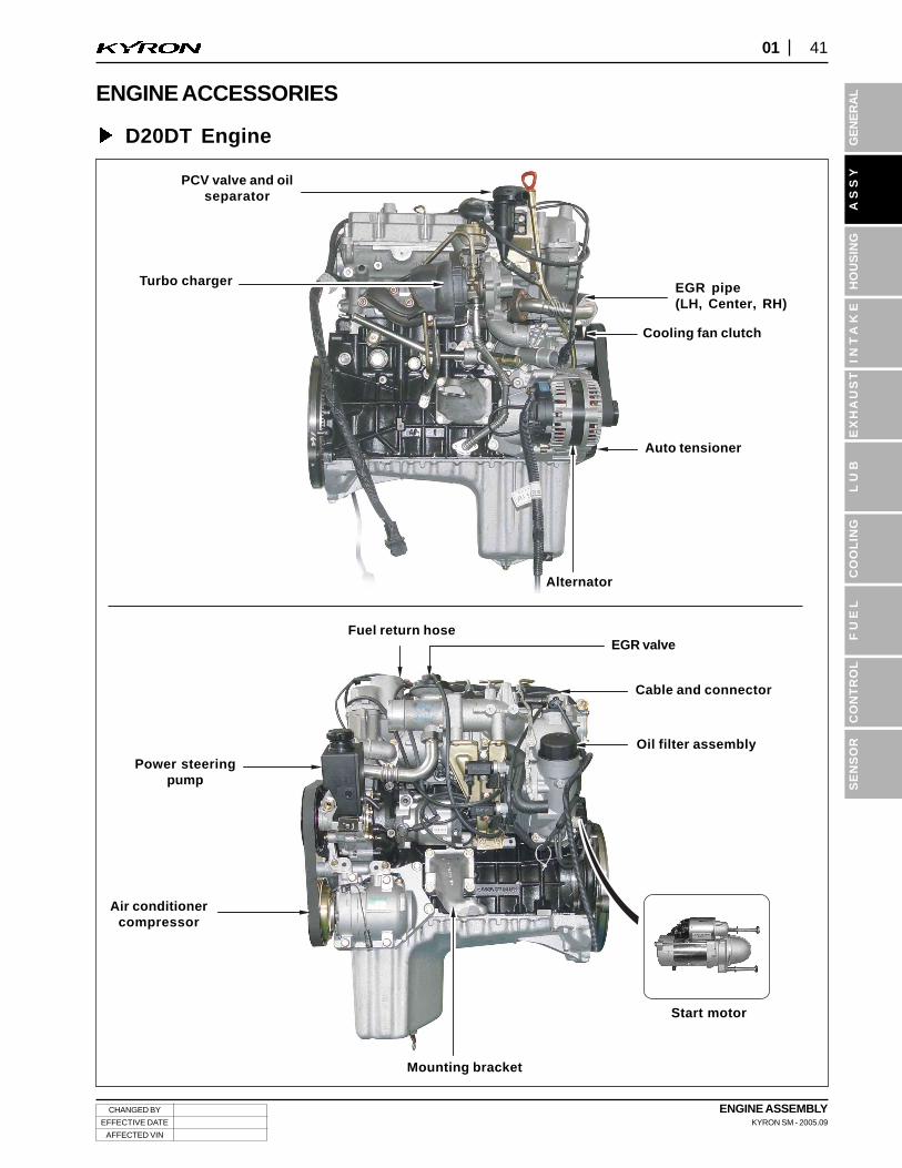
CHANGED BY EFFECTIVE DATE AFFECTED VIN ENGINE ASSEMBLY KYRON SM - 2005.09 41 01 GENERAL SENSOR ASSY HOUSING INTAKE LUB COOLING FUEL CONTROL EXHAUST PCV valve and oil separator EGR pipe (LH, Center, RH) Cooling fan clutch Alternator Turbo charger Fuel return hose Cable and connector Oil filter assembly EGR valve Start motor Mounting bracket Air conditioner compressor ENGINE ACCESSORIES D20DT Engine Auto tensioner Power steering pump
Transcript of ENGINE ACCESSORIES GENERAL212.113.105.12/library/BOOKS/CAR/SsangYong/Kyron/...CHANGED BY EFFECTIVE...
CHANGED BY
EFFECTIVE DATE
AFFECTED VIN
ENGINE ASSEMBLYKYRON SM - 2005.09
4101
GE
NE
RA
LS
EN
SO
RA
SS
YH
OU
SIN
GIN
TA
KE
LU
BC
OO
LIN
GF
UE
LC
ON
TR
OL
EX
HA
US
T
PCV valve and oilseparator
EGR pipe(LH, Center, RH)
Cooling fan clutch
Alternator
Turbo charger
Fuel return hose
Cable and connector
Oil filter assembly
EGR valve
Start motor
Mounting bracket
Air conditionercompressor
ENGINE ACCESSORIES
D20DT Engine
Auto tensioner
Power steeringpump
ENGINE ASSEMBLYKYRON SM - 2005.09
CHANGED BY
EFFECTIVE DATE
AFFECTED VIN
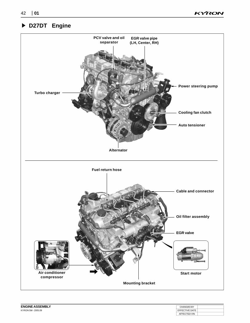
42 01
PCV valve and oilseparator
EGR valve pipe(LH, Center, RH)
Power steering pump
Cooling fan clutch
Auto tensioner
Alternator
Turbo charger
Fuel return hose
Cable and connector
Oil filter assembly
EGR valve
Start motor
Mounting bracket
Air conditionercompressor
D27DT Engine
CHANGED BY
EFFECTIVE DATE
AFFECTED VIN
ENGINE ASSEMBLYKYRON SM - 2005.09
4301
GE
NE
RA
LS
EN
SO
RA
SS
YH
OU
SIN
GIN
TA
KE
LU
BC
OO
LIN
GF
UE
LC
ON
TR
OL
EX
HA
US
T
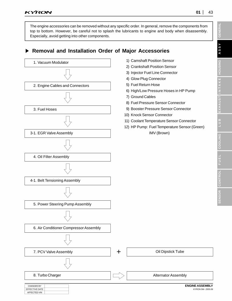
The engine accessories can be removed without any specific order. In general, remove the components fromtop to bottom. However, be careful not to splash the lubricants to engine and body when disassembly.Especially, avoid getting into other components.
Removal and Installation Order of Major Accessories
Oil Dipstick Tube
Alternator Assembly
+
1) Camshaft Position Sensor
2) Crankshaft Position Sensor
3) Injector Fuel Line Connector
4) Glow Plug Connector
5) Fuel Return Hose
6) High/Low Pressure Hoses in HP Pump
7) Ground Cables
8) Fuel Pressure Sensor Connector
9) Booster Pressure Sensor Connector
10) Knock Sensor Connector
11) Coolant Temperature Sensor Connector
12) HP Pump: Fuel Temperature Sensor (Green)
IMV (Brown)
1. Vacuum Modulator
2. Engine Cables and Connectors
3. Fuel Hoses
3-1. EGR Valve Assembly
4. Oil Filter Assembly
4-1. Belt Tensioning Assembly
5. Power Steering Pump Assembly
6. Air Conditioner Compressor Assembly
8. Turbo Charger
7. PCV Valve Assembly

ENGINE ASSEMBLYKYRON SM - 2005.09
CHANGED BY
EFFECTIVE DATE
AFFECTED VIN
44 01
1. Remove the fuel pipes.
1) Remove the fuel supply pipes between each cylinder and common rail with a special tool.
Installation Notice
Tightening torque 40 ± 4.0 Nm
• Plug the openings of injector nozzle and common rail with sealing caps after removed the fuel pipes.
NOTICE
D27DTD20DT
D27DTD20DT
CHANGED BY
EFFECTIVE DATE
AFFECTED VIN
ENGINE ASSEMBLYKYRON SM - 2005.09
4501
GE
NE
RA
LS
EN
SO
RA
SS
YH
OU
SIN
GIN
TA
KE
LU
BC
OO
LIN
GF
UE
LC
ON
TR
OL
EX
HA
US
T
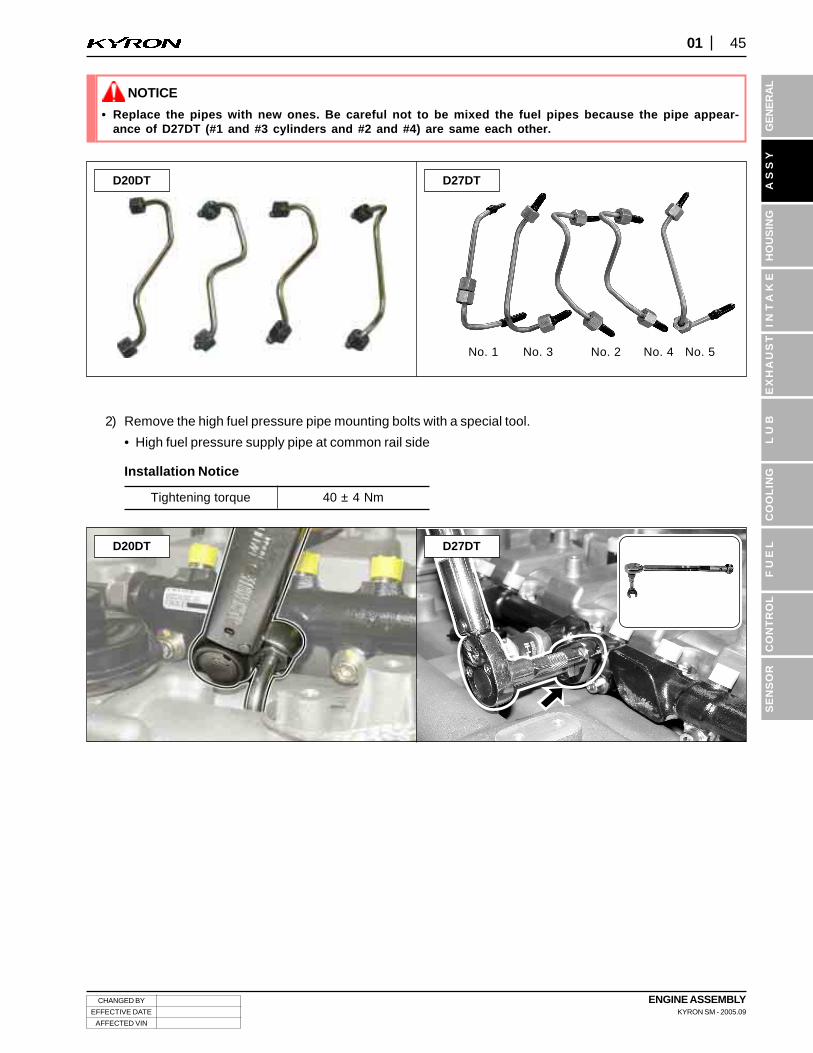
No. 1 No. 3 No. 2 No. 4 No. 5
• Replace the pipes with new ones. Be careful not to be mixed the fuel pipes because the pipe appear-ance of D27DT (#1 and #3 cylinders and #2 and #4) are same each other.
NOTICE
2) Remove the high fuel pressure pipe mounting bolts with a special tool.
• High fuel pressure supply pipe at common rail side
Installation Notice
Tightening torque 40 ± 4 Nm
D27DTD20DT
D27DTD20DT
ENGINE ASSEMBLYKYRON SM - 2005.09
CHANGED BY
EFFECTIVE DATE
AFFECTED VIN
46 01
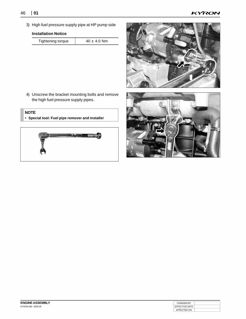
3) High fuel pressure supply pipe at HP pump side
Installation Notice
4) Unscrew the bracket mounting bolts and removethe high fuel pressure supply pipes.
Tightening torque 40 ± 4.0 Nm
• Special tool: Fuel pipe remover and installerNOTE

CHANGED BY
EFFECTIVE DATE
AFFECTED VIN
ENGINE ASSEMBLYKYRON SM - 2005.09
4701
GE
NE
RA
LS
EN
SO
RA
SS
YH
OU
SIN
GIN
TA
KE
LU
BC
OO
LIN
GF
UE
LC
ON
TR
OL
EX
HA
US
T
2. Disconnect the vacuum hoses and module cables from the vacuum modulator.
1) Remove the vacuum modulator bracket.(Upper: 10 M x 2, Lower: 10M x 2)
Installation Notice
Upper bolt
Lower bolt
25 ± 2.5 Nm
25 ± 2.5 Nm
• Put the installation marks on the modulator hoses and connectors.
NOTICE
D27DTD20DT
To EGR valve
To turbo chargerbooster
EGR boostervacuum modulator
Fromvacuumpump
Turbo chargerbooster vacuum
modulator
D27DTD20DT
To turbochargerbooster
Turbo chargerbooster vacuum
modulator
Fromvacuumpump
EGR booster vacuummodulator
ENGINE ASSEMBLYKYRON SM - 2005.09
CHANGED BY
EFFECTIVE DATE
AFFECTED VIN
48 01
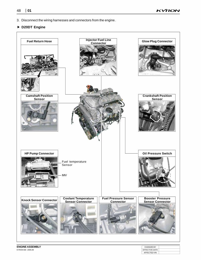
3. Disconnect the wiring harnesses and connectors from the engine.
D20DT Engine
Fuel Return Hose Injector Fuel LineConnector
Glow Plug Connector
Camshaft PositionSensor
Crankshaft PositionSensor
Oil Pressure SwitchHP Pump Connector
Knock Sensor ConnectorCoolant Temperature
Sensor ConnectorFuel Pressure Sensor
ConnectorBooster PressureSensor Connector
Fuel temperatureSensor
IMV
CHANGED BY
EFFECTIVE DATE
AFFECTED VIN
ENGINE ASSEMBLYKYRON SM - 2005.09
4901
GE
NE
RA
LS
EN
SO
RA
SS
YH
OU
SIN
GIN
TA
KE
LU
BC
OO
LIN
GF
UE
LC
ON
TR
OL
EX
HA
US
T
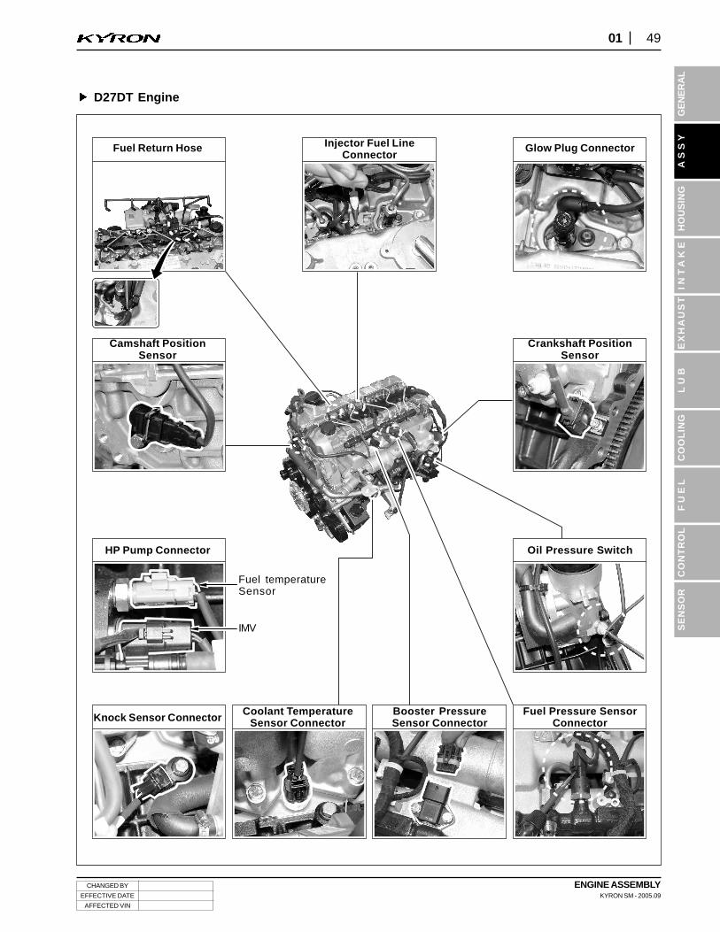
D27DT Engine
Fuel Return Hose Injector Fuel LineConnector
Glow Plug Connector
Camshaft PositionSensor
Crankshaft PositionSensor
Oil Pressure SwitchHP Pump Connector
Knock Sensor ConnectorCoolant Temperature
Sensor ConnectorBooster PressureSensor Connector
Fuel Pressure SensorConnector
Fuel temperatureSensor
IMV
ENGINE ASSEMBLYKYRON SM - 2005.09
CHANGED BY
EFFECTIVE DATE
AFFECTED VIN
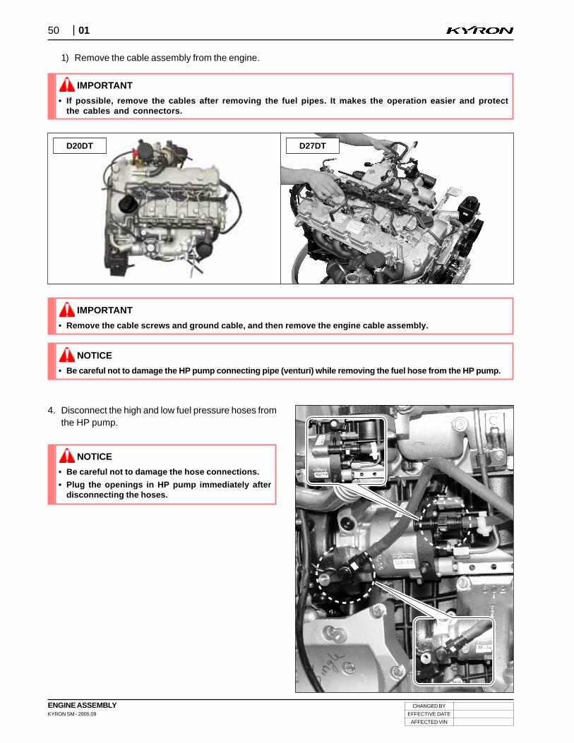
50 01
• Be careful not to damage the HP pump connecting pipe (venturi) while removing the fuel hose from the HP pump.
NOTICE
1) Remove the cable assembly from the engine.
4. Disconnect the high and low fuel pressure hoses fromthe HP pump.
• If possible, remove the cables after removing the fuel pipes. It makes the operation easier and protectthe cables and connectors.
IMPORTANT
D27DTD20DT
• Be careful not to damage the hose connections.
• Plug the openings in HP pump immediately afterdisconnecting the hoses.
NOTICE
• Remove the cable screws and ground cable, and then remove the engine cable assembly.
IMPORTANT
CHANGED BY
EFFECTIVE DATE
AFFECTED VIN
ENGINE ASSEMBLYKYRON SM - 2005.09
5101
GE
NE
RA
LS
EN
SO
RA
SS
YH
OU
SIN
GIN
TA
KE
LU
BC
OO
LIN
GF
UE
LC
ON
TR
OL
EX
HA
US
T
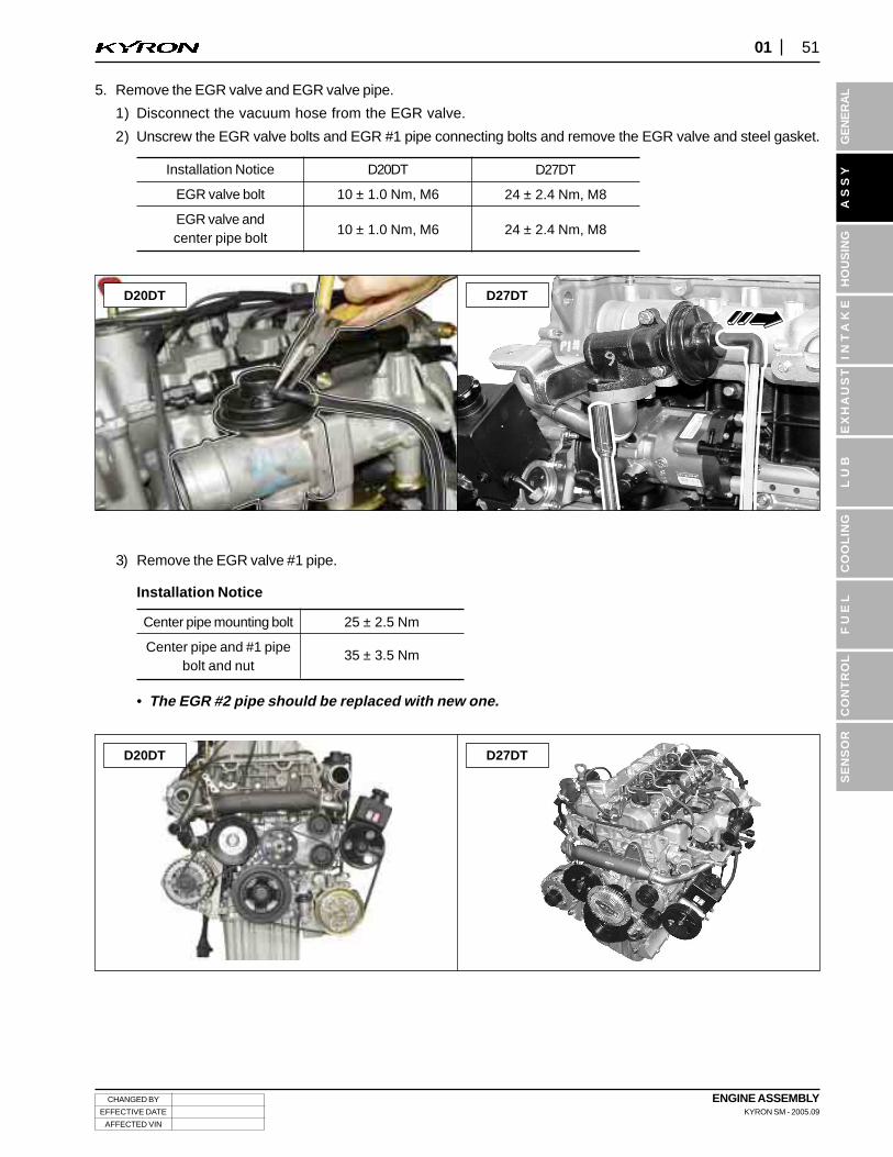
3) Remove the EGR valve #1 pipe.
Installation Notice
• The EGR #2 pipe should be replaced with new one.
Center pipe mounting bolt
Center pipe and #1 pipebolt and nut
25 ± 2.5 Nm
35 ± 3.5 Nm
D27DTD20DT
5. Remove the EGR valve and EGR valve pipe.
1) Disconnect the vacuum hose from the EGR valve.
2) Unscrew the EGR valve bolts and EGR #1 pipe connecting bolts and remove the EGR valve and steel gasket.
Installation Notice
EGR valve bolt
EGR valve andcenter pipe bolt
D20DT
10 ± 1.0 Nm, M6
10 ± 1.0 Nm, M6
D27DTD20DT
D27DT
24 ± 2.4 Nm, M8
24 ± 2.4 Nm, M8
ENGINE ASSEMBLYKYRON SM - 2005.09
CHANGED BY
EFFECTIVE DATE
AFFECTED VIN
52 01
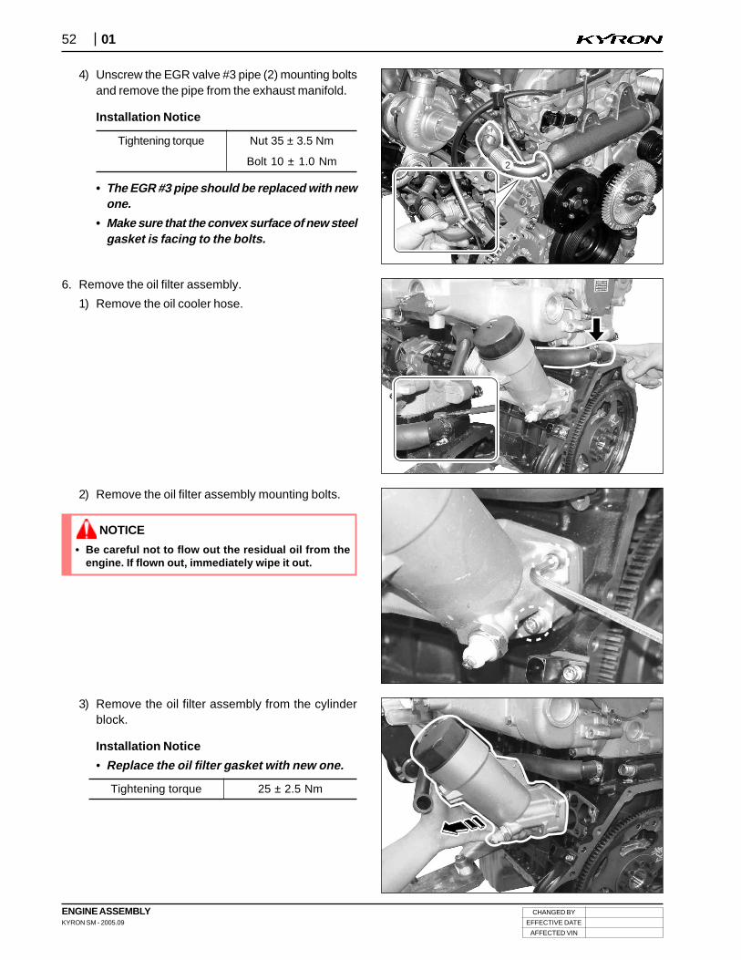
4) Unscrew the EGR valve #3 pipe (2) mounting boltsand remove the pipe from the exhaust manifold.
Installation Notice
Tightening torque Nut 35 ± 3.5 Nm
Bolt 10 ± 1.0 Nm
• The EGR #3 pipe should be replaced with newone.
• Make sure that the convex surface of new steelgasket is facing to the bolts.
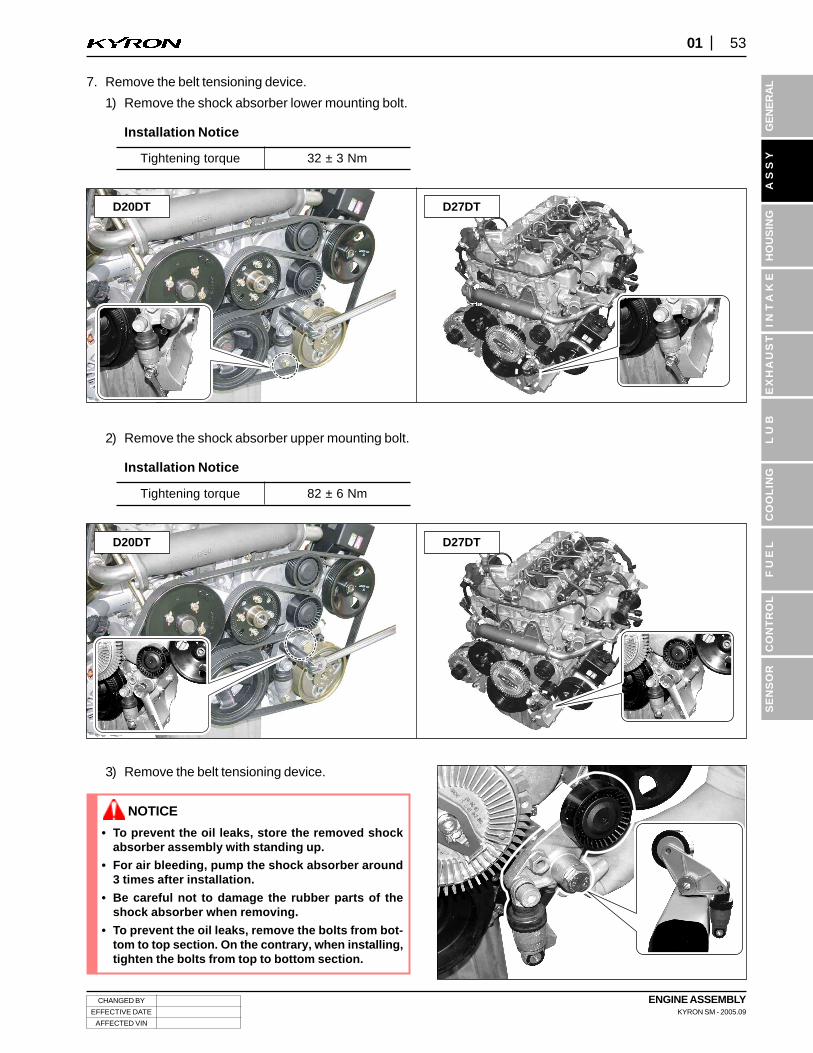
6. Remove the oil filter assembly.
1) Remove the oil cooler hose.
2
2) Remove the oil filter assembly mounting bolts.
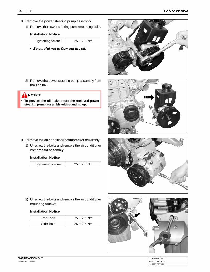
3) Remove the oil filter assembly from the cylinderblock.
Installation Notice
• Replace the oil filter gasket with new one.
Tightening torque 25 ± 2.5 Nm
• Be careful not to flow out the residual oil from theengine. If flown out, immediately wipe it out.
NOTICE
CHANGED BY
EFFECTIVE DATE
AFFECTED VIN
ENGINE ASSEMBLYKYRON SM - 2005.09
5301
GE
NE
RA
LS
EN
SO
RA
SS
YH
OU
SIN
GIN
TA
KE
LU
BC
OO
LIN
GF
UE
LC
ON
TR
OL
EX
HA
US
T3) Remove the belt tensioning device.
• To prevent the oil leaks, store the removed shockabsorber assembly with standing up.
• For air bleeding, pump the shock absorber around3 times after installation.
• Be careful not to damage the rubber parts of theshock absorber when removing.
• To prevent the oil leaks, remove the bolts from bot-tom to top section. On the contrary, when installing,tighten the bolts from top to bottom section.
NOTICE
7. Remove the belt tensioning device.
1) Remove the shock absorber lower mounting bolt.
Installation Notice
2) Remove the shock absorber upper mounting bolt.
Installation Notice
Tightening torque 32 ± 3 Nm
Tightening torque 82 ± 6 Nm
D27DTD20DT
D27DTD20DT
ENGINE ASSEMBLYKYRON SM - 2005.09
CHANGED BY
EFFECTIVE DATE
AFFECTED VIN
54 01
2) Remove the power steering pump assembly fromthe engine.
9. Remove the air conditioner compressor assembly.
1) Unscrew the bolts and remove the air conditionercompressor assembly.
Installation Notice
8. Remove the power steering pump assembly.
1) Remove the power steering pump mounting bolts.
Installation Notice
Tightening torque 25 ± 2.5 Nm
• Be careful not to flow out the oil.
Tightening torque 25 ± 2.5 Nm
• To prevent the oil leaks, store the removed powersteering pump assembly with standing up.
NOTICE
2) Unscrew the bolts and remove the air conditionermounting bracket.
Installation Notice
Front bolt
Side bolt
25 ± 2.5 Nm
25 ± 2.5 Nm
CHANGED BY
EFFECTIVE DATE
AFFECTED VIN
ENGINE ASSEMBLYKYRON SM - 2005.09
5501
GE
NE
RA
LS
EN
SO
RA
SS
YH
OU
SIN
GIN
TA
KE
LU
BC
OO
LIN
GF
UE
LC
ON
TR
OL
EX
HA
US
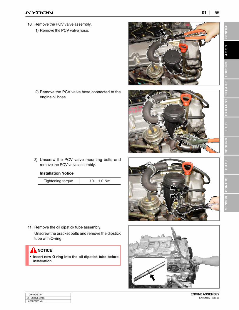
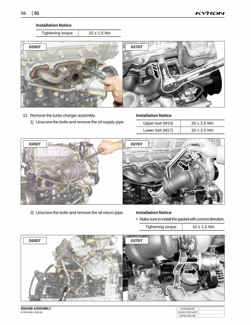
T11. Remove the oil dipstick tube assembly.
Unscrew the bracket bolts and remove the dipsticktube with O-ring.
• Insert new O-ring into the oil dipstick tube beforeinstallation.
NOTICE
10. Remove the PCV valve assembly.
1) Remove the PCV valve hose.
2) Remove the PCV valve hose connected to theengine oil hose.
3) Unscrew the PCV valve mounting bolts andremove the PCV valve assembly.
Installation Notice
Tightening torque 10 ± 1.0 Nm
ENGINE ASSEMBLYKYRON SM - 2005.09
CHANGED BY
EFFECTIVE DATE
AFFECTED VIN
56 01
2) Unscrew the bolts and remove the oil return pipe.
D27DTD20DT
Installation Notice
Tightening torque 10 ± 1.0 Nm
D27DTD20DT
12. Remove the turbo charger assembly.
1) Unscrew the bolts and remove the oil supply pipe. Upper bolt (M19)
Lower bolt (M17)
25 ± 2.5 Nm
20 ± 2.0 Nm
Tightening torque 10 ± 1.0 Nm
D27DTD20DT
Installation Notice
• Make sure to install the gasket with correct direction.
Installation Notice
CHANGED BY
EFFECTIVE DATE
AFFECTED VIN
ENGINE ASSEMBLYKYRON SM - 2005.09
5701
GE
NE
RA
LS
EN
SO
RA
SS
YH
OU
SIN
GIN
TA
KE
LU
BC
OO
LIN
GF
UE
LC
ON
TR
OL
EX
HA
US
T
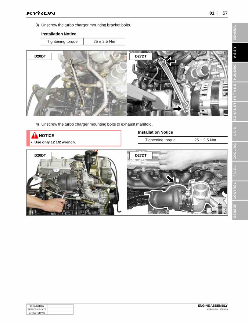
3) Unscrew the turbo charger mounting bracket bolts.
Installation Notice
4) Unscrew the turbo charger mounting bolts to exhaust manifold.
Installation Notice
Tightening torque 25 ± 2.5 Nm
Tightening torque 25 ± 2.5 Nm• Use only 12 1/2 wrench.
NOTICE
D27DTD20DT
D27DTD20DT
ENGINE ASSEMBLYKYRON SM - 2005.09
CHANGED BY
EFFECTIVE DATE
AFFECTED VIN
58 01
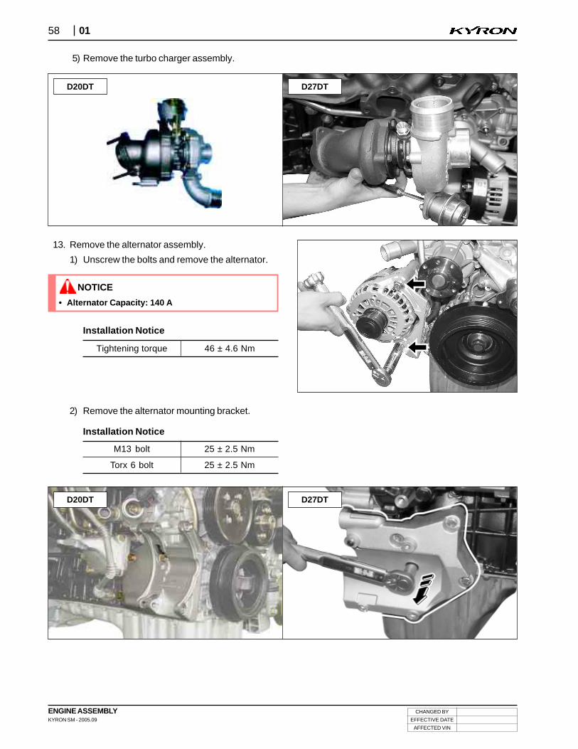
5) Remove the turbo charger assembly.
13. Remove the alternator assembly.
1) Unscrew the bolts and remove the alternator.
Tightening torque 46 ± 4.6 Nm
• Alternator Capacity: 140 A
NOTICE
Installation Notice
2) Remove the alternator mounting bracket.
Installation Notice
M13 bolt
Torx 6 bolt
25 ± 2.5 Nm
25 ± 2.5 Nm
D27DTD20DT
D27DTD20DT