ENGG4420 ‐‐ CHAPTER 2 ‐‐ REAL TIME EMBEDDED … · Interrupt Latency, Response and Recovery...
139
CONTENT OF THE CHAPTER SURVEY OF CONTEMPORARY REAL‐TIME OPERATING SYSTEMS, BENCHMARKS • The Kernel ○ The Scheduler; Objects; Services RTOS Components ○ REAL TIME OPERATING SYSTEMS (RTOS) • System Initialization and Starting and Program organization ○ Tasks, Tasks States, and Task Operations ○ Interrupt Latency, Response and Recovery Clock Tick Interrupts ○ Event Control Blocks Objects: semaphores, mutexes, mailboxes, message queues. Synchronization, Communication and Concurrency ○ uC/OS‐II • PIP, PCP PROTOCOLS • REFERENCES: [1] J. J. Lambrosse, MicroC/OS‐II Second Edition [2] T. D. Morton, Embedded Controllers [3] R. Mall, Real‐Time Systems ENGG4420 ‐‐ CHAPTER 2 ‐‐ REAL TIME EMBEDDED SYSTEMS DESIGN ‐‐ LECTURE 1 October‐30‐09 4:10 PM CHAPTER 2 By Radu Muresan University of Guelph Page 1
Transcript of ENGG4420 ‐‐ CHAPTER 2 ‐‐ REAL TIME EMBEDDED … · Interrupt Latency, Response and Recovery...
CONTENT OF THE CHAPTERSURVEY OF CONTEMPORARY REAL‐TIME OPERATING SYSTEMS, BENCHMARKS
•
The Kernel○
The Scheduler; Objects; ServicesRTOS Components○
REAL TIME OPERATING SYSTEMS (RTOS)•
System Initialization and Starting and Program organization
○
Tasks, Tasks States, and Task Operations○
Interrupt Latency, Response and RecoveryClock Tick
Interrupts○
Event Control BlocksObjects: semaphores, mutexes, mailboxes, message queues.
Synchronization, Communication and Concurrency○
uC/OS‐II•
PIP, PCP PROTOCOLS•REFERENCES: [1] J. J. Lambrosse, MicroC/OS‐II Second Edition[2] T. D. Morton, Embedded Controllers[3] R. Mall, Real‐Time Systems
ENGG4420 ‐‐ CHAPTER 2 ‐‐ REAL TIME EMBEDDED SYSTEMS DESIGN ‐‐ LECTURE 1October‐30‐094:10 PM
CHAPTER 2 By Radu Muresan University of Guelph Page 1

Helps us to decide which RTOS is suitable for a specific real‐time application
○
Many of these OS come with a set of tools to facilitate the development of real‐time applications
○
Tools such as memory utilization, performance profilers, simulators, etc.
Besides the general programming tools such as editors, compilers, and debuggers, specialized tools designed for the development of real‐time applications are present.
○
We briefly survey the important features of some of the popular real‐time operating systems that are being used in commercial applications.
•
PSOS○VRTX○VxWorks○QNX○uC/OS‐II○RT Linux○Lynx○Windows CE○
The RTOS discussed are:•
A SURVEY OF CONTEMPORARY REAL‐TIME OPERATING SYSTEMSNovember‐06‐0912:46 PM
CHAPTER 2 By Radu Muresan University of Guelph Page 2
REAL‐TIME POSIX STANDARD
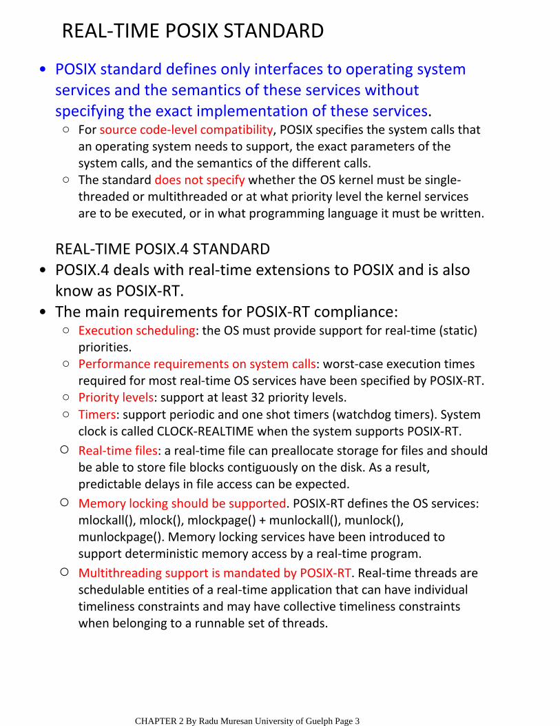
For source code‐level compatibility, POSIX specifies the system calls that an operating system needs to support, the exact parameters of the system calls, and the semantics of the different calls.
○
The standard does not specify whether the OS kernel must be single‐threaded or multithreaded or at what priority level the kernel services are to be executed, or in what programming language it must be written.
○
POSIX standard defines only interfaces to operating system services and the semantics of these services without specifying the exact implementation of these services.
•
REAL‐TIME POSIX.4 STANDARDPOSIX.4 deals with real‐time extensions to POSIX and is also know as POSIX‐RT.
•
Execution scheduling: the OS must provide support for real‐time (static) priorities.
○
Performance requirements on system calls: worst‐case execution times required for most real‐time OS services have been specified by POSIX‐RT.
○
Priority levels: support at least 32 priority levels.○Timers: support periodic and one shot timers (watchdog timers). System clock is called CLOCK‐REALTIME when the system supports POSIX‐RT.
○
Real‐time files: a real‐time file can preallocate storage for files and should be able to store file blocks contiguously on the disk. As a result, predictable delays in file access can be expected.
○
Memory locking should be supported. POSIX‐RT defines the OS services: mlockall(), mlock(), mlockpage() + munlockall(), munlock(), munlockpage(). Memory locking services have been introduced to support deterministic memory access by a real‐time program.
○
Multithreading support is mandated by POSIX‐RT. Real‐time threads are schedulable entities of a real‐time application that can have individual timeliness constraints and may have collective timeliness constraints when belonging to a runnable set of threads.
○
The main requirements for POSIX‐RT compliance:•
CHAPTER 2 By Radu Muresan University of Guelph Page 3
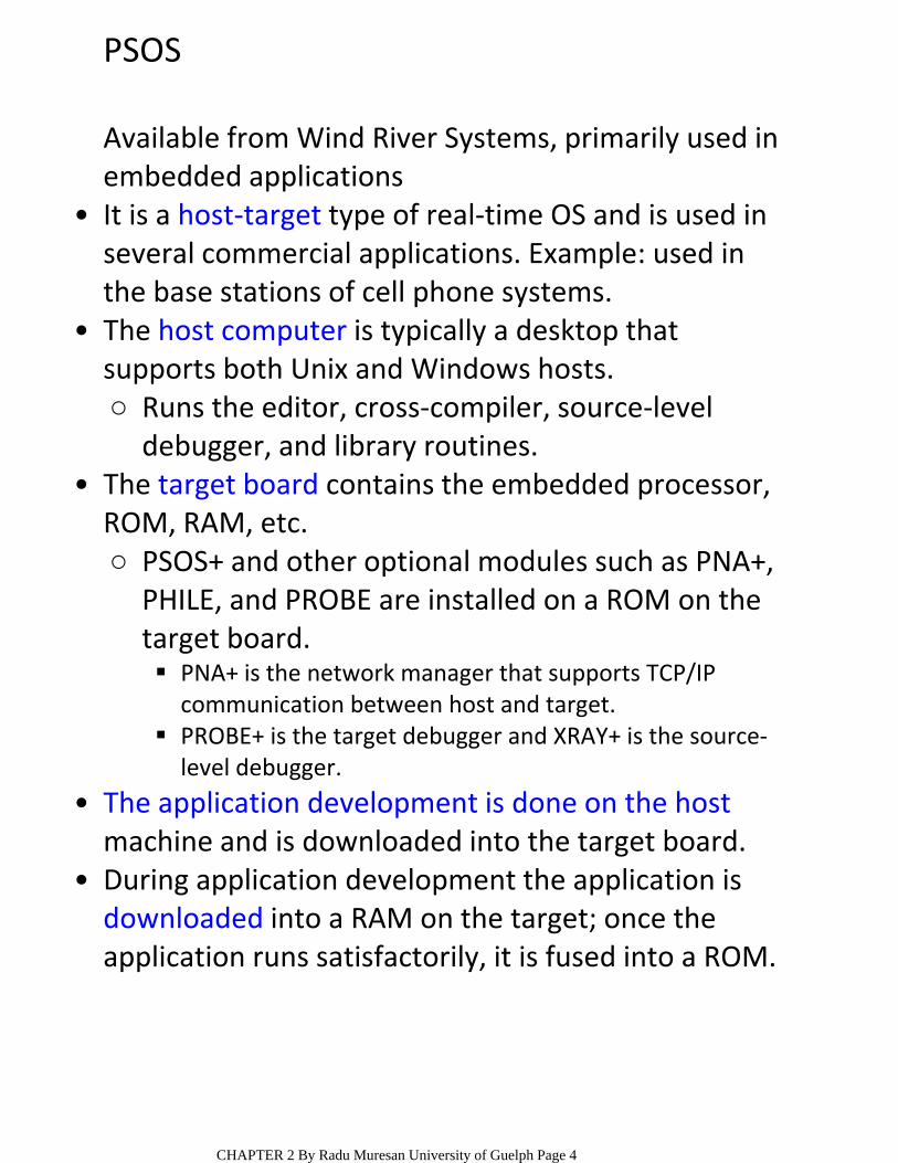
PSOS
Available from Wind River Systems, primarily used in embedded applicationsIt is a host‐target type of real‐time OS and is used in several commercial applications. Example: used in the base stations of cell phone systems.
•
Runs the editor, cross‐compiler, source‐level debugger, and library routines.
○
The host computer is typically a desktop that supports both Unix and Windows hosts.
•
PNA+ is the network manager that supports TCP/IP communication between host and target.
PROBE+ is the target debugger and XRAY+ is the source‐level debugger.
PSOS+ and other optional modules such as PNA+, PHILE, and PROBE are installed on a ROM on the target board.
○
The target board contains the embedded processor, ROM, RAM, etc.
•
The application development is done on the hostmachine and is downloaded into the target board.
•
During application development the application is downloaded into a RAM on the target; once the application runs satisfactorily, it is fused into a ROM.
•
CHAPTER 2 By Radu Muresan University of Guelph Page 4
FEATURES OF PSOS
PSOS supports 32 levels of priority.•In the minimal configuration the foot print of the target OS is only 12 KB.
•
For sharing critical resources among real‐time tasks, it supports PIP and PCP.
•
PSOS defines a memory region to be physically continuous block of memory;
○
a memory region is created by the OS in response to a call from an application;
○
a programmer can allocate a task to a memory region.
○
It supports segmented memory management but does not support virtual memory.
•
In most modern OS the control jumps to the kernel when an interrupt occurs. For PSOS, the device drivers are outside the kernel and can be loaded and removed at the run time. As a result, when an interrupt occurs, the processor jumps directly to the ISR pointed by the vector table. As a result, gained speed + application developer has complete control over the interrupt handling.
•
CHAPTER 2 By Radu Muresan University of Guelph Page 5
VRTX
VRTX is a POSIX‐RT compliant OS from Mentor Graphics.
•
VRTX has been certified by US FAA (Federal Aviation Agency) for use in mission and life‐critical applications such as avionics.
•
Supports virtual memory; has a POSIX‐compliant library; supports priority inheritance protocol; its system calls complete deterministically (in fixed time intervals) and are fully preemptable
VRTXsa is used for large and medium‐size applications
○
It targets embedded applications such as computer‐based toys, cell phones, and other handheld devices
The kernel typically requires only 4 to 8 KB of ROM and 1 KB of RAM;
It does not support virtual memory;
VRTXmc is optimized for power consumption and ROM and RAM sizes and it has a very small footprint.
○
VRTX is available in two versions:•
CHAPTER 2 By Radu Muresan University of Guelph Page 6
VxWORKS
VxWorks is a product from Wind River Systems. It is a host‐target type RTOS and the host can be either Windows or Unix machines.
•
VxWorks confirms to POSIX‐RT and comes with an Integrated Development Environment (IDE) called Tornado.
•
VxSim simulates a VxWorks target for use as a prototyping and testing environment in the absence of the actual target board
○
WindView provides debugging tools for the simulator environment
○
VxMP is the multiprocessor version of VxWorks○
Tornado comes with standard support for program development tools such as editor, cross‐compiler, cross‐debugger, etc. plus it contains VxSim and WindView
•
The system proved to have a bug due to unbounded priority inversion that caused real‐time tasks to miss their deadlines
○
The problem was fixed by remote debugging○
VxWorks was deployed in the Mars Pathfinder which was sent to Mars in 1997
•
CHAPTER 2 By Radu Muresan University of Guelph Page 7
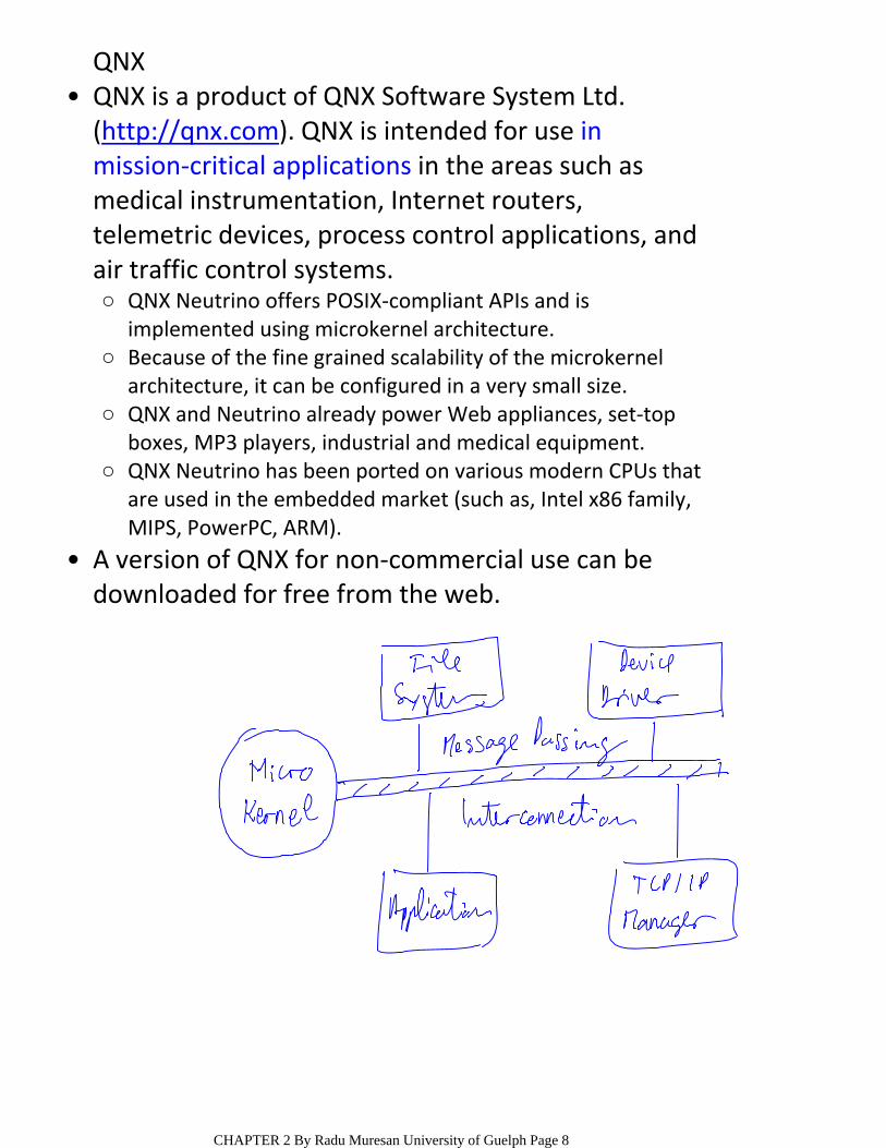
QNX
QNX Neutrino offers POSIX‐compliant APIs and is implemented using microkernel architecture.
○
Because of the fine grained scalability of the microkernel architecture, it can be configured in a very small size.
○
QNX and Neutrino already power Web appliances, set‐top boxes, MP3 players, industrial and medical equipment.
○
QNX Neutrino has been ported on various modern CPUs that are used in the embedded market (such as, Intel x86 family, MIPS, PowerPC, ARM).
○
QNX is a product of QNX Software System Ltd. (http://qnx.com). QNX is intended for use in mission‐critical applications in the areas such as medical instrumentation, Internet routers, telemetric devices, process control applications, and air traffic control systems.
•
A version of QNX for non‐commercial use can be downloaded for free from the web.
•
CHAPTER 2 By Radu Muresan University of Guelph Page 8
uC/OS‐II
uC/OS‐II is available from Micrium Corporation. This RTOS is written in ANSI C and contains a small portion of assembly code. The assembly language portion has been kept to minimum to allow for easy portability.uC/OS‐II has been ported to over 100 different processor architectures ranging from 8‐bit to 64‐bit microprocessors, microcontrollers, and DSPs.
•
Programmers have the option of using just a few of the offered services or select the entire range
○
Has a fully preemptive kernel○Allows up to 64 tasks to be created○Uses a partitioned memory management scheme. Each memory partition consists of several fixed sized blocks. A task obtains memory blocks from the memory partition and the task must create a memory partition before it can be used. Allocation and deallocation of fixed‐sized memory blocks is done in constant time and is deterministic.
○
Has been certified by the Federal Aviation Administration (FAA) for use in commercial aircraft and meets the demanding requirements of its standard to be used in avionics.
○
Some of the important features of uC/OS‐II are:•
CHAPTER 2 By Radu Muresan University of Guelph Page 9

RT LINUX
Linux is a free general purpose OS. Several real‐time implementations of Linux (RTLinux) are available.RTLinux is a self‐host operating system that runs along with Linux system.
•
The RT Linux kernel intercepts all interrupts generated by hardware; interrupts not related to real‐time activity are passed to the Linux kernel as software interrupts.
○
If an interrupt is to cause a real‐time task to run, the real‐time kernel preempts Linux; thus Linux runs as a low priority background task of RT Linux.
○
Real‐time applications are written as loadable kernel modules and run in the kernel space.
○
The real‐time kernel sits between the hardware and the Linux system; to the standard Linux kernel, the RT Linux layer appears to be the actual hardware.
•
Duplicate coding efforts ‐ new drivers and system services must be created specifically for the real‐time kernel;
○
Fragile execution environment ‐ real‐time tasks that contain a coding error such as a corrupt C pointer can easily cause a fatal kernel fault.
○
Limited portability ‐ real‐time programs written using one vendor's RT‐Linux version may not run on another.
○
Programming difficulty ‐ supports only a limited subset of POSIX APIs.
○
This approach is known as the dual kernel approach. The following are some of the important short‐comings of the dual‐kernel approach:
•
CHAPTER 2 By Radu Muresan University of Guelph Page 10
LYNX
Linx is a self‐host real‐time OS and is available from www.lynuxworks.com; Lynx 3.0 is a microkernel‐based real‐time OSLynx is fully compatible with Linux. A Linux program's binary image can be run directly on Lynx ‐ on the other hand for other Linux compatible OS such as QNX, Linux applications need to be recompiled in order to run on them.
•
Lynx is 28 KB in size and provides essential services for task scheduling, interrupt dispatch, and synchronization
•
By adding KPIs to the microkernel the system can be configured to support I/O, file systems, sockets, and so on.
○Other services are provided as Kernel Plug‐Ins (KPIs)•
With full configuration, it can even function as a multipurpose Unix machine on which both hard and soft real‐time tasks can run.
•
Unlike many embedded RTOSs Lynx supports memory protection
•
CHAPTER 2 By Radu Muresan University of Guelph Page 11
WINDOWS CE
Windows CE is a stripped down version of Windows OS, and has a minimum footprint of 400 KB.It provides 256 priority levels and to optimize performance all threads are run in the kernel mode.
•
The timer accuracy is 1 ms for sleep and wait related APIs.
•
The different functionalities of the kernel are broken down into small non‐preemptive sections. As a result during system call, preemption is turned off for only short periods of time.
•
Interrupt servicing is preemptible supporting nested interrupts.
•
Uses Memory Management Unit (MMU) for virtual memory management.
•
The Windows CE ensures that a thread is not blocked by any lower priority thread, even when it suffers a page fault.
○
Uses a priority inheritance scheme to avoid the priority inversion problem that is present in Windows NT.
•
CHAPTER 2 By Radu Muresan University of Guelph Page 12
COMPUTER PLATFORM BENCHMARKINGIn order to overcome misleading metrics such as MIPS, FLOPS, peak MIPS, and peak FLOPS synthetic benchmarks have been developed.
•
The benchmark program do not need to compute any meaningful results => synthetic benchmark
○
Wheatstone, Linpack and Dhrystone
Examples of synthetic benchmarks (see www.spec.org) are:
○
Synthetic benchmarks are created based on statistical distribution of various instructions in an average program (e.g., arithmetic instructions 20%, I/O 10%, register transfer 10%, etc.)
•
REAL‐TIME SYSTEMS BENCHMARKSA popular real‐time systems benchmark is Rhealstone metric.
•
1) Task Switching Time; 2) Task Preemption Time; 3) Interrupt Latency Time; 4) Semaphore Shuffling Time; 5) Unbounded Priority Inversion Time; 6) Datagram Throughput Time.
In Rhealstone metric, six parameters of real‐time systems are considered:
•
BENCHMARKING REAL‐TIME SYSTEMSNovember‐07‐093:50 PM
CHAPTER 2 By Radu Muresan University of Guelph Page 13

TASK SWITCHING TIME (tts)
Task switching time is defined as the time it takes for one context switch among equal priority tasks
•
Example: T1, T2, T3 are equal priority tasks and round‐robin option among equal priority is supported by the scheduler
•
tts is the time after which T2 starts to execute after T1 completes its time slice, blocks or completes
○tts = t2 ‐ t1; •
Task switching time is determined by the efficiency of the kernel data structure
•
CHAPTER 2 By Radu Muresan University of Guelph Page 14
TASK PREEMPTION TIME (ttp)
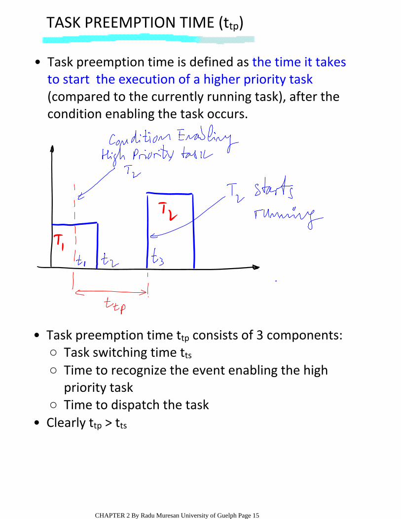
Task preemption time is defined as the time it takes to start the execution of a higher priority task(compared to the currently running task), after the condition enabling the task occurs.
•
Task switching time tts○Time to recognize the event enabling the high priority task
○
Time to dispatch the task○
Task preemption time ttp consists of 3 components:•
Clearly ttp > tts•
CHAPTER 2 By Radu Muresan University of Guelph Page 15
INTERRUPT LATENCY TIME (til)
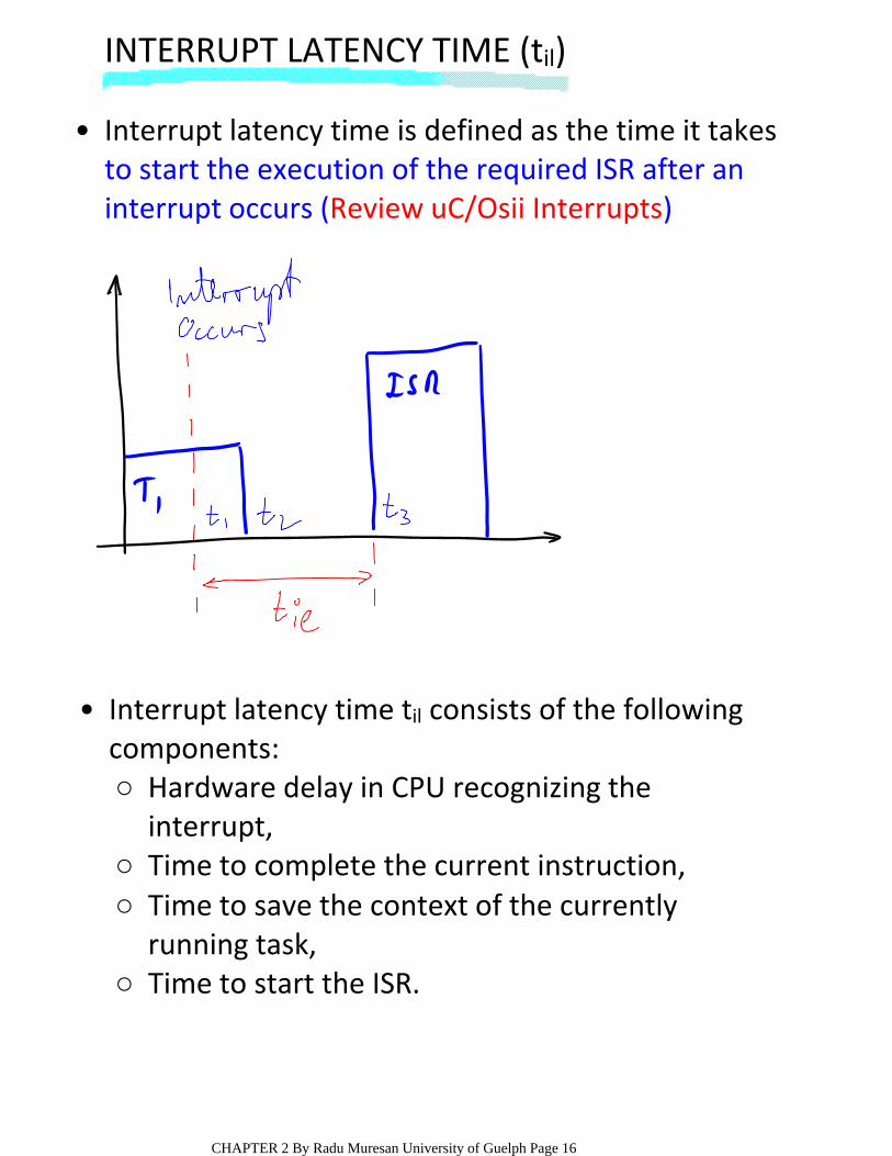
Interrupt latency time is defined as the time it takes to start the execution of the required ISR after an interrupt occurs (Review uC/Osii Interrupts)
•
Hardware delay in CPU recognizing the interrupt,
○
Time to complete the current instruction,○Time to save the context of the currently running task,
○
Time to start the ISR.○
Interrupt latency time til consists of the following components:
•
CHAPTER 2 By Radu Muresan University of Guelph Page 16
SEMAPHORE SHUFFLING TIME (tss)
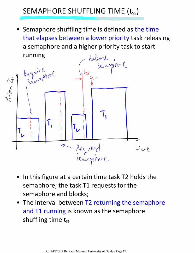
Semaphore shuffling time is defined as the time that elapses between a lower priority task releasing a semaphore and a higher priority task to start running
•
In this figure at a certain time task T2 holds the semaphore; the task T1 requests for the semaphore and blocks;
•
The interval between T2 returning the semaphore and T1 running is known as the semaphore shuffling time tss
•
CHAPTER 2 By Radu Muresan University of Guelph Page 17
UNBOUNDED PRIORITY INVERSION TIME (tup)
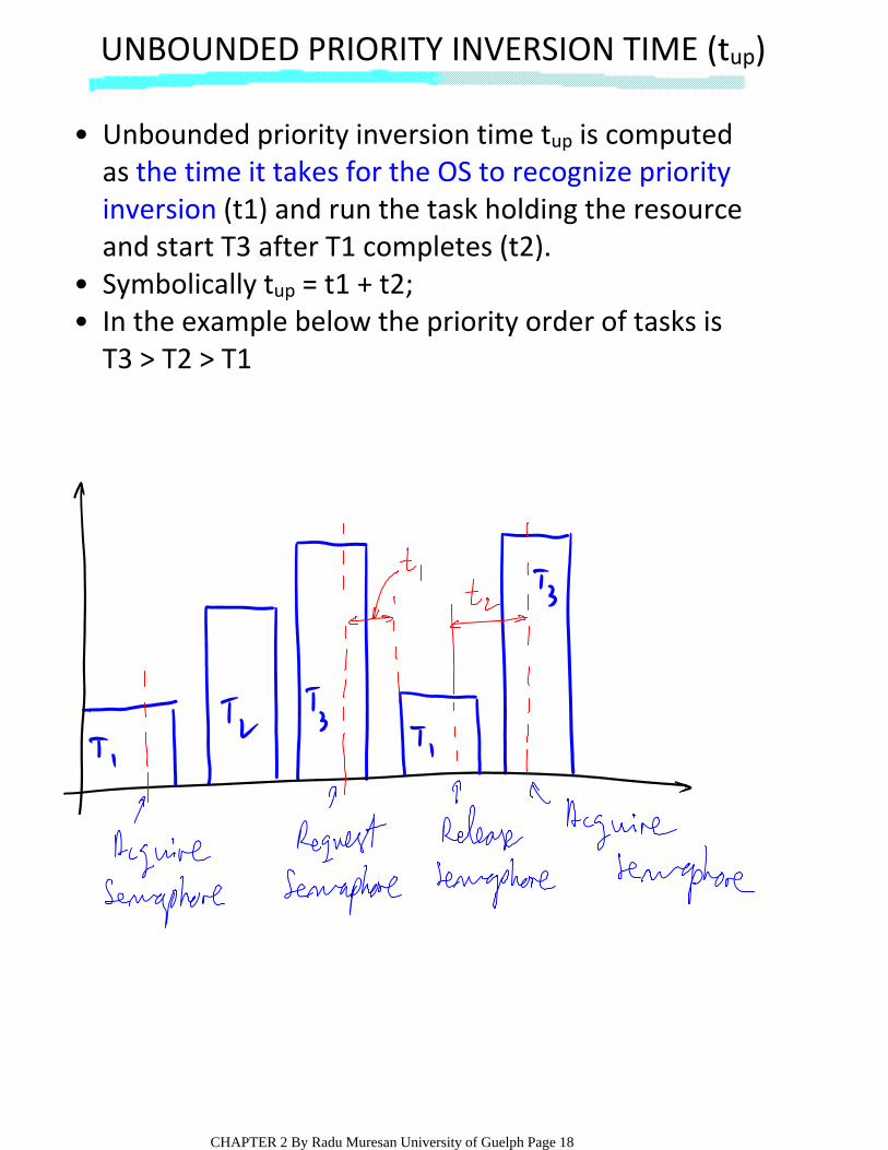
Unbounded priority inversion time tup is computed as the time it takes for the OS to recognize priority inversion (t1) and run the task holding the resource and start T3 after T1 completes (t2).
•
Symbolically tup = t1 + t2;•In the example below the priority order of tasks is T3 > T2 > T1
•
CHAPTER 2 By Radu Muresan University of Guelph Page 18
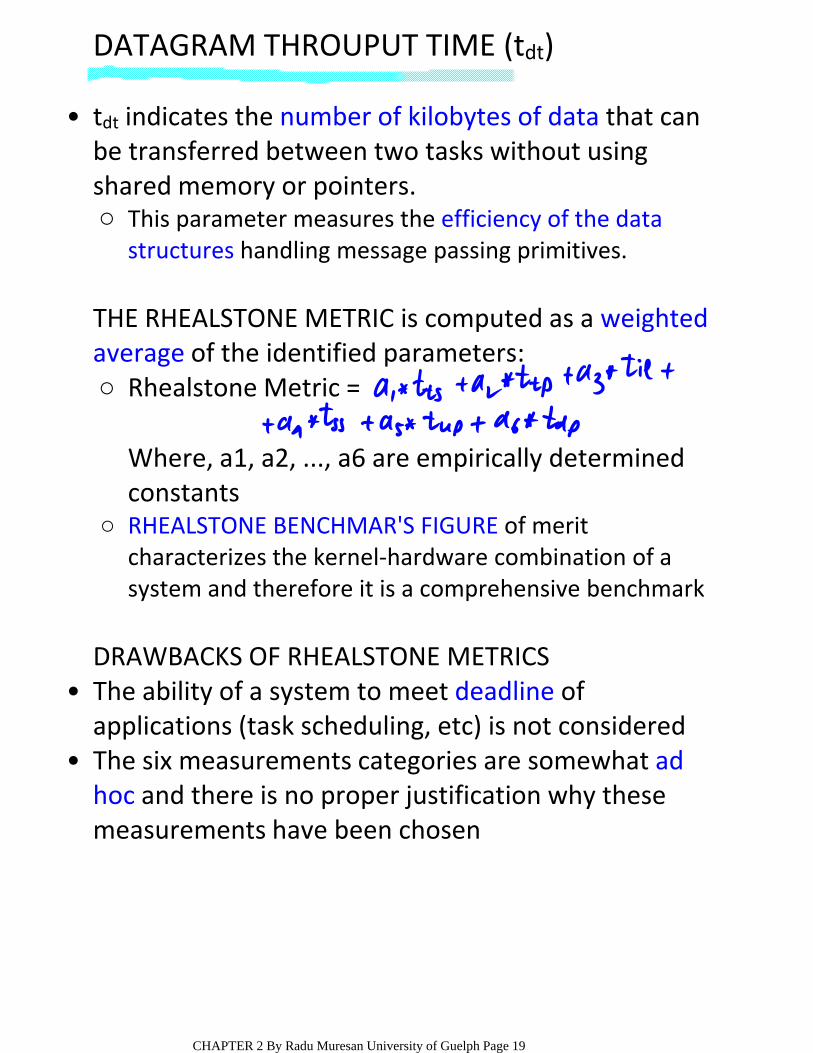
DATAGRAM THROUPUT TIME (tdt)
This parameter measures the efficiency of the data structures handling message passing primitives.
○
tdt indicates the number of kilobytes of data that can be transferred between two tasks without using shared memory or pointers.
•
Rhealstone Metric = ○
Where, a1, a2, ..., a6 are empirically determined constantsRHEALSTONE BENCHMAR'S FIGURE of merit characterizes the kernel‐hardware combination of a system and therefore it is a comprehensive benchmark
○
THE RHEALSTONE METRIC is computed as a weighted average of the identified parameters:
DRAWBACKS OF RHEALSTONE METRICSThe ability of a system to meet deadline of applications (task scheduling, etc) is not considered
•
The six measurements categories are somewhat ad hoc and there is no proper justification why these measurements have been chosen
•
CHAPTER 2 By Radu Muresan University of Guelph Page 19

INTERRUPT PROCESSING OVERHEAD
Let t0 be the time to complete a certain task when there are no interrupts and let t20,000 be the time to complete the same task when 20,000 interrupts occur per second
•
TRIDIMENSIONAL MEASURE (TM)
Millions of Instructions Processed per Second (MIPS1)
○
Millions of Interrupts Processed per Second (MIPS2)
○
Number of I/O Operations Per Second (NIOPS)○
Considers three factors that affect the performance of a real‐time system:
CHAPTER 2 By Radu Muresan University of Guelph Page 20
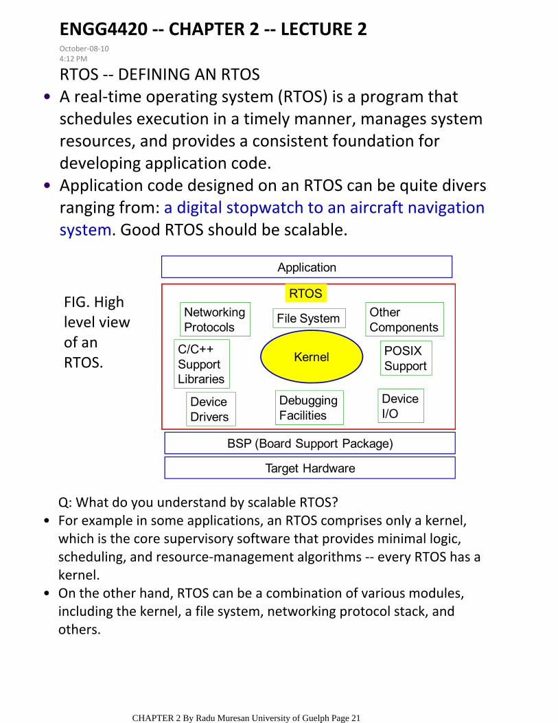
RTOS ‐‐ DEFINING AN RTOSA real‐time operating system (RTOS) is a program that schedules execution in a timely manner, manages system resources, and provides a consistent foundation for developing application code.
•
Application code designed on an RTOS can be quite divers ranging from: a digital stopwatch to an aircraft navigation system. Good RTOS should be scalable.
•
Q: What do you understand by scalable RTOS?For example in some applications, an RTOS comprises only a kernel, which is the core supervisory software that provides minimal logic, scheduling, and resource‐management algorithms ‐‐ every RTOS has a kernel.
•
On the other hand, RTOS can be a combination of various modules, including the kernel, a file system, networking protocol stack, and others.
•
Application
RTOS
NetworkingProtocols
C/C++ SupportLibraries
Device Drivers
File System
Kernel
DebuggingFacilities
Other Components
POSIXSupport
DeviceI/O
BSP (Board Support Package)
Target Hardware
FIG. High level view of an RTOS.
ENGG4420 ‐‐ CHAPTER 2 ‐‐ LECTURE 2October‐08‐104:12 PM
CHAPTER 2 By Radu Muresan University of Guelph Page 21

KERNELSThe kernel is the part of a multitasking system responsible for management of tasks and communication between tasks ‐‐ the fundamental service provided by the kernel is context switching.
•
In a well‐designed application, a kernel uses between 2 and 5% of CPU time.
•
Scheduler – is contained within each kernel and follows a set of algorithms that determines which task executes when.
○
Objects – are special kernel constructs that help developers create applications for real‐time embedded systems
○
Services – are operations that the kernel performs on an object or, generally operations such timing, interrupt, resource management.
○
Most RTOS kernels contain the following components:•
Common scheduling algorithms include round‐robin and preemptive scheduling.
•
Common objects include: tasks, semaphores, and message queues.
•
CHAPTER 2 By Radu Muresan University of Guelph Page 22
THE SCHEDULER
It follows a set of algorithms that determines which task executes when. Some common examples of scheduling algorithms include round‐robin and preemptive scheduling.
○
The scheduler is the heart of every kernel and it is contained within each kernel.
•
This section describes the following topics: 1)schedulable entities; 2) multitasking; 3) context switching; 4) dispatcher, and 5) scheduling algorithms.
•
SCHEDULABLE ENTITIES1.
Ex: tasks and processes.○
A schedulable entity is a kernel object that can compete for execution time on a system, based on a predefined scheduling algorithm:
•
Processes provide better memory protection features, at the expense of performance and memory overhead.
○Processes are similar to tasks•
A: these items are inter‐task communication objects used for synchronization and communication.
○
Note: message queues and semaphores are not schedulable entities ‐‐ Q1: What kind of object are they?
•
A: By multitasking. We will look mainly to uniprocessor environments.○
Q2: How does the scheduler handle multiple schedulable entities that need to run simultaneously?
•
CHAPTER 2 By Radu Muresan University of Guelph Page 23
MULTITASKING2.
Multitasking is the ability of the operating system to handle multiple activities within set deadlines.
•
A real‐time kernel might have multiple tasks that must schedule to run.
•
The scheduler must ensure that the appropriate tasks run at the right time.
○
As the number of tasks to scheduler increases so do the CPU requirements. This is due to increased switching activity between contexts of different threads of execution.
○
In a uniprocessor environment many threads of execution appear to be running concurrently ‐‐however, the kernel is actually interleaving execution sequentially.
•
Tasks follow the kernel’s scheduling algorithm.•ISR (Interrupt Service Routines) are triggered to run because of hardware interrupts and their established priorities.
•
Multitasking maximizes the use of the CPU and also provides for modular construction of applications.
•
CHAPTER 2 By Radu Muresan University of Guelph Page 24
CONTEXT SWITCHEach task has its own context: the state of the CPU registers required each time it is scheduled to run.
•
A context switch occurs when the scheduler switches from one task to another.
•
TCB contains everything a kernel needs to know about a task.
○
Every time when a new task is created the kernel also creates and maintains an associated task control block (TCB) ‐‐ the context of a task is maintained in TCB.
•
When a task is running, its context is highly dynamic.•When the task is not running, its context is frozen in order that a restoration can be made when the scheduler switches back to the corresponding task.
•
Context of Task1
Context of Task2
1 2
Context Switch
Save Task1 Info
Load Task 2
Info
CurrentThread ofExecution
Context Switch Time
Task 2
Task 1
List ofTasks
Time
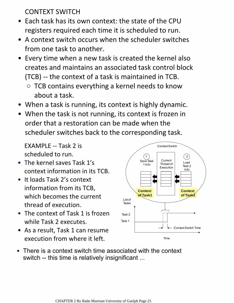
EXAMPLE ‐‐ Task 2 is scheduled to run.The kernel saves Task 1’s context information in its TCB.
•
It loads Task 2’s context information from its TCB, which becomes the current thread of execution.
•
The context of Task 1 is frozen while Task 2 executes.
•
As a result, Task 1 can resume execution from where it left.
•
There is a context switch time associated with the context switch -- this time is relatively insignificant ...
•
CHAPTER 2 By Radu Muresan University of Guelph Page 25
EXAMPLE OF CONTEXT SWITCH IN uC/OS‐II
Task #1 Task #2 Task #3stack stack stack
Status
SP
Priority
Task Control BlockStatus
SP
Priority
Task Control BlockStatus
SP
Priority
Task Control Block
SP
CPU Registers
Context
Memory
CPU
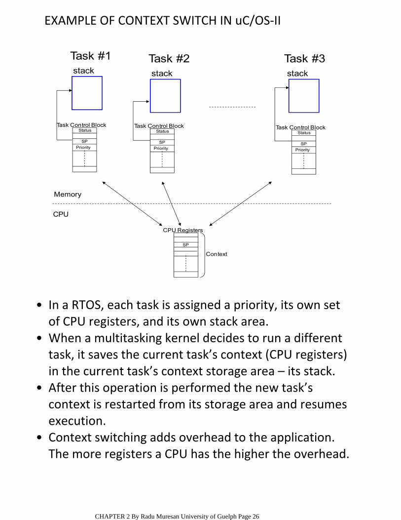
In a RTOS, each task is assigned a priority, its own set of CPU registers, and its own stack area.
•
When a multitasking kernel decides to run a different task, it saves the current task’s context (CPU registers) in the current task’s context storage area – its stack.
•
After this operation is performed the new task’s context is restarted from its storage area and resumes execution.
•
Context switching adds overhead to the application. The more registers a CPU has the higher the overhead.
•
CHAPTER 2 By Radu Muresan University of Guelph Page 26
OSTCBCur(1)
OSTCBHightRdy
(3)
OS_TCB OS_TCB
LOW MEMORY
HIGH MEMORY
LOW MEMORY
HIGH MEMORY
R1R2R3R4
PC
PSW
SP
R1R2R3
R4
PC
PSW
Stack Growth
CPU(2)
(4)
(5)
Low Priority Task High Priority Task
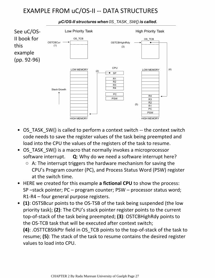
μC/OS-II structures when 0S_TASK_SW() is called.
EXAMPLE FROM uC/OS‐II ‐‐ DATA STRUCTURES
OS_TASK_SW() is called to perform a context switch ‐‐ the context switch code needs to save the register values of the task being preempted and load into the CPU the values of the registers of the task to resume.
•
A: The interrupt triggers the hardware mechanism for saving the CPU’s Program counter (PC), and Process Status Word (PSW) register at the switch time.
○
OS_TASK_SW() is a macro that normally invokes a microprocessor software interrupt. Q: Why do we need a software interrupt here?
•
HERE we created for this example a fictional CPU to show the process: SP –stack pointer; PC – program counter; PSW – processor status word; R1‐R4 – four general purpose registers.
•
(1): OSTSBcur points to the OS‐TSB of the task being suspended (the low priority task); (2): The CPU’s stack pointer register points to the current top‐of‐stack of the task being preempted; (3): OSTCBHighRdy points to the OS‐TCB task that will be executed after context switch; (4): .OSTTCBStkPtr field in OS_TCB points to the top‐of‐stack of the task to resume; (5): The stack of the task to resume contains the desired register values to load into CPU.
•
See uC/OS‐II book for this example (pp. 92‐96)
CHAPTER 2 By Radu Muresan University of Guelph Page 27

Examplefrom uC/OS-II LOW MEMORY
HIGH MEMORY
R1R2R3
R4
PC
PSW
LOW MEMORY
HIGH MEMORY
R1R2R3R4
PCPSW
R1R2R3R4
PC
PSW
SP
CPU
(2)
(1)
(3)
Stack Growth
(3)
OSTCBCur
OS_TCB
OSTCBHightRdy
OS_TCB
Low Priority Task High Priority Task
Saving the current task’s context.
Step (1): Calling OS_TASK_SW() invokes the software interrupt instruction, which forces the processor to save the current value of PSW and the PC unto the current task’s stack.
•
The processor then vectors to the software interrupt handler which is responsible for completing the remaining steps of the context switch.
•
Step (2): The software interrupt handler starts by saving the general purpose registers R1, R2, R3, and R4 in this order.
•
Step (3): The stack pointer register is then saved into the current task’s OS_TCB. At this point, both the CPU’s SP register and OSTCBcur ‐> OSTCBStkPtr are pointing to the same location into the current task’s stack.
•
CHAPTER 2 By Radu Muresan University of Guelph Page 28
Examplefrom uC/OS-II
LOW MEMORY
HIGH MEMORY
R1R2R3
R4
PC
PSW
OS_TCB
OSTCBHightRdy
OSTCBCur
R1R2R3R4
PC
PSW
SP
CPULOW MEMORY
R1R2R3R4
PCPSW
(3)
Stack Growth
OS_TCB
Low Priority Task
(4)
(4)
(3)
(2)
(1)
HIGH MEMORY
High Priority Task
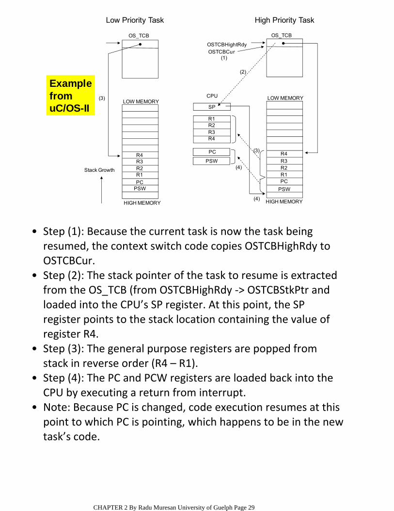
Step (1): Because the current task is now the task being resumed, the context switch code copies OSTCBHighRdy to OSTCBCur.
•
Step (2): The stack pointer of the task to resume is extracted from the OS_TCB (from OSTCBHighRdy ‐> OSTCBStkPtr and loaded into the CPU’s SP register. At this point, the SP register points to the stack location containing the value of register R4.
•
Step (3): The general purpose registers are popped from stack in reverse order (R4 – R1).
•
Step (4): The PC and PCW registers are loaded back into the CPU by executing a return from interrupt.
•
Note: Because PC is changed, code execution resumes at this point to which PC is pointing, which happens to be in the new task’s code.
•
CHAPTER 2 By Radu Muresan University of Guelph Page 29
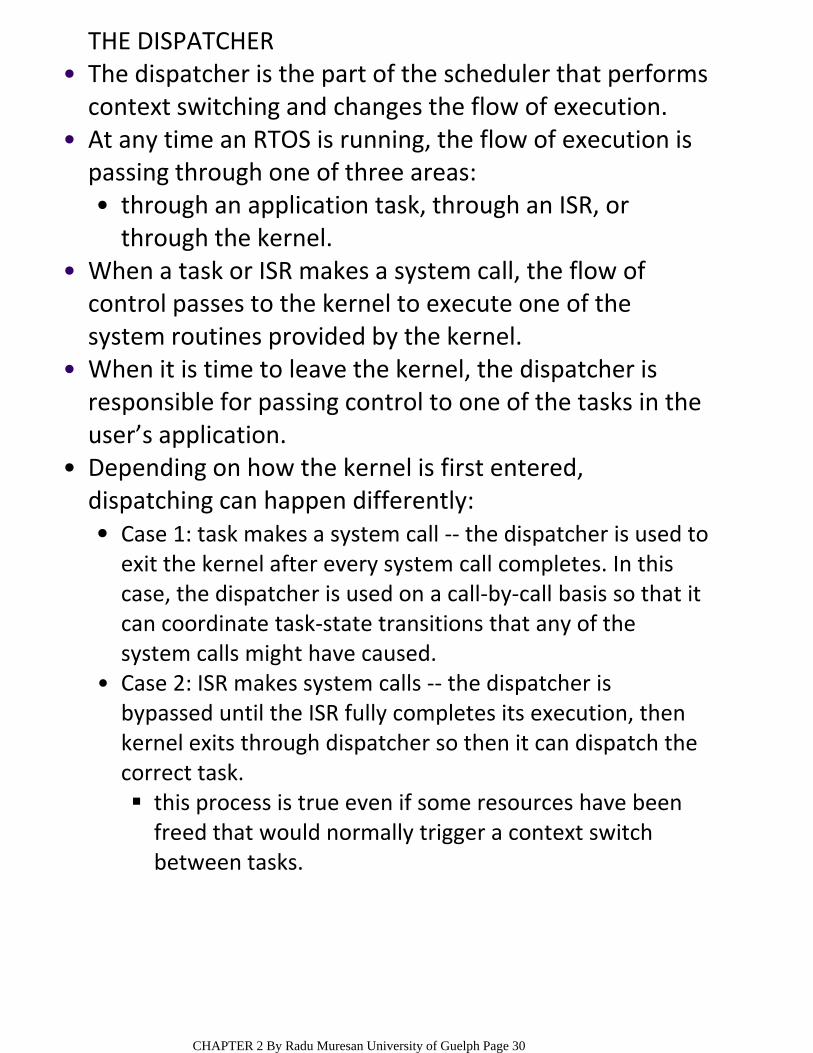
THE DISPATCHERThe dispatcher is the part of the scheduler that performs context switching and changes the flow of execution.
•
through an application task, through an ISR, or through the kernel.
•
At any time an RTOS is running, the flow of execution is passing through one of three areas:
•
When a task or ISR makes a system call, the flow of control passes to the kernel to execute one of the system routines provided by the kernel.
•
When it is time to leave the kernel, the dispatcher is responsible for passing control to one of the tasks in the user’s application.
•
Case 1: task makes a system call ‐‐ the dispatcher is used to exit the kernel after every system call completes. In this case, the dispatcher is used on a call‐by‐call basis so that it can coordinate task‐state transitions that any of the system calls might have caused.
•
this process is true even if some resources have been freed that would normally trigger a context switch between tasks.
Case 2: ISR makes system calls ‐‐ the dispatcher is bypassed until the ISR fully completes its execution, then kernel exits through dispatcher so then it can dispatch the correct task.
•
Depending on how the kernel is first entered, dispatching can happen differently:
•
CHAPTER 2 By Radu Muresan University of Guelph Page 30
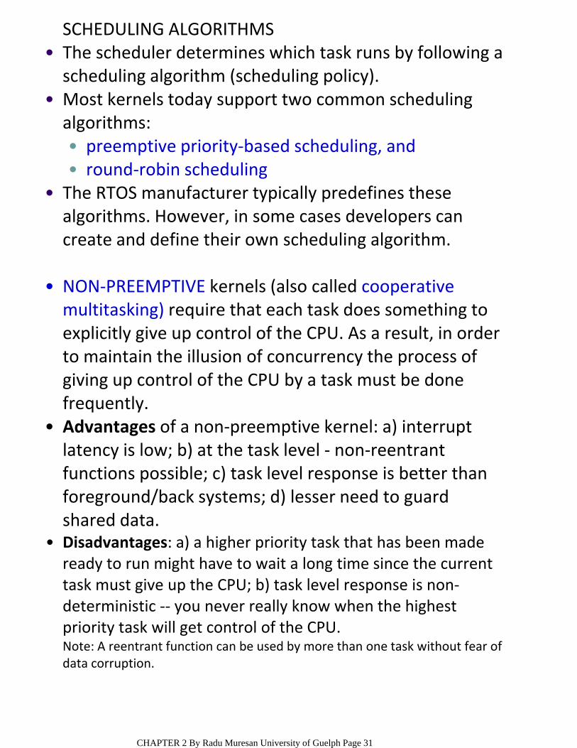
SCHEDULING ALGORITHMSThe scheduler determines which task runs by following a scheduling algorithm (scheduling policy).
•
preemptive priority‐based scheduling, and•round‐robin scheduling•
Most kernels today support two common scheduling algorithms:
•
The RTOS manufacturer typically predefines these algorithms. However, in some cases developers can create and define their own scheduling algorithm.
•
NON‐PREEMPTIVE kernels (also called cooperative multitasking) require that each task does something to explicitly give up control of the CPU. As a result, in order to maintain the illusion of concurrency the process of giving up control of the CPU by a task must be done frequently.
•
Advantages of a non‐preemptive kernel: a) interrupt latency is low; b) at the task level ‐ non‐reentrant functions possible; c) task level response is better than foreground/back systems; d) lesser need to guard shared data.
•
Disadvantages: a) a higher priority task that has been made ready to run might have to wait a long time since the current task must give up the CPU; b) task level response is non‐deterministic ‐‐ you never really know when the highest priority task will get control of the CPU.
•
Note: A reentrant function can be used by more than one task without fear of data corruption.
CHAPTER 2 By Radu Muresan University of Guelph Page 31

PREEMPTIVE KERNELSA preemptive kernel is used when system responsiveness is important ‐‐most commercial RT kernels are preemptive.
•
when a task makes a higher priority task ready to run, the current task is preempted and the higher priority task is immediately given control of CPU.
○
if an ISR makes a higher priority task ready, when the ISR completes, the interrupted task is suspended, and the new higher priority task runs.
○
The highest priority task ready to run is always given control of the CPU:
•
Task 1
Task 2
Task 3
Task 1
Task 2
High
Low
Taskpriority
preemption task completion
If a task with a priority higher than the current task becomes ready to run, the kernel immediately saves the current task's context in its TCB and switches to the higher priority task.
•
With preemptive kernels, execution of the highest priority task becomes deterministic. As a result, task‐level time is thus minimized.
•
CHAPTER 2 By Radu Muresan University of Guelph Page 32
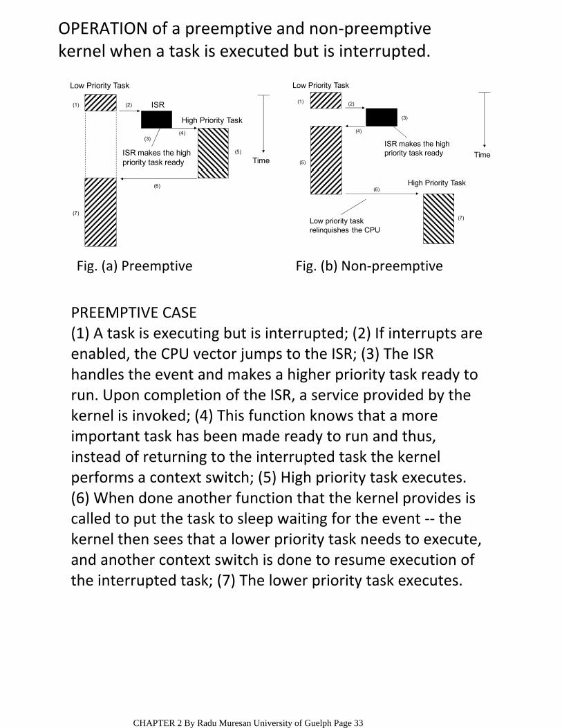
OPERATION of a preemptive and non‐preemptive kernel when a task is executed but is interrupted.
TimeISR makes the highpriority task ready
High Priority Task
Low Priority Task
(1) (2)
(3)(4)
(5)
(6)
(7)
ISR
Low priority taskrelinquishes the CPU
ISR makes the highpriority task ready
High Priority Task
Time
Low Priority Task
(1) (2)
(3)
(4)
(5)
(6)
(7)
Fig. (a) Preemptive Fig. (b) Non‐preemptive
PREEMPTIVE CASE(1) A task is executing but is interrupted; (2) If interrupts are enabled, the CPU vector jumps to the ISR; (3) The ISR handles the event and makes a higher priority task ready to run. Upon completion of the ISR, a service provided by the kernel is invoked; (4) This function knows that a more important task has been made ready to run and thus, instead of returning to the interrupted task the kernel performs a context switch; (5) High priority task executes. (6) When done another function that the kernel provides is called to put the task to sleep waiting for the event ‐‐ the kernel then sees that a lower priority task needs to execute, and another context switch is done to resume execution of the interrupted task; (7) The lower priority task executes.
CHAPTER 2 By Radu Muresan University of Guelph Page 33

OTHER FEATURES OF PREEMPTIVE KERNELS
Real‐time kernels generally support 256 priority levels, in which 0 is the highest and 255 is the lowest (some kernels have 255 as the highest priority and 0 as the lowest)
•
Task’s priority is assigned when they are created. ○In preemptive kernels each task has a priority•
The task’s priority can be changed dynamically using kernel‐provided calls ‐‐ this allows an embedded application the flexibility to adjust to external events as they occur creating a true real‐time, responsive system.
•
the execution of the highest priority task is deterministic.
○
task‐level response is minimized.○
Advantages of preemptive kernels:•
As a result, corruption of data can occur if a higher priority task preempts a lower priority one.
○
Application code using preemptive kernel should not use non‐reentrant functions unless exclusive access to these functions is controlled through mutual semaphores because both a low and a high priority task can use a common function.
•
CHAPTER 2 By Radu Muresan University of Guelph Page 34
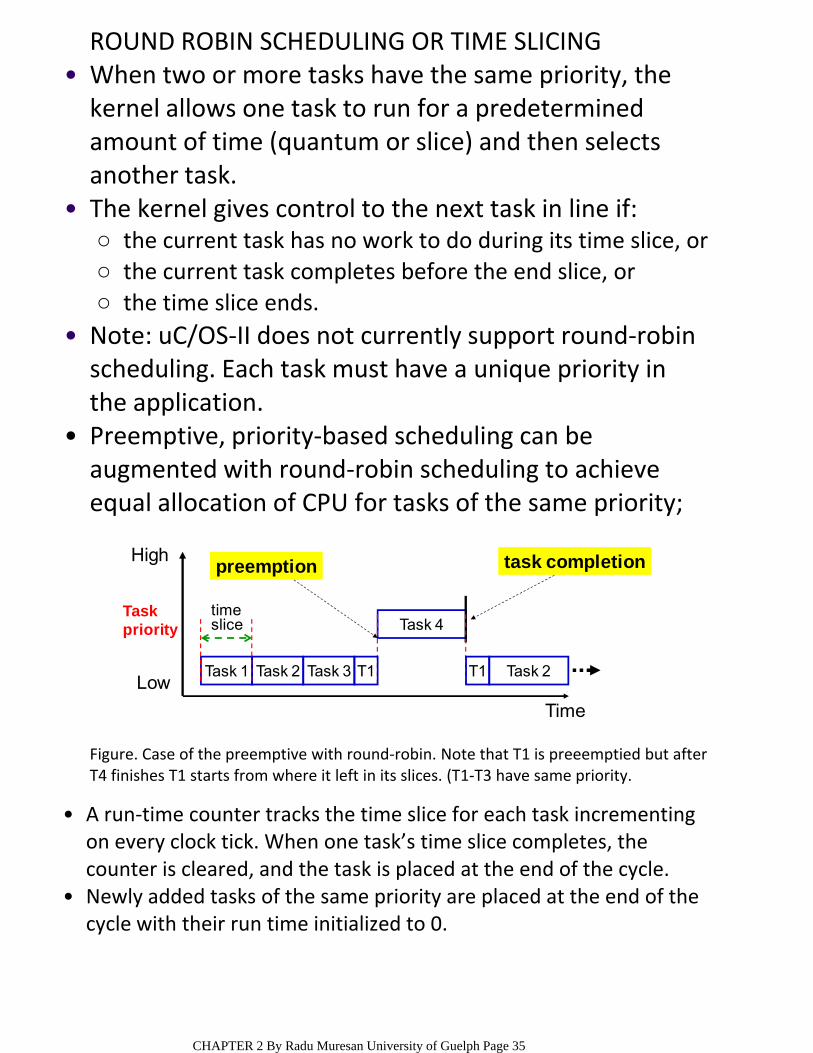
ROUND ROBIN SCHEDULING OR TIME SLICING When two or more tasks have the same priority, the kernel allows one task to run for a predetermined amount of time (quantum or slice) and then selects another task.
•
the current task has no work to do during its time slice, or○the current task completes before the end slice, or ○the time slice ends.○
The kernel gives control to the next task in line if: •
Note: uC/OS‐II does not currently support round‐robin scheduling. Each task must have a unique priority in the application.
•
Preemptive, priority‐based scheduling can be augmented with round‐robin scheduling to achieve equal allocation of CPU for tasks of the same priority;
•
Task 1
Task 4
Task 2
High
Low
Taskpriority
preemption task completion
Task 2 Task 3 T1 T1
timeslice
Time
A run‐time counter tracks the time slice for each task incrementing on every clock tick. When one task’s time slice completes, the counter is cleared, and the task is placed at the end of the cycle.
•
Newly added tasks of the same priority are placed at the end of the cycle with their run time initialized to 0.
•
Figure. Case of the preemptive with round‐robin. Note that T1 is preeemptied but after T4 finishes T1 starts from where it left in its slices. (T1‐T3 have same priority.
CHAPTER 2 By Radu Muresan University of Guelph Page 35
OBJECTSKernel objects are special constructs that form the building blocks for application development for real‐time embedded systems;
•
Tasks – are concurrent and independent threads of execution that can compete for CPU execution time
○
Semaphores – are token‐like objects that can be incremented or decremented by tasks for synchronization or mutual exclusion
○
Message Queues – are buffer‐like data structures that can be used for synchronization, mutual exclusion, and data exchange.
○
The most common RTOS kernel objects are: •
... Q: Combining these basic kernel objects (and others) what common real‐time design problems can be solved??
SERVICESAlong with objects most kernels provide services that help developers create applications for real‐time embedded systems.
•
The most common services found comprise sets of API (Application Program Interface) calls that can be used to perform operations on kernel objects or can be used in general to facilitate timer management, interrupt handling, device I/O, and memory management.
•
CHAPTER 2 By Radu Muresan University of Guelph Page 36
KEY CHARACTERISTICS OF AN RTOS
Reliability ‐‐ depending on the application, the system might need to operate for long periods without human intervention.
○
Predictability ‐‐meeting time requirements is key to real‐time embedded systems ‐‐ the term deterministic describes RTOSs with predictable behavior, in which the completion of OS calls occurs within known timeframes.
○
Performance ‐‐ this requirement dictates that the embedded system must perform fast enough to fulfill its timing requirements.
○
Compactness ‐‐ application design constraints and cost constraints help determine how compact and embedded system needs to be.
○
Scalability ‐‐ because RTOSs can be used in a wide variety of applications, they must be able to scale up or down to meet application‐specific requirements.
○
Applications define the requirements of its underlying RTOS. Some of the more common ones are:
•
CHAPTER 2 By Radu Muresan University of Guelph Page 37
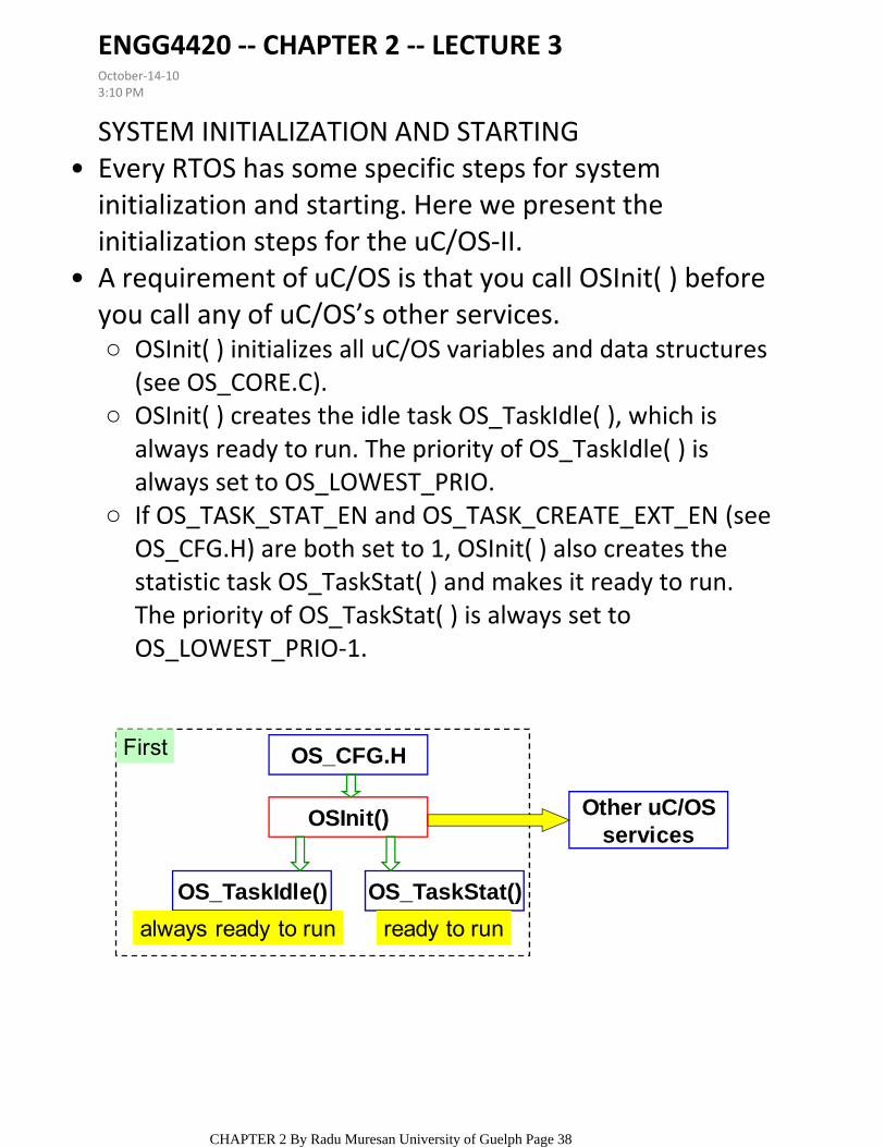
SYSTEM INITIALIZATION AND STARTINGEvery RTOS has some specific steps for system initialization and starting. Here we present the initialization steps for the uC/OS‐II.
•
OSInit( ) initializes all uC/OS variables and data structures (see OS_CORE.C).
○
OSInit( ) creates the idle task OS_TaskIdle( ), which is always ready to run. The priority of OS_TaskIdle( ) is always set to OS_LOWEST_PRIO.
○
If OS_TASK_STAT_EN and OS_TASK_CREATE_EXT_EN (see OS_CFG.H) are both set to 1, OSInit( ) also creates the statistic task OS_TaskStat( ) and makes it ready to run. The priority of OS_TaskStat( ) is always set to OS_LOWEST_PRIO‐1.
○
A requirement of uC/OS is that you call OSInit( ) before you call any of uC/OS’s other services.
•
OSInit() Other uC/OSservices
OS_TaskIdle() OS_TaskStat()
OS_CFG.H
always ready to run ready to run
First
ENGG4420 ‐‐ CHAPTER 2 ‐‐ LECTURE 3October‐14‐103:10 PM
CHAPTER 2 By Radu Muresan University of Guelph Page 38
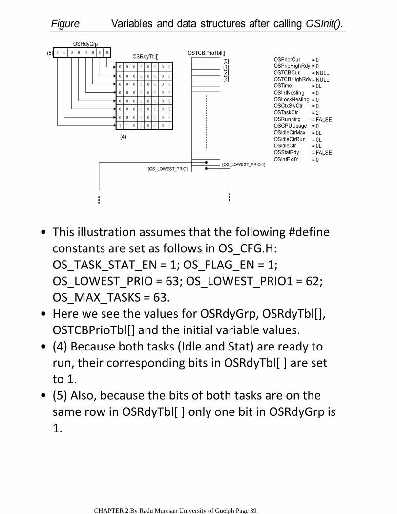
This illustration assumes that the following #define constants are set as follows in OS_CFG.H: OS_TASK_STAT_EN = 1; OS_FLAG_EN = 1;
•
OS_LOWEST_PRIO = 63; OS_LOWEST_PRIO1 = 62; OS_MAX_TASKS = 63.Here we see the values for OSRdyGrp, OSRdyTbl[], OSTCBPrioTbl[] and the initial variable values.
•
(4) Because both tasks (Idle and Stat) are ready to run, their corresponding bits in OSRdyTbl[ ] are set to 1.
•
(5) Also, because the bits of both tasks are on the same row in OSRdyTbl[ ] only one bit in OSRdyGrp is 1.
•
00000011
00000000
00000000
00000000
00000000
00000000
00000000
00000000
OSRdyTbl[]
OSRdyGrp
00000001 OSTCBPrioTbll[]
[1][0]
[2][3]
[OS_LOWEST_PRIO-1][OS_LOWEST_PRIO]
(4)
(5)OSPriorCurOSPrioHighRdyOSTCBCurOSTCBHighRdy OSTime OSIntNestingOSLockNestingOSCtxSwCtr OSTaskCtrOSRunningOSCPUUsage OSIdleCtrMax OSIdleCtrRun OSIdleCtrOSStatRdyOSIntExitY
= 0= 0= NULL= NULL= 0L= 0= 0= 0= 2= FALSE= 0= 0L= 0L= 0L= FALSE= 0
Figure Variables and data structures after calling OSInit().
CHAPTER 2 By Radu Muresan University of Guelph Page 39
OSTCBStkPtrOSTCBExtPtr
OSTCBStkBottomOSTCBStkSize
OSTCBOpt
OSTCBId
OSTCBNextOSTCBPrev
OSTCBEventPtr
OSTCBMsg
OSTCBFlagNodeOSTCBFlagsRdy
OSTCBDlyOSTCBStatOSTCBPrio
OSTCBXOSTCBYOSTCBBitX OSTCBBitYOSTCBDelReq
= NULL
= stk_size
= OS_TASK_OPT_STK_CHK| OS_TASK_OPT_STK_CLR= OS_LOWEST_PRIO-1
= NULL
= NULL
= NULL= 0
= 0= OS_STAT_RDY= OS_LOWEST_PRIO-1
= 6= 7= 0x40= 0x80= FALSE
TaskStack
OS_TCBOf
OS_TaskStat()
OSTCBStkPtrOSTCBExtPtr
OSTCBStkBottomOSTCBStkSize
OSTCBOpt
OSTCBId
OSTCBNextOSTCBPrev
OSTCBEventPtr
OSTCBMsg
OSTCBFlagNodeOSTCBFlagsRdy
OSTCBDlyOSTCBStatOSTCBPrio
OSTCBXOSTCBYOSTCBBitX OSTCBBitYOSTCBDelReq
= NULL
= stk_size
= OS_TASK_OPT_STK_CHK| OS_TASK_OPT_STK_CLR= OS_LOWEST_PRIO
= NULL
= NULL
= NULL= 0
= 0= OS_STAT_RDY= OS_LOWEST_PRIO
= 7= 7= 0x80= 0x80= FALSE
TaskStack
OS_TCBOf
OS_TaskIdle()
(2)OSTCBList
(3)(1) (3)0
0
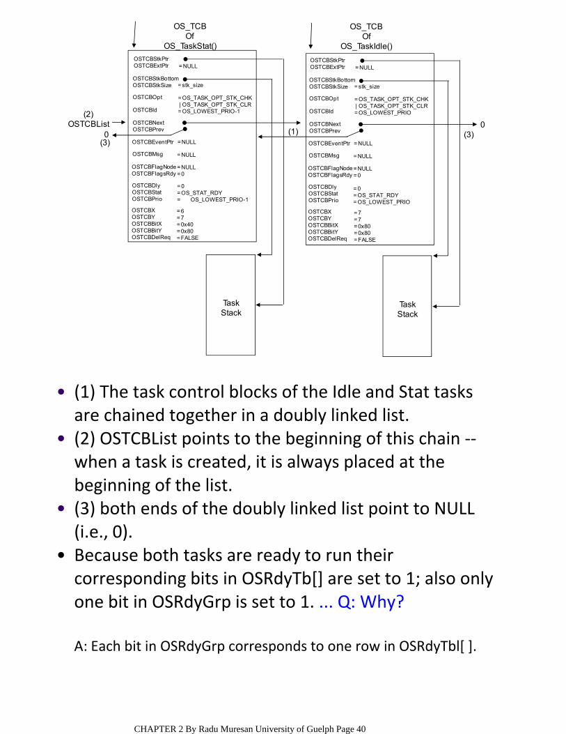
(1) The task control blocks of the Idle and Stat tasks are chained together in a doubly linked list.
•
(2) OSTCBList points to the beginning of this chain ‐‐when a task is created, it is always placed at the beginning of the list.
•
(3) both ends of the doubly linked list point to NULL (i.e., 0).
•
Because both tasks are ready to run their corresponding bits in OSRdyTb[] are set to 1; also only one bit in OSRdyGrp is set to 1. ... Q: Why?
•
A: Each bit in OSRdyGrp corresponds to one row in OSRdyTbl[ ].
CHAPTER 2 By Radu Muresan University of Guelph Page 40
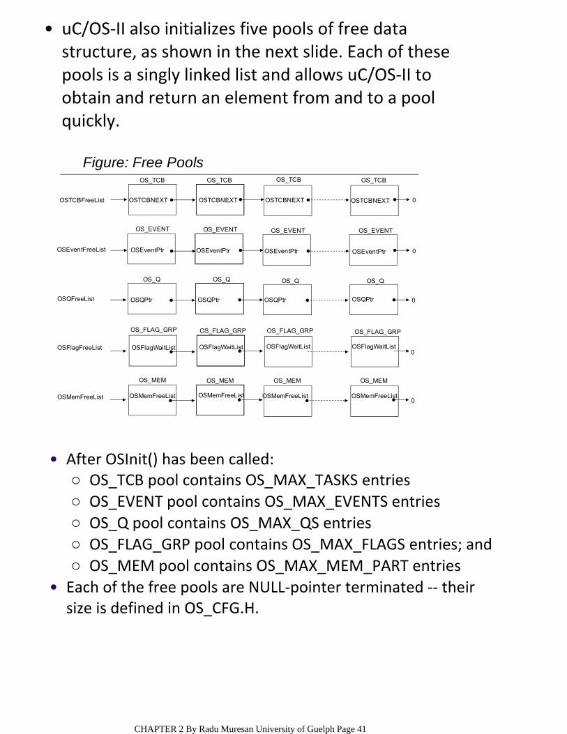
uC/OS‐II also initializes five pools of free data structure, as shown in the next slide. Each of these pools is a singly linked list and allows uC/OS‐II to obtain and return an element from and to a pool quickly.
•
0
0
0
0
0
OS_TCB OS_TCB OS_TCB OS_TCB
OS_EVENT OS_EVENT OS_EVENT OS_EVENT
OS_QOS_QOS_QOS_Q
OS_FLAG_GRP OS_FLAG_GRP OS_FLAG_GRP OS_FLAG_GRP
OS_MEM OS_MEM OS_MEM OS_MEM
OSTCBNEXT OSTCBNEXT OSTCBNEXT OSTCBNEXT
OSEventPtr OSEventPtr OSEventPtr OSEventPtr
OSQPtr OSQPtr OSQPtr OSQPtr
OSFlagWaitList OSFlagWaitList OSFlagWaitList OSFlagWaitList
OSMemFreeList OSMemFreeList OSMemFreeList OSMemFreeList
OSFlagFreeList
OSMemFreeList
OSQFreeList
OSEventFreeList
OSTCBFreeList
Figure: Free Pools
OS_TCB pool contains OS_MAX_TASKS entries ○OS_EVENT pool contains OS_MAX_EVENTS entries○OS_Q pool contains OS_MAX_QS entries○OS_FLAG_GRP pool contains OS_MAX_FLAGS entries; and○OS_MEM pool contains OS_MAX_MEM_PART entries○
After OSInit() has been called:•
Each of the free pools are NULL‐pointer terminated ‐‐ their size is defined in OS_CFG.H.
•
CHAPTER 2 By Radu Muresan University of Guelph Page 41
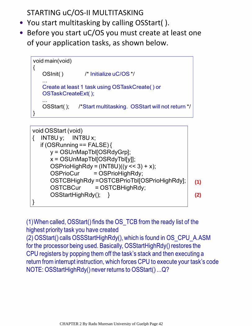
STARTING uC/OS‐II MULTITASKINGYou start multitasking by calling OSStart( ).•Before you start uC/OS you must create at least one of your application tasks, as shown below.
•
void main(void){
OSInit( ) /* Initialize uC/OS */...Create at least 1 task using OSTaskCreate( ) orOSTaskCreateExt( );...OSStart( ); /*Start multitasking. OSStart will not return */
}
void OSStart (void){ INT8U y; INT8U x;
if (OSRunning == FALSE) {y = OSUnMapTbl[OSRdyGrp];x = OSUnMapTbl[OSRdyTbl[y]];OSPrioHighRdy = (INT8U)((y << 3) + x);OSPrioCur = OSPrioHighRdy;OSTCBHighRdy =OSTCBPrioTbl[OSPrioHighRdy];OSTCBCur = OSTCBHighRdy;OSStartHighRdy(); }
}
(1)
(2)
(1)When called, OSStart() finds the OS_TCB from the ready list of thehighest priority task you have created(2) OSStart() calls OSSStartHighRdy(), which is found in OS_CPU_A.ASMfor the processor being used. Basically, OSStartHighRdy() restores theCPU registers by popping them off the task’s stack and then executing areturn from interrupt instruction, which forces CPU to execute your task’s codeNOTE: OSStartHighRdy() never returns to OSStart() ...Q?
CHAPTER 2 By Radu Muresan University of Guelph Page 42
created task
task stack task stack task stack
OSTCBStkPtrOSTCBExtPtr
OSTCBStkBottomOSTCBStkSizeOSTCBOpt
OSTCBIdOSTCBNextOSTCBPrev
OSTCBEventPtr
OSTCBMsg
OSTCBFlagNodeOSTCBFlagsRdyOSTCBDlyOSTCBStatOSTCBPrioOSTCBXOSTCBYOSTCBBitX OSTCBBitYOSTCBDelReq
= NULL
= stk_size
= OS_TASK_OPT_STK_CHK
| OS_TASK_OPT_STK_CLR
= 6
= NULL
= NULL
= NULL= 0
= 0= OS_STAT_RDY= 6= 6= 1= 0x40= 0x01= FALSE
OS_TCBOf
First App. Task()
0
OSTCBStkPtrOSTCBExtPtrOSTCBStkBottomOSTCBStkSizeOSTCBOpt
OSTCBIdOSTCBNextOSTCBPrevOSTCBEventPtr
OSTCBMsg
OSTCBFlagNodeOSTCBFlagsRdyOSTCBDlyOSTCBStatOSTCBPrioOSTCBXOSTCBYOSTCBBitX OSTCBBitYOSTCBDelReq
= NULL
= stk_size
= OS_TASK_OPT_STK_CHK| OS_TASK_OPT_STK_CLR= OS_LOWEST_PRIO-1
= NULL
= NULL
= NULL= 0= 0= OS_STAT_RDY= OS_LOWEST_PRIO-1= 6= 7= 0x40= 0x80= FALSE
OS_TCBOf
OS_TaskStat()
OSTCBCurOSTCBHighRdy
OSTCBList
OSTCBStkPtrOSTCBExtPtr
OSTCBStkBottomOSTCBStkSize
OSTCBOpt
OSTCBId
OSTCBNextOSTCBPrev
OSTCBEventPtr
OSTCBMsg
OSTCBFlagNodeOSTCBFlagsRdy
OSTCBDlyOSTCBStatOSTCBPrioOSTCBXOSTCBYOSTCBBitX OSTCBBitYOSTCBDelReq
= NULL
= stk_size
= OS_TASK_OPT_STK_CHK| OS_TASK_OPT_STK_CLR= OS_LOWEST_PRIO
= NULL
= NULL
= NULL= 0
= 0= OS_STAT_RDY= OS_LOWEST_PRIO= 7= 7= 0x80= 0x80= FALSE
OS_TCBOf
OS_TaskIdle()
0
[OS_LOWEST_PRIO][OS_LOWEST_PRIO-1]
[0][1][2][3][4][5][6][7]
0 1 0 0 0 0 0 00 0 0 0 0 0 0 00 0 0 0 0 0 0 00 0 0 0 0 0 0 0
0 0 0 0 0 0 0 00 0 0 0 0 0 0 0
0 0 0 0 0 0 0 01 1 0 0 0 0 0 0
1 0 0 0 0 0 0 1
OSRdyGrp
OSRdyTbl[]
OSTCBPrioTbl[] OSPrioCurOSPrioHighRdy
OSTimeOSIntNestingOSlockingNestingOSCtxSwCtrOSTaskCtrOSRunningOSCPUUsageOSIdleCtrMaxOSIdleCtrRunOSIdleCtrOSStatRdyOSIntExitY
= 6= 6
= 0L= 0= 0= 0= 3= True= 0= 0L= 0L= 0L= False= 0
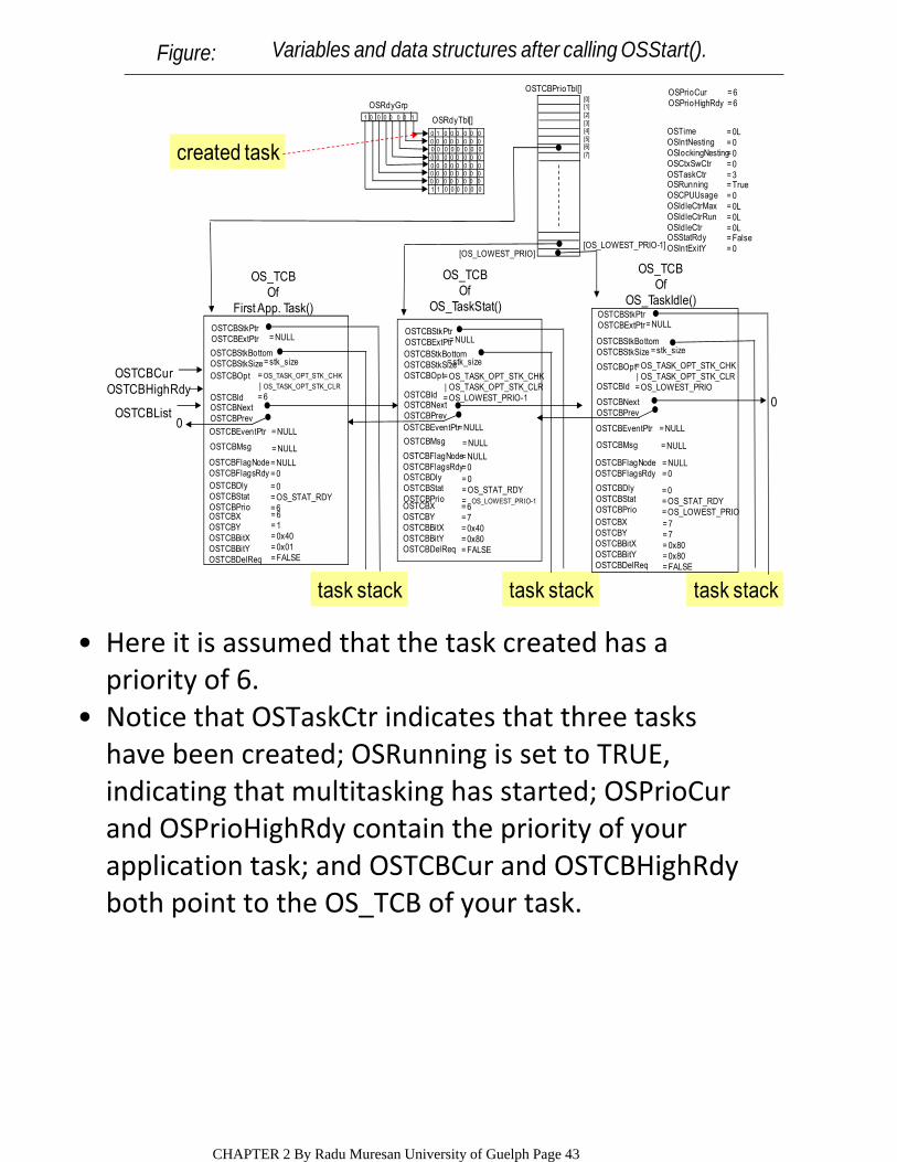
Figure: Variables and data structures after calling OSStart().
Here it is assumed that the task created has a priority of 6.
•
Notice that OSTaskCtr indicates that three tasks have been created; OSRunning is set to TRUE, indicating that multitasking has started; OSPrioCur and OSPrioHighRdy contain the priority of your application task; and OSTCBCur and OSTCBHighRdy both point to the OS_TCB of your task.
•
CHAPTER 2 By Radu Muresan University of Guelph Page 43
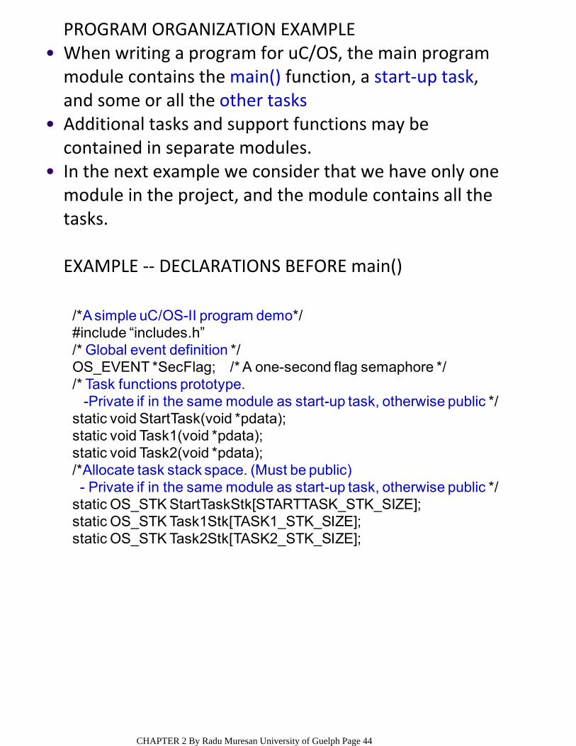
PROGRAM ORGANIZATION EXAMPLEWhen writing a program for uC/OS, the main program module contains the main() function, a start‐up task, and some or all the other tasks
•
Additional tasks and support functions may be contained in separate modules.
•
In the next example we consider that we have only one module in the project, and the module contains all the tasks.
•
EXAMPLE ‐‐ DECLARATIONS BEFORE main()
/*A simple uC/OS-II program demo*/#include “includes.h”/* Global event definition */OS_EVENT *SecFlag; /* A one-second flag semaphore *//* Task functions prototype.
-Private if in the same module as start-up task, otherwise public */static void StartTask(void *pdata);static void Task1(void *pdata);static void Task2(void *pdata);/*Allocate task stack space. (Must be public)- Private if in the same module as start-up task, otherwise public */
static OS_STK StartTaskStk[STARTTASK_STK_SIZE];static OS_STK Task1Stk[TASK1_STK_SIZE];static OS_STK Task2Stk[TASK2_STK_SIZE];
CHAPTER 2 By Radu Muresan University of Guelph Page 44
DECLARATIONS EXPLAINEDThe module starts by including the master header file include.h (to be presented later).
•
In this case, there is a single event, SecFlag, and three tasks, StartTask, Task1, and Task2.
○
Notice that the task functions are declared as private functions. “static” declaration indicates private to the module file (static variables are local but permanent – remain in existence). This is because task functions should never actually be called by another function. They are executed by the kernel, which knows about each task through the OSTaskCreate() service routine.
○
The event objects are handled like normal C resources. They may be private if only used in the current module, or they must be public if used by a task in another module.
○
Next, the program defines the uC/OS events and task functions contained in the module.
•
The size of each stack is defined in the include.h header file. The stack space should always be allocated in the same module as the task, so it too can be declared as a private resource.
○
In a preemptive kernel each task uses its own stack space. So after the task functions are declared, the stack space for each task is allocated.
•
CHAPTER 2 By Radu Muresan University of Guelph Page 45
EXAMPLE ‐‐MAIN()
Recall that main() is the function called after the system is reset and the start‐up code is completed.
○
Therefore, the main() it is the entry point for our application code.
○
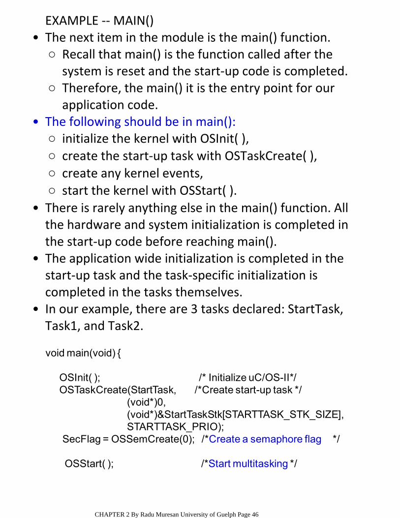
The next item in the module is the main() function.•
initialize the kernel with OSInit( ),○create the start‐up task with OSTaskCreate( ),○create any kernel events,○start the kernel with OSStart( ).○
The following should be in main():•
There is rarely anything else in the main() function. All the hardware and system initialization is completed in the start‐up code before reaching main().
•
The application wide initialization is completed in the start‐up task and the task‐specific initialization is completed in the tasks themselves.
•
In our example, there are 3 tasks declared: StartTask, Task1, and Task2.
•
void main(void) {
OSInit( ); /* Initialize uC/OS-II*/OSTaskCreate(StartTask, /*Create start-up task */
(void*)0,(void*)&StartTaskStk[STARTTASK_STK_SIZE],STARTTASK_PRIO);
SecFlag = OSSemCreate(0); /*Create a semaphore flag */
OSStart( ); /*Start multitasking */
CHAPTER 2 By Radu Muresan University of Guelph Page 46
EXAMPLE ‐‐ START‐UP TASKStartTask() is the start‐up task, which is required in all programs using uC/OS.
•
When we started the kernel in main(), the start‐up task was the only task that had been created. Therefore it is guaranteed that the kernel will run the start‐up task first.
•
In the start‐up task, we need to initialize the uC/OS timer service, create other tasks, and initialize application‐wide resources that were not already initialized in the start‐up code before main().
•
Because, the start‐up task creates other tasks, it must have the highest priority or the kernel may switch to another task before the initialization in the start‐up task is complete.
•
The uC/OS timer is initialized using the service OSTickInit(). The timer must be initialized before any timer services can be used but only after the kernel has been started. Therefore we could not move this to main().
•
The start‐up task is unique because it is meant to run only one time. As we have mentioned most tasks are endless loops. To make sure that the start‐up task is executed only one time, it ends with a trap that calls the OSTaskSuspend() service. OSTaskSuspend() does stop the task, but just in case another task accidentally starts it up again with OSTaskResume(), it is contained in an endless trap.
•
CHAPTER 2 By Radu Muresan University of Guelph Page 47
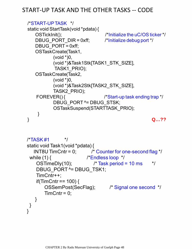
START‐UP TASK AND THE OTHER TASKS ‐‐ CODE
/*START-UP TASK */static void StartTask(void *pdata) {
OSTickInit(); /*Initialize the uC/OS ticker */DBUG_PORT_DIR = 0xff; /*Initialize debug port */DBUG_PORT = 0xff; OSTaskCreate(Task1,
(void *)0, (void *)&Task1Stk[TASK1_STK_SIZE],TASK1_PRIO);
OSTaskCreate(Task2,(void *)0,(void *)&Task2Stk[TASK2_STK_SIZE],TASK2_PRIO);
FOREVER() { /*Start-up task ending trap */DBUG_PORT ̂ = DBUG_STSK;OSTaskSuspend(STARTTASK_PRIO);
}} Q…??
/*TASK #1 */static void Task1(void *pdata) {
INT8U TimCntr = 0; /* Counter for one-second flag */while (1) { /*Endless loop */
OSTimeDly(10); /* Task period = 10 ms */DBUG_PORT ̂ = DBUG_TSK1;TimCntr++;if(TimCntr == 100) {
OSSemPost(SecFlag); /* Signal one second */TimCntr = 0;
}}
}
CHAPTER 2 By Radu Muresan University of Guelph Page 48
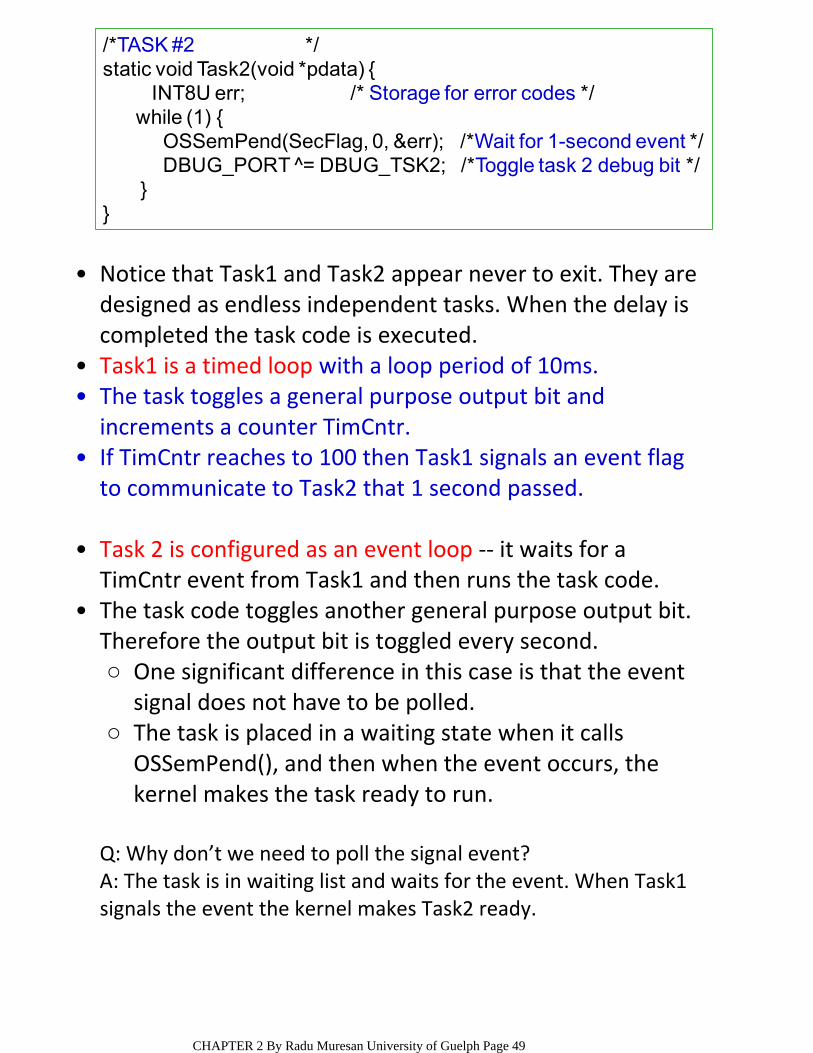
/*TASK #2 */static void Task2(void *pdata) {
INT8U err; /* Storage for error codes */while (1) {
OSSemPend(SecFlag, 0, &err); /*Wait for 1-second event */DBUG_PORT ̂ = DBUG_TSK2; /*Toggle task 2 debug bit */
}}
Notice that Task1 and Task2 appear never to exit. They are designed as endless independent tasks. When the delay is completed the task code is executed.
•
Task1 is a timed loop with a loop period of 10ms. •The task toggles a general purpose output bit and increments a counter TimCntr.
•
If TimCntr reaches to 100 then Task1 signals an event flag to communicate to Task2 that 1 second passed.
•
Task 2 is configured as an event loop ‐‐ it waits for a TimCntr event from Task1 and then runs the task code.
•
One significant difference in this case is that the event signal does not have to be polled.
○
The task is placed in a waiting state when it calls OSSemPend(), and then when the event occurs, the kernel makes the task ready to run.
○
The task code toggles another general purpose output bit. Therefore the output bit is toggled every second.
•
Q: Why don’t we need to poll the signal event?A: The task is in waiting list and waits for the event. When Task1 signals the event the kernel makes Task2 ready.
CHAPTER 2 By Radu Muresan University of Guelph Page 49
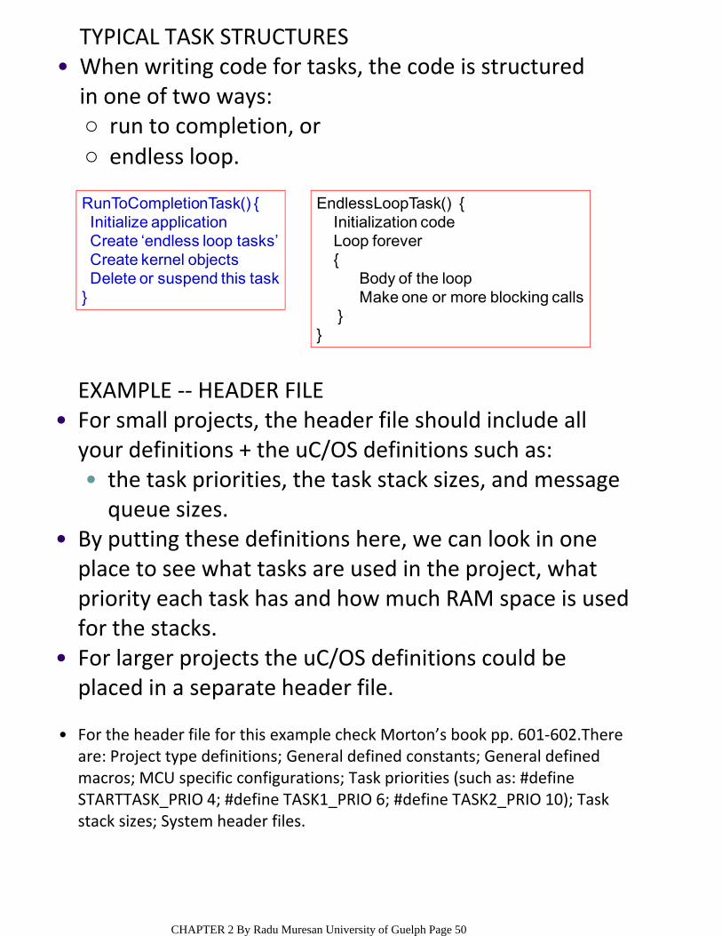
TYPICAL TASK STRUCTURES
run to completion, or ○endless loop.○
When writing code for tasks, the code is structured in one of two ways:
•
RunToCompletionTask() {Initialize applicationCreate ‘endless loop tasks’Create kernel objectsDelete or suspend this task
}
EndlessLoopTask() {Initialization codeLoop forever{
Body of the loopMake one or more blocking calls
}}
EXAMPLE ‐‐ HEADER FILE
the task priorities, the task stack sizes, and message queue sizes.
•
For small projects, the header file should include all your definitions + the uC/OS definitions such as:
•
By putting these definitions here, we can look in one place to see what tasks are used in the project, what priority each task has and how much RAM space is used for the stacks.
•
For larger projects the uC/OS definitions could be placed in a separate header file.
•
For the header file for this example check Morton’s book pp. 601‐602.There are: Project type definitions; General defined constants; General defined macros; MCU specific configurations; Task priorities (such as: #define STARTTASK_PRIO 4; #define TASK1_PRIO 6; #define TASK2_PRIO 10); Task stack sizes; System header files.
•
CHAPTER 2 By Radu Muresan University of Guelph Page 50
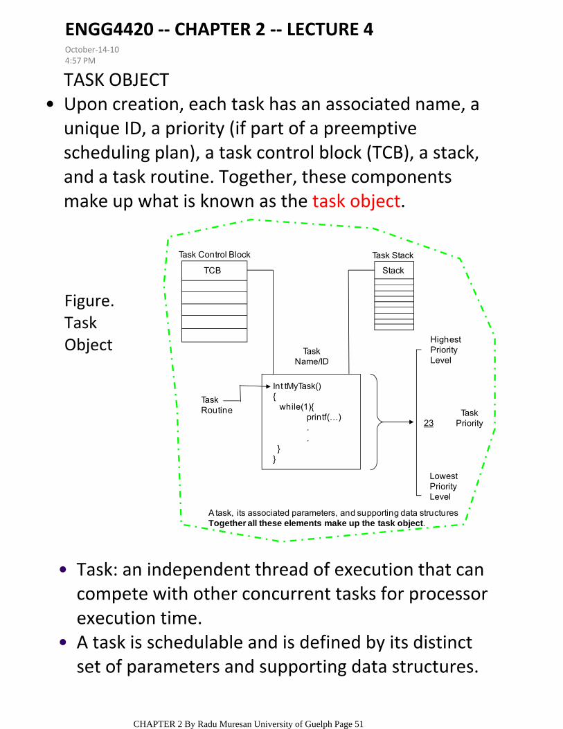
TASK OBJECTUpon creation, each task has an associated name, a unique ID, a priority (if part of a preemptive scheduling plan), a task control block (TCB), a stack, and a task routine. Together, these components make up what is known as the task object.
•
TCB
Task Control Block Task Stack
Stack
HighestPriorityLevel
TaskPriority
LowestPriorityLevel
23
TaskRoutine
TaskName/ID
Int tMyTask(){
while(1){printf(…)..
}}
A task, its associated parameters, and supporting data structuresTogether all these elements make up the task object.
Task: an independent thread of execution that can compete with other concurrent tasks for processor execution time.
•
A task is schedulable and is defined by its distinct set of parameters and supporting data structures.
•
Figure. Task Object
ENGG4420 ‐‐ CHAPTER 2 ‐‐ LECTURE 4October‐14‐104:57 PM
CHAPTER 2 By Radu Muresan University of Guelph Page 51

SYSTEMS TASKSWhen the kernel first starts, it creates its own set of system tasks and allocates the appropriate priority for each from a set of reserved priority levels. The reserved priority levels refer to the priorities used internally by the RTOS for its system tasks.
•
An application should avoid using the reserved priority levels for its tasks because running application tasks at such level may affect the overall system performance or behaviour.
•
For most RTOSs, these reserved priorities are not enforced. The kernel needs its system tasks and their reserved priority levels to operate. These priorities should not be modified.
•
initialization or startup task OSInit() – initializes the system and creates and starts system tasks,
○
It is set to the lowest priority, typically executes in an endless loop, and runs when either no other task can run or when no other task exists, for the sole purpose of using idle processor cycles. The idle task is necessary because the processor executes the instruction to which the program counter register points while it is running. Unless the processor can be suspended, the program counter must still point to valid instructions even when no task exists in the system or when no task can run.
idle task – uses up processor idle cycles ○
logging task – logs system messages, ○exception handling task – handles exceptions, ○debug agent task – allows debugging with a host debugger, and
○
Statistics task ‐‐ generates execution statistics.○
Examples of uC/OS‐II system tasks include: •
CHAPTER 2 By Radu Muresan University of Guelph Page 52

TASK CONTROL BLOCK (TCB)A task control block is a data structure. •
.OSTCBStkPtr: contains a pointer to the current top‐of‐stack for the task
○
.OSTCBStkBottom: is a pointer to the bottom of the task’s stack
○
.OSTCBStkSize: holds the size of the stack in number of elements instead of bytes,
○
.OSTCBId; .OSTCBNext; .OSTCBPrev; .OSTCBEventPtr;
.OSTCBMsg; .OSTCBFlagNode; .OSTCBFlagsRdy;
.OSTCBDly; .OSTCBStat (contains the state of the task); OSTCBPrio (contains the task priority); ...
○
All OS_TCBs reside in RAM. The following are some members of the structure for uC/OS:
•
OS_TCB is initialized by the function OS_TCBInit() when a task is created.
•
Note: A dot at the beginning of a variable indicates that the variable is an element of a structure.
prio: is the task priority;○ptos: is a pointer to the top of stack after the stack frame has been built by OSTaskStkInit() and is stored in the .OSTCBStkPtr field of the OS_TCB
○
pbos: is a pointer to the stack bottom and is stored in the .OSTCBStkBottom field of the OS_TCB
○
id: is the task identifier and is saved in the .OSTCBId field;○stk_size: is the total size of the stack and is saved in the .OSTCBStkSize field of the OS_TCB;
○
pext: is the value to place in the .OSTCBExtPtr field of the OS_TCB;○opt: are the OS_TCB options and are saved in the .OSTCBOpt field.○
OS_TCBInit() is called by either OSTaskCreate() or OSTaskCreateExt(). OS_TCBInit() receives seven arguments:
CHAPTER 2 By Radu Muresan University of Guelph Page 53

void YourTask (void *pdata) /*return type must be declared void*/{
for (;;) { /* you could also use a while (1) statement *//* USER CODE */Call one of uC/OS-II’s services:OSFlagPend();OSMutexPend();OSQPend();OSSemPend();OSTaskDel(OS_PRIO_SELF); OSTaskSuspend(OS_PRIO_SELF);OSTimeDly();OSTimeDlyHMSM();/*USER CODE*/
}) NOTE: A task can delete itself upon completion
A TASK AS AN INFINITE LOOP ‐‐ EXAMPLE
The return type must always be declared void. •
The pointer is a universal vehicle used to pass your task the address of a variable, a structure, or even the address of a function if necessary.
○
An argument is passed to your task code when the task first starts executing. Notice that the argument is a pointer to a void, which allows your application to pass just about any kind of data to your task.
•
Instead of copying the code four times, you can create a task that receives a pointer to a data structure that defines the serial port’s parameters (for example, baud rate, I/O port address, and interrupt vector number) as an argument (See uC/OS examples in the book).
○
It is possible to create many identical tasks, all using the same function (or task body). For example, you could have four asynchronous serial ports that each are managed by their own task. However, the task code is actually identical.
•
CHAPTER 2 By Radu Muresan University of Guelph Page 54

TASK PRIORITIES IN uC/OS‐II
uC/OS can manage up to 64 tasks; •The current version uses two tasks for system use. •It is recommended that you don’t use priorities 0, 1, 2, 3, OS_LOWEST_PRIO‐3, OS_LOWEST_PRIO‐2, OS_LOWEST_PRIO‐1, OS_LOWEST_PRIO
•
OS_LOWEST_PRIO is a #define constant defined in file OS_CFG.H
•
Each task must be assigned a unique priority level. The lower the priority number the higher the priority of the task.
•
uC/OS always executes the highest priority task ready to run, the task priority serve as task ID as well.
•
OSTaskCreate(), or○OSTaskCreateExt() ‐‐ this is an extended version with more features.
○
A task must be created by passing its address along with other arguments to one of two functions:
•
CHAPTER 2 By Radu Muresan University of Guelph Page 55
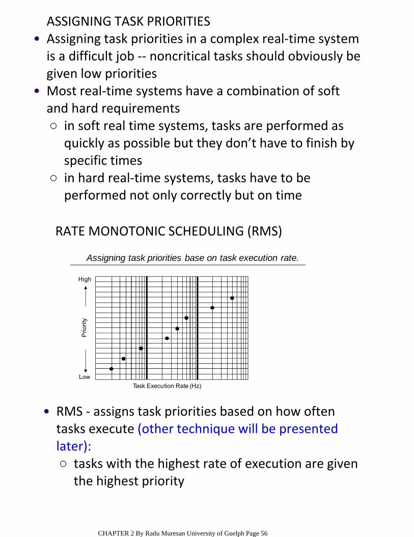
ASSIGNING TASK PRIORITIESAssigning task priorities in a complex real‐time system is a difficult job ‐‐ noncritical tasks should obviously be given low priorities
•
in soft real time systems, tasks are performed as quickly as possible but they don’t have to finish by specific times
○
in hard real‐time systems, tasks have to be performed not only correctly but on time
○
Most real‐time systems have a combination of soft and hard requirements
•P
rio
rity
Low
High
Assigning task priorities base on task execution rate.
Task Execution Rate (Hz)
RATE MONOTONIC SCHEDULING (RMS)
tasks with the highest rate of execution are given the highest priority
○
RMS ‐ assigns task priorities based on how often tasks execute (other technique will be presented later):
•
CHAPTER 2 By Radu Muresan University of Guelph Page 56
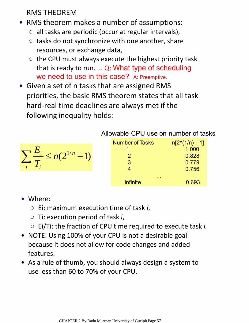
RMS THEOREM
all tasks are periodic (occur at regular intervals),○tasks do not synchronize with one another, share resources, or exchange data,
○
the CPU must always execute the highest priority task that is ready to run. ... Q: What type of scheduling we need to use in this case? A: Preemptive.
○
RMS theorem makes a number of assumptions: •
Given a set of n tasks that are assigned RMS priorities, the basic RMS theorem states that all task hard‐real time deadlines are always met if the following inequality holds:
•
i
n
i
i nT
E)12( /1
Ei: maximum execution time of task i, ○Ti: execution period of task i,○Ei/Ti: the fraction of CPU time required to execute task i.○
Where: •
NOTE: Using 100% of your CPU is not a desirable goal because it does not allow for code changes and added features.
•
As a rule of thumb, you should always design a system to use less than 60 to 70% of your CPU.
•
Allowable CPU use on number of tasksNumber of Tasks n[2^(1/n) – 1]
1 1.0002 0.8283 0.7794 0.756
...infinite 0.693
CHAPTER 2 By Radu Muresan University of Guelph Page 57
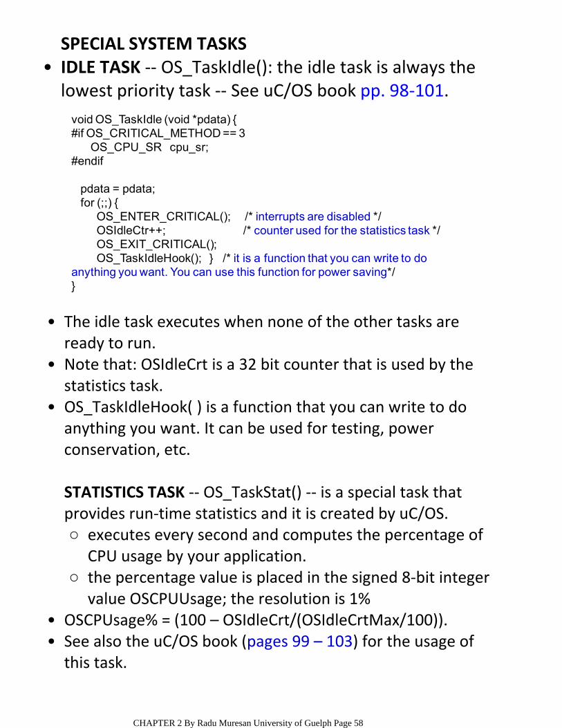
SPECIAL SYSTEM TASKSIDLE TASK ‐‐ OS_TaskIdle(): the idle task is always the lowest priority task ‐‐ See uC/OS book pp. 98‐101.
•
void OS_TaskIdle (void *pdata) {#if OS_CRITICAL_METHOD == 3
OS_CPU_SR cpu_sr;#endif
pdata = pdata;for (;;) {
OS_ENTER_CRITICAL(); /* interrupts are disabled */OSIdleCtr++; /* counter used for the statistics task */OS_EXIT_CRITICAL();OS_TaskIdleHook(); } /* it is a function that you can write to do
anything you want. You can use this function for power saving*/}
The idle task executes when none of the other tasks are ready to run.
•
Note that: OSIdleCrt is a 32 bit counter that is used by the statistics task.
•
OS_TaskIdleHook( ) is a function that you can write to do anything you want. It can be used for testing, power conservation, etc.
•
executes every second and computes the percentage of CPU usage by your application.
○
the percentage value is placed in the signed 8‐bit integer value OSCPUUsage; the resolution is 1%
○
STATISTICS TASK ‐‐ OS_TaskStat() ‐‐ is a special task that provides run‐time statistics and it is created by uC/OS.
OSCPUsage% = (100 – OSIdleCrt/(OSIdleCrtMax/100)).•See also the uC/OS book (pages 99 – 103) for the usage of this task.
•
CHAPTER 2 By Radu Muresan University of Guelph Page 58
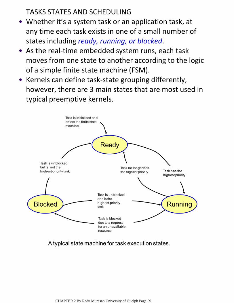
TASKS STATES AND SCHEDULINGWhether it’s a system task or an application task, at any time each task exists in one of a small number of states including ready, running, or blocked.
•
As the real‐time embedded system runs, each task moves from one state to another according to the logic of a simple finite state machine (FSM).
•
Kernels can define task‐state grouping differently, however, there are 3 main states that are most used in typical preemptive kernels.
•
Ready
Blocked Running
Task no longer hasthe highest priority. Task has the
highest priority.
Task is unblockedand is thehighest-prioritytask
Task is blockeddue to a requestfor an unavailableresource.
Task is unblockedbut is not thehighest-priority task
Task is initialized and enters the finite state machine.
A typical state machine for task execution states.
CHAPTER 2 By Radu Muresan University of Guelph Page 59
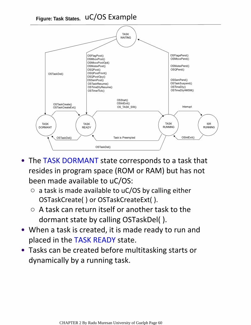
Figure: Task States.
OSTaskDel()
OSFlagPost()OSMboxPost()OSMboxPostOpt()OSMutexPost()OSQPost()OSQPostFront()OSQPostOpy()OSSemPost()OSTaskResume()OSTimeDlyResume()OSTimerTick()
OSTaskCreate()OSTaskCreateExt()
OSStart()OSIntExit()OS_TASK_SW()
OSFlagePend()OSMboxPend()
OSMutexPend()OSQPend()
OSSemPend()OSTaskSuspend()OSTimeDly()OSTimeDlyHMSM()
Interrupt
OSTaskDel() Task is Preempted OSIntExit()
OSTaskDel()
TASKDORMANT
TASKREADY
TASKRUNNING
ISRRUNNING
TASKWAITING
a task is made available to uC/OS by calling either OSTaskCreate( ) or OSTaskCreateExt( ).
○
A task can return itself or another task to the dormant state by calling OSTaskDel( ).
○
The TASK DORMANT state corresponds to a task that resides in program space (ROM or RAM) but has not been made available to uC/OS:
•
When a task is created, it is made ready to run and placed in the TASK READY state.
•
Tasks can be created before multitasking starts or dynamically by a running task.
•
uC/OS Example
CHAPTER 2 By Radu Muresan University of Guelph Page 60
If multitasking has started and a task created by another task has a higher priority than its creator, the created task is given control of the CPU immediately.
•
OSStart() must only be called once during startup and the highest priority task is placed in the TASK RUNNINGstate.
•
Only one task can be running at any given time ‐‐ a ready task does not run until all higher priority tasks are either placed in the TASK WAITING state or are deleted.
•
This task would be placed in the TASK WAITING state until the time specified in the call expires.
○
Both of these functions force an immediate context switch to the next highest priority task that is ready to run.
○
The delayed task is made ready to run by OSTimeTick( ) when the desired time delay expires (pp.108).
○
The running task can delay itself for a certain amount of time by calling either OSTimeDly( ) or OSTimeDlyHMSM( ).
•
OSTimeTick( ) is an internal function to uC/OS‐II and thus, you don’t have to actually call this function from your code.
•
When all the tasks are waiting either for events or for time to expire, uC/OS executes an internal task called the idle task, OS_TaskIdle().
•
CHAPTER 2 By Radu Muresan University of Guelph Page 61
If the event did not already occur, the task that calls one of these functions is placed in the TASK WAITING state until the occurrence of the event.
○
When a task pends on an event the next highest priority task is immediately given control of the CPU. The task is made ready when the event happens or when a timeout expires.
○
The occurrence of an event can be signaled by either another task or an ISR.
○
RUNNING tasks are placed in the TASK WAITING state when calling event functions. The running task may also need to wait until an event occurs by calling either OSFlagPend(), OSSemPend(), OSMutexPend(), OSQPend(), OSMboxPend().
•
A running task can always be interrupted, unless uC/OS disables the interrupts. When interrupted the task enters the ISR RUNNING state.
•
ISRs are treated differently by the kernel. When an interrupt occurs, execution of the task is suspended, and the ISR takes control of the CPU.
•
The ISR can make one or more tasks ready to run by signalling one or more events. In this case, before returning from the ISR, uC/OS determines if the interrupted task is still the highest priority task ready to run. If the ISR makes a higher priority task ready to run, the new highest priority task is resumed; otherwise, the interrupted task is resumed.
•
CHAPTER 2 By Radu Muresan University of Guelph Page 62
BASIC TASK OPERATIONS
For example: creating and maintaining the TCB and task stacks, etc.
○
In addition to providing a task object, kernels also provide task‐management services ‐‐ task management services include actions that a kernel performs behind the scenes to support tasks:
•
creating and deleting tasks; controlling task scheduling; and obtaining task information.
○
A kernel also provides an API (Application Program Interface) that allows developers to manipulate tasks. Common operations are:
•
EXAMPLE OF TASK CREATION IN uC/OS‐II
OSTaskCreate() or OSTaskCreateExt().○
You create a task with uC/OS by passing its address and other arguments to one of two functions:
•
A task can be created prior to the start of multitasking or by another task. You must create at least one task before OSStart(). An ISR cannot create a task.
•
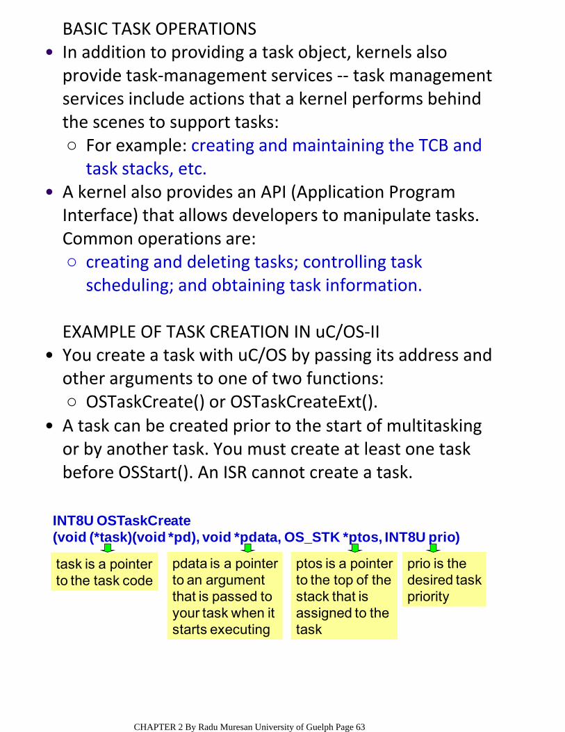
INT8U OSTaskCreate (void (*task)(void *pd), void *pdata, OS_STK *ptos, INT8U prio)
task is a pointerto the task code
pdata is a pointerto an argumentthat is passed toyour task when itstarts executing
ptos is a pointerto the top of thestack that is assigned to thetask
prio is the desired taskpriority
CHAPTER 2 By Radu Muresan University of Guelph Page 63
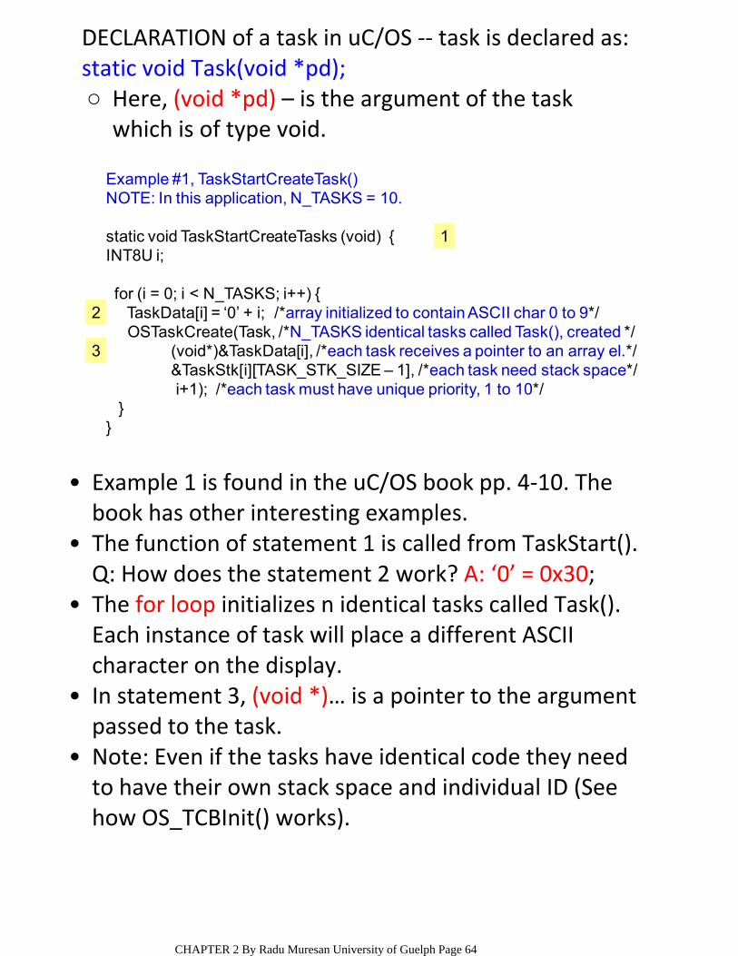
DECLARATION of a task in uC/OS ‐‐ task is declared as:
Here, (void *pd) – is the argument of the task which is of type void.
○static void Task(void *pd);
Example 1 is found in the uC/OS book pp. 4‐10. The book has other interesting examples.
•
The function of statement 1 is called from TaskStart().•Q: How does the statement 2 work? A: ‘0’ = 0x30;The for loop initializes n identical tasks called Task().•Each instance of task will place a different ASCII character on the display.In statement 3, (void *)… is a pointer to the argument passed to the task.
•
Note: Even if the tasks have identical code they need to have their own stack space and individual ID (See how OS_TCBInit() works).
•
Example #1, TaskStartCreateTask()NOTE: In this application, N_TASKS = 10.
static void TaskStartCreateTasks (void) {INT8U i;
for (i = 0; i < N_TASKS; i++) {TaskData[i] = ‘0’ + i; /*array initialized to contain ASCII char 0 to 9*/OSTaskCreate(Task, /*N_TASKS identical tasks called Task(), created */
(void*)&TaskData[i], /*each task receives a pointer to an array el.*/&TaskStk[i][TASK_STK_SIZE – 1], /*each task need stack space*/i+1); /*each task must have unique priority, 1 to 10*/
}}
1
2
3
CHAPTER 2 By Radu Muresan University of Guelph Page 64

TYPICAL TASK OPERATIONS SUPPORTING MANUAL TASK SCHEDULINGMany Kernels provide a set of API calls that allow the control of task moves.
•
Operations for task scheduling: suspend; resume; delay; restart – fresh initialized (not resumed); get priority; set priority ‐ dynamically sets a task’s priority; preemption lock – locks the scheduler; preemption unlock – unlocks the scheduler.
•
By using manual scheduling, developers can suspend and resume tasks from within an application.
•
EXAMPLE OF OPERATIONS SUPPORTING DYNAMIC SCHEDULING FROM uC/OS‐II
Changing a Task’s Priority:INT8U OSTaskChangePrio (INT8U oldprio, INT8U newprio)/*At runtime you can change the priority of any task bycalling OSTaskChangePrio()*/
Suspending a Task: INT8U OSTaskSuspend (INT8U prio)/*A suspended task can only be resumed by callingOSTaskResume() function call. Task suspension is additivewhich means that if a task is also waiting for time to expire,the suspension needs to be removed and the time needs toexpire before the task is ready to run */
CHAPTER 2 By Radu Muresan University of Guelph Page 65
INTERRUPTSInterrupts allow a microprocessor to process events when they occur, which prevents the microprocessor from continually polling an event to see if it has occurred.
•
Microprocessors allow the interrupts to be ignored and recognized through the use of two special instructions: disable interrupts (DI) and enable interrupts (EI), respectively.
•
In a real‐time environment, interrupts should be disabled as little as possible. Disabling interrupts affects interrupt latency and can cause interrupts to be missed.
•
Processors generally allow interrupts to be nested. •An interrupt is a HW mechanism used to inform the CPU that an asynchronous event has occurred.
•
When an interrupt is recognized, the CPU saves part (or all) of its context (i.e. registers) and jumps to a special subroutine, called an ISR.
•
the background for a foreground/background system; Q …Why to background? A: Because the foreground is the ISR.
○
the interrupted task for a non‐preemptive kernel, or○the highest priority task ready to run for a preemptive kernel.
○
The ISR processes the event, and, upon completion of the ISR, the program returns to:
•
ENGG4420 ‐ CHAPTER 2 ‐ LECTURE 5October‐15‐104:11 PM
CHAPTER 2 By Radu Muresan University of Guelph Page 66
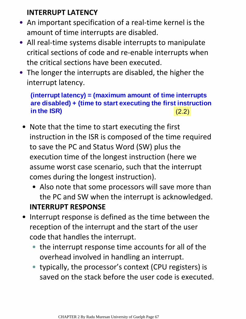
INTERRUPT LATENCYAn important specification of a real‐time kernel is the amount of time interrupts are disabled.
•
All real‐time systems disable interrupts to manipulate critical sections of code and re‐enable interrupts when the critical sections have been executed.
•
The longer the interrupts are disabled, the higher the interrupt latency.
•
(interrupt latency) = (maximum amount of time interruptsare disabled) + (time to start executing the first instruction in the ISR) (2.2)
Also note that some processors will save more than the PC and SW when the interrupt is acknowledged.
•
Note that the time to start executing the first instruction in the ISR is composed of the time required to save the PC and Status Word (SW) plus the execution time of the longest instruction (here we assume worst case scenario, such that the interrupt comes during the longest instruction).
•
INTERRUPT RESPONSE
the interrupt response time accounts for all of the overhead involved in handling an interrupt.
•
typically, the processor’s context (CPU registers) is saved on the stack before the user code is executed.
•
Interrupt response is defined as the time between the reception of the interrupt and the start of the user code that handles the interrupt.
•
CHAPTER 2 By Radu Muresan University of Guelph Page 67
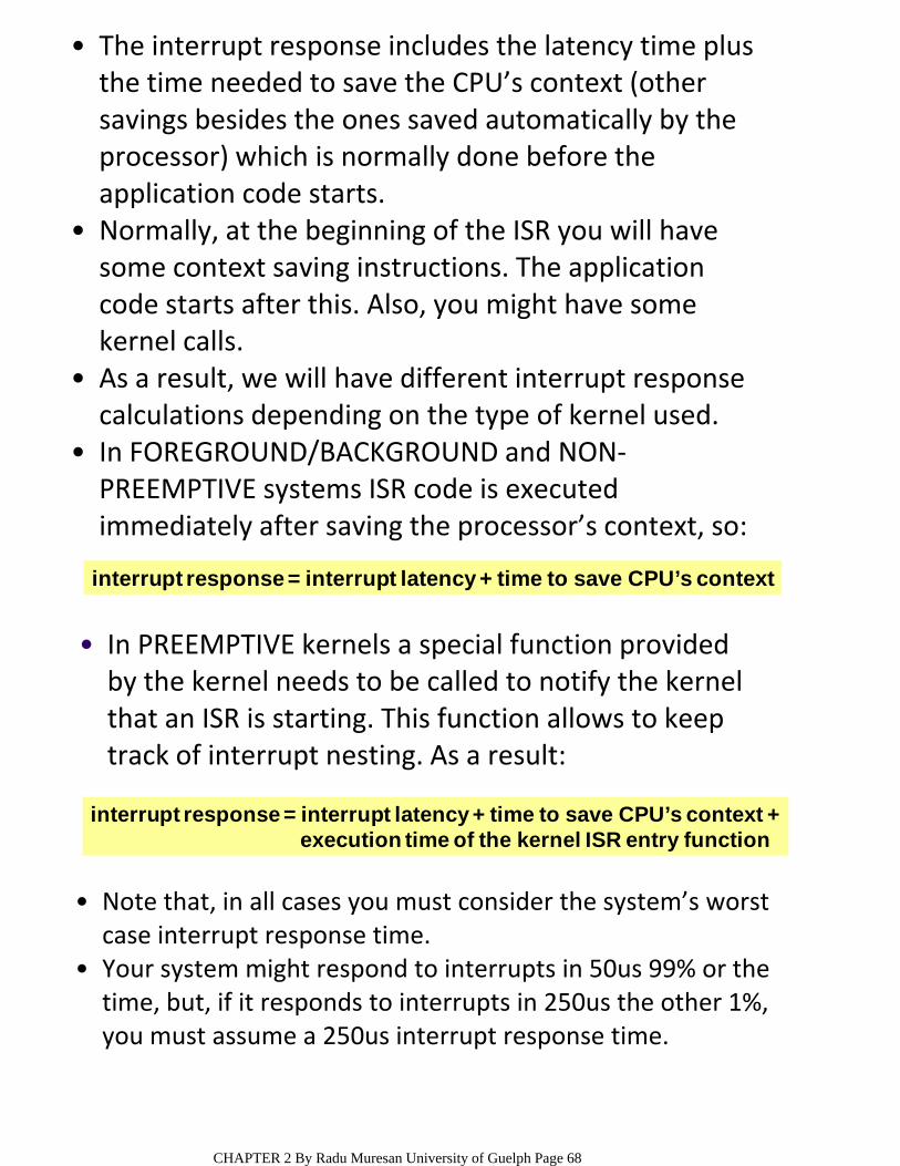
The interrupt response includes the latency time plus the time needed to save the CPU’s context (other savings besides the ones saved automatically by the processor) which is normally done before the application code starts.
•
Normally, at the beginning of the ISR you will have some context saving instructions. The application code starts after this. Also, you might have some kernel calls.
•
As a result, we will have different interrupt response calculations depending on the type of kernel used.
•
In FOREGROUND/BACKGROUND and NON‐PREEMPTIVE systems ISR code is executed immediately after saving the processor’s context, so:
•
interrupt response = interrupt latency + time to save CPU’s context
In PREEMPTIVE kernels a special function provided by the kernel needs to be called to notify the kernel that an ISR is starting. This function allows to keep track of interrupt nesting. As a result:
•
interrupt response = interrupt latency + time to save CPU’s context +execution time of the kernel ISR entry function
Note that, in all cases you must consider the system’s worst case interrupt response time.
•
Your system might respond to interrupts in 50us 99% or the time, but, if it responds to interrupts in 250us the other 1%, you must assume a 250us interrupt response time.
•
CHAPTER 2 By Radu Muresan University of Guelph Page 68
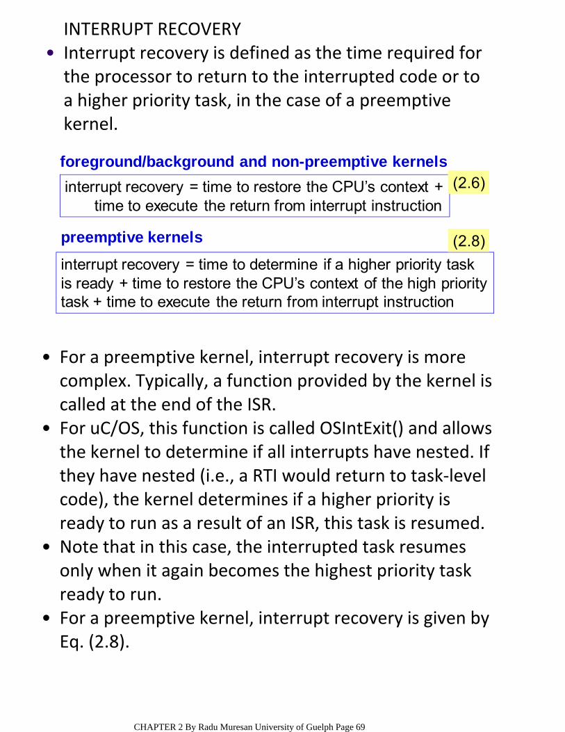
INTERRUPT RECOVERYInterrupt recovery is defined as the time required for the processor to return to the interrupted code or to a higher priority task, in the case of a preemptive kernel.
•
interrupt recovery = time to restore the CPU’s context +time to execute the return from interrupt instruction
(2.6)
interrupt recovery = time to determine if a higher priority taskis ready + time to restore the CPU’s context of the high prioritytask + time to execute the return from interrupt instruction
foreground/background and non-preemptive kernels
preemptive kernels (2.8)
For a preemptive kernel, interrupt recovery is more complex. Typically, a function provided by the kernel is called at the end of the ISR.
•
For uC/OS, this function is called OSIntExit() and allows the kernel to determine if all interrupts have nested. If they have nested (i.e., a RTI would return to task‐level code), the kernel determines if a higher priority is ready to run as a result of an ISR, this task is resumed.
•
Note that in this case, the interrupted task resumes only when it again becomes the highest priority task ready to run.
•
For a preemptive kernel, interrupt recovery is given by Eq. (2.8).
•
CHAPTER 2 By Radu Muresan University of Guelph Page 69
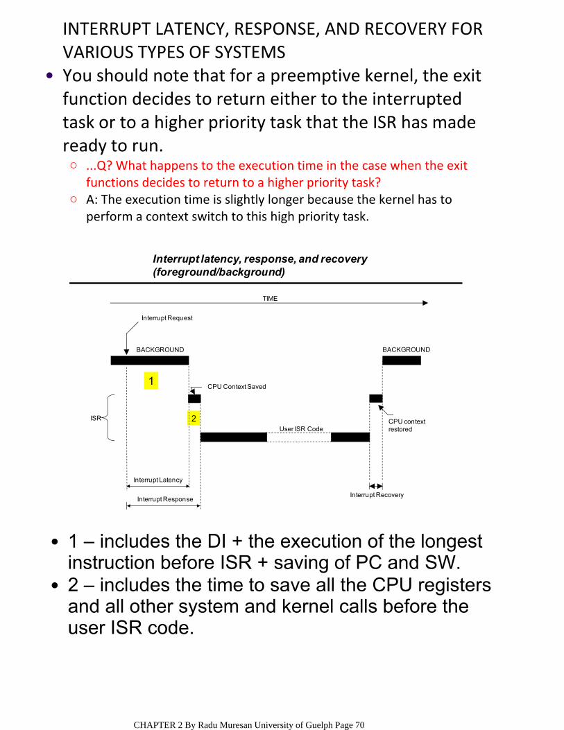
INTERRUPT LATENCY, RESPONSE, AND RECOVERY FOR VARIOUS TYPES OF SYSTEMS
...Q? What happens to the execution time in the case when the exit functions decides to return to a higher priority task?
○
A: The execution time is slightly longer because the kernel has to perform a context switch to this high priority task.
○
You should note that for a preemptive kernel, the exit function decides to return either to the interrupted task or to a higher priority task that the ISR has made ready to run.
•
1
2
TIME
Interrupt Latency
Interrupt ResponseInterrupt Recovery
Interrupt Request
BACKGROUND
CPU contextrestoredUser ISR Code
CPU Context Saved
BACKGROUND
ISR
Interrupt latency, response, and recovery(foreground/background)
1 – includes the DI + the execution of the longest instruction before ISR + saving of PC and SW.
•
2 – includes the time to save all the CPU registers and all other system and kernel calls before the user ISR code.
•
CHAPTER 2 By Radu Muresan University of Guelph Page 70
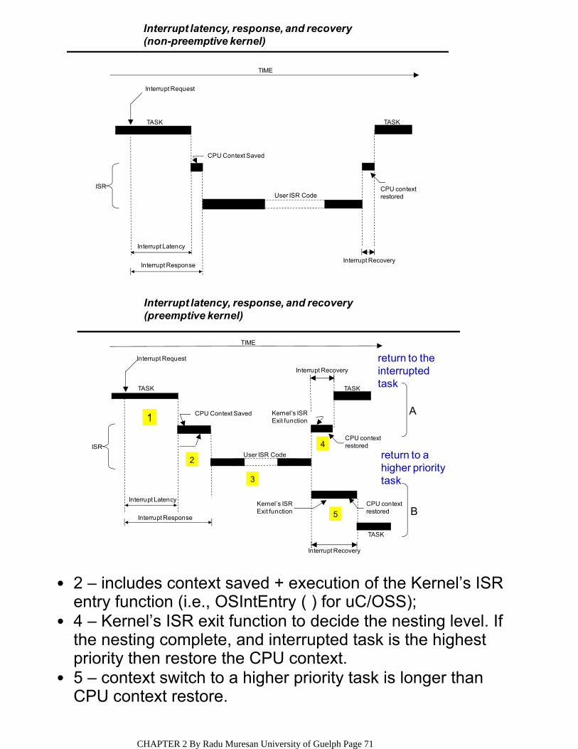
TIME
Interrupt Latency
Interrupt ResponseInterrupt Recovery
Interrupt Request
TASK
CPU contextrestoredUser ISR Code
CPU Context Saved
TASK
ISR
Interrupt latency, response, and recovery(non-preemptive kernel)
return to theinterrupted task
return to ahigher prioritytask
2
3
4
5
1
TIME
Interrupt Latency
Interrupt Response
Interrupt Recovery
Interrupt Request
CPU contextrestored
User ISR Code
CPU Context Saved
TASK
ISR
TASK
Interrupt Recovery
A
B
Kernel’s ISRExit function
CPU contextrestored
Kernel’s ISRExit function
TASK
Interrupt latency, response, and recovery(preemptive kernel)
2 – includes context saved + execution of the Kernel’s ISR entry function (i.e., OSIntEntry ( ) for uC/OSS);
•
4 – Kernel’s ISR exit function to decide the nesting level. If the nesting complete, and interrupted task is the highest priority then restore the CPU context.
•
5 – context switch to a higher priority task is longer than CPU context restore.
•
CHAPTER 2 By Radu Muresan University of Guelph Page 71
ISR PROCESSING TIMEAlthough ISRs should be as short as possible, no absolute limits on the amount of time exist for an ISR. One cannot say that an ISR must always be less than 100us, 500us, or 1 ms.
•
If the ISR code is the most important code that needs to run at any given time, it could be as long as it needs to be.
•
In most cases, however, the ISR should recognize the interrupt, obtain data or a status from the interrupting device, and signal a task to perform the actual processing.
•
You should also consider whether the overhead involved in signalling a task is more than processing of the interrupt. Signalling a task from an ISR (i.e., through a semaphore, a mailbox, or a queue) requires some processing time.
•
If processing your interrupt requires less than the time required to signal a task, you should consider processing the interrupt in the task itself and possibly enabling interrupts to allow higher priority interrupts to be recognized and serviced.
•
CHAPTER 2 By Radu Muresan University of Guelph Page 72

INTERRUPTS UNDER uC/OSS
Your ISR:Save all CPU registers;Call OSIntEnter() or, increment OSIntNesting directly;if (OSIntNesting == 1) {
OSTCBCur -> OSTCBStkPtr = SP;}Clear interrupting device;Re-enable interrupts (optional);Execute user code to service ISR;Call OSIntExit();Restore all CPU registers;Execute a return from interrupt instruction;
(1)(2)(3)(4)
(5)(6)(7)(8)(9)(10)
uC/OS requires that an ISR be written in assembly language. However, if your C compiler supports in‐line assembly you can put the ISR code directly in a C source file.
•
(1) Your code should save all CPU registers unto the current stack; this time is part of the response time.
•
(2) uC/OS needs to know that you are servicing an ISR, so you need to either call OSIntEnter() or increment the global variable OSIntNesting. Incrementing OSIntNesting directly is much faster than calling OSIntEnter() and is thus the preferred way; This time is part of the response time.
•
(4) We check to see if this level is the first interrupt level, and, if it is, we immediately save the stack pointer into the current task’s OS_TCB.
•
(5) you must clear the interrupt source because you stand the chance or re‐entering the ISR if you decide to re‐enable interrupts.
•
(8) the conclusion of the ISR is marked by calling OSIntExit(), which decrements the interrupt nesting counter. When the nesting counter reaches to 0, all nested interrupts are complete, and uC/OS needs to determine whether a higher priority task has been awakened by the ISR (or any other nested ISR). If a higher priority task is ready to run, uC/OS returns to the higher priority task rather than to the interrupted task.
•
(9) if the interrupted task is still the most important task to run, OSIntExit() returns to the ISR.
•
NOTE: uC/OS returns to the interrupted task if scheduling has been disabled. •Q: What sections within the ISR are part of the latency time, response time, and recovery time?A: Latency: none; Response: 1, 2, 3, 4, 5, and 6; Recovery: 8, 9, and 10.
CHAPTER 2 By Radu Muresan University of Guelph Page 73
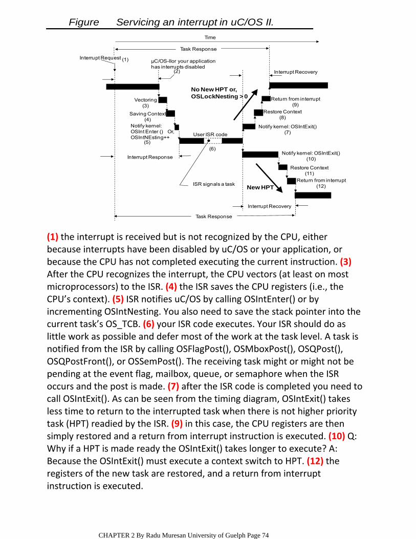
Task Response
Interrupt Recovery
New HPT
Interrupt Response
No New HPT or,OSLockNesting > 0
μC/OS-IIor your applicationhas interrupts disabled
(2)
User ISR code
(6)
Vectoring(3)
Saving Context(4)
Notify kernel:OSInt Enter () Or,OSIntNEsting++
(5)
Interrupt Request (1)
Task Response
Interrupt Recovery
Return from interrupt(9)
Restore Context(8)
Notify kernel: OSIntExit()(7)
Notify kernel: OSIntExit()(10)
Restore Context(11)
Return from interrupt(12)ISR signals a task
Time
Figure Servicing an interrupt in uC/OS II.
(1) the interrupt is received but is not recognized by the CPU, either because interrupts have been disabled by uC/OS or your application, or because the CPU has not completed executing the current instruction. (3)After the CPU recognizes the interrupt, the CPU vectors (at least on most microprocessors) to the ISR. (4) the ISR saves the CPU registers (i.e., the CPU’s context). (5) ISR notifies uC/OS by calling OSIntEnter() or by incrementing OSIntNesting. You also need to save the stack pointer into the current task’s OS_TCB. (6) your ISR code executes. Your ISR should do as little work as possible and defer most of the work at the task level. A task is notified from the ISR by calling OSFlagPost(), OSMboxPost(), OSQPost(), OSQPostFront(), or OSSemPost(). The receiving task might or might not be pending at the event flag, mailbox, queue, or semaphore when the ISR occurs and the post is made. (7) after the ISR code is completed you need to call OSIntExit(). As can be seen from the timing diagram, OSIntExit() takes less time to return to the interrupted task when there is not higher priority task (HPT) readied by the ISR. (9) in this case, the CPU registers are then simply restored and a return from interrupt instruction is executed. (10) Q: Why if a HPT is made ready the OSIntExit() takes longer to execute? A: Because the OSIntExit() must execute a context switch to HPT. (12) the registers of the new task are restored, and a return from interrupt instruction is executed.
CHAPTER 2 By Radu Muresan University of Guelph Page 74
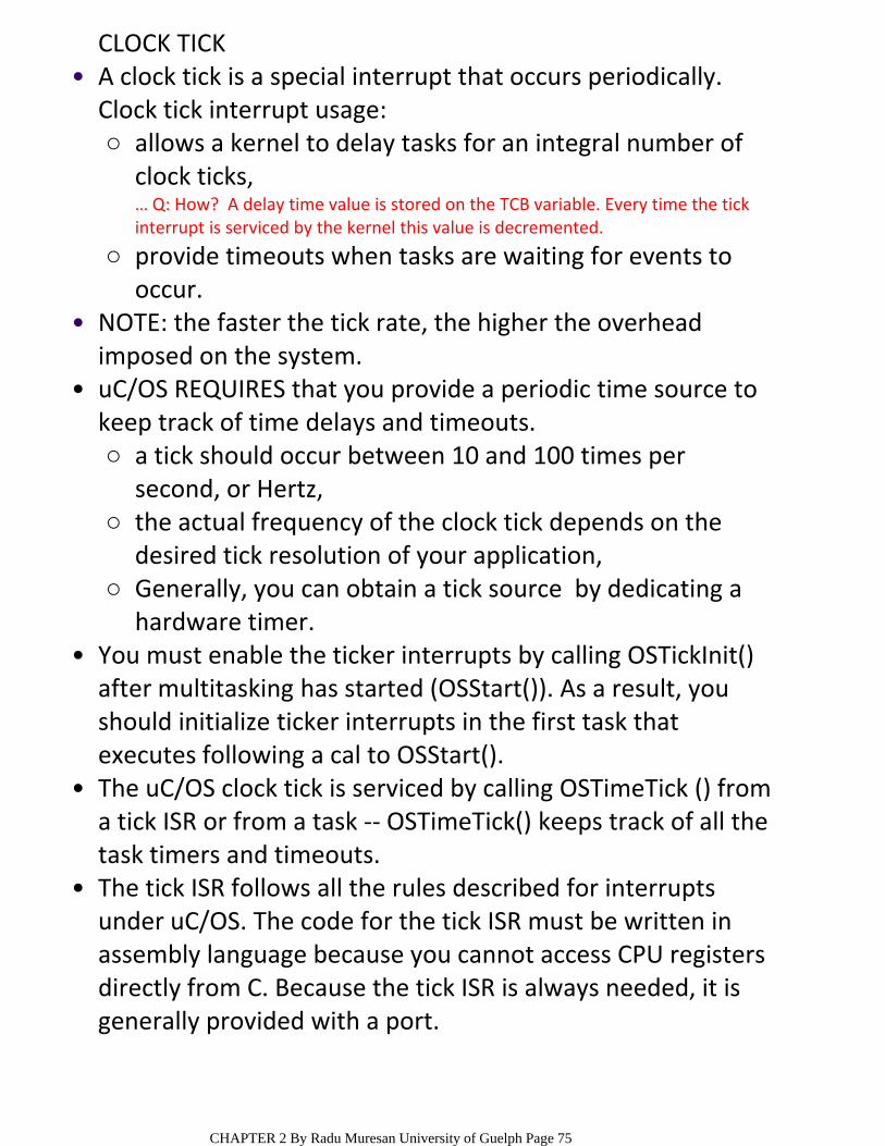
CLOCK TICK
allows a kernel to delay tasks for an integral number of clock ticks,
○
… Q: How? A delay time value is stored on the TCB variable. Every time the tick interrupt is serviced by the kernel this value is decremented.
provide timeouts when tasks are waiting for events to occur.
○
A clock tick is a special interrupt that occurs periodically. Clock tick interrupt usage:
•
NOTE: the faster the tick rate, the higher the overhead imposed on the system.
•
a tick should occur between 10 and 100 times per second, or Hertz,
○
the actual frequency of the clock tick depends on the desired tick resolution of your application,
○
Generally, you can obtain a tick source by dedicating a hardware timer.
○
uC/OS REQUIRES that you provide a periodic time source to keep track of time delays and timeouts.
•
You must enable the ticker interrupts by calling OSTickInit() after multitasking has started (OSStart()). As a result, you should initialize ticker interrupts in the first task that executes following a cal to OSStart().
•
The uC/OS clock tick is serviced by calling OSTimeTick () from a tick ISR or from a task ‐‐ OSTimeTick() keeps track of all the task timers and timeouts.
•
The tick ISR follows all the rules described for interrupts under uC/OS. The code for the tick ISR must be written in assembly language because you cannot access CPU registers directly from C. Because the tick ISR is always needed, it is generally provided with a port.
•
CHAPTER 2 By Radu Muresan University of Guelph Page 75
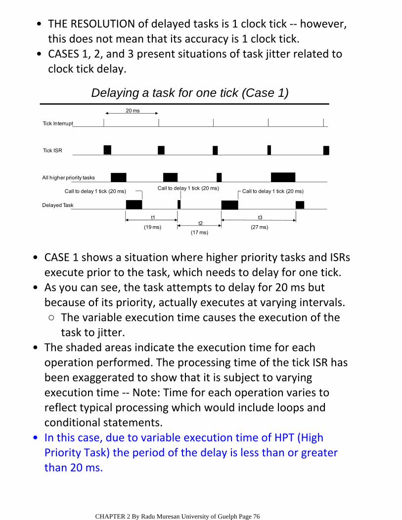
20 ms
t1t2
t3
(27 ms)(17 ms)
(19 ms)
Delayed Task
Call to delay 1 tick (20 ms)Call to delay 1 tick (20 ms)
Call to delay 1 tick (20 ms)
All higher priority tasks
Tick ISR
Tick Interrupt
Delaying a task for one tick (Case 1)
CASE 1 shows a situation where higher priority tasks and ISRs execute prior to the task, which needs to delay for one tick.
•
The variable execution time causes the execution of the task to jitter.
○
As you can see, the task attempts to delay for 20 ms but because of its priority, actually executes at varying intervals.
•
The shaded areas indicate the execution time for each operation performed. The processing time of the tick ISR has been exaggerated to show that it is subject to varying execution time ‐‐ Note: Time for each operation varies to reflect typical processing which would include loops and conditional statements.
•
In this case, due to variable execution time of HPT (High Priority Task) the period of the delay is less than or greater than 20 ms.
•
THE RESOLUTION of delayed tasks is 1 clock tick ‐‐ however, this does not mean that its accuracy is 1 clock tick.
•
CASES 1, 2, and 3 present situations of task jitter related to clock tick delay.
•
CHAPTER 2 By Radu Muresan University of Guelph Page 76

20 ms
t1t2
t3
(27 ms)(19 ms)(6 ms)
Delayed Task
Call to delay 1 tick (20 ms)Call to delay 1 tick (20 ms) Call to delay 1 tick (20 ms)
All higher priority tasks
Tick ISR
Tick Interrupt
Delaying a task for one tick (Case 2)
CASE 2 shows a situation where the execution times of all higher priority tasks and ISRs are slightly less than one tick.
•
If the task delays itself just before a clock tick, the task executes again almost immediately.
•
In other words, if you need to delay a task for at least 5 ticks, you must specify 6 ticks.
○
As a result of this, if you need to delay a task at least one clock tick, you must specify one extra tick.
•
CHAPTER 2 By Radu Muresan University of Guelph Page 77
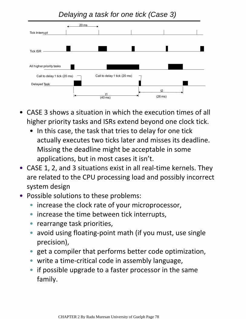
20 ms
t1t2
(26 ms)(40 ms)
Delayed Task
Call to delay 1 tick (20 ms) Call to delay 1 tick (20 ms)
All higher priority tasks
Tick ISR
Tick Interrupt
Delaying a task for one tick (Case 3)
In this case, the task that tries to delay for one tick actually executes two ticks later and misses its deadline. Missing the deadline might be acceptable in some applications, but in most cases it isn’t.
•
CASE 3 shows a situation in which the execution times of all higher priority tasks and ISRs extend beyond one clock tick.
•
CASE 1, 2, and 3 situations exist in all real‐time kernels. They are related to the CPU processing load and possibly incorrect system design
•
increase the clock rate of your microprocessor,•increase the time between tick interrupts,•rearrange task priorities,•avoid using floating‐point math (if you must, use single precision),
•
get a compiler that performs better code optimization,•write a time‐critical code in assembly language,•if possible upgrade to a faster processor in the same family.
•
Possible solutions to these problems:•
CHAPTER 2 By Radu Muresan University of Guelph Page 78
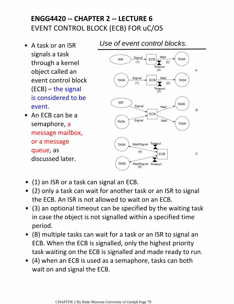
ISR
ISR
TASK
TASK
TASK
TASK
TASKTASK
TASK
TASK
ECB
ECB
ECB
Signal
Signal
Signal
Signal Wait
Wait
Wait
Wait
Wait/Signal
Wait/Signal
Timeout
Timeout
Timeout
Timeout
(4)
(4)
(2)
(2)(1)
(1)
(3)
(3)
A
B
C
Use of event control blocks.
ECB
ENGG4420 ‐‐ CHAPTER 2 ‐‐ LECTURE 6EVENT CONTROL BLOCK (ECB) FOR uC/OS
A task or an ISR signals a task through a kernel object called an event control block (ECB) – the signal is considered to be event.
•
An ECB can be a semaphore, a message mailbox, or a message queue, as discussed later.
•
(1) an ISR or a task can signal an ECB.•(2) only a task can wait for another task or an ISR to signal the ECB. An ISR is not allowed to wait on an ECB.
•
(3) an optional timeout can be specified by the waiting task in case the object is not signalled within a specified time period.
•
(B) multiple tasks can wait for a task or an ISR to signal an ECB. When the ECB is signalled, only the highest priority task waiting on the ECB is signalled and made ready to run.
•
(4) when an ECB is used as a semaphore, tasks can both wait on and signal the ECB.
•
CHAPTER 2 By Radu Muresan University of Guelph Page 79

ECB is used as a building block to implement services, such as semaphore management, mutual exclusion semaphores, message mailbox management, and message queue management.
•
uC/OS maintains the state of an ECB in a data structure called OS_EVENT.
•
typedef struct {INT8U OSEventType; /* Event type */INT8U OSEventGrp; /* Group for wait list */INT16U OSEventCnt; /* Count (when event is a semaphore)*/void *OSEventPtr; /* Ptr to message or queue structure */INT8U OSEventTbl[OS_EVENT_TBL_SIZE]; /*wait list for event
to occur */} OS_EVENT;
NOTE: A dot in front of a variable name indicates that the variable is part of a data structure.
•
.OSEventType contains the type associated with the ECB and can have the following vaues: OS_EVENT_TYPE_SEM, OS_EVENT_TYPE_MUTEX, OS_EVENT_TYPE_MBOX, or OS‐EVENT_TYPE_Q. This field is used to make sure that you are accessing the proper object when you perform operations on these objects through the uC/OS service calls.
•
CHAPTER 2 By Radu Muresan University of Guelph Page 80
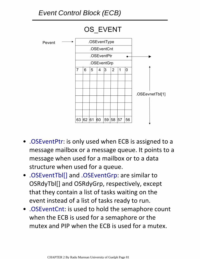
7 6 5 4 3 2 1 0
63 62 61 60 59 58 57 56
.OSEventType
.OSEventCnt
.OSEventPtr
.OSEventGrp
OS_EVENT
Pevent
.OSEevnetTbl[1]
Event Control Block (ECB)
.OSEventPtr: is only used when ECB is assigned to a message mailbox or a message queue. It points to a message when used for a mailbox or to a data structure when used for a queue.
•
.OSEventTbl[] and .OSEventGrp: are similar to OSRdyTbl[] and OSRdyGrp, respectively, except that they contain a list of tasks waiting on the event instead of a list of tasks ready to run.
•
.OSEventCnt: is used to hold the semaphore count when the ECB is used for a semaphore or the mutex and PIP when the ECB is used for a mutex.
•
CHAPTER 2 By Radu Muresan University of Guelph Page 81
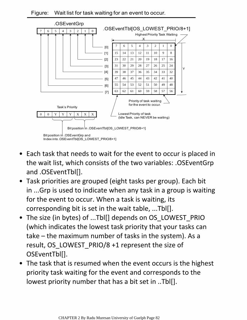
5657585960616263
4849505152535455
4041424344454647
3233343536373839
2425262728293031
1617181920212223
89101112131415
01234567
01234567
[0]
[1]
[2]
[3]
[4]
[5]
[6]
[7]
XXXYYY00
Y
Bit position in .OSEventGrp andIndex into .OSEventTbl[OS_LOWEST_PRIO/8+1]
Bit position in .OSEventTbl[OS_LOWEST_PRIO/8+1]
.OSEventTbl[OS_LOWEST_PRIO/8+1]
Priority of task waitingfor the event to occur.
Lowest Priority of task (Idle Task, can NEVER be waiting)
X
Highest Priority Task Waiting
Task’s Priority
.OSEventGrp
Figure: Wait list for task waiting for an event to occur.
Each task that needs to wait for the event to occur is placed in the wait list, which consists of the two variables: .OSEventGrp and .OSEventTbl[].
•
Task priorities are grouped (eight tasks per group). Each bit in ...Grp is used to indicate when any task in a group is waiting for the event to occur. When a task is waiting, its corresponding bit is set in the wait table, ...Tbl[].
•
The size (in bytes) of ...Tbl[] depends on OS_LOWEST_PRIO (which indicates the lowest task priority that your tasks can take – the maximum number of tasks in the system). As a result, OS_LOWEST_PRIO/8 +1 represent the size of OSEventTbl[].
•
The task that is resumed when the event occurs is the highest priority task waiting for the event and corresponds to the lowest priority number that has a bit set in ..Tbl[].
•
CHAPTER 2 By Radu Muresan University of Guelph Page 82
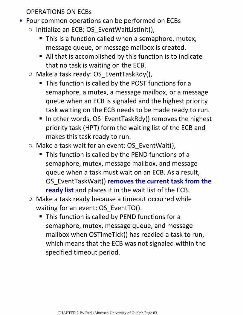
OPERATIONS ON ECBs
This is a function called when a semaphore, mutex, message queue, or message mailbox is created.
All that is accomplished by this function is to indicate that no task is waiting on the ECB.
Initialize an ECB: OS_EventWaitListInit(),○
This function is called by the POST functions for a semaphore, a mutex, a message mailbox, or a message queue when an ECB is signaled and the highest priority task waiting on the ECB needs to be made ready to run.
In other words, OS_EventTaskRdy() removes the highest priority task (HPT) form the waiting list of the ECB and makes this task ready to run.
Make a task ready: OS_EventTaskRdy(),○
This function is called by the PEND functions of a semaphore, mutex, message mailbox, and message queue when a task must wait on an ECB. As a result, OS_EventTaskWait() removes the current task from the ready list and places it in the wait list of the ECB.
Make a task wait for an event: OS_EventWait(),○
This function is called by PEND functions for a semaphore, mutex, message queue, and message mailbox when OSTimeTick() has readied a task to run, which means that the ECB was not signaled within the specified timeout period.
Make a task ready because a timeout occurred while waiting for an event: OS_EventTO().
○
Four common operations can be performed on ECBs•
CHAPTER 2 By Radu Muresan University of Guelph Page 83
MEMORY REQUIREMENTS FOR REAL‐TIME SYSTEMS
A minimal kernel for an 8‐bit CPU that provides only scheduling, context switching, semaphore management, delays, and timeouts is 1K to 3K bytes.
○The size of a kernel is from 1K to 100K bytes.•
Total code space = application space + kernel space.•
application code requirements + data space needed by the kernel itself + SUM (task staks + MAX(ISR nesting)).
○
Total RAM if the kernel does not support a separate interrupt stack is:
•
application + data space needed by the kernel + SUM(task stacks) + MAX(ISR nesting).
○If the kernel supports a separate stack for interrupts is:•
CHAPTER 2 By Radu Muresan University of Guelph Page 84
SYNCHRONIZATION, COMMUNICATION, AND CONCURRENCYTOPICS COVERED IN THIS SECTION ARE:Synchronization and communication1.Objects used for synchronization, communication and signaling (semaphores, mutexes, mailboxes, message queues, etc.)
2.
Pattern designs for inter‐task synchronization and communication
3.
Common design problems (deadlocks, priority inversion)
4.
SYNCHRONIZATIONReal time system applications use multiple concurrent tasks to maximize efficiency ‐‐ coordinating these activities requires inter‐task synchronization and communication.
•
resource synchronization ‐‐ determines whether access to a shared resource is safe, and, if not, when it will be safe.
○
activity synchronization ‐‐ determines whether the execution of a multithreaded program has reached a certain state, and, if it hasn’t, how to wait for and be notified when this state is reached.
○
Synchronization is classified in two categories:•
CHAPTER 2 By Radu Muresan University of Guelph Page 85
RESOURCE SYNCHRONIZATION
Shared Resource: is a resource that can be used by more than one task. Each task should gain exclusive access to the shared resource to prevent data corruption. This process is called mutual exclusion.
○
Access by multiple tasks must be synchronized to maintain the integrity of a shared resource.
•
Resource synchronization is closely associated with critical sections and mutual exclusions.
•
Mutual exclusion is a provision by which only one task at a time can access a shared resource.
•
Critical section: a critical section of code, also called a critical region, is code that needs to be treated indivisibly. After the section of code starts executing, it must not be interrupted. To ensure that execution is not interrupted, interrupts are typically disabled before the critical code is executed and enabled when the critical code is finished.
○
A critical section is the section of code from which the shared resource is accessed.
•
CHAPTER 2 By Radu Muresan University of Guelph Page 86

EXAMPLE OF TWO TASKS TRYING TO ACCESS SHARED MEMORYProblem arises if access to the shared memory is not•exclusive, and multiple tasks can simultaneously access it ‐‐ As an example, consider two tasks trying to access shared memory.
Sensor Task
Display Task
Memory
Inputs fromI/O Devices
Writes to Memory Reads from Memory
Outputs toI/O Devices
One task (the sensor task) periodically receives data from a sensor and writes the data to shared memory.
•
Meanwhile, a second task (display task) reads the data from the memory and displays it.
•
Erroneous data interpretation can take place. ...Q1? ... Q2?•Q1: How can we get erroneous data in this scenario?•A: One task (the sensor task) periodically receives data from a sensor and writes the data to the shared memory. If the sensor task has not completely written the data to the shared memory area before the display task tries to display the data, the display would contain a mixture of data extracted at different times, leading to erroneous data interpretation.
Q2: Identify the critical sections of code in this example.•A: The section of code in the sensor task that writes input data to the shared memory is a critical section of the sensor task. The section of code in the display task that reads data from the shared memory is a critical section of the display task. These two critical sections are called competing critical sections because they access the same shared resource.
CHAPTER 2 By Radu Muresan University of Guelph Page 87
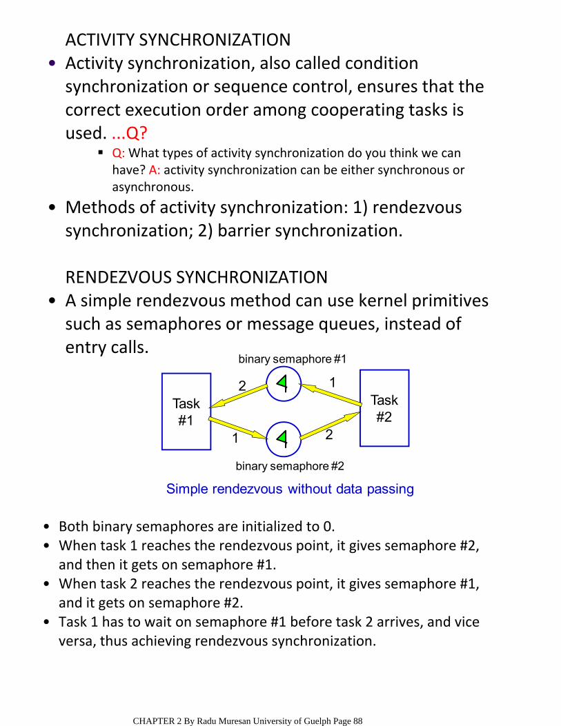
ACTIVITY SYNCHRONIZATION
Q: What types of activity synchronization do you think we can have? A: activity synchronization can be either synchronous or asynchronous.
Activity synchronization, also called condition synchronization or sequence control, ensures that the correct execution order among cooperating tasks is used. ...Q?
•
Methods of activity synchronization: 1) rendezvous synchronization; 2) barrier synchronization.
•
RENDEZVOUS SYNCHRONIZATIONA simple rendezvous method can use kernel primitives such as semaphores or message queues, instead of entry calls.
•
Task#1
Task#2
12
1 2
binary semaphore #1
binary semaphore #2
Simple rendezvous without data passing
Both binary semaphores are initialized to 0. •When task 1 reaches the rendezvous point, it gives semaphore #2, and then it gets on semaphore #1.
•
When task 2 reaches the rendezvous point, it gives semaphore #1, and it gets on semaphore #2.
•
Task 1 has to wait on semaphore #1 before task 2 arrives, and vice versa, thus achieving rendezvous synchronization.
•
CHAPTER 2 By Radu Muresan University of Guelph Page 88
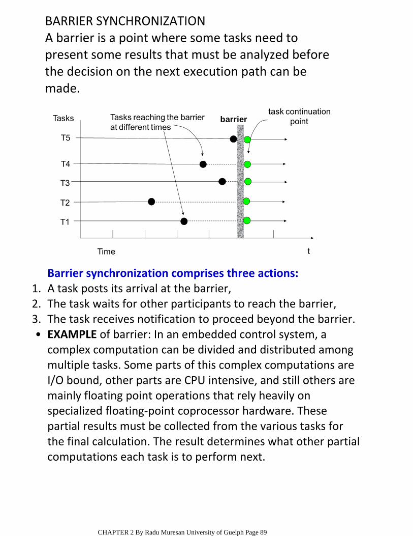
BARRIER SYNCHRONIZATIONA barrier is a point where some tasks need to present some results that must be analyzed before the decision on the next execution path can be made.
Time t
task continuationpointTasks
T5
T4
T3
T2
T1
barrierTasks reaching the barrierat different times
Barrier synchronization comprises three actions:A task posts its arrival at the barrier,1.The task waits for other participants to reach the barrier,2.The task receives notification to proceed beyond the barrier.3.EXAMPLE of barrier: In an embedded control system, a complex computation can be divided and distributed among multiple tasks. Some parts of this complex computations are I/O bound, other parts are CPU intensive, and still others are mainly floating point operations that rely heavily on specialized floating‐point coprocessor hardware. These partial results must be collected from the various tasks for the final calculation. The result determines what other partial computations each task is to perform next.
•
CHAPTER 2 By Radu Muresan University of Guelph Page 89
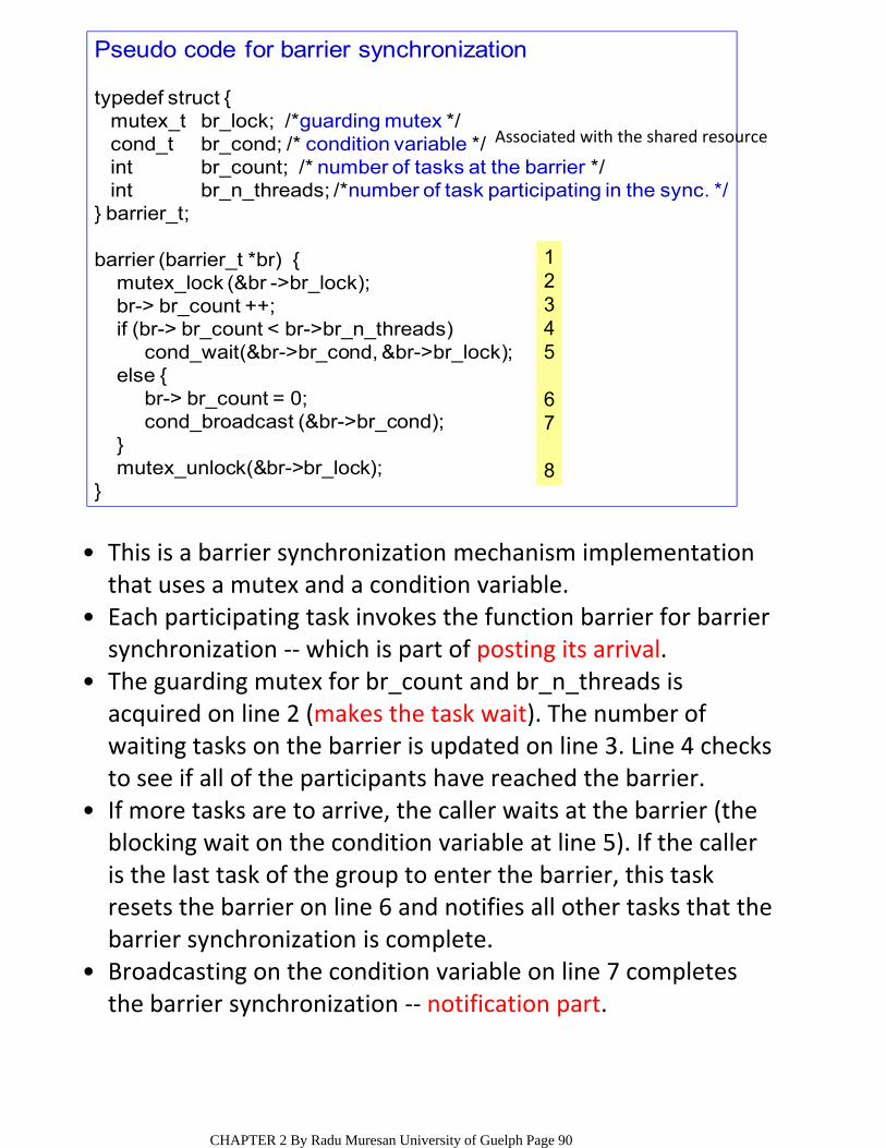
Pseudo code for barrier synchronization
typedef struct {mutex_t br_lock; /*guarding mutex */cond_t br_cond; /* condition variable */int br_count; /* number of tasks at the barrier */int br_n_threads; /*number of task participating in the sync. */
} barrier_t;
barrier (barrier_t *br) {mutex_lock (&br ->br_lock);br-> br_count ++;if (br-> br_count < br->br_n_threads)
cond_wait(&br->br_cond, &br->br_lock);else {
br-> br_count = 0;cond_broadcast (&br->br_cond);
}mutex_unlock(&br->br_lock);
}
This is a barrier synchronization mechanism implementation that uses a mutex and a condition variable.
•
Each participating task invokes the function barrier for barrier synchronization ‐‐ which is part of posting its arrival.
•
The guarding mutex for br_count and br_n_threads is acquired on line 2 (makes the task wait). The number of waiting tasks on the barrier is updated on line 3. Line 4 checks to see if all of the participants have reached the barrier.
•
If more tasks are to arrive, the caller waits at the barrier (the blocking wait on the condition variable at line 5). If the caller is the last task of the group to enter the barrier, this task resets the barrier on line 6 and notifies all other tasks that the barrier synchronization is complete.
•
Broadcasting on the condition variable on line 7 completes the barrier synchronization ‐‐ notification part.
•
12345
67
8
Associated with the shared resource
CHAPTER 2 By Radu Muresan University of Guelph Page 90
COMMUNICATIONTasks in a multitasking environment communicate with one another so they can pass information to each other and coordinate their activity.
•
signal‐centric ‐‐ all necessary information is conveyed within the event signal itself.
○
data‐centric ‐‐ the information is carried within the transferred data.
○
or both ‐‐ data transfer accompanies event notification.
○
Types of communications are:•
COMMUNICATION PURPOSESTransferring data from one task to another,•signaling the occurrences of events between tasks,•allowing one task to control the execution of other tasks,
•
synchronizing activities, and•implementing custom synchronization protocols for resource sharing
•
The main kernel objects used for task communications are message mailboxes and message queues
CHAPTER 2 By Radu Muresan University of Guelph Page 91
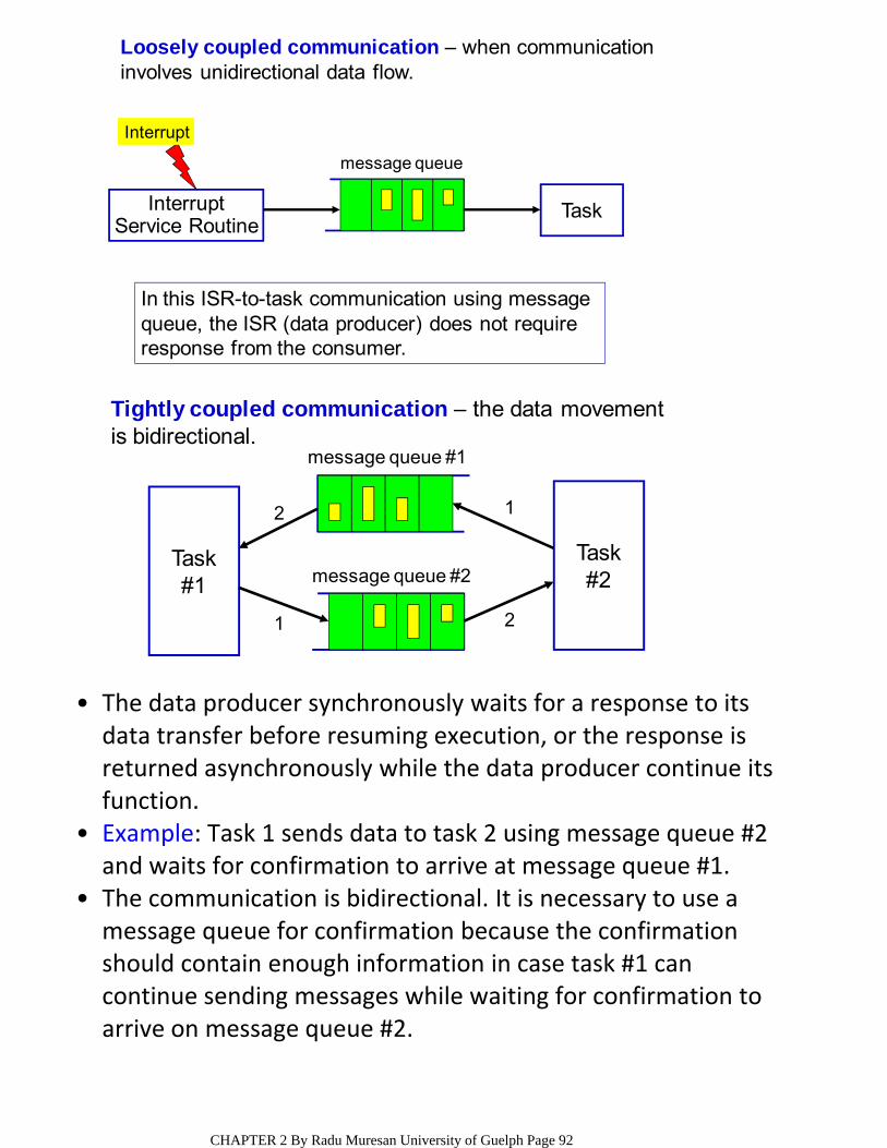
InterruptService Routine
Task
Interrupt
message queue
Loosely coupled communication – when communicationinvolves unidirectional data flow.
In this ISR-to-task communication using message queue, the ISR (data producer) does not require response from the consumer.
Task#2
Task#1 message queue #2
message queue #1
1 2
12
Tightly coupled communication – the data movementis bidirectional.
The data producer synchronously waits for a response to its data transfer before resuming execution, or the response is returned asynchronously while the data producer continue its function.
•
Example: Task 1 sends data to task 2 using message queue #2 and waits for confirmation to arrive at message queue #1.
•
The communication is bidirectional. It is necessary to use a message queue for confirmation because the confirmation should contain enough information in case task #1 can continue sending messages while waiting for confirmation to arrive on message queue #2.
•
CHAPTER 2 By Radu Muresan University of Guelph Page 92

RESOURCE SYNCHRONIZATION METHODS IN RTOSResource synchronization or mutual exclusion methods are: 1) interrupt locking (disabling system interrupts),
•
2) preemptive locking (disabling the kernel scheduler); 3) performing test‐and‐set operations; 4) using semaphores and event flags (semaphores, event flags and other kernel objects are described in the next section)DISABLING SYSTEM INTERRUPTS
Disable interrupts;Access the resource (read/write from/to variable);
Reenable interrupts;
NOTE: most of the kernels (including uC/OS) use this method
/*using uC/OS macros to disable and enable interrupts */
void Function (void){
OS_ENTER_CRITICAL();...... /*you can access shared data in here */...OS_EXIT_CRITICAL();
}
Interrupt locking (disabling system interrupts) is the method used to synchronize exclusive access to shared resources between tasks and ISRs. This process guarantees that the current task continues to execute until it voluntarily relinquishes control. As such, interrupt locking can also be used to synchronize access to shared resources between tasks. Interrupt locks, although the most powerful and the most effective synchronization method, can introduce indeterminism into the system when used indiscriminately. Therefore, the duration of interrupt locks should be short, and interrupt locks should be used only when necessary to guard a task‐level critical region from interrupt activities.
•
CHAPTER 2 By Radu Muresan University of Guelph Page 93
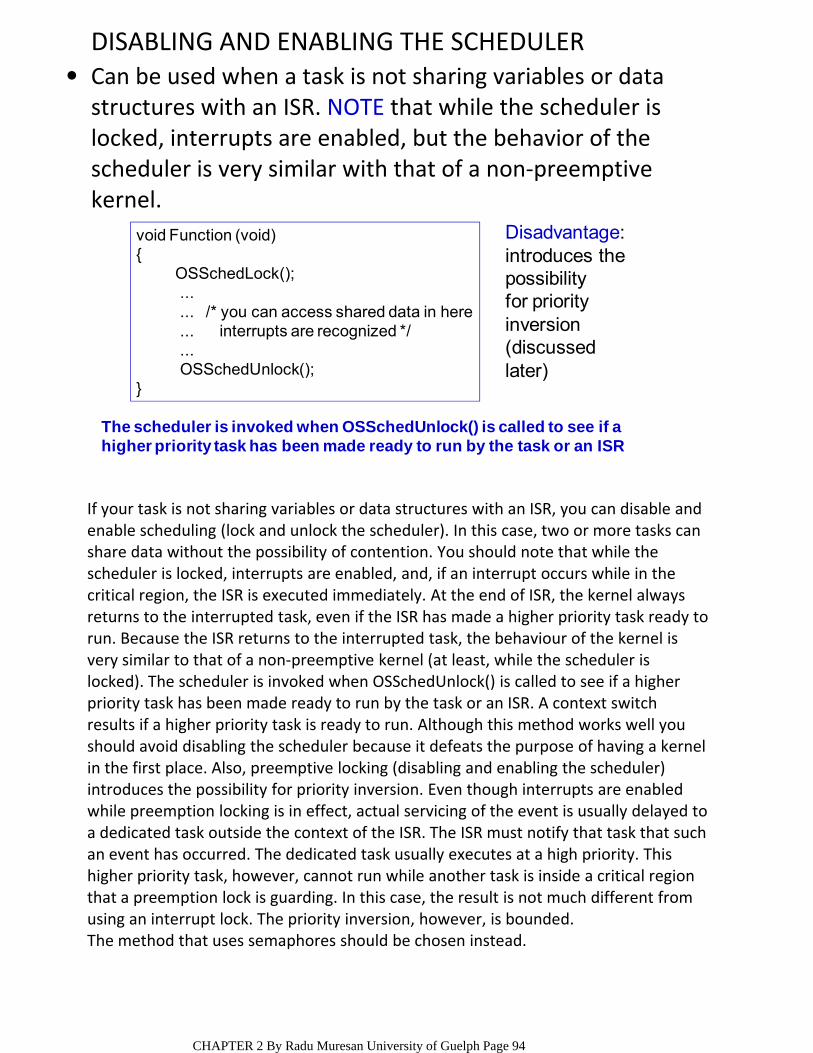
DISABLING AND ENABLING THE SCHEDULERCan be used when a task is not sharing variables or data structures with an ISR. NOTE that while the scheduler is locked, interrupts are enabled, but the behavior of the scheduler is very similar with that of a non‐preemptive kernel.
•
void Function (void){
OSSchedLock();...... /* you can access shared data in here... interrupts are recognized */...OSSchedUnlock();
}
The scheduler is invoked when OSSchedUnlock() is called to see if a higher priority task has been made ready to run by the task or an ISR
Disadvantage:introduces thepossibility for priorityinversion(discussed later)
If your task is not sharing variables or data structures with an ISR, you can disable and enable scheduling (lock and unlock the scheduler). In this case, two or more tasks can share data without the possibility of contention. You should note that while the scheduler is locked, interrupts are enabled, and, if an interrupt occurs while in the critical region, the ISR is executed immediately. At the end of ISR, the kernel always returns to the interrupted task, even if the ISR has made a higher priority task ready to run. Because the ISR returns to the interrupted task, the behaviour of the kernel is very similar to that of a non‐preemptive kernel (at least, while the scheduler is locked). The scheduler is invoked when OSSchedUnlock() is called to see if a higher priority task has been made ready to run by the task or an ISR. A context switch results if a higher priority task is ready to run. Although this method works well you should avoid disabling the scheduler because it defeats the purpose of having a kernel in the first place. Also, preemptive locking (disabling and enabling the scheduler) introduces the possibility for priority inversion. Even though interrupts are enabled while preemption locking is in effect, actual servicing of the event is usually delayed to a dedicated task outside the context of the ISR. The ISR must notify that task that such an event has occurred. The dedicated task usually executes at a high priority. This higher priority task, however, cannot run while another task is inside a critical region that a preemption lock is guarding. In this case, the result is not much different from using an interrupt lock. The priority inversion, however, is bounded. The method that uses semaphores should be chosen instead.
CHAPTER 2 By Radu Muresan University of Guelph Page 94
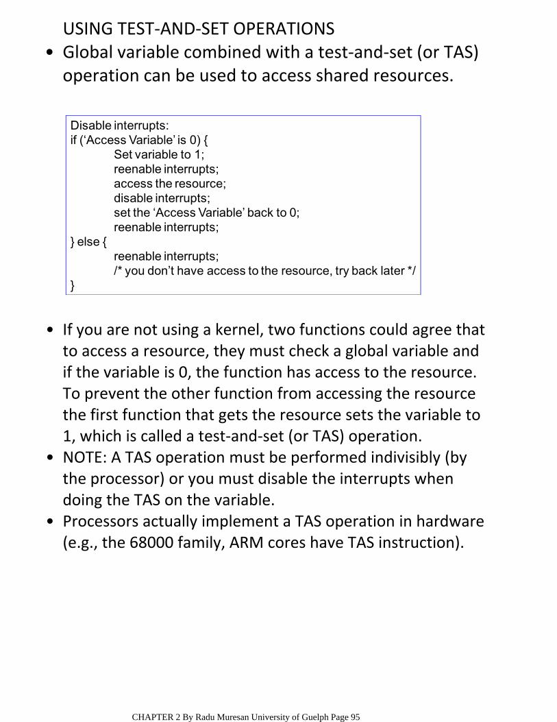
USING TEST‐AND‐SET OPERATIONSGlobal variable combined with a test‐and‐set (or TAS) operation can be used to access shared resources.
•
Disable interrupts:if (‘Access Variable’ is 0) {
Set variable to 1;reenable interrupts;access the resource;disable interrupts;set the ‘Access Variable’ back to 0;reenable interrupts;
} else {reenable interrupts;/* you don’t have access to the resource, try back later */
}
If you are not using a kernel, two functions could agree that to access a resource, they must check a global variable and if the variable is 0, the function has access to the resource. To prevent the other function from accessing the resource the first function that gets the resource sets the variable to 1, which is called a test‐and‐set (or TAS) operation.
•
NOTE: A TAS operation must be performed indivisibly (by the processor) or you must disable the interrupts when doing the TAS on the variable.
•
Processors actually implement a TAS operation in hardware (e.g., the 68000 family, ARM cores have TAS instruction).
•
CHAPTER 2 By Radu Muresan University of Guelph Page 95
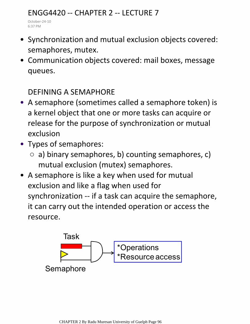
Synchronization and mutual exclusion objects covered: semaphores, mutex.
•
Communication objects covered: mail boxes, message queues.
•
DEFINING A SEMAPHOREA semaphore (sometimes called a semaphore token) is a kernel object that one or more tasks can acquire or release for the purpose of synchronization or mutual exclusion
•
a) binary semaphores, b) counting semaphores, c)mutual exclusion (mutex) semaphores.
○Types of semaphores:•
A semaphore is like a key when used for mutual exclusion and like a flag when used for synchronization ‐‐ if a task can acquire the semaphore, it can carry out the intended operation or access the resource.
•
Task
Semaphore
*Operations*Resource access
ENGG4420 ‐‐ CHAPTER 2 ‐‐ LECTURE 7October‐24‐106:37 PM
CHAPTER 2 By Radu Muresan University of Guelph Page 96
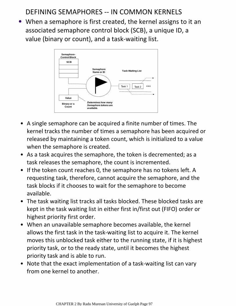
DEFINING SEMAPHORES ‐‐ IN COMMON KERNELSWhen a semaphore is first created, the kernel assigns to it an associated semaphore control block (SCB), a unique ID, a value (binary or count), and a task‐waiting list.
•
Task 1 Task 2
Value
Binary or aCount
Semaphore-Control Block
SemaphoreName or ID
Determines how manySemaphore tokens areavailable.
Task-Waiting List
SCB
A single semaphore can be acquired a finite number of times. The kernel tracks the number of times a semaphore has been acquired or released by maintaining a token count, which is initialized to a value when the semaphore is created.
•
As a task acquires the semaphore, the token is decremented; as a task releases the semaphore, the count is incremented.
•
If the token count reaches 0, the semaphore has no tokens left. A requesting task, therefore, cannot acquire the semaphore, and the task blocks if it chooses to wait for the semaphore to become available.
•
The task waiting list tracks all tasks blocked. These blocked tasks are kept in the task waiting list in either first in/first out (FIFO) order or highest priority first order.
•
When an unavailable semaphore becomes available, the kernel allows the first task in the task‐waiting list to acquire it. The kernel moves this unblocked task either to the running state, if it is highest priority task, or to the ready state, until it becomes the highest priority task and is able to run.
•
Note that the exact implementation of a task‐waiting list can vary from one kernel to another.
•
CHAPTER 2 By Radu Muresan University of Guelph Page 97
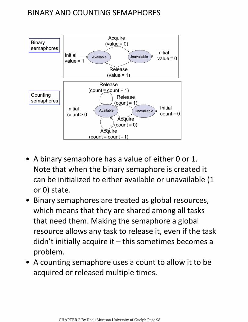
BINARY AND COUNTING SEMAPHORES
Binarysemaphores
Countingsemaphores
Acquire(value = 0)
Initialvalue = 0
Initialvalue = 1
Release(value = 1)
Available Unavailable
Release(count = count + 1)
Acquire(count = count - 1)
Acquire(count = 0)
Release(count = 1)
Initial count = 0
Initial count > 0
Available Unavailable
A binary semaphore has a value of either 0 or 1. •Note that when the binary semaphore is created it can be initialized to either available or unavailable (1 or 0) state.Binary semaphores are treated as global resources, which means that they are shared among all tasks that need them. Making the semaphore a global resource allows any task to release it, even if the task didn’t initially acquire it – this sometimes becomes a problem.
•
A counting semaphore uses a count to allow it to be acquired or released multiple times.
•
CHAPTER 2 By Radu Muresan University of Guelph Page 98
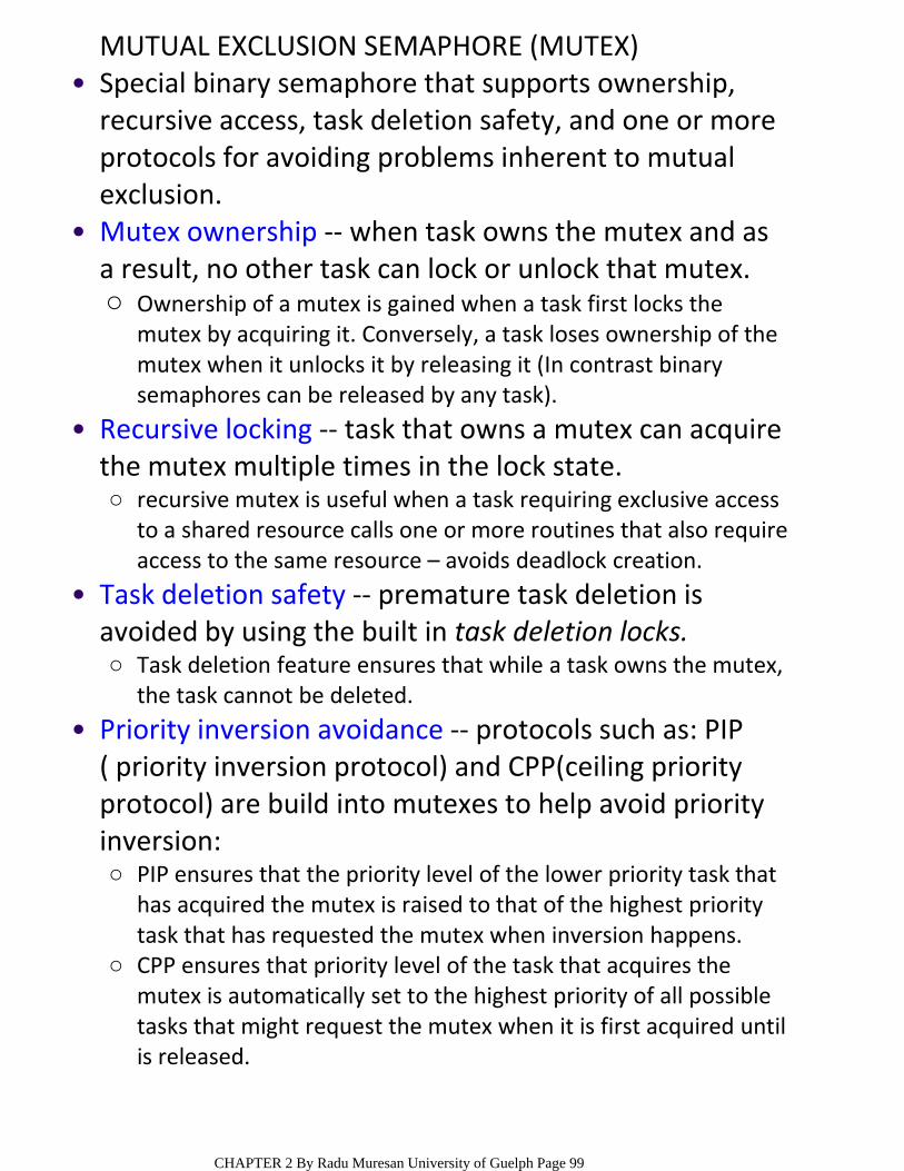
MUTUAL EXCLUSION SEMAPHORE (MUTEX)Special binary semaphore that supports ownership, recursive access, task deletion safety, and one or more protocols for avoiding problems inherent to mutual exclusion.
•
Ownership of a mutex is gained when a task first locks the mutex by acquiring it. Conversely, a task loses ownership of the mutex when it unlocks it by releasing it (In contrast binary semaphores can be released by any task).
○
Mutex ownership ‐‐ when task owns the mutex and as a result, no other task can lock or unlock that mutex.
•
recursive mutex is useful when a task requiring exclusive access to a shared resource calls one or more routines that also require access to the same resource – avoids deadlock creation.
○
Recursive locking ‐‐ task that owns a mutex can acquire the mutex multiple times in the lock state.
•
Task deletion feature ensures that while a task owns the mutex, the task cannot be deleted.
○
Task deletion safety ‐‐ premature task deletion is avoided by using the built in task deletion locks.
•
PIP ensures that the priority level of the lower priority task that has acquired the mutex is raised to that of the highest priority task that has requested the mutex when inversion happens.
○
CPP ensures that priority level of the task that acquires the mutex is automatically set to the highest priority of all possible tasks that might request the mutex when it is first acquired until is released.
○
Priority inversion avoidance ‐‐ protocols such as: PIP ( priority inversion protocol) and CPP(ceiling priority protocol) are build into mutexes to help avoid priority inversion:
•
CHAPTER 2 By Radu Muresan University of Guelph Page 99

OPERATIONS PERFORMED ON A SEMAPHORE
INITIALIZE (also called CREATE)○WAIT (also called PEND)○SIGNAL (also called POST)○
The operations performed on a semaphore are:•
The initial value of the semaphore must be provided when the semaphore is initialized.
•
The waiting list of tasks is always initially empty.•
ACQUIRING A SEMAPHORE
if the semaphore is available (the semaphore value is greater than 0) the semaphore value is decremented and the task continue execution.
○
if semaphore’s value is 0, the task performing WAIT is placed in a waiting list.
○
A task desiring a semaphore performs a WAIT operation.
•
most kernels allow to specify a timeout for the wait•
CHAPTER 2 By Radu Muresan University of Guelph Page 100
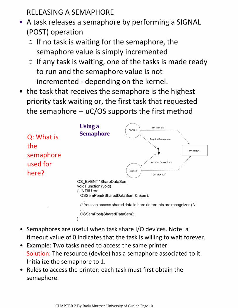
RELEASING A SEMAPHORE
If no task is waiting for the semaphore, the semaphore value is simply incremented
○
If any task is waiting, one of the tasks is made ready to run and the semaphore value is not incremented ‐ depending on the kernel.
○
A task releases a semaphore by performing a SIGNAL (POST) operation
•
the task that receives the semaphore is the highest priority task waiting or, the first task that requested the semaphore ‐‐ uC/OS supports the first method
•
Using a Semaphore
OS_EVENT *ShareDataSemvoid Function (void){ INT8U err;
OSSemPend(SharedDataSem, 0, &err);...
/* You can access shared data in here (interrupts are recognized) */...OSSemPost(SharedDataSem);
}
TASK 1
TASK 2
PRINTER
“I am task #1!”
Acquire Semaphore
Acquire Semaphore
“I am task #2!”
Semaphores are useful when task share I/O devices. Note: a timeout value of 0 indicates that the task is willing to wait forever.
•
Example: Two tasks need to access the same printer.•Solution: The resource (device) has a semaphore associated to it. Initialize the semaphore to 1.Rules to access the printer: each task must first obtain the semaphore.
•
Q: What is the semaphore used for here?
CHAPTER 2 By Radu Muresan University of Guelph Page 101

EXAMPLE OF SEMAPHORE MANAGEMENT AND OPERATIONS FOR uC/OS
a 16‐bit unsigned integer used to hold the semaphore count (0 to 65,535),
○
a list of tasks waiting for the semaphore count to be greater than 0.
○
uC/OS semaphores consist of two elements: •
uC/OS provides 6 services to access semaphores: OSSemAccept(), OSSemCreate(), OSSemDel(),OSSemPend(), OSSemPost() and OSSemQuery().
•
FUNCTION CALLS•
OS_EVENT *OSSemCreate (INT16U cnt)OS_EVENT *OSSemDel (OS_EVENT *pevent,
INT8U opt, INT8U *err)void OSSemPend (OS_EVENT *pevent, INT16U timeout,
INT8U *err)INT8U OSSemPost (OS_EVENT *pevent)INT16U OSSemAccept (OS_EVENT *pevent)INT8U OSSemQuery (OS_EVENT *pevent,
OS_SEM_DATA *pdata)
OSSemCreate(), OSSemPend(), and OSSemPost() cannot be individually disabled as can the other services. That’s because they are always needed when you enable uC/OS semaphore management.
○
To enable the other services individually you must set the corresponding constant to 1, specifically: OS_SEM_ACCEPT_EN, OS_SEM_DEL_EN, OS_SEM_QUERRY_EN.
○
The above services are enabled when OS_SEM‐EN is set to 1 ‐‐ Note that the underlined services can be individually disabled.
•
CHAPTER 2 By Radu Muresan University of Guelph Page 102
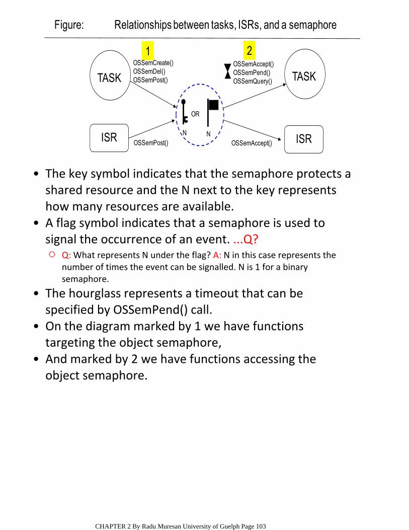
1 2
ISR
TASK
ISR
TASK
OR
N NOSSemAccept()
OSSemAccept()OSSemPend()OSSemQuery()
OSSemCreate()OSSemDel()OSSemPost()
OSSemPost()
Figure: Relationships between tasks, ISRs, and a semaphore
The key symbol indicates that the semaphore protects a•shared resource and the N next to the key represents how many resources are available.
Q: What represents N under the flag? A: N in this case represents the number of times the event can be signalled. N is 1 for a binary semaphore.
○
A flag symbol indicates that a semaphore is used to signal the occurrence of an event. ...Q?
•
The hourglass represents a timeout that can be specified by OSSemPend() call.
•
On the diagram marked by 1 we have functions targeting the object semaphore,
•
And marked by 2 we have functions accessing the object semaphore.
•
CHAPTER 2 By Radu Muresan University of Guelph Page 103
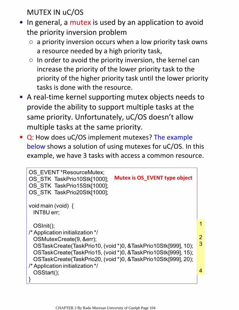
MUTEX IN uC/OS
a priority inversion occurs when a low priority task owns a resource needed by a high priority task,
○
In order to avoid the priority inversion, the kernel can increase the priority of the lower priority task to the priority of the higher priority task until the lower priority tasks is done with the resource.
○
In general, a mutex is used by an application to avoid the priority inversion problem
•
A real‐time kernel supporting mutex objects needs to provide the ability to support multiple tasks at the same priority. Unfortunately, uC/OS doesn’t allow multiple tasks at the same priority.
•
Q: How does uC/OS implement mutexes? The example below shows a solution of using mutexes for uC/OS. In this example, we have 3 tasks with access a common resource.
•
OS_EVENT *ResourceMutex;OS_STK TaskPrio10Stk[1000];OS_STK TaskPrio15Stk[1000];OS_STK TaskPrio20Stk[1000];
void main (void) {INT8U err;
OSInit();/* Application initialization */
OSMutexCreate(9, &err);OSTaskCreate(TaskPrio10, (void *)0, &TaskPrio10Stk[999], 10);OSTaskCreate(TaskPrio15, (void *)0, &TaskPrio10Stk[999], 15);OSTaskCreate(TaskPrio20, (void *)0, &TaskPrio10Stk[999], 20);
/* Application initialization */OSStart();
}
1
23
4
Mutex is OS_EVENT type object
CHAPTER 2 By Radu Muresan University of Guelph Page 104
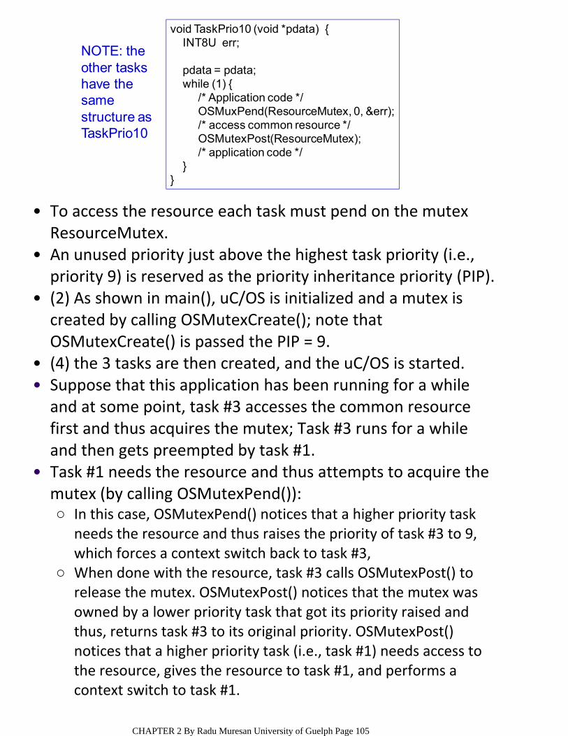
To access the resource each task must pend on the mutex ResourceMutex.
•
An unused priority just above the highest task priority (i.e., priority 9) is reserved as the priority inheritance priority (PIP).
•
(2) As shown in main(), uC/OS is initialized and a mutex is created by calling OSMutexCreate(); note that OSMutexCreate() is passed the PIP = 9.
•
(4) the 3 tasks are then created, and the uC/OS is started. •Suppose that this application has been running for a while and at some point, task #3 accesses the common resource first and thus acquires the mutex; Task #3 runs for a while and then gets preempted by task #1.
•
In this case, OSMutexPend() notices that a higher priority task needs the resource and thus raises the priority of task #3 to 9, which forces a context switch back to task #3,
○
When done with the resource, task #3 calls OSMutexPost() to release the mutex. OSMutexPost() notices that the mutex was owned by a lower priority task that got its priority raised and thus, returns task #3 to its original priority. OSMutexPost() notices that a higher priority task (i.e., task #1) needs access to the resource, gives the resource to task #1, and performs a context switch to task #1.
○
Task #1 needs the resource and thus attempts to acquire the mutex (by calling OSMutexPend()):
•
void TaskPrio10 (void *pdata) {INT8U err;
pdata = pdata;while (1) {
/* Application code */OSMuxPend(ResourceMutex, 0, &err);/* access common resource */OSMutexPost(ResourceMutex);/* application code */
}}
NOTE: the other tasks have the same structure as TaskPrio10
CHAPTER 2 By Radu Muresan University of Guelph Page 105

CHAPTER 2 By Radu Muresan University of Guelph Page 106
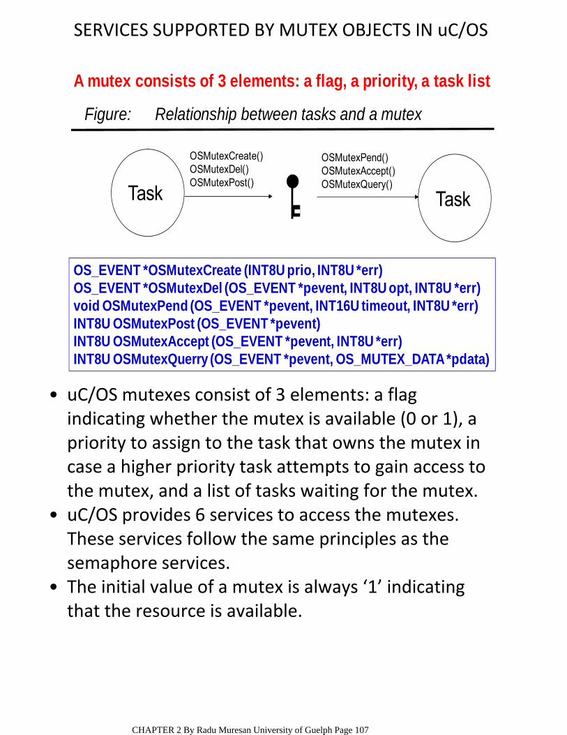
SERVICES SUPPORTED BY MUTEX OBJECTS IN uC/OS
OS_EVENT *OSMutexCreate (INT8U prio, INT8U *err)OS_EVENT *OSMutexDel (OS_EVENT *pevent, INT8U opt, INT8U *err)void OSMutexPend (OS_EVENT *pevent, INT16U timeout, INT8U *err)INT8U OSMutexPost (OS_EVENT *pevent)INT8U OSMutexAccept (OS_EVENT *pevent, INT8U *err)INT8U OSMutexQuerry (OS_EVENT *pevent, OS_MUTEX_DATA *pdata)
A mutex consists of 3 elements: a flag, a priority, a task list
OSMutexCreate() OSMutexDel()OSMutexPost()
OSMutexPend() OSMutexAccept()OSMutexQuery()
Task Task
Figure: Relationship between tasks and a mutex
uC/OS mutexes consist of 3 elements: a flag indicating whether the mutex is available (0 or 1), a priority to assign to the task that owns the mutex in case a higher priority task attempts to gain access to the mutex, and a list of tasks waiting for the mutex.
•
uC/OS provides 6 services to access the mutexes. These services follow the same principles as the semaphore services.
•
The initial value of a mutex is always ‘1’ indicating that the resource is available.
•
CHAPTER 2 By Radu Muresan University of Guelph Page 107

COMMUNICATION OBJECTS ‐‐MASSAGE MAILBOXESMessages can be sent to a task through kernel services. A message mailbox, also called a message exchange, is typically a pointer‐size variable.
•
Through a service provided by the kernel, a task or an ISR can deposit a message (the pointer) into this mailbox.
•
Similarly, one or more tasks can receive messages through a service provided by the kernel. Both the sender and receiving task agree on what the pointer is actually pointing to.
•
A waiting list is associated with each mailbox in case more than one task wants to receive messages through the mailbox.
•
A task desiring a message from an empty mailbox is suspended and placed on the waiting list until a message is received.
•
Typically, the kernel allows the task waiting for a message to specify a timeout. If a message is not received before the timeout expires, the requesting task is made ready to run, and an error code (indicating that a timeout has occurred) is returned to it.
•
When a message is deposited into the mailbox, either the highest priority task waiting for the message is given the message (priority‐based), or the first task to request a message is given the message (FIFO).
•
uC/OS support the highest priority mechanism. •
Task Task10
POST PEND
Mailbox
CHAPTER 2 By Radu Muresan University of Guelph Page 108
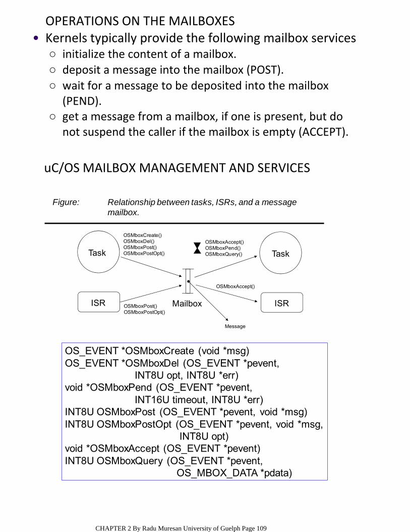
OPERATIONS ON THE MAILBOXES
initialize the content of a mailbox.○deposit a message into the mailbox (POST).○wait for a message to be deposited into the mailbox (PEND).
○
get a message from a mailbox, if one is present, but do not suspend the caller if the mailbox is empty (ACCEPT).
○
Kernels typically provide the following mailbox services•
uC/OS MAILBOX MANAGEMENT AND SERVICES
OSMboxPost()OSMboxPostOpt()
OSMboxCreate()OSMboxDel()OSMboxPost()OSMboxPostOpt()
OSMboxAccept()OSMboxPend()OSMboxQuery()
OSMboxAccept()
Message
Mailbox
Task Task
ISR ISR
Figure: Relationship between tasks, ISRs, and a messagemailbox.
OS_EVENT *OSMboxCreate (void *msg)OS_EVENT *OSMboxDel (OS_EVENT *pevent,
INT8U opt, INT8U *err)void *OSMboxPend (OS_EVENT *pevent,
INT16U timeout, INT8U *err)INT8U OSMboxPost (OS_EVENT *pevent, void *msg)INT8U OSMboxPostOpt (OS_EVENT *pevent, void *msg,
INT8U opt)void *OSMboxAccept (OS_EVENT *pevent)INT8U OSMboxQuery (OS_EVENT *pevent,
OS_MBOX_DATA *pdata)
CHAPTER 2 By Radu Muresan University of Guelph Page 109

MESSAGE QUEUESA message queue is used to send one or more messages to a task – is an array of mailboxes.
•
The messages are extracted in FIFO fashion or LIFO fashion.
•
A waiting list is associated with the queue ‐‐ highest priority task waiting or FIFO will get the message.
•
10POST PEND
Queue
0
Interrupt ISR TASK
initialize the queue (queue empty after initialization).
○
deposit a message into the queue (POST).○wait for a message to be deposited into the queue (PEND).
○
get a message from a queue, if one is present, but do not suspend the caller if the mailbox is empty (ACCEPT).
○
Kernels typically provide these message queue services:
•
CHAPTER 2 By Radu Muresan University of Guelph Page 110
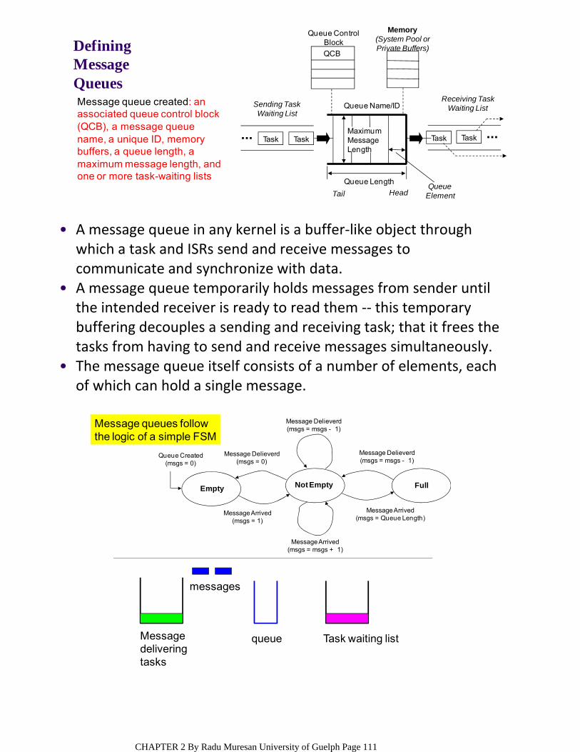
Defining Message QueuesMessage queue created: an associated queue control block (QCB), a message queue name, a unique ID, memory buffers, a queue length, a maximum message length, and one or more task-waiting lists
Memory(System Pool orPrivate Buffers)
Task Task Task TaskMaximumMessageLength
Sending TaskWaiting List
Queue ControlBlock
QCB
Queue Name/ID
Queue Length
HeadTailQueue
Element
Receiving TaskWaiting List
A message queue in any kernel is a buffer‐like object through which a task and ISRs send and receive messages to communicate and synchronize with data.
•
A message queue temporarily holds messages from sender until the intended receiver is ready to read them ‐‐ this temporary buffering decouples a sending and receiving task; that it frees the tasks from having to send and receive messages simultaneously.
•
The message queue itself consists of a number of elements, each of which can hold a single message.
•
Message queues follow the logic of a simple FSM
Message deliveringtasks
queue
messages
Task waiting list
Empty Not Empty Full
Queue Created(msgs = 0)
Message Delieverd(msgs = 0)
Message Delieverd(msgs = msgs - 1)
Message Delieverd(msgs = msgs - 1)
Message Arrived(msgs = msgs + 1)
Message Arrived(msgs = Queue Length)
Message Arrived(msgs = 1)
CHAPTER 2 By Radu Muresan University of Guelph Page 111
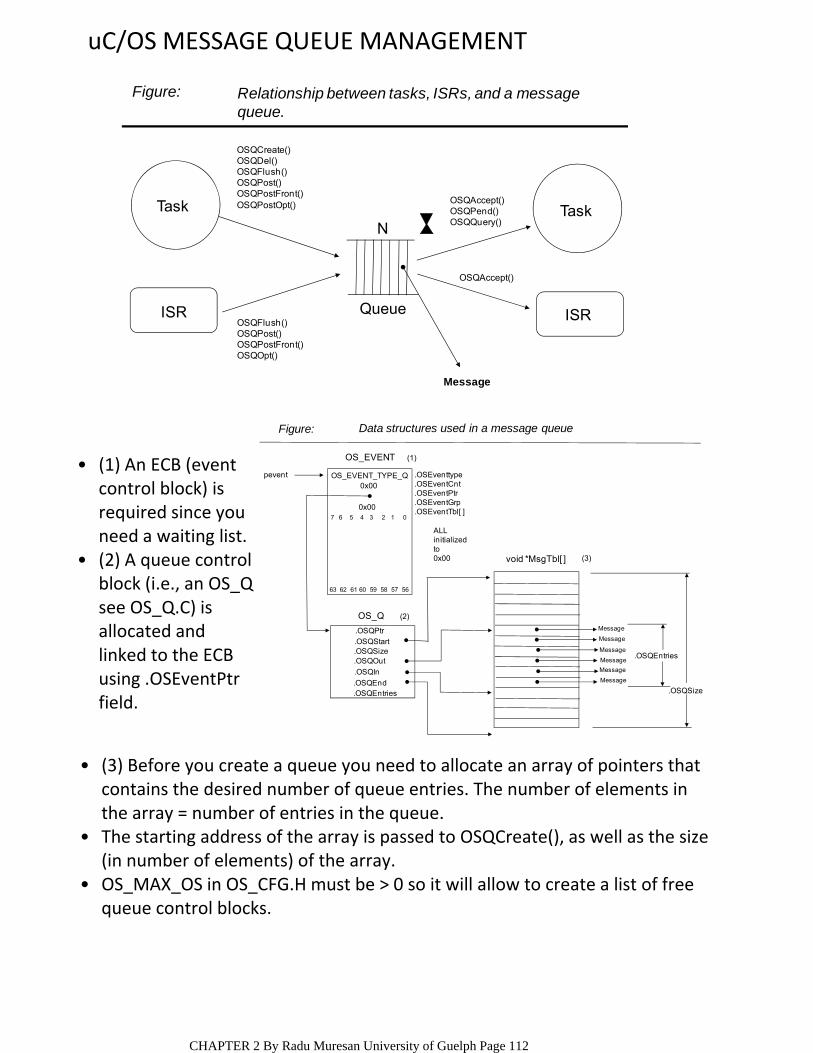
uC/OS MESSAGE QUEUE MANAGEMENT
Relationship between tasks, ISRs, and a messagequeue.
Figure:
ISR ISR
TaskTask
N
Queue
OSQCreate()OSQDel()OSQFlush()OSQPost()OSQPostFront()OSQPostOpt()
OSQFlush()OSQPost()OSQPostFront()OSQOpt()
OSQAccept()OSQPend()OSQQuery()
OSQAccept()
Message
Message
Message
Message
Message
Message
Message
.OSQPtr.OSQStart.OSQSize.OSQOut
.OSQEnd
.OSQIn
.OSQEntries
.OSEventtype
.OSEventCnt
.OSEventPtr
.OSEventGrp
.OSEventTbl[ ]
ALLinitializedto0x00
pevent
(3)
(1)
(2)OS_Q
OS_EVENT
void *MsgTbl[ ]
.OSQEntries
.OSQSize
OS_EVENT_TYPE_Q0x00
0x007 6 5 4 3 2 1 0
63 62 61 60 59 58 57 56
Figure: Data structures used in a message queue
(1) An ECB (event control block) is required since you need a waiting list.
•
(2) A queue control block (i.e., an OS_Q see OS_Q.C) is allocated and linked to the ECB using .OSEventPtr field.
•
(3) Before you create a queue you need to allocate an array of pointers that contains the desired number of queue entries. The number of elements in the array = number of entries in the queue.
•
The starting address of the array is passed to OSQCreate(), as well as the size (in number of elements) of the array.
•
OS_MAX_OS in OS_CFG.H must be > 0 so it will allow to create a list of free queue control blocks.
•
CHAPTER 2 By Radu Muresan University of Guelph Page 112
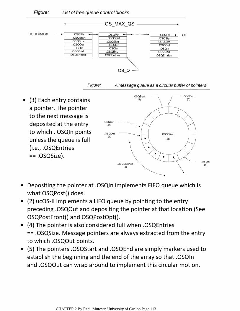
.OSQPtr
.OSQSize.OSQOut
.OSQEnd.OSQIn
.OSQStart
.OSQEntries
.OSQPtr
.OSQSize.OSQOut
.OSQEnd.OSQIn
.OSQStart
.OSQEntries
.OSQPtr
.OSQSize.OSQOut
.OSQEnd.OSQIn
.OSQStart
.OSQEntries
0OSQFreeList
OS_MAX_QS
OS_Q
Figure: List of free queue control blocks.
.OSQSize
(3)
.OSQOut(2)
.OSQOut(4)
.OSQStart(5)
.OSQEnd(5)
.OSQIn(1).OSQEnteries
(3)
Figure: A message queue as a circular buffer of pointers
Depositing the pointer at .OSQIn implements FIFO queue which is what OSQPost() does.
•
(2) ucOS‐II implements a LIFO queue by pointing to the entry preceding .OSQOut and depositing the pointer at that location (See OSQPostFront() and OSQPostOpt().
•
(4) The pointer is also considered full when .OSQEntries == .OSQSize. Message pointers are always extracted from the entry to which .OSQOut points.
•
(5) The pointers .OSQStart and .OSQEnd are simply markers used to establish the beginning and the end of the array so that .OSQIn and .OSQOut can wrap around to implement this circular motion.
•
(3) Each entry contains a pointer. The pointer to the next message is deposited at the entry to which . OSQIn points unless the queue is full (i.e., .OSQEntries == .OSQSize).
•
CHAPTER 2 By Radu Muresan University of Guelph Page 113
PRIORITY INVERSION PROBLEM IN RTOSA priority is assigned to each task ‐‐ the more important the task, the higher the priority given to it.
•
The application designer is responsible for deciding what priority each task gets.
•
STATIC PRIORITIES ‐‐ task priorities are static when the priority of each task does not change during the application’s execution ‐‐ all the tasks and their timing constraints are known at compile time and each task gets a fixed priority at compile time.
•
DYNAMIC PRIORITIES ‐‐ Task priorities are dynamic if the priority of tasks can be changed during the application’s execution ‐‐ each task can change its priority at run time. This feature is desirable to have in real‐time kernels to avoid priority inversions.
•
PRIORITY INVERSION PROBLEM ‐‐
Priority inversion is a problem in real‐time system and occurs mostly when you use a real‐time kernel.
○
May be caused by semaphore usage, device conflicts, bad design of interrupt handlers, poor programming and system design.
○
Priority inversion is a situation in which a low‐priority task executes while a higher priority task waits on it due to resource contentions.
•
ENGG4420 ‐‐ CHAPTER 2 ‐‐ LECTURE 8October‐25‐103:50 PM
CHAPTER 2 By Radu Muresan University of Guelph Page 114

Task 1 has a higher priority than Task 2, which in turn has
a higher priority than Task 3.
Example 1
Task 1 (H)
Task 2 (M)
Task 3 (L)
(11)
(9)
Task 2 Preempts Task 3(8)
(7)
Task 1 tries to get Semaphore(6)
(5)
Task 1 Preempts Task 3(4)
(3)(1)
Task 3 Gets a Semaphore(2) Task 3 Resumes
(10)
Task 3 Releases the Semaphore(12)
(13)
Priority Inversion
(1) Task 1 and Task 2 are both waiting for an event to occur and Task 3 is executing. (2) At some point, Task 3 acquires a semaphore, which the task needs before it can access a shared resource. (3) Task 3 performs some operations on the acquired resource. (4) The event for which Task 1 was waiting occurs, and thus the kernel suspends Task 3 and starts executing Task 1 because Task 1 has a higher priority. (5) Task 1 executes for a while until it also wants to access the resource at (6) (i.e. it attempts to get the semaphore that Task 3 owns). Because Task 3 owns the resource, Task 1 is placed in a list of tasks waiting for the kernel to free the semaphore. (7) Task 3 resumes and continues execution until it is preempted by Task 2 at (8) because the event for which Task 2 was waiting occurred. (9) Task 2 handles the event for which it was waiting, and when it’s done, the kernel relinquishes the CPU back to Task 3 at (10). During (11) Task 3 finishes working with the resource and releases the semaphore at (12). At this point, the kernel knows that a higher priority task is waiting for the semaphore and performs a context switch to resume Task 1. During (13) Task 1 has the semaphore and can access the shared resource.
•
In this scenario the priority of Task 1 has been virtually reduced to that of Task 3.
•
CHAPTER 2 By Radu Muresan University of Guelph Page 115
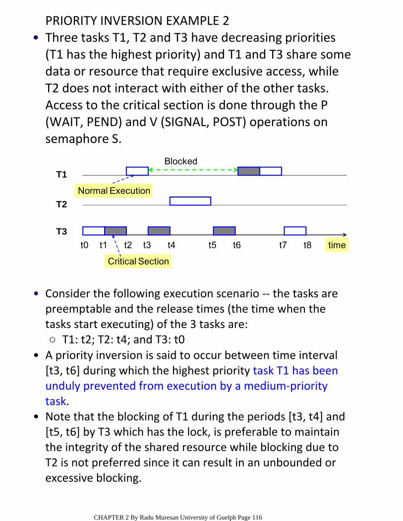
PRIORITY INVERSION EXAMPLE 2Three tasks T1, T2 and T3 have decreasing priorities (T1 has the highest priority) and T1 and T3 share some data or resource that require exclusive access, while T2 does not interact with either of the other tasks. Access to the critical section is done through the P (WAIT, PEND) and V (SIGNAL, POST) operations on semaphore S.
•
T3
T2
T1
t0 t1 t2 t4 t5 t6 t7 t8t3
Critical Section
Blocked
Normal Execution
time
T1: t2; T2: t4; and T3: t0○
Consider the following execution scenario ‐‐ the tasks are preemptable and the release times (the time when the tasks start executing) of the 3 tasks are:
•
A priority inversion is said to occur between time interval [t3, t6] during which the highest priority task T1 has been unduly prevented from execution by a medium‐priority task.
•
Note that the blocking of T1 during the periods [t3, t4] and [t5, t6] by T3 which has the lock, is preferable to maintain the integrity of the shared resource while blocking due to T2 is not preferred since it can result in an unbounded or excessive blocking.
•
CHAPTER 2 By Radu Muresan University of Guelph Page 116
PRIORITY INHERITANCE PROTOCOL (PIP)The problem of priority inversion in real‐time systems has been studied intensively for both fixed‐priority and dynamic‐priority scheduling.
•
One result is: the priority inheritance protocol that offers a simple solution to the problem of unbounded priority inversion.
•
In the PIP the priority of tasks are dynamically changed so that the priority of any task in a critical region gets the priority of the highest task pending on that same critical region. In particular when a task T blocks one or more higher‐priority tasks, it temporarily inherits the highest priority of the blocked tasks.
•
HIGHLIGHTS OF THE PIPThe highest‐priority task T gives up the processor whenever it seeks to lock the semaphore guarding a critical section that is already locked by some other task.
•
When T2 exits the critical section that caused the block, it reverts to the priority it had when it entered that section.
○
If a task T1 is blocked by T2 and , T1 > T2 (i.e., T1 has precedence over task T2), task T2 inherits the priority of T1 as long as it blocks T1.
•
If T3 blocks T2, which blocks T1, (with T1 > T2 > T3) then T3 inherits the priority of T1 via T2.
○Priority inheritance is transitive. •
CHAPTER 2 By Radu Muresan University of Guelph Page 117
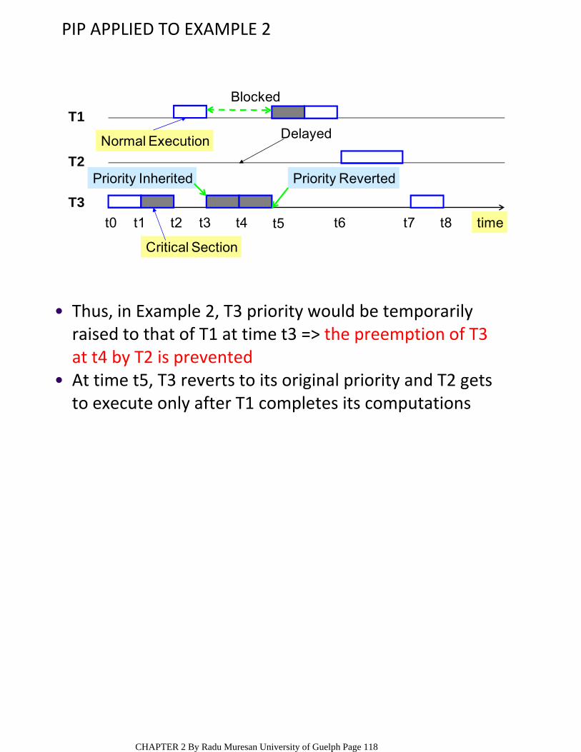
PIP APPLIED TO EXAMPLE 2
T3
T2
T1
t0 t1 t2 t4 t5 t6 t7 t8t3
Critical Section
Blocked
Normal Execution
time
Priority Inherited Priority Reverted
Delayed
Thus, in Example 2, T3 priority would be temporarily raised to that of T1 at time t3 => the preemption of T3 at t4 by T2 is prevented
•
At time t5, T3 reverts to its original priority and T2 gets to execute only after T1 completes its computations
•
CHAPTER 2 By Radu Muresan University of Guelph Page 118
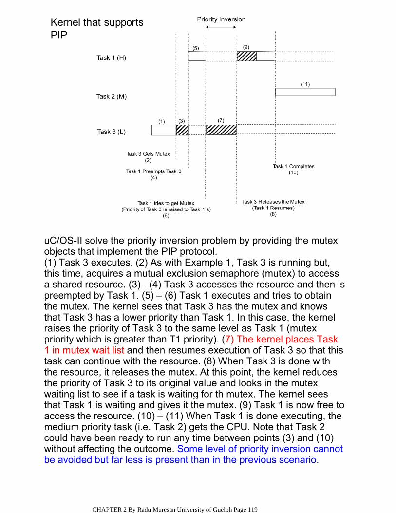
Kernel that supportsPIP
(11)
(9)
Task 3 Releases the Mutex(Task 1 Resumes)
(8)
(7)
Task 1 tries to get Mutex(Priority of Task 3 is raised to Task 1’s)
(6)
(5)
Task 1 Preempts Task 3(4)
(3)(1)
Task 3 Gets Mutex(2)
Task 1 Completes(10)
Priority Inversion
Task 1 (H)
Task 2 (M)
Task 3 (L)
uC/OS-II solve the priority inversion problem by providing the mutexobjects that implement the PIP protocol.(1) Task 3 executes. (2) As with Example 1, Task 3 is running but, this time, acquires a mutual exclusion semaphore (mutex) to access a shared resource. (3) - (4) Task 3 accesses the resource and then is preempted by Task 1. (5) – (6) Task 1 executes and tries to obtain the mutex. The kernel sees that Task 3 has the mutex and knows that Task 3 has a lower priority than Task 1. In this case, the kernel raises the priority of Task 3 to the same level as Task 1 (mutex priority which is greater than T1 priority). (7) The kernel places Task 1 in mutex wait list and then resumes execution of Task 3 so that this task can continue with the resource. (8) When Task 3 is done with the resource, it releases the mutex. At this point, the kernel reduces the priority of Task 3 to its original value and looks in the mutex waiting list to see if a task is waiting for th mutex. The kernel sees that Task 1 is waiting and gives it the mutex. (9) Task 1 is now free to access the resource. (10) – (11) When Task 1 is done executing, the medium priority task (i.e. Task 2) gets the CPU. Note that Task 2 could have been ready to run any time between points (3) and (10) without affecting the outcome. Some level of priority inversion cannot be avoided but far less is present than in the previous scenario.
CHAPTER 2 By Radu Muresan University of Guelph Page 119
DEADLOCK
Assume task T1 has exclusive access to resource R1 and task T2 has exclusive access to resource R2. If T1 needs exclusive access to R2 and T2 needs exclusive access to R1, neither task can continue –they are deadlocked.
○
A deadlock also called a deadly embrace, is a situation in which two tasks are each unknowingly waiting for resources held by the other.
•
acquire all resources before proceeding, ○acquire the resources in the same order, and release resources in the reverse order. …Q1?
○
(1) The simplest way to avoid deadlock is for tasks to:•
Most kernels allow you to specify a timeout when acquiring a semaphore so the deadlock can be broken. …Q2?
•
Q1: How do the techniques presented at (1) solve the deadlock problem?
•
A. Tasks don’t lock when they are in the wait state; In the example if we acquire, release resources in order R1, R2. This makes the tasks acquire and release the resources in the same order and as a result the tasks can’t deadlock. Q2: How the deadlock is broken by having the timeout specified, and what are the implications of this method?
•
A: If the semaphore is not available within a certain amount of time, the task requesting the resource resumes execution. Some form of error code must be returned to the task to notify it that a timeout occurred. A return error code prevents the task from thinking it has obtained the resource. Deadlocks generally occur in multitasking systems, not in embedded systems.
CHAPTER 2 By Radu Muresan University of Guelph Page 120
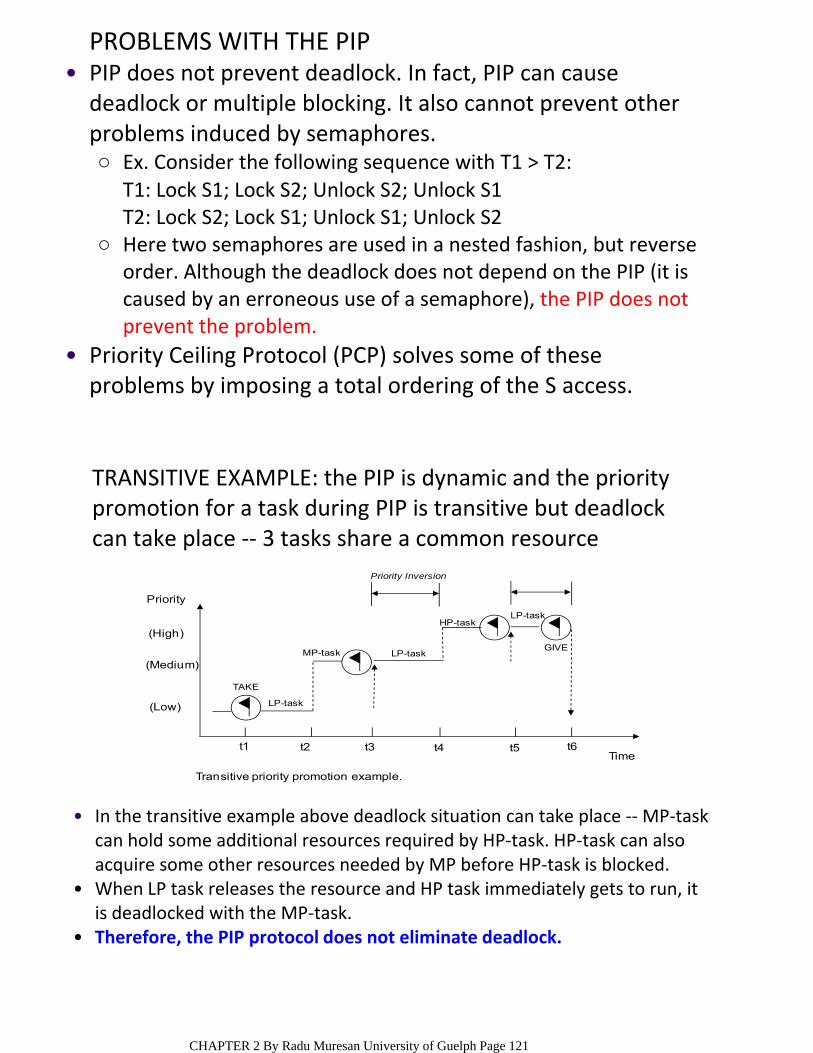
PROBLEMS WITH THE PIP
Ex. Consider the following sequence with T1 > T2:○T1: Lock S1; Lock S2; Unlock S2; Unlock S1T2: Lock S2; Lock S1; Unlock S1; Unlock S2Here two semaphores are used in a nested fashion, but reverse order. Although the deadlock does not depend on the PIP (it is caused by an erroneous use of a semaphore), the PIP does not prevent the problem.
○
PIP does not prevent deadlock. In fact, PIP can cause deadlock or multiple blocking. It also cannot prevent other problems induced by semaphores.
•
Priority Ceiling Protocol (PCP) solves some of these problems by imposing a total ordering of the S access.
•
Priority
(High)
(Medium)
(Low) LP-task
LP-task
LP-taskHP-task
MP-task
TAKE
Priority Inversion
GIVE
Transitive priority promotion example.
t1 t2 t3 t4 t5 t6Time
TRANSITIVE EXAMPLE: the PIP is dynamic and the priority promotion for a task during PIP is transitive but deadlock can take place ‐‐ 3 tasks share a common resource
In the transitive example above deadlock situation can take place ‐‐MP‐task can hold some additional resources required by HP‐task. HP‐task can also acquire some other resources needed by MP before HP‐task is blocked.
•
When LP task releases the resource and HP task immediately gets to run, it is deadlocked with the MP‐task.
•
Therefore, the PIP protocol does not eliminate deadlock.•
CHAPTER 2 By Radu Muresan University of Guelph Page 121
PRIORITY CEILING PROTOCOL (PCP)
To achieve this, each resource is assigned a priority (the priority ceiling) equal to the priority of the highest priority task that can use it.
○
The Priority Ceiling Protocol extends the Priority Inheritance Protocol through chained blocking in such a way that no task can enter a critical section in a way that leads to blocking it.
•
The Priority Ceiling Protocol is the same as the Priority Inheritance Protocol, except that a task, T, can also be blocked from entering a critical section if there exists any semaphore currently held by some other task whose priority ceiling is greater than or equal to the priority of T.
•
In the PCP, the priority of every task is known, as are the resources required by every task.
•
Example 1: R is required by 4 tasks (T1 of priority 4, T2 of priority 9, T3 of priority 10 and T4 of priority 8). As a result the priority ceiling of R is 4.
○
For a given resource the priority ceiling is the highest priority of all possible tasks that might require the resource.
•
Example 2: A system has 4 resources. R1: PC=4, R2: PC=9, R3: PC=10; R4: PC=8. As a result the current priority ceiling of the system is 4.
○
The current priority ceiling for a running system at any given time is the highest priority ceiling of all of resources in use at that time
•
CHAPTER 2 By Radu Muresan University of Guelph Page 122
PRIORITY CEILING PROTOCOL RULES
(1) If R is in use, T is blocked,○(2) If R is free and if the priority of T is higher than the current priority ceiling, R is allocated to T,
○
(3) If the current priority ceiling belongs to one of the resources that T currently holds, R is allocated to T, and otherwise T is blocked,
○
(4) The task that blocks T inherits T’s priority if it is higher and executes at this priority until it releases every resource whose priority ceiling is higher than or equal to T’s priority. The task then returns to its previous priority.
○
The following rules apply when a task T requests a resource R:
•
In PCP a requesting task can be blocked for one of 3 causes. •The first cause is when the resource is currently in use, which is direct resource contention blocking, and is the result of rule (1).
1.
The second cause is when the blocking task has inherited a higher priority and its current execution priority is higher than that of the requesting task. This cause is priority inheritance blocking and is the result of rule (4).
2.
A task can be blocked when its priority is lower than the current priority ceiling even when the requested resource if free. This cause is priority ceiling blocking and is a direct consequence of the “otherwise” clause of rule (3). Rule (3) prevents a task from blocking itself if it holds a resource that has defined the current priority ceiling.
3.
CHAPTER 2 By Radu Muresan University of Guelph Page 123

PCP CHARACTERISTICSThe PCP has 3 characteristics:•A requesting task can be blocked by only one task; therefore, the blocking interval is at most the duration of the critical section,
1.
Transitive blocking never occurs under the PCP,2.Deadlock never occurs under the PCP.3.One of the deadlock preventions strategies is to impose ordering on the resources.
•
This issue occurs because otherwise the current priority ceiling would be either equal to or higher than the priority of T, which implies that tasks with a priority higher than T’s do not require the resources currently in use.
○
Consequently, none of the tasks that are holding resources in use can inherit a higher priority, preempt task T, and then request a resource that T holds. This feature prevents the circular‐wait condition. This feature is also why deadlock cannot occur when using the PCP as an access control protocol.
○
The same induction process shows that the condition in which a task blocks another task but is in turn blocked by a third task, transitive blocking, does not occur under the PCP.
○
The resource ordering can be realized by using the priority ceilings of the resources. Rule (2) says if the priority of T is higher than the current priority ceiling, T does not require any resources that are in use.
•
CHAPTER 2 By Radu Muresan University of Guelph Page 124
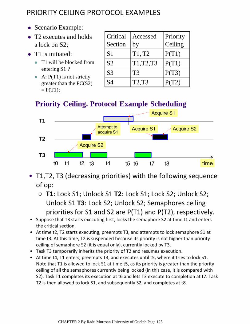
PRIORITY CEILING PROTOCOL EXAMPLES
T1: Lock S1; Unlock S1 T2: Lock S1; Lock S2; Unlock S2; Unlock S1 T3: Lock S2; Unlock S2; Semaphores ceiling priorities for S1 and S2 are P(T1) and P(T2), respectively.
○
T1,T2, T3 (decreasing priorities) with the following sequence of op:
•
Suppose that T3 starts executing first, locks the semaphore S2 at time t1 and enters the critical section.
•
At time t2, T2 starts executing, preempts T3, and attempts to lock semaphore S1 at time t3. At this time, T2 is suspended because its priority is not higher than priority ceiling of semaphore S2 (it is equal only), currently locked by T3.
•
Task T3 temporarily inherits the priority of T2 and resumes execution. •At time t4, T1 enters, preempts T3, and executes until t5, where it tries to lock S1. Note that T1 is allowed to lock S1 at time t5, as its priority is greater than the priority ceiling of all the semaphores currently being locked (in this case, it is compared with S2). Task T1 completes its execution at t6 and lets T3 execute to completion at t7. Task T2 is then allowed to lock S1, and subsequently S2, and completes at t8.
•
Priority Ceiling. Protocol Example Scheduling
T3
T2
T1
t0 t1 t2 t4 t5 t6 t7 t8t3
Acquire S1
time
Attempt toacquire S1
Acquire S1 Acquire S2
Acquire S2
Scenario Example:
T2 executes and holds a lock on S2;
T1 is initiated: T1 will be blocked from
entering S1 ?
A: P(T1) is not strictly greater than the PC(S2) = P(T1);
Critical Section
Accessed by
Priority Ceiling
S1 T1, T2 P(T1)
S2 T1,T2,T3 P(T1)
S3 T3 P(T3)
S4 T2,T3 P(T2)
CHAPTER 2 By Radu Muresan University of Guelph Page 125

TYPICAL MESSAGE QUEUE USEThe following are typical ways to use message queues within an application: 1) non‐interlocked, one‐way data communication; 2) interlocked, one‐way data communication; 3) interlocked, two‐way data communication; 4) broadcast communication
•
Non-interlocked, one-way data communication
The activities of tSourceTask and tSinkTask are not synchronized
tSourceTask (){
...Send message to
message queue...
}
tSinkTask (){
...Receive message from
message queue...
}
Sending task Receiving task
tSourceTask TSinkTask
The type of communication is also called non‐interlocked (or loosely coupled), one‐way data communication. The activities of tSourceTask and tSinkTask are not synchronized. tsourceTask simply sends a message; it does not require acknowledgment from tSinkTask.
•
Q: What happen if tSinkTask has a higher or a lower priority? A: If tSinkTask is set to a higher priority, it runs first until it blocks on an empty message queue. As soon as tSourceTask sends a message to the queue, tSinkTask receives the message and starts to execute again.
•
If tSinkTask is set to a lower priority, tSourceTask fills the message queue with messages. Eventually, tSourceTask can be made to block when sending a message to a full message queue.
•
ISRs typically use non‐interlocked, one‐way communication. Remember, when ISRs send messages to the message queue, they must do so in a non‐blocking way. If the message queue becomes full, any additional messages that the ISR sends tot the message queue are lost.
•
One of the simplest scenarios for message‐based communications requires a sending task (also called the message source), a message queue, and a receiving task (also called a message sink), as illustrated in this figure.
•
ENGG4420 ‐‐ CHAPTER 2 ‐‐ HOMEWORKOctober‐26‐1011:44 AM
CHAPTER 2 By Radu Muresan University of Guelph Page 126
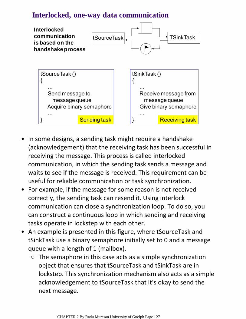
Interlocked, one-way data communication
Interlocked communication is based on the handshake process
tSourceTask (){
...Send message to
message queueAcquire binary semaphore...
} Sending task
tSinkTask (){
...Receive message from
message queueGive binary semaphore...
} Receiving task
tSourceTask TSinkTask
In some designs, a sending task might require a handshake (acknowledgement) that the receiving task has been successful in receiving the message. This process is called interlocked communication, in which the sending task sends a message and waits to see if the message is received. This requirement can be useful for reliable communication or task synchronization.
•
For example, if the message for some reason is not received correctly, the sending task can resend it. Using interlock communication can close a synchronization loop. To do so, you can construct a continuous loop in which sending and receiving tasks operate in lockstep with each other.
•
The semaphore in this case acts as a simple synchronization object that ensures that tSourceTask and tSinkTask are in lockstep. This synchronization mechanism also acts as a simple acknowledgement to tSourceTask that it’s okay to send the next message.
○
An example is presented in this figure, where tSourceTask and tSinkTask use a binary semaphore initially set to 0 and a message queue with a length of 1 (mailbox).
•
CHAPTER 2 By Radu Muresan University of Guelph Page 127
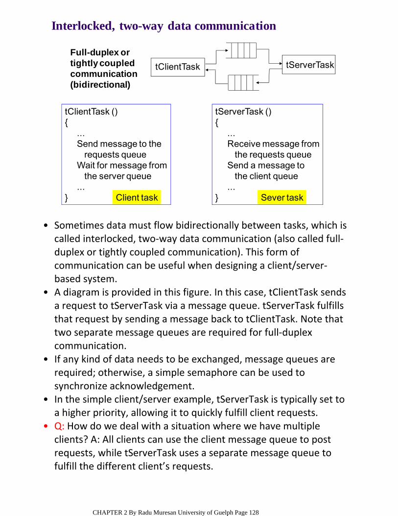
Sometimes data must flow bidirectionally between tasks, which is called interlocked, two‐way data communication (also called full‐duplex or tightly coupled communication). This form of communication can be useful when designing a client/server‐based system.
•
A diagram is provided in this figure. In this case, tClientTask sends a request to tServerTask via a message queue. tServerTask fulfills that request by sending a message back to tClientTask. Note that two separate message queues are required for full‐duplex communication.
•
If any kind of data needs to be exchanged, message queues are required; otherwise, a simple semaphore can be used to synchronize acknowledgement.
•
In the simple client/server example, tServerTask is typically set to a higher priority, allowing it to quickly fulfill client requests.
•
Q: How do we deal with a situation where we have multiple clients? A: All clients can use the client message queue to post requests, while tServerTask uses a separate message queue to fulfill the different client’s requests.
•
Interlocked, two-way data communication
Full-duplex or tightly coupled communication (bidirectional)
tClientTask (){
...Send message to the
requests queueWait for message from
the server queue...
} Client task
tServerTask (){
...Receive message from
the requests queueSend a message to
the client queue...
} Sever task
tServerTasktClientTask
CHAPTER 2 By Radu Muresan University of Guelph Page 128
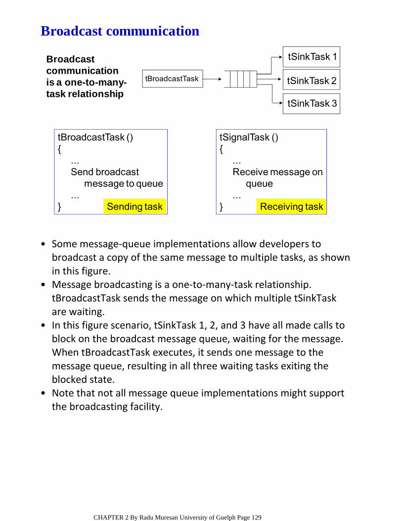
Some message‐queue implementations allow developers to broadcast a copy of the same message to multiple tasks, as shown in this figure.
•
Message broadcasting is a one‐to‐many‐task relationship. tBroadcastTask sends the message on which multiple tSinkTask are waiting.
•
In this figure scenario, tSinkTask 1, 2, and 3 have all made calls to block on the broadcast message queue, waiting for the message. When tBroadcastTask executes, it sends one message to the message queue, resulting in all three waiting tasks exiting the blocked state.
•
Note that not all message queue implementations might support the broadcasting facility.
•
Broadcast communication is a one-to-many-task relationship
tBroadcastTask (){
...Send broadcast
message to queue...
} Sending task
tSignalTask (){
...Receive message on
queue...
} Receiving task
tSinkTask 1
tSinkTask 2
tSinkTask 3
tBroadcastTask
Broadcast communication
CHAPTER 2 By Radu Muresan University of Guelph Page 129

SUMMARY OF COMMON PRACTICAL DESIGN PATTERNS ‐‐ HOMEWORKSynchronous activity synchronization1.Asynchronous event notification using signals2.Resource synchronization3.
Task1 Task 2binary semaphore
ISR Task 2binary semaphore
Interrupt
Task-to-task synchronization using binary semaphores
ISR-to-task synchronization using binary semaphores
(1) Synchronous activity synchronization
Task1 Task 2
event register1 0 0 0 0 0
Task-to-task synchronization using event registers
ISR-to-task synchronization using event registers
ISR Task 2
event register
1 0 0 0 0 0
Interrupt
CHAPTER 2 By Radu Muresan University of Guelph Page 130
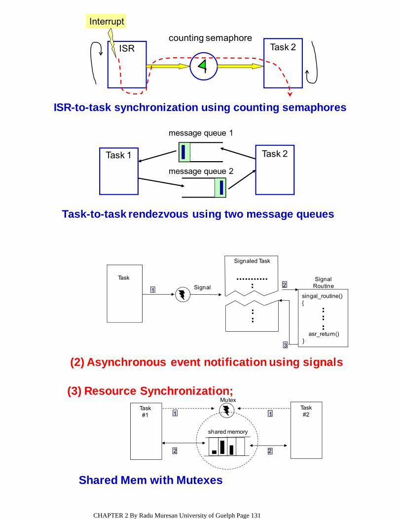
ISR Task 2counting semaphore
Interrupt
Task 1 Task 2
message queue 1
message queue 2
ISR-to-task synchronization using counting semaphores
Task-to-task rendezvous using two message queues
(2) Asynchronous event notification using signals
Shared Mem with Mutexes
(3) Resource Synchronization;Mutex
shared memory
1
2 2
1Task#1
Task#2
Task
12
3
Signaled Task
singal_routine(){
asr_return()}
SignalRoutineSignal
CHAPTER 2 By Radu Muresan University of Guelph Page 131
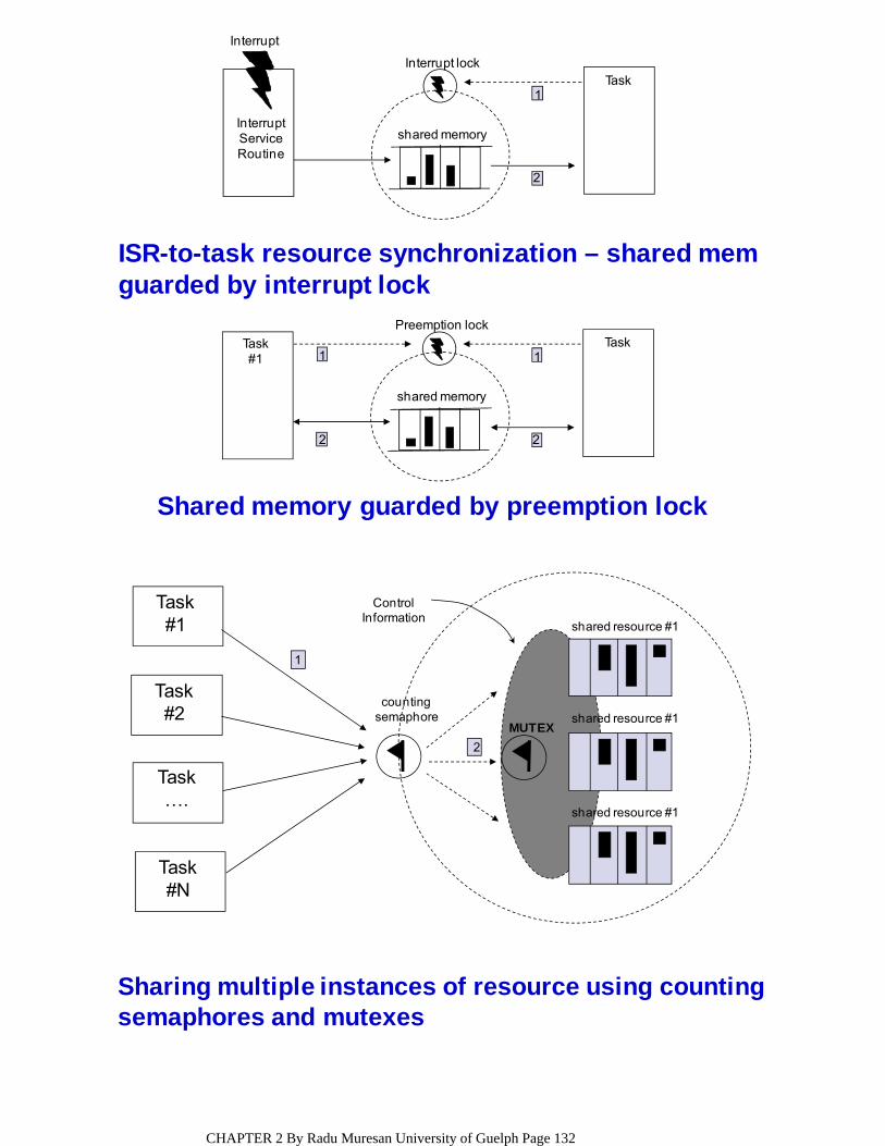
ISR-to-task resource synchronization – shared memguarded by interrupt lock
Shared memory guarded by preemption lock
Preemption lock
shared memory
1
2 2
1Task#1
Task
Interrupt lock
shared memory
2
1
InterruptServiceRoutine
Task
Interrupt
Sharing multiple instances of resource using countingsemaphores and mutexes
Task#1
Task#2
Task….
Task#N
ControlInformation
countingsemaphore
1
2
MUTEX
shared resource #1
shared resource #1
shared resource #1
CHAPTER 2 By Radu Muresan University of Guelph Page 132
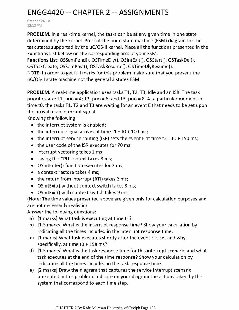
PROBLEM. In a real‐time kernel, the tasks can be at any given time in one state determined by the kernel. Present the finite state machine (FSM) diagram for the task states supported by the uC/OS‐II kernel. Place all the functions presented in the Functions List bellow on the corresponding arcs of your FSM.Functions List: OSSemPend(), OSTimeDly(), OSIntExit(), OSStart(), OSTaskDel(), OSTaskCreate, OSSemPost(), OSTaskResume(), OSTimeDlyResume().NOTE: In order to get full marks for this problem make sure that you present the uC/OS‐II state machine not the general 3 states FSM.
PROBLEM. A real‐time application uses tasks T1, T2, T3, Idle and an ISR. The task priorities are: T1_prio = 4; T2_prio = 6; and T3_prio = 8. At a particular moment in time t0, the tasks T1, T2 and T3 are waiting for an event E that needs to be set upon the arrival of an interrupt signal.
the interrupt system is enabled; the interrupt signal arrives at time t1 = t0 + 100 ms;the interrupt service routing (ISR) sets the event E at time t2 = t0 + 150 ms;the user code of the ISR executes for 70 ms;interrupt vectoring takes 1 ms;saving the CPU context takes 3 ms;OSIntEnter() function executes for 2 ms;a context restore takes 4 ms;the return from interrupt (RTI) takes 2 ms;OSIntExit() without context switch takes 3 ms;OSIntExit() with context switch takes 9 ms;
Knowing the following:
(Note: The time values presented above are given only for calculation purposes and are not necessarily realistic)
[1 marks] What task is executing at time t1?a)[1.5 marks] What is the interrupt response time? Show your calculation by indicating all the times included in the interrupt response time.
b)
[1 marks] What task executes shortly after the event E is set and why, specifically, at time t0 + 158 ms?
c)
[1.5 marks] What is the task response time for this interrupt scenario and what task executes at the end of the time response? Show your calculation by indicating all the times included in the task response time.
d)
[2 marks] Draw the diagram that captures the service interrupt scenario presented in this problem. Indicate on your diagram the actions taken by the system that correspond to each time step.
e)
Answer the following questions:
ENGG4420 ‐‐ CHAPTER 2 ‐‐ ASSIGNMENTSOctober‐26‐1012:12 PM
CHAPTER 2 By Radu Muresan University of Guelph Page 133
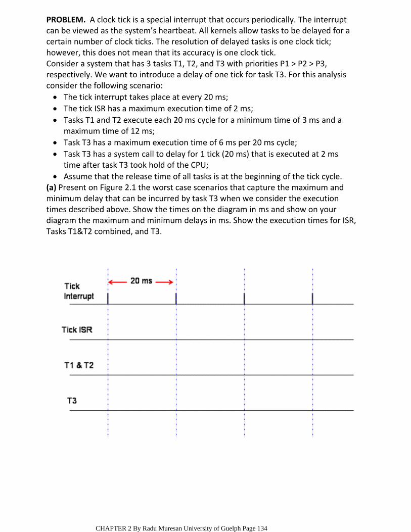
PROBLEM. A clock tick is a special interrupt that occurs periodically. The interrupt can be viewed as the system’s heartbeat. All kernels allow tasks to be delayed for a certain number of clock ticks. The resolution of delayed tasks is one clock tick; however, this does not mean that its accuracy is one clock tick.
The tick interrupt takes place at every 20 ms;The tick ISR has a maximum execution time of 2 ms;Tasks T1 and T2 execute each 20 ms cycle for a minimum time of 3 ms and a maximum time of 12 ms;
Task T3 has a maximum execution time of 6 ms per 20 ms cycle;Task T3 has a system call to delay for 1 tick (20 ms) that is executed at 2 ms time after task T3 took hold of the CPU;
Assume that the release time of all tasks is at the beginning of the tick cycle.
Consider a system that has 3 tasks T1, T2, and T3 with priorities P1 > P2 > P3, respectively. We want to introduce a delay of one tick for task T3. For this analysis consider the following scenario:
(a) Present on Figure 2.1 the worst case scenarios that capture the maximum and minimum delay that can be incurred by task T3 when we consider the execution times described above. Show the times on the diagram in ms and show on your diagram the maximum and minimum delays in ms. Show the execution times for ISR, Tasks T1&T2 combined, and T3.
CHAPTER 2 By Radu Muresan University of Guelph Page 134
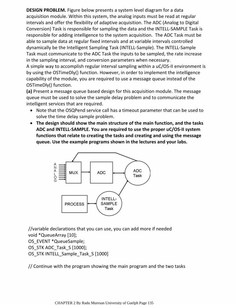
DESIGN PROBLEM. Figure below presents a system level diagram for a data acquisition module. Within this system, the analog inputs must be read at regular intervals and offer the flexibility of adaptive acquisition. The ADC (Analog to Digital Conversion) Task is responsible for sampling the data and the INTELL‐SAMPLE Task is responsible for adding intelligence to the system acquisition. The ADC Task must be able to sample data at regular fixed intervals and at variable intervals controlled dynamically be the Intelligent Sampling Task (INTELL‐Sample). The INTELL‐Sample Task must communicate to the ADC Task the inputs to be sampled, the rate increase in the sampling interval, and conversion parameters when necessary.A simple way to accomplish regular interval sampling within a uC/OS‐II environment is by using the OSTimeDly() function. However, in order to implement the intelligence capability of the module, you are required to use a message queue instead of the OSTimeDly() function.
Note that the OSQPend service call has a timeout parameter that can be used to solve the time delay sample problem.
The design should show the main structure of the main function, and the tasks ADC and INTELL‐SAMPLE. You are required to use the proper uC/OS‐II system functions that relate to creating the tasks and creating and using the message queue. Use the example programs shown in the lectures and your labs.
(a) Present a message queue based design for this acquisition module. The message queue must be used to solve the sample delay problem and to communicate the intelligent services that are required.
//variable declarations that you can use, you can add more if neededvoid *QueueArray [10];OS_EVENT *QueueSample;OS_STK ADC_Task_S [1000];OS_STK INTELL_Sample_Task_S [1000]
// Continue with the program showing the main program and the two tasks
CHAPTER 2 By Radu Muresan University of Guelph Page 135
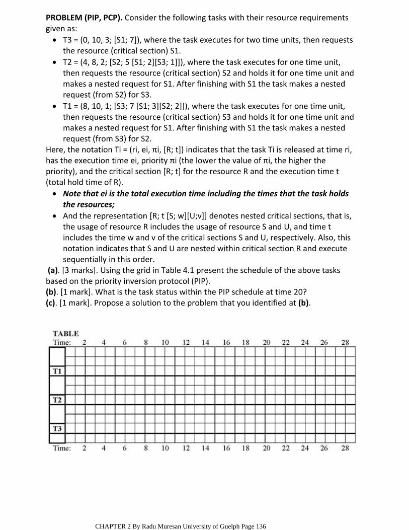
T3 = (0, 10, 3; [S1; 7]), where the task executes for two time units, then requests the resource (critical section) S1.
T2 = (4, 8, 2; [S2; 5 [S1; 2][S3; 1]]), where the task executes for one time unit, then requests the resource (critical section) S2 and holds it for one time unit and makes a nested request for S1. After finishing with S1 the task makes a nested request (from S2) for S3.
T1 = (8, 10, 1; [S3; 7 [S1; 3][S2; 2]]), where the task executes for one time unit, then requests the resource (critical section) S3 and holds it for one time unit and makes a nested request for S1. After finishing with S1 the task makes a nested request (from S3) for S2.
PROBLEM (PIP, PCP). Consider the following tasks with their resource requirements given as:
Note that ei is the total execution time including the times that the task holds the resources;
And the representation [R; t [S; w][U;v]] denotes nested critical sections, that is, the usage of resource R includes the usage of resource S and U, and time t includes the time w and v of the critical sections S and U, respectively. Also, this notation indicates that S and U are nested within critical section R and execute sequentially in this order.
Here, the notation Ti = (ri, ei, πi, [R; t]) indicates that the task Ti is released at time ri, has the execution time ei, priority πi (the lower the value of πi, the higher the priority), and the critical section [R; t] for the resource R and the execution time t (total hold time of R).
(a). [3 marks]. Using the grid in Table 4.1 present the schedule of the above tasks based on the priority inversion protocol (PIP).(b). [1 mark]. What is the task status within the PIP schedule at time 20?(c). [1 mark]. Propose a solution to the problem that you identified at (b).
CHAPTER 2 By Radu Muresan University of Guelph Page 136
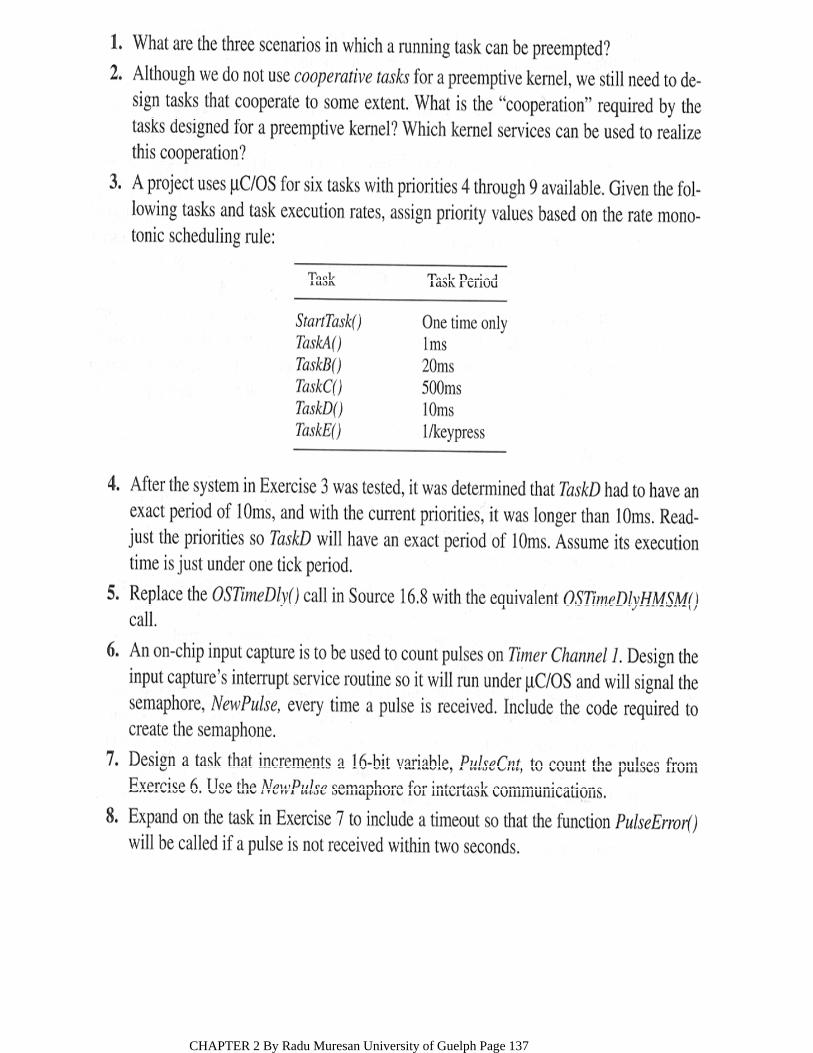
CHAPTER 2 By Radu Muresan University of Guelph Page 137

CHAPTER 2 By Radu Muresan University of Guelph Page 138

END OF CHAPTER 2
CHAPTER 2 By Radu Muresan University of Guelph Page 139