ENG6530 RCS1 ENG6530 Reconfigurable Computing Systems Hardware Description Languages VHDL.
61
ENG6530 RCS 1 ENG6530 ENG6530 Reconfigurable Computing Reconfigurable Computing Systems Systems Hardware Description Languages Hardware Description Languages VHDL VHDL
-
Upload
elfrieda-logan -
Category
Documents
-
view
227 -
download
0
Transcript of ENG6530 RCS1 ENG6530 Reconfigurable Computing Systems Hardware Description Languages VHDL.
ENG6530 RCS 1
ENG6530ENG6530Reconfigurable Reconfigurable
ComputingComputingSystemsSystems
Hardware Description Hardware Description Languages Languages
VHDLVHDL
ENG6530 RCS 2
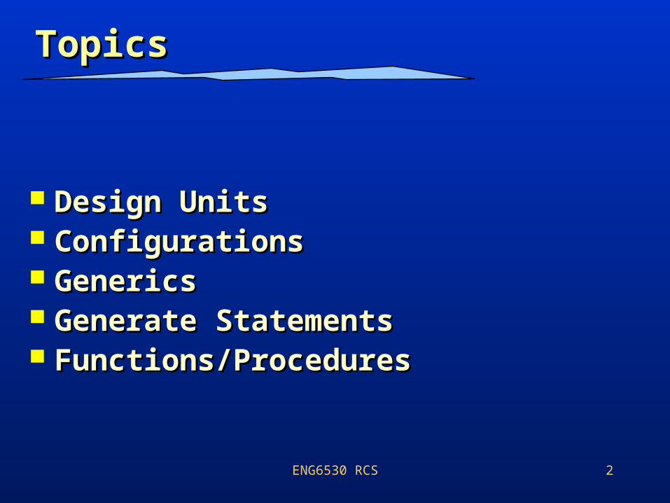
TopicsTopics
Design UnitsDesign Units ConfigurationsConfigurations GenericsGenerics Generate StatementsGenerate Statements Functions/ProceduresFunctions/Procedures
ENG6530 RCS 3
ReferencesReferences
– Peter Ashenden, “The designer’s guide to VHDL, 2nd edition”, Morgan Kaufmann publishers, 2002.
– Douglas Perry, “VHDL”, 3rd Edition, McGraw Hill.
– Sudhakar Yalamanchili, “Introductory VHDL: From Simulation to Synthesis”, Prentice Hall, 2001.
– Sudhakar Yalamnachili, “Sudhakar Yalamnachili, “VHDL: A VHDL: A Starter’s GuideStarter’s Guide”, 2”, 2ndnd Edition, Prentice Edition, Prentice Hall, 2005.Hall, 2005.
ENG6530 RCS 4
VHDL: Introduction VHDL: Introduction
• VHDL is an acronym for “VHSIC Hardware Description Language”.
• VHSIC is an acronym for “Very High Speed Integrated Circuits” program. It was a US government sponsored program that was responsible for developing a standard HDL.
• VHDL supports modeling and simulation of digital systems at various levels of design abstraction.
ENG6530 RCS 5
Design UnitsDesign Units
Design units are the fundamental building blocks in a VHDL program. When a program is processed, it is broken into individual design units and each unit is analyzed and stored independently.There are five kinds of design units
Entity declarationEntity declaration Architecture declarationArchitecture declaration Package declaration Package body Configuration
ENG6530 RCS 6
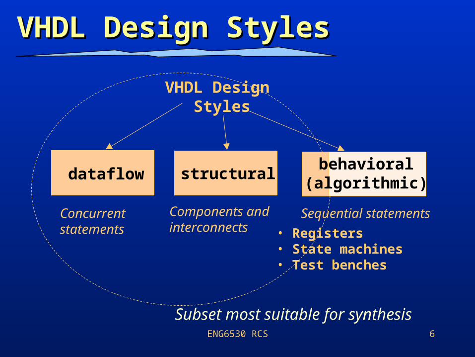
VHDL Design StylesVHDL Design Styles
Components andinterconnects
structural
VHDL Design Styles
dataflow
Concurrent statements
behavioral(algorithmic)
• Registers• State machines• Test benches
Sequential statements
Subset most suitable for synthesis
ENG6530 RCS 7
Dataflow Description Dataflow Description
Describes how data moves through the how data moves through the systemsystem and the various processing steps.
Data Flow uses series of concurrent statements to realize logic. Concurrent statements are evaluated at the same evaluated at the same timetime; thus, order of these statements doesn’t matter.
Data Flow is most useful style whenmost useful style when series of Boolean equations can represent a logic.
ENG6530 RCS 8
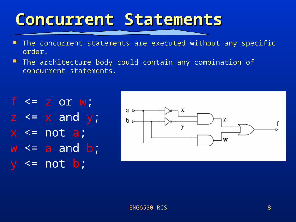
Concurrent StatementsConcurrent Statements The concurrent statements are executed without any specific order. The architecture body could contain any combination of concurrent
statements.
f <= z or w;z <= x and y;x <= not a;w <= a and b;y <= not b;
ENG6530 RCS 9
Elements of Structural Elements of Structural ModelsModels
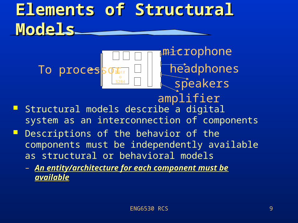
Structural models describe a digital system as an interconnection of components
Descriptions of the behavior of the components must be independently available as structural or behavioral models– An entity/architecture for each component An entity/architecture for each component
must be availablemust be available
Micro
3284
To processor
microphone
speakersheadphones
amplifier
ENG6530 RCS 10
Structural DescriptionStructural Description
Structural design is the simplestsimplest to understand.
This style is the closest to schematic captureschematic capture and utilizes simple building blocks to compose logic functions.
Components are interconnected in a hierarchical manner.
Structural descriptions may connect simple gates or complex, abstract components.
Structural style is useful whenis useful when expressing a design that is naturally composed of sub-blocks.
ENG6530 RCS 11
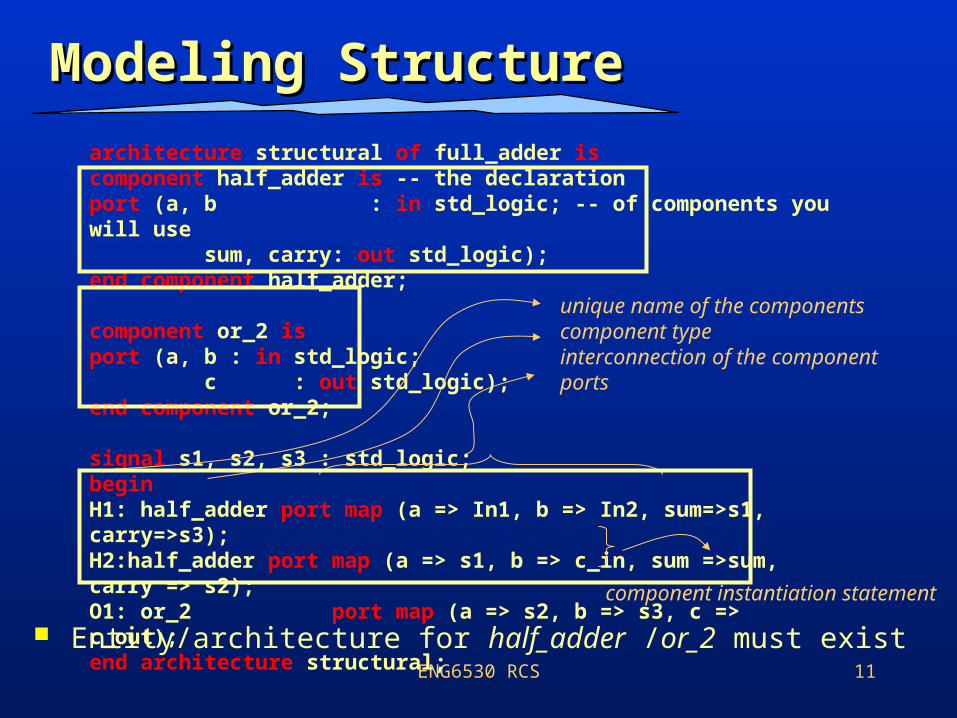
Modeling StructureModeling Structure
Entity/architecture for half_adder /or_2 must exist
architecture structural of full_adder iscomponent half_adder is -- the declarationport (a, b : in std_logic; -- of components you will use sum, carry: out std_logic);end component half_adder;
component or_2 isport (a, b : in std_logic; c : out std_logic);end component or_2;
signal s1, s2, s3 : std_logic;beginH1: half_adder port map (a => In1, b => In2, sum=>s1, carry=>s3);H2:half_adder port map (a => s1, b => c_in, sum =>sum, carry => s2);O1: or_2 port map (a => s2, b => s3, c => c_out);end architecture structural;
unique name of the componentscomponent typeinterconnection of the componentports
component instantiation statement
ENG6530 RCS 12
Behavioral (Process Behavioral (Process Construct)Construct)
Statements in a process are executed sequentially
A process body is structured much like conventional C function– Declaration and use of variables– if-then, if-then-else, case, for and while constructs– A process can contain signal assignment statements
A process executes concurrentlyexecutes concurrently with other concurrent signal assignment statements
A process takes 0 seconds of simulated time to executetakes 0 seconds of simulated time to execute and may schedule events in the future
We can think of a process as a complex signal complex signal assignmentassignment statement!
ENG6530 RCS 13
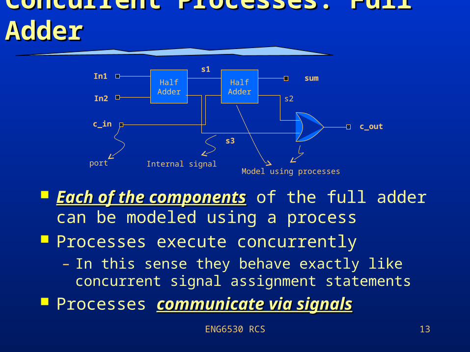
Concurrent Processes: Full Concurrent Processes: Full AdderAdder
Each of the componentsEach of the components of the full adder can be modeled using a process
Processes execute concurrently– In this sense they behave exactly like
concurrent signal assignment statements Processes communicate via signalscommunicate via signals
Half Adder
Half Adder
In1
In2
c_in
s1
s3
s2
sum
c_out
portModel using processes
Internal signal
ENG6530 RCS 14
Sequential StatementsSequential Statements
These statements can appear inside a process description:
• if-then-else• case• loop
• infinite loop• while loop• for loop
• assertion and report
• variable assignments• signal assignments• function and procedure calls
ENG6530 RCS 15
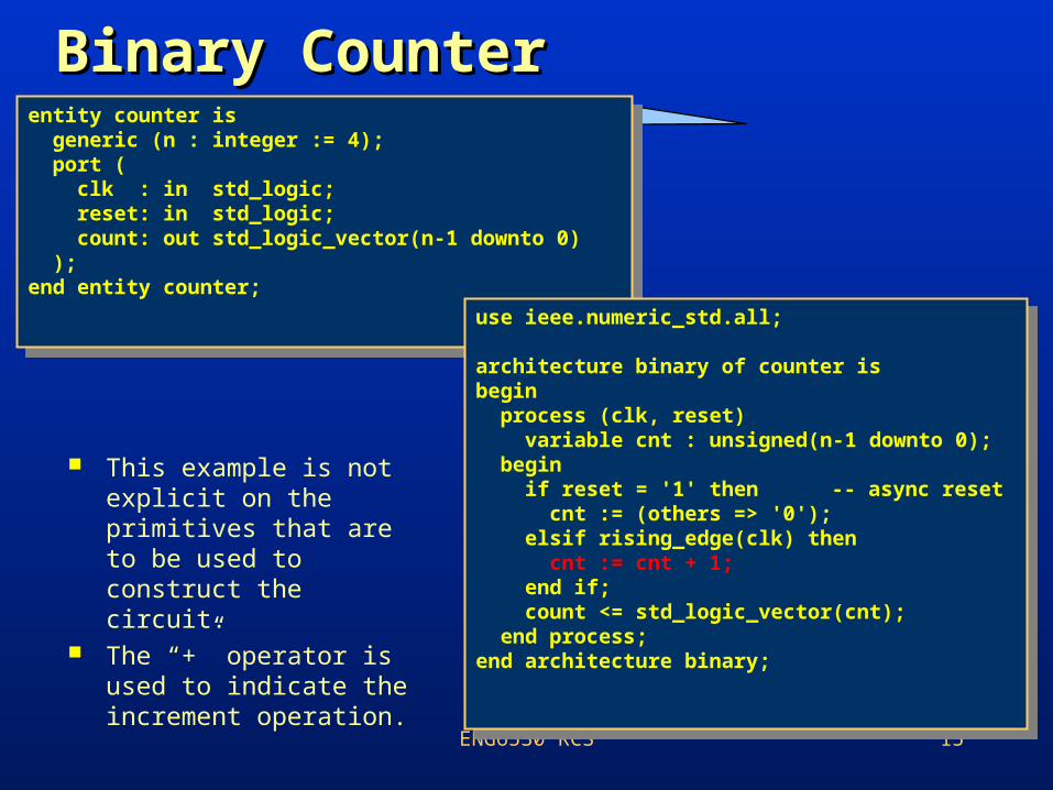
Binary CounterBinary Counter
This example is not explicit on the primitives that are to be used to construct the circuit.
The “+” operator is used to indicate the increment operation.
entity counter is generic (n : integer := 4); port ( clk : in std_logic; reset: in std_logic; count: out std_logic_vector(n-1 downto 0) );end entity counter;
entity counter is generic (n : integer := 4); port ( clk : in std_logic; reset: in std_logic; count: out std_logic_vector(n-1 downto 0) );end entity counter;
use ieee.numeric_std.all;
architecture binary of counter isbegin process (clk, reset) variable cnt : unsigned(n-1 downto 0); begin if reset = '1' then -- async reset cnt := (others => '0'); elsif rising_edge(clk) then cnt := cnt + 1; end if; count <= std_logic_vector(cnt); end process;end architecture binary;
ENG6530 RCS 16
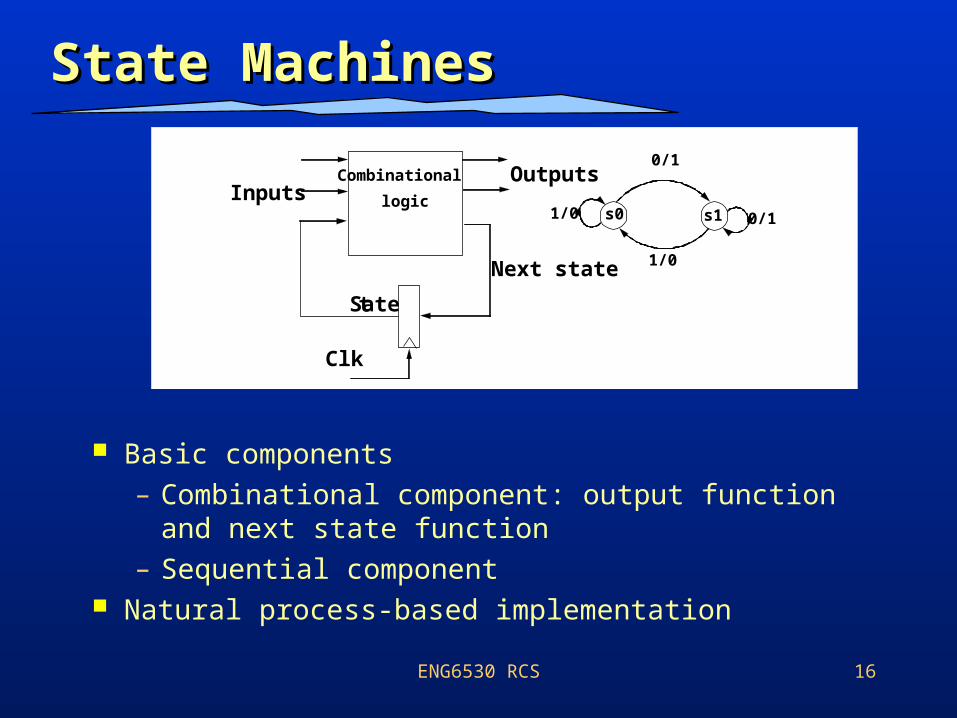
State MachinesState Machines
Basic components – Combinational component: output function and
next state function– Sequential component
Natural process-based implementation
Combinational
logicInputsOutputs
State
Clk
Next state
s0 s1 0/11/0
0/1
1/0
ENG6530 RCS 17
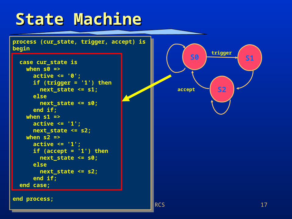
State Machine State Machine process (cur_state, trigger, accept) isbegin case cur_state is when s0 => active <= '0'; if (trigger = '1') then next_state <= s1; else next_state <= s0; end if; when s1 => active <= '1'; next_state <= s2; when s2 => active <= '1'; if (accept = '1') then next_state <= s0; else next_state <= s2; end if; end case;
end process;
process (cur_state, trigger, accept) isbegin case cur_state is when s0 => active <= '0'; if (trigger = '1') then next_state <= s1; else next_state <= s0; end if; when s1 => active <= '1'; next_state <= s2; when s2 => active <= '1'; if (accept = '1') then next_state <= s0; else next_state <= s2; end if; end case;
end process;
S0 S1
S2
trigger
accept
ENG6530 RCS 18
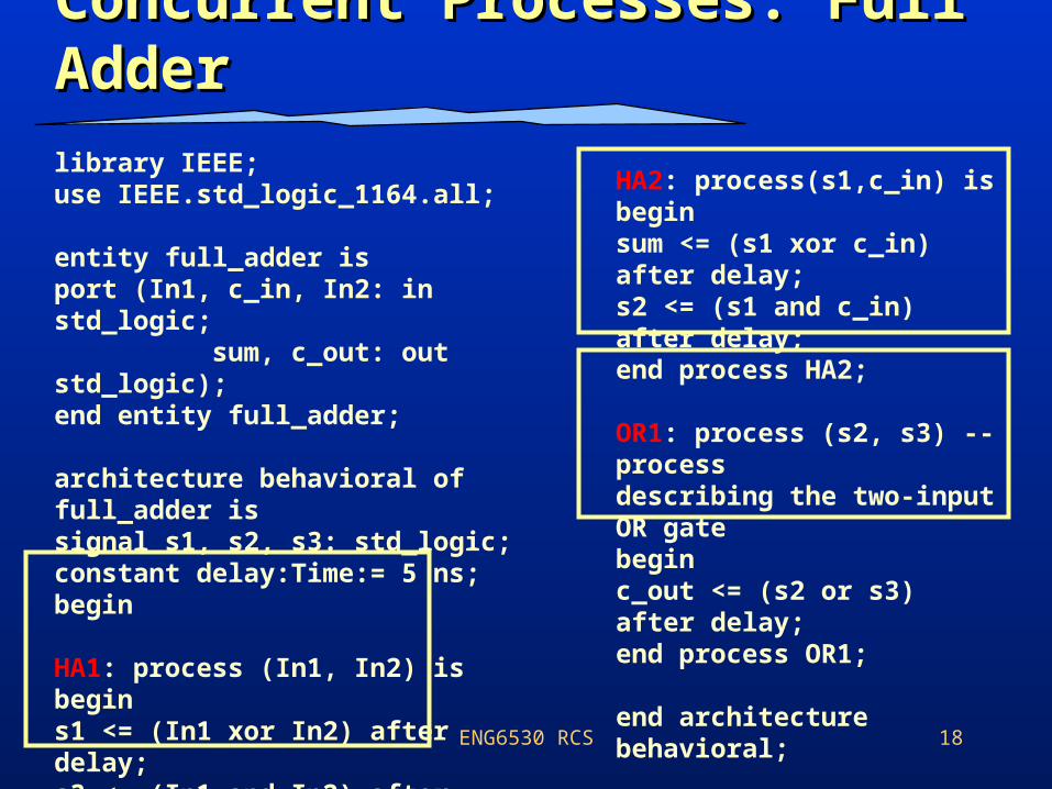
Concurrent Processes: Full Concurrent Processes: Full AdderAdder
library IEEE;use IEEE.std_logic_1164.all;
entity full_adder isport (In1, c_in, In2: in std_logic; sum, c_out: out std_logic);end entity full_adder;
architecture behavioral of full_adder issignal s1, s2, s3: std_logic;constant delay:Time:= 5 ns;begin
HA1: process (In1, In2) isbegins1 <= (In1 xor In2) after delay;s3 <= (In1 and In2) after delay;end process HA1;
HA2: process(s1,c_in) isbeginsum <= (s1 xor c_in) after delay;s2 <= (s1 and c_in) after delay;end process HA2;
OR1: process (s2, s3) -- processdescribing the two-input OR gatebeginc_out <= (s2 or s3) after delay;end process OR1;
end architecture behavioral;
ENG6530 RCS 19
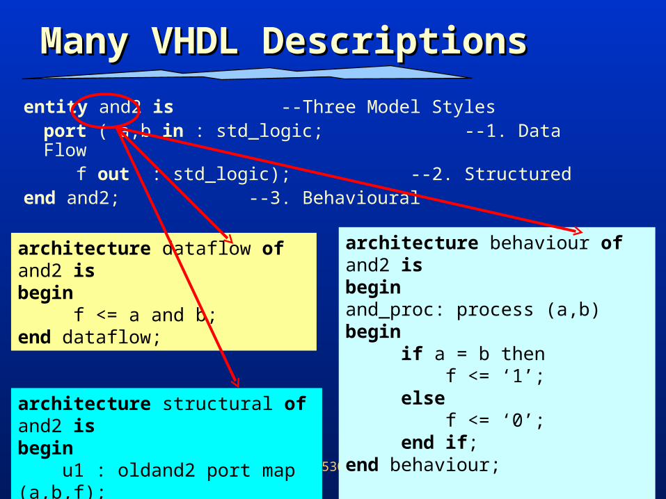
entity and2 is --Three Model Stylesport ( a,b in : std_logic; --1. Data Flow
f out : std_logic); --2. Structuredend and2; --3. Behavioural
Many VHDL DescriptionsMany VHDL Descriptions
architecture dataflow of and2 isbegin f <= a and b; end dataflow;
architecture structural of and2 isbegin u1 : oldand2 port map (a,b,f);end structured;
architecture behaviour of and2 isbeginand_proc: process (a,b)begin if a = b then f <= ‘1’; else f <= ‘0’; end if;end behaviour;
ENG6530 RCS 20
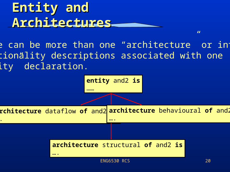
Entity and Entity and ArchitecturesArchitectures
There can be more than one “architecture” or internalfunctionality descriptions associated with one“entity” declaration.
entity and2 is……
architecture dataflow of and2 is….
architecture structural of and2 is….
architecture behavioural of and2 is….
ENG6530 RCS 21
ConfigurationsConfigurations
So far, we have seen that there are different ways in which to model the operation of digital circuit utilizing– Data flow– Behavioral– Structural
If you have different representations of one digital circuit (i.e. half adder or full adder).– Which architecture for the half adder should be
used? Is there a mechanism in VHDL to accomplish this?
ENG6530 RCS 22
ConfigurationsConfigurations
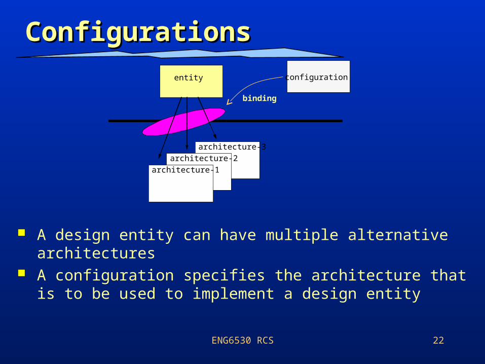
A design entity can have multiple alternative architectures
A configuration specifies the architecture that is to be used to implement a design entity
architecture-3
architecture-2
architecture-1
entity
binding
configuration
ENG6530 RCS 23
Configuration TechniquesConfiguration Techniques
The VHDL language provides configurations for explicitly associating an architecture description with each component in a structural model.– This process of association is referred to
as bindingbinding an instance of the component to an architecture.
– In the absence of any programmer-supplied configuration information, default bindingdefault binding rules apply.
ENG6530 RCS 24
Default Binding RulesDefault Binding Rules
If no configuration information is provided, then we can find a default architecture as follows:– If the entity name is the same as the component name,
then this entity is bound to the component.– If there are multiple architectures for the entity, then in
this case we use the last compiled architecture for the entity.
If no such entity with the same name is visible to the VHDL environment, then the binding is said to be deferreddeferred: that is no binding takes place now, but information will be forthcoming later.– This is akin to going ahead with wiring the rest of the
circuit and hoping that your partner comes up with the right chips before you are ready to run the experiment!!
25
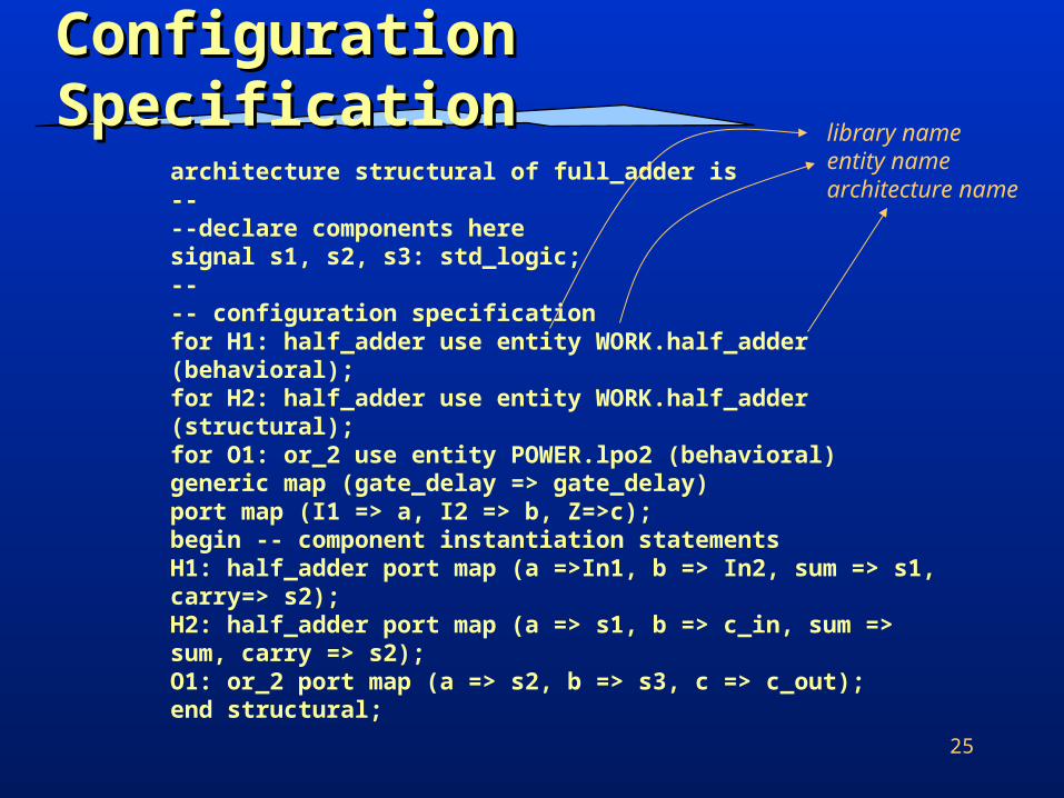
Configuration SpecificationConfiguration Specification
architecture structural of full_adder is----declare components heresignal s1, s2, s3: std_logic;---- configuration specificationfor H1: half_adder use entity WORK.half_adder (behavioral);for H2: half_adder use entity WORK.half_adder (structural);for O1: or_2 use entity POWER.lpo2 (behavioral)generic map (gate_delay => gate_delay)port map (I1 => a, I2 => b, Z=>c);begin -- component instantiation statementsH1: half_adder port map (a =>In1, b => In2, sum => s1, carry=> s2);H2: half_adder port map (a => s1, b => c_in, sum => sum, carry => s2);O1: or_2 port map (a => s2, b => s3, c => c_out);end structural;
library nameentity namearchitecture name
ENG6530 RCS 26
Signals vs. VariablesSignals vs. Variables A signal is an object that holds the current
and possibly future values of the object. Signals are typically thought of as wirestypically thought of as wires. They occur as
– inputs and outputs in port description, – signals in structural descriptions, – signals in architectures.– as a result they require more storage.
Variables are essentially equivalent to their conventional programming language counterparts and are used for storing and used for storing and modifying valuesmodifying values within procedures, functions and processes.
ENG6530 RCS 27
VariablesVariables
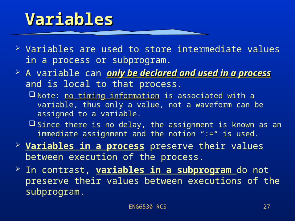
Variables are used to store intermediate values in a process or subprogram.
A variable can only be declared and used in a only be declared and used in a processprocess and is local to that process. Note: no timing informationno timing information is associated with a variable, thus
only a value, not a waveform can be assigned to a variable. Since there is no delay, the assignment is known as an
immediate assignment and the notion “:=“ is used. Variables in a process preserve their values
between execution of the process. In contrast, variables in a subprogram do not
preserve their values between executions of the subprogram.
ENG6530 RCS 28
TypeType
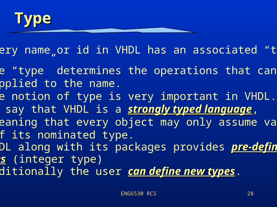
• Every name or id in VHDL has an associated “type”.
• The “type” determines the operations that can be applied to the name.• The notion of type is very important in VHDL.• We say that VHDL is a strongly typed languagestrongly typed language, meaning that every object may only assume values of its nominated type.• VHDL along with its packages provides pre-defined pre-defined typestypes (integer type)• Additionally the user can define new typescan define new types.
ENG6530 RCS 29
User defined typeUser defined type
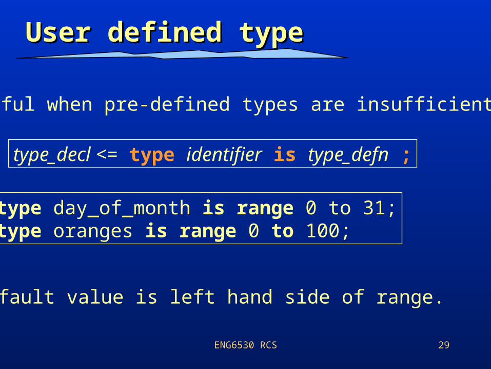
type_decl <= type identifier is type_defn ;
• Useful when pre-defined types are insufficient.
type day_of_month is range 0 to 31;type oranges is range 0 to 100;
• Default value is left hand side of range.
ENG6530 RCS 30
Enumerated typesEnumerated types
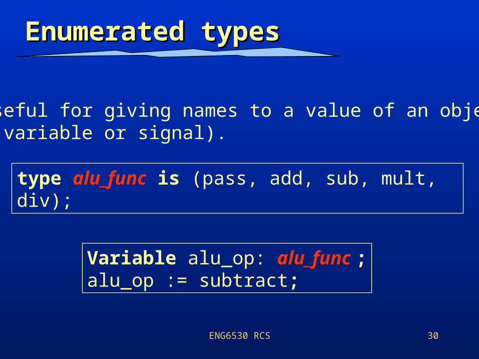
• Useful for giving names to a value of an object (variable or signal).
type alu_func is (pass, add, sub, mult, div);
Variable alu_op: alu_func ;alu_op := subtract;
ENG6530 RCS 31
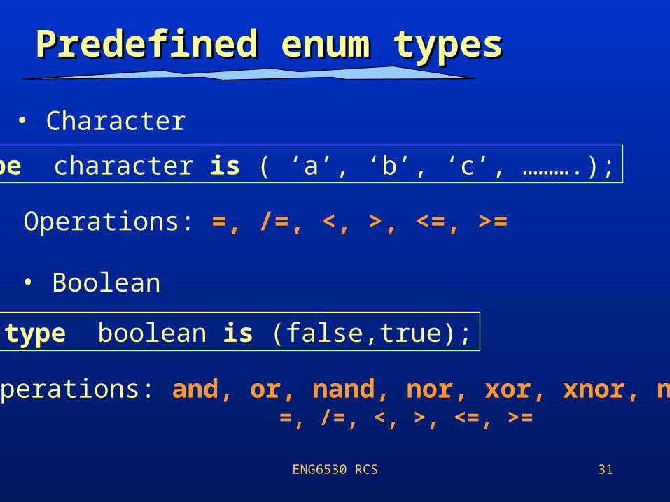
Predefined enum typesPredefined enum types
• Character
type character is ( ‘a’, ‘b’, ‘c’, ……….);
Operations: =, /=, <, >, <=, >=
• Boolean
type boolean is (false,true);
Operations: and, or, nand, nor, xor, xnor, not, =, /=, <, >, <=, >=
ENG6530 RCS 32
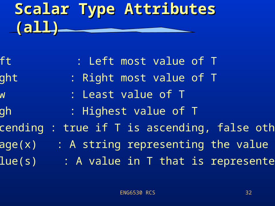
Scalar Type Attributes Scalar Type Attributes (all)(all)
• T’left : Left most value of T
• T’right : Right most value of T
• T’low : Least value of T
• T’high : Highest value of T
• T’ascending : true if T is ascending, false otherwise
• T’image(x) : A string representing the value of x
• T’value(s) : A value in T that is represented by s.
ENG6530 RCS 33
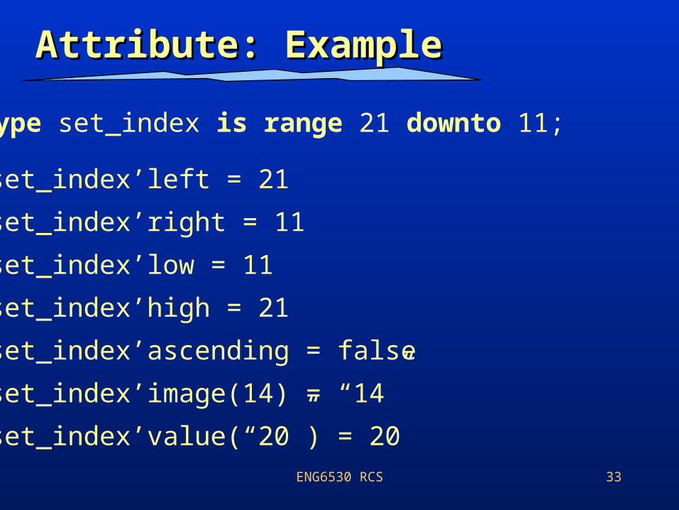
Attribute: ExampleAttribute: Example
type set_index is range 21 downto 11;
set_index’left = 21
set_index’right = 11
set_index’low = 11
set_index’high = 21
set_index’ascending = false
set_index’image(14) = “14”
set_index’value(“20”) = 20
ENG6530 RCS 34
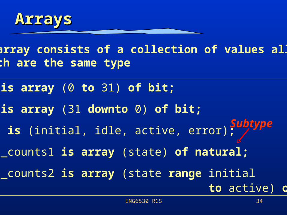
ArraysArrays
type word is array (0 to 31) of bit;
type word is array (31 downto 0) of bit;
type state is (initial, idle, active, error);
type state_counts1 is array (state) of natural;
type state_counts2 is array (state range initial to active) of natural;
An array consists of a collection of values all ofWhich are the same type
Subtype
ENG6530 RCS 35
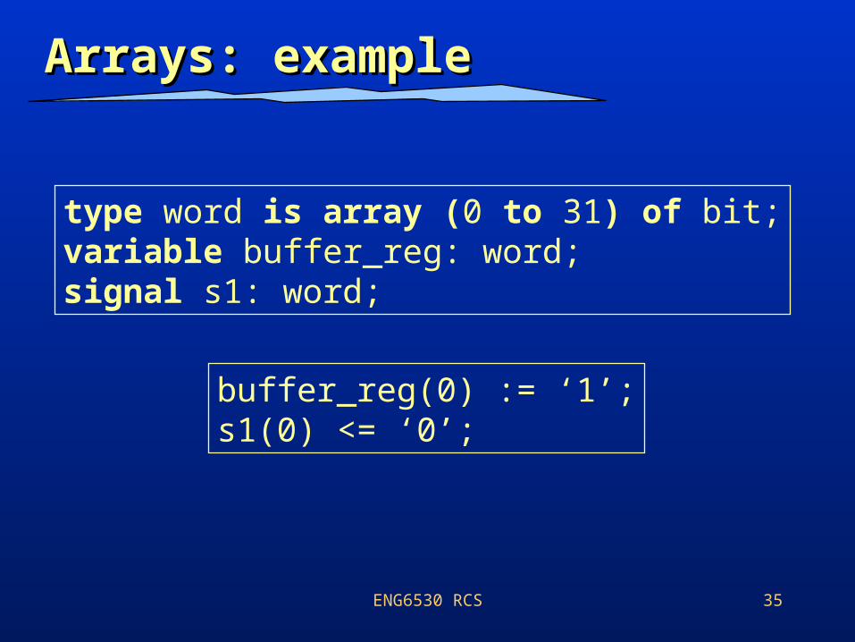
Arrays: exampleArrays: example
type word is array (0 to 31) of bit;variable buffer_reg: word;signal s1: word;
buffer_reg(0) := ‘1’;s1(0) <= ‘0’;
ENG6530 RCS 36
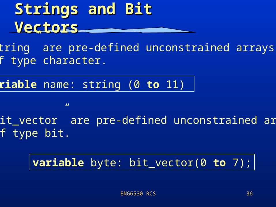
Strings and Bit VectorsStrings and Bit Vectors
• “string” are pre-defined unconstrained arrays of type character.
variable name: string (0 to 11)
• “bit_vector” are pre-defined unconstrained arrays of type bit.
variable byte: bit_vector(0 to 7);
ENG6530 RCS 37
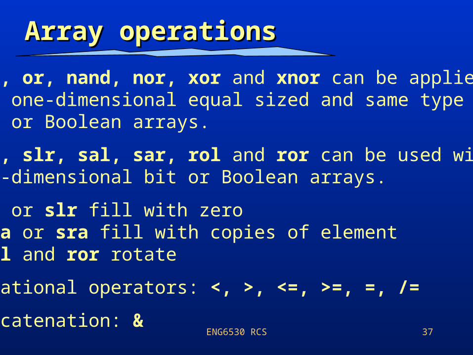
Array operationsArray operations
• and, or, nand, nor, xor and xnor can be applied two one-dimensional equal sized and same type bit or Boolean arrays.
• sll, slr, sal, sar, rol and ror can be used with one-dimensional bit or Boolean arrays.
• sll or slr fill with zero sla or sra fill with copies of element rol and ror rotate
• Relational operators: <, >, <=, >=, =, /=
• Concatenation: &
ENG6530 RCS 38
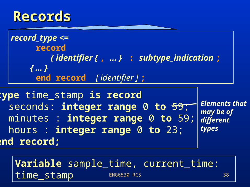
RecordsRecordsrecord_type <= record ( identifier { , … } : subtype_indication ; { … } end record [ identifier ] ;
type time_stamp is recordseconds: integer range 0 to 59;minutes : integer range 0 to 59;hours : integer range 0 to 23;
end record;
Elements that may be of different types
Variable sample_time, current_time: time_stamp
ENG6530 RCS 39
Generics Generate Statements
ENG6530 RCS 40
Generics: MotivationsGenerics: Motivations
Oftentimes we want to be able to specify a property separately for each instance of a component.
VHDL allows models to be parameterized with generics.
Allows one to make general models instead of making specific models for many different configurations of inputs, outputs, and timing information.
Information passed into a design description from its environment.
ENG6530 RCS 41
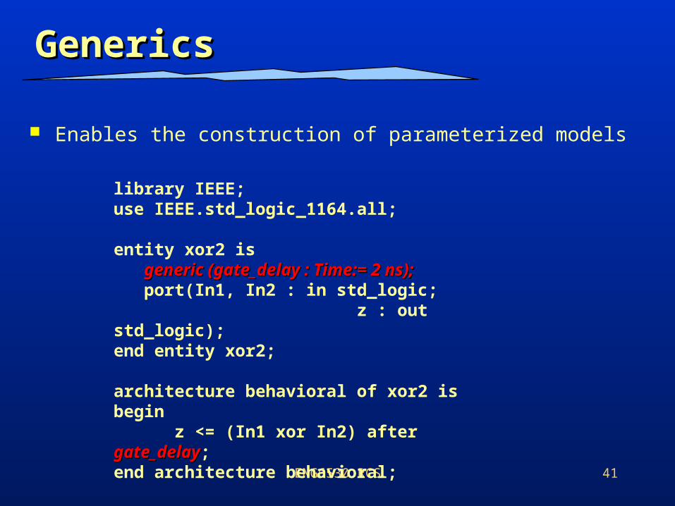
Generics Generics
Enables the construction of parameterized models
library IEEE;use IEEE.std_logic_1164.all;
entity xor2 is generic (gate_delay : Time:= 2 ns);generic (gate_delay : Time:= 2 ns); port(In1, In2 : in std_logic; z : out std_logic);end entity xor2;
architecture behavioral of xor2 isbegin z <= (In1 xor In2) after gate_delaygate_delay;end architecture behavioral;
ENG6530 RCS 42
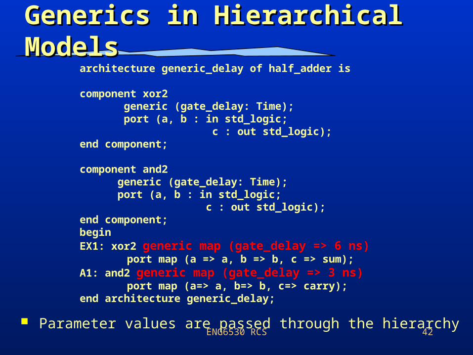
Generics in Hierarchical Generics in Hierarchical ModelsModels
Parameter values are passed through the hierarchy
architecture generic_delay of half_adder is
component xor2 generic (gate_delay: Time); port (a, b : in std_logic; c : out std_logic);end component;
component and2 generic (gate_delay: Time); port (a, b : in std_logic; c : out std_logic);end component;beginEX1: xor2 generic map (gate_delay => 6 ns)
port map (a => a, b => b, c => sum);A1: and2 generic map (gate_delay => 3 ns)
port map (a=> a, b=> b, c=> carry);end architecture generic_delay;
ENG6530 RCS 43
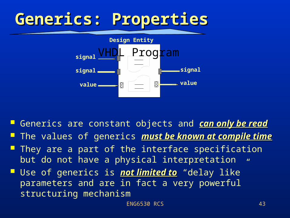
Generics: PropertiesGenerics: Properties
signal
signal
value
signal
VHDL Program
value
Design Entity
Generics are constant objects and can only be readcan only be read The values of generics must be known at compile timemust be known at compile time They are a part of the interface specification but do not
have a physical interpretation Use of generics is not limited tonot limited to “delay like” parameters
and are in fact a very powerful structuring mechanism
ENG6530 RCS 44
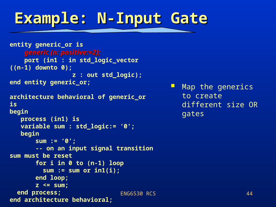
Example: N-Input GateExample: N-Input Gate
Map the generics to create different size OR gates
entity generic_or is generic (n: positive:=2);generic (n: positive:=2); port (in1 : in std_logic_vector ((n-1) downto 0); z : out std_logic);end entity generic_or;
architecture behavioral of generic_or isbegin process (in1) is variable sum : std_logic:= ‘0’; begin sum := ‘0’; -- on an input signal transition sum must be reset for i in 0 to (n-1) loop sum := sum or in1(i); end loop; z <= sum; end process;end architecture behavioral;
45
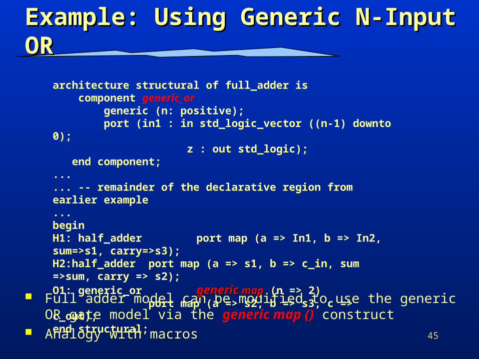
Example: Using Generic N-Input Example: Using Generic N-Input OR OR
Full adder model can be modified to use the generic OR gate model via the generic map () construct
Analogy with macros
architecture structural of full_adder is component generic_or generic (n: positive); port (in1 : in std_logic_vector ((n-1) downto 0); z : out std_logic); end component;...... -- remainder of the declarative region from earlier example...beginH1: half_adder port map (a => In1, b => In2, sum=>s1, carry=>s3);H2:half_adder port map (a => s1, b => c_in, sum =>sum, carry => s2);O1: generic_or genericgeneric mapmap (n => 2)
port map (a => s2, b => s3, c => c_out);end structural;
ENG6530 RCS 46
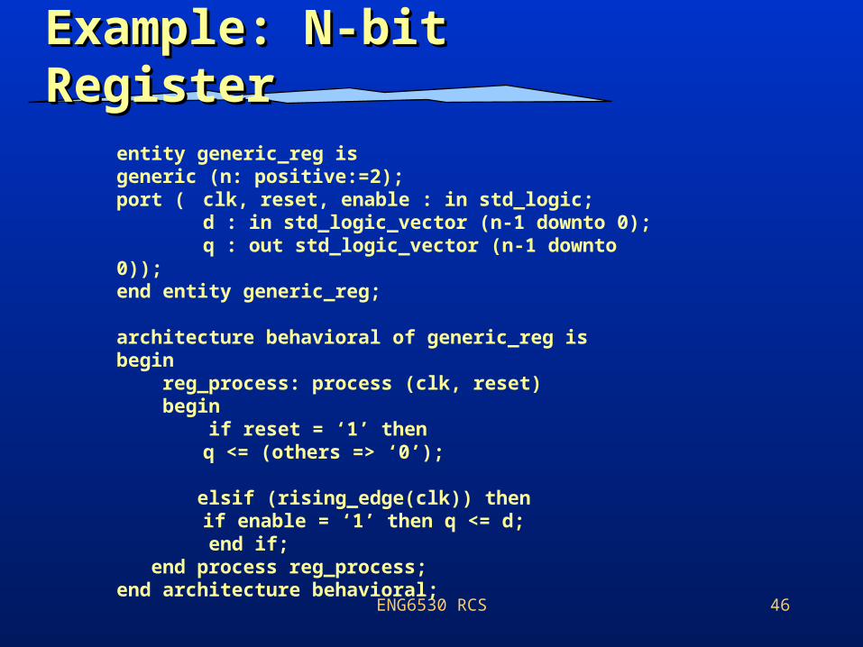
Example: N-bit RegisterExample: N-bit Register
entity generic_reg isgeneric (n: positive:=2);port ( clk, reset, enable : in std_logic;
d : in std_logic_vector (n-1 downto 0);q : out std_logic_vector (n-1 downto 0));
end entity generic_reg;
architecture behavioral of generic_reg isbegin reg_process: process (clk, reset) begin if reset = ‘1’ then
q <= (others => ‘0’); elsif (rising_edge(clk)) then
if enable = ‘1’ then q <= d; end if; end process reg_process;end architecture behavioral;
ENG6530 RCS 47
The Generate The Generate StatementStatement
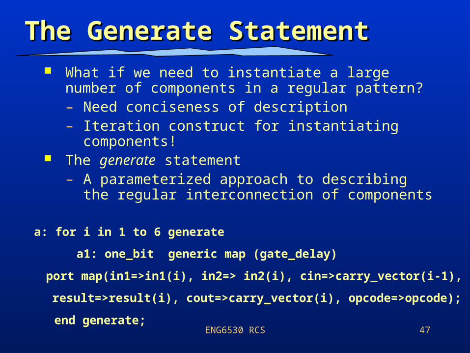
What if we need to instantiate a large number of components in a regular pattern?– Need conciseness of description– Iteration construct for instantiating
components! The generate statement
– A parameterized approach to describing the regular interconnection of components
a: for i in 1 to 6 generate
a1: one_bit generic map (gate_delay)
port map(in1=>in1(i), in2=> in2(i), cin=>carry_vector(i-1),
result=>result(i), cout=>carry_vector(i), opcode=>opcode);
end generate;
ENG6530 RCS 48
Generate Statement: Generate Statement: ExampleExample
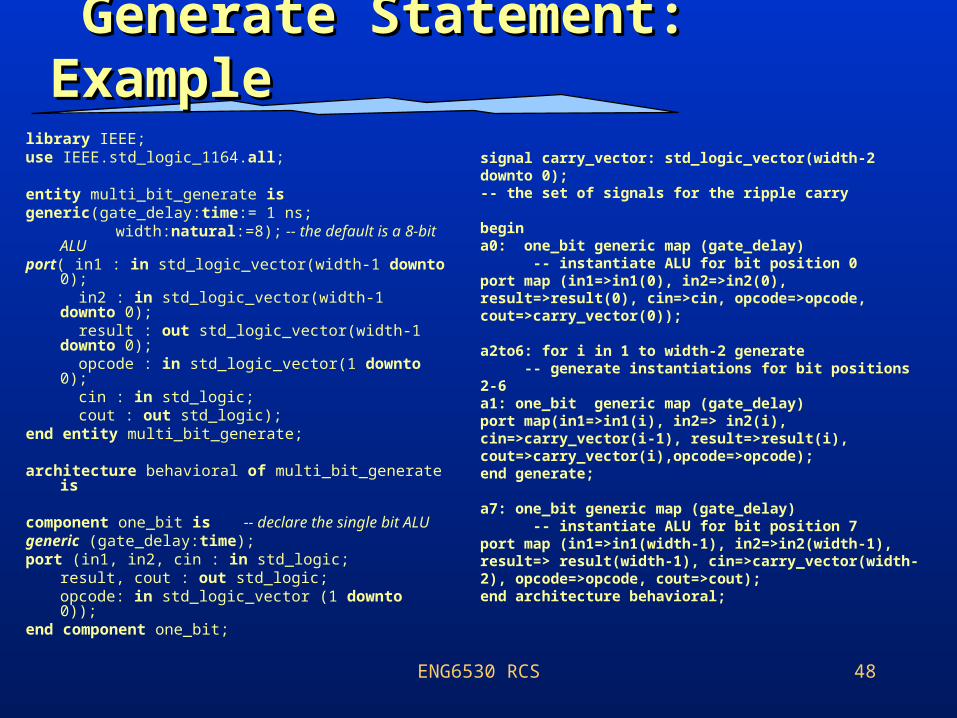
library IEEE;use IEEE.std_logic_1164.all;
entity multi_bit_generate is generic(gate_delay:time:= 1 ns;
width:natural:=8); -- the default is a 8-bit ALU
port( in1 : in std_logic_vector(width-1 downto 0); in2 : in std_logic_vector(width-1 downto 0); result : out std_logic_vector(width-1 downto 0); opcode : in std_logic_vector(1 downto 0); cin : in std_logic; cout : out std_logic);
end entity multi_bit_generate;
architecture behavioral of multi_bit_generate is
component one_bit is -- declare the single bit ALU
generic (gate_delay:time);port (in1, in2, cin : in std_logic;
result, cout : out std_logic;opcode: in std_logic_vector (1 downto 0));
end component one_bit;
signal carry_vector: std_logic_vector(width-2 downto 0); -- the set of signals for the ripple carry
begina0: one_bit generic map (gate_delay) -- instantiate ALU for bit position 0 port map (in1=>in1(0), in2=>in2(0), result=>result(0), cin=>cin, opcode=>opcode, cout=>carry_vector(0));
a2to6: for i in 1 to width-2 generate -- generate instantiations for bit positions 2-6a1: one_bit generic map (gate_delay)port map(in1=>in1(i), in2=> in2(i), cin=>carry_vector(i-1), result=>result(i), cout=>carry_vector(i),opcode=>opcode);end generate;
a7: one_bit generic map (gate_delay) -- instantiate ALU for bit position 7port map (in1=>in1(width-1), in2=>in2(width-1), result=> result(width-1), cin=>carry_vector(width-2), opcode=>opcode, cout=>cout);end architecture behavioral;
ENG6530 RCS 49
ProceduresProcedures FunctionsFunctions
ENG6530 RCS 50
Subprograms: Subprograms: MotivationMotivation
• Often the algorithmic model becomes so large that it needs to be split in to distinct code segments.
• Sometimes a set of statements need to be executed over and over again in different parts of the model.
• Splitting the model into subprogramsSplitting the model into subprograms is a programming practice that addresses the above mentioned issues (i.e., Complexity)
ENG6530 RCS 51
Procedures and Procedures and FunctionsFunctions
• VHDL provides two sub-program constructs:
• Procedure : generalization for a set of statements.
• Function : generalization for an expression.
• Both procedures and functions have an interface specification and body specification.
ENG6530 RCS 52
Declaration of Declaration of Procedures and Procedures and FunctionsFunctions
• Both procedure and functions can be declared in the declarative parts of:
• Process
• Package interface
• Other procedures and functions
• Architecture
ENG6530 RCS 53
Function: ExampleFunction: Example
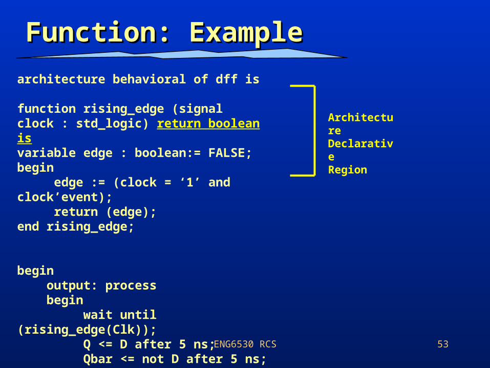
architecture behavioral of dff is
function rising_edge (signal clock : std_logic) return boolean isvariable edge : boolean:= FALSE;begin edge := (clock = ‘1’ and clock’event); return (edge);end rising_edge;
begin output: process begin wait until (rising_edge(Clk)); Q <= D after 5 ns; Qbar <= not D after 5 ns; end process output;end architecture behavioral;
ArchitectureDeclarativeRegion
ENG6530 RCS 54
Placement of FunctionsPlacement of Functions
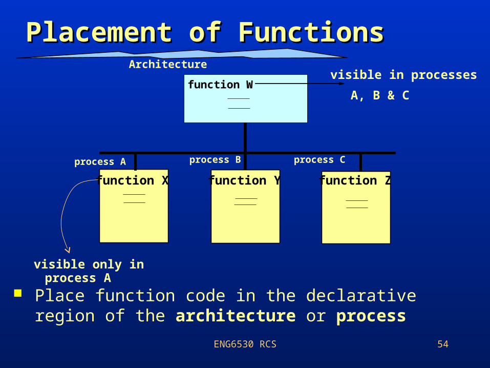
Place function code in the declarative region of the architecture or process
process A process B process C
function X function Y function Z
function W
Architecturevisible in processes
A, B & C
visible only inprocess A
ENG6530 RCS 55
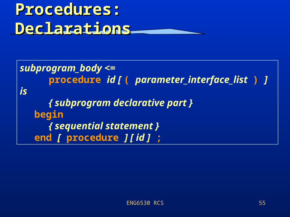
Procedures: Procedures: DeclarationsDeclarations
subprogram_body <= procedure id [ ( parameter_interface_list ) ] is
{ subprogram declarative part }begin
{ sequential statement }end [ procedure ] [ id ] ;
ENG6530 RCS 56
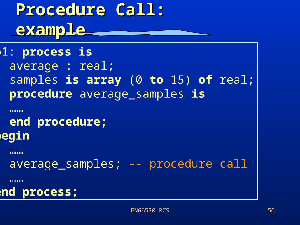
Procedure Call: Procedure Call: exampleexamplep1: process is
average : real;samples is array (0 to 15) of real;procedure average_samples is……end procedure;
begin……average_samples; -- procedure call……
end process;
ENG6530 RCS 57
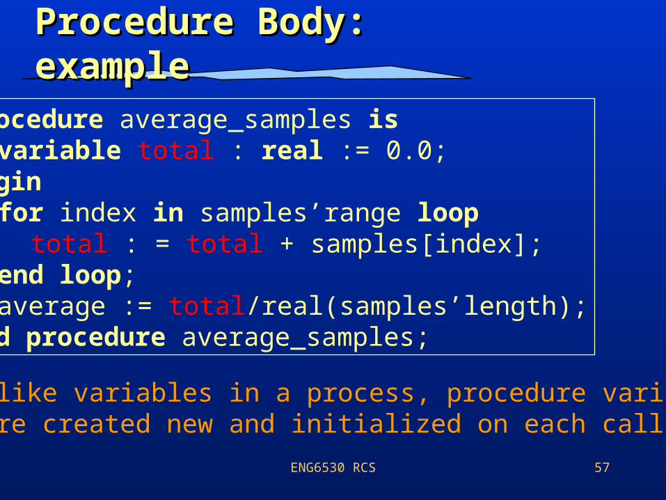
Procedure Body: Procedure Body: exampleexample
procedure average_samples isvariable total : real := 0.0;
beginfor index in samples’range loop
total : = total + samples[index];end loop;average := total/real(samples’length);
end procedure average_samples;
• Unlike variables in a process, procedure variables are created new and initialized on each call.
ENG6530 RCS 58
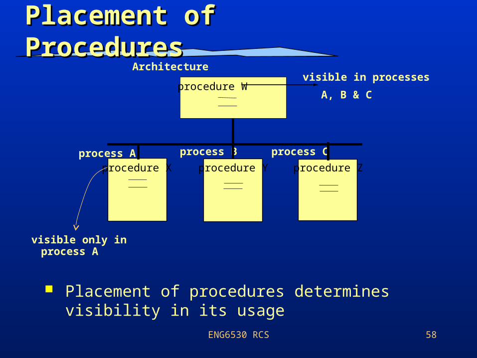
Placement of Placement of ProceduresProcedures
Placement of procedures determines visibility in its usage
process A process B process C
procedure X procedure Y procedure Z
procedure W
Architecturevisible in processes
A, B & C
visible only inprocess A
ENG6530 RCS 59
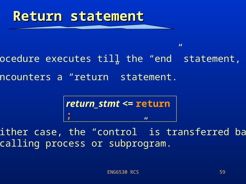
Return statementReturn statement
• A procedure executes till the “end” statement, OR
• It encounters a “return” statement.
• In either case, the “control” is transferred back to the calling process or subprogram.
return_stmt <= return ;
ENG6530 RCS 60
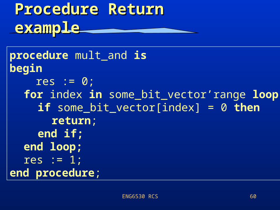
Procedure Return Procedure Return exampleexample
procedure mult_and isbegin res := 0;
for index in some_bit_vector’range loopif some_bit_vector[index] = 0 then
return;end if;
end loop;res := 1;
end procedure;
ENG6530 RCS 61