
of Relevant MDL 2179 Docket Entries Relating to Economic and ...
Recommended Practices forBlowout Prevention EquipmentSystems for Drilling Wells
API RECOMMENDED PRACTICE 53
THIRD EDITION MARCH 1997
REAFFIRMED SEPTEMBER 2004
eneyCopyjightAmericail Petroleum Institute
Provided by il-IS viaderilvenar jAb PAt Spid IsSAT GONSULTINIG P15909502
No ropcodocov or neiwocklop poraritted without trance born INS Nat tortraauio201QG/1b 164455 GM7
PSC-MDL21 79-011038

Oopyolglit AmerFcan Petroleum Institute
rmetdod by IllS under licence with API Sold tcSST CONSULTING W3u0u362Cu reproduction onnoiwcrkmnperedttrd withoutliouncu truer li-lu Nut Icr ReneleZOlnirtlu 16446 CMT
PSC-MDL21 79-011039
Copyright Alrerfcan Pelroleum Instl1ute Provldad by I{iS vndar Ilcenu wilh AP' No r~produollon or IlOtworkln9 permitted wlthout lloense from IHS
Sold to;8& T CONSULTING. woe09362 Not for ReealE!,2'Ol015/18 16:44:~B GMT
PSC-MDL2179-011039
Recommended Practices for
Blowout Prevention EquipmentSystems for Drilling Wells
Exploration and Production Department
API RECOMMENDED PRACTICE 53
THIRD EDITION MARCH 1997
REAFFIRMED SEPTEMBER 2004
enerf
CopyrlplilAtoedoan Petroleum Inelitulu
Provided by IAN ueidec license with API Sold toOT CONOULTINGOo9362No reproduction or networking permitted without license hoer Il-IS Not for Reoole201015lf tS44w6 GMT
PSC-MDL21 79-011040

SPECIAL NOTES
API publications necessarily address problems of general nature With respect to partic
ular circumstances local state and federal laws and regulations should be reviewed
API is not undertaking to meet the duties of employers manufacturers or suppliers to
warn and properly train and equip their employees and others exposed concerning health
and safety risks and precautions nor undertaking their obligations under local state or fed
eral laws
Information concerning safety and health risks and proper precautions with respect to par
ticular materials and conditions should be obtained from the employer the manufacturer or
supplier of that material or the material safety data sheet
Nothing contained in any API publication is to be construed as granting any right by
implication or otherwise for the manufacturer sale or use of any method apparatus or
product covered by letters patent Neither should anything contained in the publication be
construed as insuring anyone against liabilityfor infringement of letters patent
Generally API standards are reviewed and revised reaffirmed or withdrawn at least every
five years Sometimes one-time extension ofup to two years will be added to this review
cycle This publication will no longer be in effect five years after its publication date ns an
operative API standard or where an extension has been granted upon republication Status
of the publication can be ascertained from the API Exploration Production Department1220 Street NW Washington DC 20005 catalog of API publications and materials is
published annually and updated quarterly by API 1220 Street N.W Washington D.C20005
This document was produced under API standardization procedures that ensure appropri
ate notification and participation in the developmental process and is designated as an API
standard Questions concerning the interpretation of the content of this staadard or comments and questions concerning the procedures under which this standani was developed
should be directed in writing to the director of the Authoring Department shown on the title
page of this document American Petroleum Institute 1220 Street NW Washington
D.C 20005 Requests for permission to reproduce or translate all or any part of the material
published herein should also be addressed to the director
APT standards are published to facilitate the broadavailability of proven sound engineer
ing and operating practices Theso standards are not intended to obviate the need for apply
ing sound engineering judgment regarding when and where these standards should be
utilized The formulation and publication of API standards is not intended in any way to
inhibit anyone from using any other practices
Any manufacturer marking equipment or materials in conformance with the marking
requirements of an API standard is solely responsible for complying with all the applicable
requirements of that standard API does not represent warrant or guarantee that such products do in fact conform to the applicable API standattl
MI rights reserved No part of this work may be repmduce4 stored in retrieval system or
transmitted by any means electmnic mechanical photocopying recording or otherwise
withour prior written permission from the publisher Cot ttact the Publisher
API Publishing Services 1220 Street Washington D.C 20005
Copyright I997Amerioan Pettuictun trtstitute
Copyright America Piroimim Iritut
Pcvldedby iF under Rcane with API mold toST CONStJLTlido W0900362Norproduodon or noiwordlog pororillod wilIrot horn rrm IHS idol fur Redm2OlQC/i8 151456 CMI
PSC-MDL21 79-011041

FOREWORD
These recommended practices were prepared by the API Subcommittee on Blowout Pre
vention Equipment Systems They represent composite of the practices employed by vari
ous operating and drilling companies indrilling operations In some cases reconciled
composite of the various practices employed by these companies was utilized This publica
tion is under the jurisdiction of the American Petroleum Institute Exploration Production
Departments Executive Committee on Drilling and Production Practices
API Recommended Practice 53 First Edition February 1976 superseded and replaced
API Bulletin D13 Installation and Use of Blowout Preventer Stacks and Accessory Equip
ment February 1966 The Second Edition was issued in May 1984
Drilling operations are being conducted with full regard for personnel safety public
safety and preservation of the environment in such diverse conditions as metropolitan sites
wilderness areas ocean platforms deep water sites barren deserts wildlife refuges and arc
tic ice packs Recommendations presented in this publication are based on this extensive and
wide ranging industry experience
The goal of these voluntary recommended practices is to assist the oil and gas industry in
promoting personnel safety public safety integrity of the drilling equipment and preservation of the environment for land and marine drilling operations These recommended praotices are published to facilitate the broad
availabilityof proven sound engineering and
operating practices This publication does not present all of the operating practices that can
be employed to successfully install and operate blowout preventer systems in drilling operations Practices set forth herein are considered acceptable for accomplishing the job as
described however equivalent alternative installations and practices may be utilized to
accomplish the same objectives Individuals and organizations using these recommended
practices are cautioned that operations must comply with requirements of federal state or
local regulations These requirements should be reviewed to determine whether violations
may occur
The formulation and publication of API recommended practices is not intended in any
way to inhibit anyone from using other practices Every effort has been made by API to
assure the accuracy and reliability of data contained in this publication However the Insti
tute makes no representation warranty or guarantee in connection with publication of these
recommended practices and hereby expressly disclaims any liability or responsibility for
loss or damage resulting from use or applications hereunder or for violation of any federal
state or local regulations with which the contents may conflict
Users of recommendations set forth herein are reminded that constantly developing tech
nology and specialized or limited operations do not permit complete coverage of all opera
tions and alternatives Recommendations presented herein arc not intended to inhibit
developing technology and equipment improvements or improved operating procedures
These recommended practices are not intended to obviate the need for qualified engineering
and operations analyses and sound judgments as to when and where these recommended
practices shoutd be utilized to fit specific drilling application
This publication includes use of the verbs shall and should whichever is deemed the most
applicable for the specific situation For the purposes of this publication the following defi
nitions are applicable
Shall Indicates that the recommended practices has universal applicability to that specific activity
Should Denotes recommended practices where safe comparable alternative
practices is available that may be impractical under certain circumstances ore that
may be unnecessary under certain circumstances or applications
Changes in the uses of these verbs are not to be effected without risk of changing the
intent of rccommendations set forth herein
CopydghtAnedcun Potrouuni InuSlulu
Provided byIHS under lluvnuowNn APi anSi lo551 CONSIJLT1NGWDnnnSe2No repredoudon or neiwuriluru perrnsnd without flounce Iono Ha Not fur Nuele.ZtlQltflt l544dA CMT
PSC-MDL21 79-011042
API publications may be used by anyone desiring to do so Every effort has been made by
the Institute to assure the accuracy andreliability
of the data contained in them however the
Institute makes no representation warranty or guarantee in connection with this publication
and hereby expressly disclaims any liability or responsihility for loss or damage resulting
from its use or for the violation of any federal state or municipal regulation with which this
publication may conflict
Suggestions for revisions or additions are invited and should be submitted to the Director
Exploration and Production Department American Petroleum Institute 1220 Street NWWashington DC 20005
Iv
Copyrhourl American poiroleLim hiiellIuto
ProvIded by lAm under Ileerme mliii API Sold loST COIISIJLTIIIO Wouosfes
Noenproducllen or netemrlriny perollied orinhoer Ileenne from HA Hot for Aeoeir2OlO/518 54456 GMT
PSC-MDL21 79-011043
CONTENTS
Page
SCOPE1.1 Purpose
1.2 WeilControl
1.3 SOP Installations
1.4 Equipment Arrangements
1.5 Low Temperature Operations
1.6 In-the-field Control System Accumulator Capacity
REFERENCES
2.1 Standards
2.2 Other References
DEFINITIONS AND ABBREVIATIONS
3.1 Definitions
3.2 Acronyms and Abbreviations
DIVERTER SYSTEMSSURFACE BOP INSTALLATIONS
41 Purpose
4.2 Equipment and Installation Guidelines
DIVBRTER SYSTEMSSUBSEA SOP INSTALLATIONS
5.1 Purpose
5.2 Equipment and Installation Guidelines
SURFACE BOP STACK ARRANGEMENTS6.1 Example BOP Stack Arrangements
6.2 Stack Component Codes
6.3 Ram Locks
6.4 Spare Parts
6.5 Parts Storage
6.6 Drilling Spoois
SUB SEA SOP STACK ARRANGEMENTS7.1 Example BOP Stack Arrangements
7.2 Stack Component Codes 13
7.3 Subsea BOP StackArrangements 13
74 Spare Parts 13
7.5 Parts Storage 13
7.6 Drilling Spools 13
CHOKE MANIFOLDS AND CHOKE LINESSURFACE flOP
INSTALLATIONS 14
8.1 General 14
8.2 Installation GuidelinesChoke Manifold 14
8.3 Installation GuidelinesChoke Lines 14
8.4 Maintenance 15
8.5 Spare Parts 17
CopyrtghlAmodcsn Petroleum minute
Provided by li-IS under license with APt Sold lorSST CONSULTING W0900362
i-ic raprodu050n or nelvrorklrg ponelilodseitheul licence from illS Net or Rosoio2010t0le 16r445$ GMT
PSC-MDL21 79-011044
Page
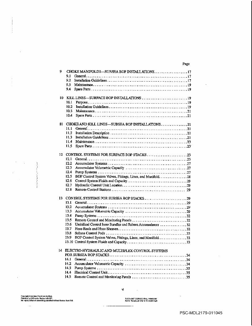
CHOKE MANIFOLDSSUBSBA BOY INSTALLATIONS 17
9.1 General 17
92 Installation Guidelines 17
9.3 Maintenance 19
94 SpareParts 19
10 KILL LINESSURFACE BOY INSTALLATIONS 19
10.1 Purpose 19
10.2 Installation Guidelines 19
10.3 Maintenance 21
10.4 SpareParts 21
11 CHOKE AND KILL LINESSUBSEA flOP INSTALLATIONS 21
11.1 General 21
11.2 Installation Description 21
11.3 Installation Guidelines
11.4 Maintenance 23
11.5 Spare Parts 23
12 CONTROL SYSTEMS FOR SURFACE BOY STACKS 23
12.1 General 23
122 Accumulator Systems 27
12.3 AceumulatorVolumetdc Capacity 27
12.4 Pump Systems 27
12.5 BOY Control System Valves Fittings Lines and Manifold 28
12.6 Coatrol System Fluids andCapacity 29
12.7 Hydraulic Control Unit Location 29
12.8 Remote Control Stations 29
13 CONTROL SYSTEMS FOR SUBSEA flOP STACKS 29
13.1 General 29
132 Accumulator Systems 29
13.3 Accumulator Volumetric Capacity 29
13.4 Pump Systems 32
135 Remote Control and Monitoring Panels 32
13.6 Umbilical Control hose Bundles and Subsea Accumulators 32
137 Hose Reels and Hose Sheaves 32
13.8 Subsea Control Pods 33
119 flOP Control System Valves Fittings Lines and Manifold 33
13.10 Control System Fluids and Capacity 33
14 ELECTRO-HYDRAULIC AND MULTIPLEX CONTROL SYSTEMSFOR SUBSEA BOP STACKS 34
14.1 General 34
14.2 Accumulator Volumetric Capacity 34
14.3 Pump Systems 35
14.4 Electrical Control Unit 35
14.5 Remote Control and Monitoring Panels 35
VI
Copyright American Petroleum iroutituto
Pm4dud by li-IS order lironeeudih APt Sold imS-I CONSULTING t55901362
No reprortrjrliop erneiworking permitted rdUrtui ileerrue from INS Not for Reuate2Ol0IfrJlS 164456 CMI
PSC-MDL21 79-011045

Page
14.6 Subsea Umbilical Cables and Connectors 35
14.7 Subsea Electrical Equipment 36
15 AUXILIARY EQUIPMENTSURFACE BOP INSTALLATIONS 36
15.1 KellyValves 36
152 Drill Pipe Safety Valve 36
15.3 Inside BlowoutPreventer 36
15.4 FieldTesting 36
15.5 Drill String Float Valve 36
15.6 Trip Tank 36
15.7 Pit Volume Measuring and Recording Devices 37
15.8 flow Rate Sensor 37
15.9 Mud/Gas Separator 37
15.10 Degasser 37
15.11 PlareLines 37
15.12 Stand PipeChoke 37
15.13 Top DriveEquipment 38
16 AUXiLIARY EQUIPMENTSIJBSBA BOP INSTALLATIONS 38
16.1 Kelly Valves 38
162 Drill Pipe Safety Valve 38
16.3 Inside Blowout Preventer 38
16.4 Field Testing 38
16.5 Drill String Float Valve 38
16.6 TripTank 38
16.7 Pit Volume Measuring and Recording Devices 39
16.8 flow Rate Sensor 39
16.9 Mud/Gas Separator 39
16.10 Degasser 39
16.11 FlareLines 39
16.12 Stand PipeChoke 39
16.13 TopDriveEquipment 39
16.14 Guide Frames 39
16.15 Underwater Thlevision 40
16.16 Slope Indicator 40
16.17 Pin Connectorfflydraulic Latch 40
16.18 Mud Booster Line 40
16.19 Auxiliary Hydraulic Supply Line Hard/Rigid Conduit 40
16.20 Riser Tensioning Support Ring 40
17 TESTING AND MAINTENANCESURFACE BOP STACKS ANDWELL CONThOL EQUIPMENT 40
171 Purpose 40
17.2 Irpes of Tests 40
17.3 Test Criteria 41
17.4 DiverterSysteni 45
17.5 Surtace BOP Stack Equipment 45
17.6 Chokes and Choke Manifolds 46
17.7 Accumulator System 46
vU
Copyriuhi American Pebolaum Inolibde
Provided by HG under Ivonoy cnilb API Sold toST CONSULTING h4un93u2
Norepruuluuflur or notwurbing yormilled wiliroul licence Poor INS Nd Icr Oeauie20n016110 nO44r5u GMT
PSC-MDL21 79-011046

Page
17.8 Auxiliary Equipment 46
17.9 Mud/Gas Separator 46
17.10 Inspections 46
17.11 Maintenance 47
1712 Quality Management 48
17.13 Records and Documentation 48
18 TESTING AND MAINTENANCESUBSEA BOP STACKS AND WELLCONTROL EQUIPMENT 48
18.1 Purpose 43
18.2 Types of Tests 48
18.3 TestCriteria 50
18.4 Diverter System 52
185 Subsea BOP Stack Equipment 55
18.6 Chokes and Choke Manifolds 55
18.7 Accumulator System 55
18.8 Auxiliary Equipment 56
18.9 Mud/Gas Separator 56
18.10 Inspections 56
18.11 Maintenance 56
18.12 Quality Management 57
18.13 Records and Documentation 58
19 flOP SEALING COMPONENTS 58
19.1 Flangesand Hubs 58
19.2 EquipmentMarking 58
19.3 Ring-joint Gaskets 58
19.4 Bolting 58
19.5 Elastomeric Components 60
19.6 Elastomeric Compo cents for Hydrogen Sulfide Service 60
19.7 Integral Choke and Kill Lines 60
19.8 Subsea Wellhead Connector 60
19.9 Marine Riser 60
19.10 Subsea Control System 60
20 BLOWOUT PREVENTERS FOR HYDROGEN SULFIDE SERVICE 61
20.1 Applicability 61
20.2 Equipment Modifications 61
21 PiPE STRWPING ARRANGEMENTSSURFACE flOP INSTALLATIONS 61
21.1 Purpose 61
21.2 Equipment 61
21.3 Personnel Preparedness 62
214 Surface Equipment 62
21.5 Subsurface Equipment 62
viii
Gopyrluld Aroerloen Petrdeum molIere
Providedtry
11W rodeo Iloerree with API Sold IvST CONSULTING W0909362
Nvveprvdrrrlleo or oelwvrkleg permitted without Ileeeee rero Il-IS NvlIre Role2010l5/Itt I44r56 Owl
PSC-MDL21 79-011047
Page
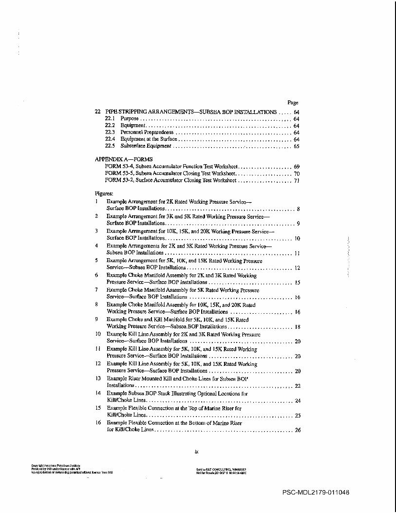
22 PIPE STRIPPING ARRANGEMENTSSUBSEA SOP INSTALLATIONS 64
22.1 Purpose 64
22.2 Equipment 64
22.3 Personnel Preparedness 64
224 Equipment at the Surface 64
22.5 Subsurface Equipment 65
APPENDIX AFORMSFORM 53-4 Subsea Accumulator Function Test Worksheet 69
FORM 53-5 Subsea Accumulator Closing Test Worksheet 70
FORM 53-2 Surface Accumulator Closing Test Worksheet 71
Figures
Example Arrangement for 2K Rated Working Pressure Service
Surface BOP Installations
Example Arrangement for 3K and 5K Rated Working Pressure Service
Surface SOP Installations
Example Arrangement for 10K 15K and 20K Working Pressure Service
Surface SOP Installations 10
Example Anungements for 2K and 3K Rated Working Pressure Service
Subsea SOP Installations 11
Example Arrangement for 5K lOIC and 15K Rated Working Pressure
Service.Subsea SOP Installations 12
Example Choke Manifold Assembly for 2K and 3K Rated Working
Pressure ServiceSurface sop installations 15
Example Choke Manifold Assembly for 5K Rated Working Pressure
ServiceSurface SOP Installations 16
Example Choke Manifold Assembly for 10K 15K and 20K Rated
Working Pressure ServiceSurface SOP Installations 16
Example Choke and Kill Manifold for 5K 10K and 15K Rated
Working Pressure ServiceSubsea BOP Installations 18
10 Example Kill Line Assembly for 2K and 3K Rated Working Pressure
ServiceSurface SOP Installations 20
11 Example Kill Line Assembly for 5K 10K and 15K Rated Working
Pressure ServiceSurface SOP Installations 20
12 Example Kill Line Assembly for 5K 10K and 15K Rated Working
Pressure ServiceSurface SOP Installations 20
13 Example Riser Mounted Kill and Choke Lines for Subsea SOPInstallations 22
14 Example Subsea SOP Stack Illustrating Optional Locations for
Kill/Choke Lines 24
15 Example Flexible Connection at the iop of Marine Riser for
Kill/Choke Lines 25
16 Example Flexible Connection at the Bottom of Marine Riser
for Kill/Choke Lines 26
Copyiqli AnIoo Pelmrnum lrmVltto
Presidedley
lidS undee license with API sold dorSAl COI4SULI1NGWGSOSX2No ecpmdoclion or nntmmklng porrniltedwllhout icertan from ibiS Not for RnoololOlQilFlO l644r5SGMT
PSC-MDL21 79-011048

Page
17 Example Hydraulic Control Schematic for BOP Control System 30
18 Example Standpipe Choke Installations 37
19 Eüxnple IllustratIon of Ram 130 Space Out 49
20 Example Illustration of Rare BOP Space Out 59
21 Example Surface BOP Stack/Choke Manifold Installation 63
Tables
Recommended Pressure Test Practices Land and Bottom-supported
Rigs prior to spud or upon installation 43
Recommended Pressure Test Practices Land and Bottom-supported
Rigs not to esceed 21 days 44
Recommended Pressure Test Practices Floating Rigs with Subsea BOPStacks diverter system prior to spud et al prior to running stack 53
Recommended Pressure Test Practices Floating Rigs with Subsea BOPStacks 130 stack
initially installed on wellhead and not to exceed 21 daysJ .54
Elastomer Compound Marking Code 60
CopyrlobtAmorloon Iolooloom inoiFtol
Provided by I-is ondordcooeo tollS API Nold loN1 CGN0ULTING.W5009362No royrodociloo or notworlllrg pesoItied without Iloenoo from It-IS Not lorP000leZOtOloflO 16r44OSGMT
PSC-MDL21 79-011049

Recommended Practices for Blowout Prevention Equipment Systems for
Drilling Wells
Scope
1.1 PURPOSE
The purpose of these recommended practices is to provide
information that can serve as guide for installation and test
ing of blowout prevention equipment systems on land and
marine drilling rigs barge platform bottom-supported and
floating Elowout prevention equipment systems are com
posed of all systems required to operate the blowout preven
ters SOPs under varying rigand well conditions These
systems art blowout preventers BOPs choke and kill lines
choke manifold hydraulic control system marine riser and
auxiliary equipment The primary functions of these systems
are to confine well fluids to the wellbore provide means to
add fluid to the wellbore and allow controlled volumes to be
withdrawn from the wellbore In addition diverter systems
are addressed in this Recommended Practice though their
primary purpose is to safely divert flow rather than to confine
fluids to the wellbore Refer to API Recommended Practice
64 for additional information on diverter systems Marine ris
ers are not dealt with in detail in this document Refer to API
Recommended Practice 6Q for additional information on
marine drilling risers
1.2 WELLCONTROL
Procedures and techniques for well control are not
included in this publication since they are beyond the scope
of equipment systems contained herein refer to API Recommended Practice 59
1.3 SOP INSTALLATIONS
In some instances this publication contains section per
taining to surface BOP installations followed by section
on subsea BOP installations delineation was made
between snifter and subsect equipment installations so
tk\ese recommended practices would also have utility in
fibating drilling operations Statements concerning surface
equipment installations also generally apply to subsea
eptipment installations
lr.4 EQUIPMENT ARRANGEMENTS
Recommended equipment arrangements as set forth in this
publication are adequate to meet specified well conditions It
is recognized that other arrangements may be equally effec
tive and can be used in meeting well requirements and pro
moting safety and efficiency
CopylelrtAmedoee Petroleum Iretitue
Provided by lHsoedortleveto mith API
No reproductIon oroetworkiog permitted withoot Ileeooe from IHS
1.5 LOW TEMPERATURE OPERATIONS
Although operations are being conducted in areas of
extremely luw temperatures section specifically applicabLe
to this service was not included since current practice gener
ally results in protecting existing flOP equipment from this
environment
1.6 IN-THE-FIELD CONTROL SYSTEM
ACCUMULATOR CAPACITY
It is important to distinguish between the standards for in-
the-field control system accumulator capacity established
herein Recommended Practice 53 and the design standards
established in API Specification 161
API Specification 16D provides sizing guidelines for
designers and manufacturers of control systems In the fac
tory it is not possible to exactly simulate the volumetric
demands of the control system piping hoses fittings valves
flOPs etc On the rig efficiency losses in the operation of
fluid functions result from causes such as friction hose
expansion control valve interflow as well as heat energy
losses Therefore the establishment by the manufacturer of
the design accumulator capacity provides safety factor This
safety factor is margin of additional fluid capacity which is
not actually intended to be usable to operate well control
functions on the rig
For this reason the control system design accumulator
capacity formulas established in Specification 161 are differ
ent from the demonstrable capacity guidelines provided here
in Recommended Practice 53
The original control system manufacturer shall be con
sulted in the event that the field calculations or field testing
should indicate insufficient capacity or in the event that the
volumetric requirements of equipment being controlled are
changed such as by the modification or changeout of the
BOP stack
References
2.1 STANDARDS
The following standards contain provisions which through
reference in this text constitute provisions of this standard
All standards are subject to revision and users are encouraged
tu investigate the possibility of applying the most recent edi
tions of the standards indicated below
Sold teNT CONSULTING W0900352
Netter RoelegolmS18 terdUrfU CMI
PSC-MDL21 79-011050
API RECOMMENDED PRACTICE 53
ASTM
D- 1418 Practice for Rubber and Rubber Lattices
Nomenclature
Material Requirements SuWde Stress Crack
ing Resistant metallic Materials for Oiifield
Equipment
2.2 OTHER REFERENCES
8PE
SPE 20430 Mud Gas Separator Sizing and Evaluation
G.R MacDougall December 1991
SPE 23900 Field Guide for Surface SOP Equipment
Inspections Wi Kandel and D.J Streu
February 1992
American National Standards Institute 1430 Broadway New York NY10018
Amcrican Society of Mechanical Engineers 22 Law Drive Box 2300 Fair
field NJ 07007-2300
-American Society for Testing and Materials 1916 Race Street Philadelphia
PA l9I03
4National Association of Corrosion Engineers NACE International Box
217430 Houston Texas 772 18-8340
Society of Petroleum Engineers P.O ace 833836 Richardson TX 75083-
3836
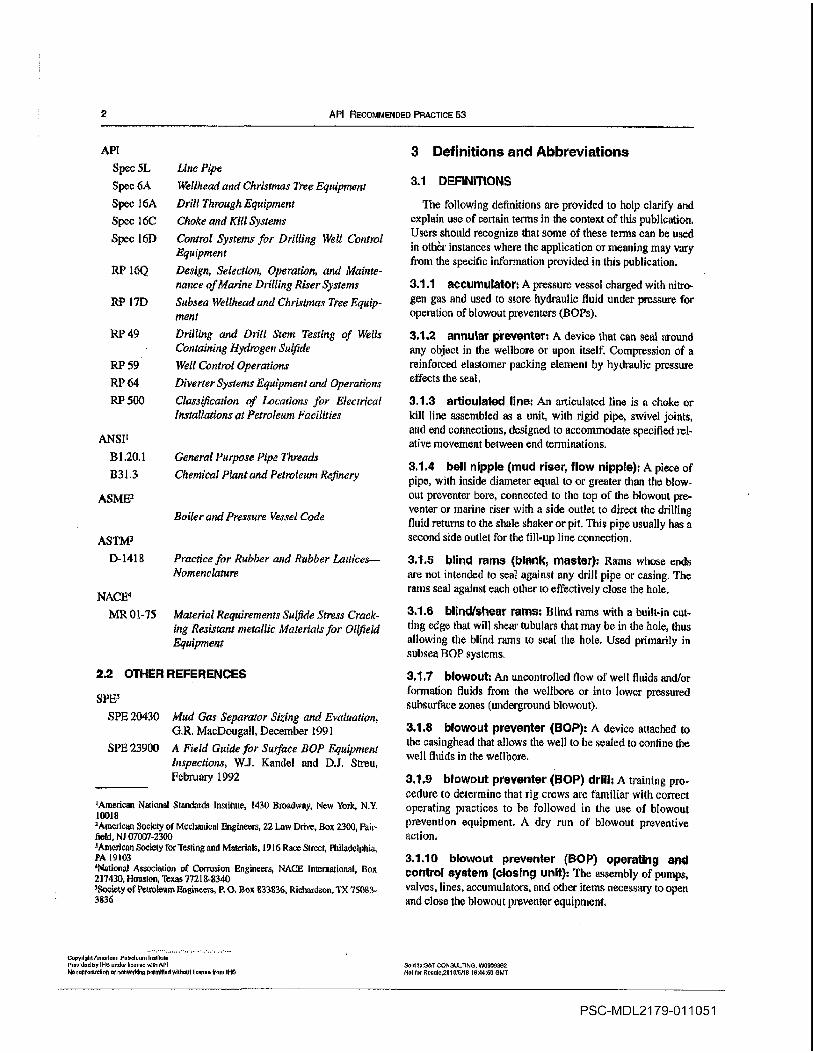
Definitions and Abbreviations
11 DEFINITIONS
The following definitions are provided to help clarify and
explain use of certain terms in the context of this publication
Users should recognize that some of these terms can be used
in other instances where the application or meaning may vary
from the specific information provided in this publication
3.1.1 accumulatort pressure vessel charged with nitro
gen gas and used to store hydraulic fluid under pressure for
operation of blowout preventers BOPs
3.1.2 annular preventer device that can seal around
any object in the wellbore or upon itself Compression of
reinforced elastomer packing element by hydraulic pressure
effects the seal
3.1.3 articulated line An articulated line is choke or
kill line assembled as unit with rigid pipe swivel joints
and end connections designed to accommodate specified rel
ative movement between end terminations
3.1.4 bell nipple mud riser flow nipple piece of
pipe with inside diameter equal to or greater than the blow
out preventer bore connected to tlac top of the blowout pre
venter or marine riser with side outlet to direct the drilling
fluid returns to the shale shaker or pit This pipe usually has
second side outlet for the fill-up line connection
31.5 blind rams blank master Rams whose ends
are not intended to seal against any drill pipe or casing The
rams seal against each other to effectively close the hole
3.1.6 blind/shear rams Blind rams with built-in cut
ting edge that will shear tubulars that may be in the hole thus
allowing the blind rams to seal the hole Used primarily in
subsea flOP systems
3.1.7 blowout An uncontrolled flow of welt fluids and/or
formation fluids from the wellbore or into lower pressured
subsurface zones underground blowout
3.1.8 blowout preventer HOP device attached to
the casinghead that allows the well to be sealed to confine the
well fluids in the wellbore
3.1.9 blowout preventer HOP drill training procedure to determine that rig crews are familiar with correct
operating practices to be followed in the use of blowoul
prevention equipment dry run of blowout preventive
action
3.1.10 blowout preventer HOP Qperating and
control system closing unit The assembly of pumpsvalves lines accumulators and other items necessary to open
and close the blowout preventer equipment
API
Spec SL Line Pipe
Spec 6A WeiThead and Christmas Tme Equipment
Spec IÔA Drill Through Equipment
Spec 6C Choke and Kill Systems
Spec lfiD Contml Systems for Drilling Well Control
Equipment
RP lóQ Design Selection Operation and Mainte
nance of Marine Drilling Riser Systems
LU 7D Subsea Wel head and Christmas Tree Equip
ment
RP 49 Drilling and Drill Srem Testing of Wells
Containing Hydrogen Sulfide
RP 59
RPMRP 500
ANSII
1.20.1
B31.3
ASME
Well Control Operations
Diverter Systems Equipment and Operations
Clas4fication of Locations for Electrical
Installations at Petroleum Facilities
General Purpose Pipe Threads
Chemical Plant and Petroleum Refinery
Boiler and Pressure Vessel Code
NACE4
MR 01-75
copydol Poorlowr PoIum Iodltto
ProvIddby IHS vod IIoe odd API
No rprodoudoo or notwothino ponoltiod without tIoo.o do IHS
Sold loST coNSULTING W0500362
Not R..Ie2t155/t8 04458 aNT
PSC-MDL21 79-011051

RECOMMENDED PRACTICES FOR BLOWOUT PREVENTION EOUIPMENT SYSTEMS FOR DRILLINO WELLS
3.1.11 blowout preventer BOP stack The assembly
of we-Il Control equipment including preventers spools
valves and nipples connected to the top of the casiughead
31.12 blowout preventer flOP test tool tool to
allow pressure testing of the SOP stack and accessory equip
ment by sealing the weilbore immediately below the stack
3.1.13 buffer tank targeted horizontal cylindrical
tank that changes the direction of fluid flow downstream of
the choke and serves as flow director to the flare line or gas
buster
3.1.14 caslnyhead/spool The part of the welihead to
which the SOP stack is connected
3.1.15 choke device with either fixed or variable
aperture used to control the rate of flow of liquids and/or gas
3.1.16 choke line valve The valves connected to and
part of the SOP stack that controls the flow to the choke
manifold
3.1.17 choke manifold An assembly of valves chokes
gauges and lines used to control the rate of flow from the
well when the SOPs are closed
3.1.18 clamp connection pressure sealing device
used to join two items without using conventional bolted
flange joints The two items to be sealed are prepared with
clamp hubs These hubs arc held together by clamp contain
ing two to four bolts
3.119 close-assist valve valve capable of automati
caLly closing via mechanical or hydraulic means or combi
nation thereof
3.1.20 closing ratio The ratio of the wellhead pressure
to the pressure required to close the SOP
3.1.21 conductor pipe relatively short string of large
diameter pipe that is set to keep the top of the hole open and
provide means of returning the upflowing drilling fluid from
the wellbore to thc surface drilling fluid system until the first
casing string is set in the well Conductor pipe is usually
cemented
3.1.22 control manifold The system of valves and pip
ing to control the flow of hydraulic fluid to operate the vari
ous components of the HOP stack
3.1.23 control panel remote panel containing
series of controls that will operate the valves on the control
manifold from remote point
3.1.24 control pod An assembly of subsea valves and
regulators that when activated from the surface will direct
hydraulic fluid through special apertures to operate the SOP
equipment
Copydghl Am.rloen PeVl.um irotiiuto
Provld.dby INS onderlloonndln API
No reprodoollon or oetwor5In pernilt.d e.Illnoui license lone IRS
3.1.25 dlverter control system The assemblage of
pumps accumulator bottles manifolds control panels
valves lines etc used to operate the diverter system
31.26 diverter system The assemblage of an annular
sealing device flow control means vent system cornpo
nents and control system that facilitates closure of the
upward flow path of well fluids and opening of the vent to
atmosphere
3.1.27 diverter vent line The conduit which directs the
flow of gas and wellbore fluids away from the drill floor to the
atmosphere
3.1.28 drill floor substructure The foundation struc
tures on which the derrick rotary table drawworks and
other drilling equipment are supported
3.1.29 drill pipe safety valve An essentially full -open
ing valve located on the rig floor with threads to match the
drill pipe connections in use This valve is used to close off
the drill pipe to prevent flow
3.1.30 drillIng fluid return line Refer to flow line
3.1.31 drilling Iluid weight recorder An instrument in
the drilling fluid system that continuously measures drilling
fluid density
3.1.32 drilling spool connection component with ends
either flanged or hubbed It must have an internal diameter at
least equal to the bore of the SOP and can have smaller side
outlets for connecting auxiliary lines
3.1.33 drilling string float check valve in the drill
string that will allow fluid to be pumped into the well but will
prevent flow from the well through the drill pipe
3.1.34 drive pipe relatively short string of large diam
eter pipe driven or forced into the ground to function as con
ductor pipe
3.1.35 fill-up line line usually connected into the hell
nipple above the SOPs to facilitate adding drilling fluid to the
hole while pulling out of the hole to compensate for the metal
volume displacement of the drill string being pulled
3.1.36 flame retardant Any item of Material or equip
ment that is specifically designed and built to withstand expo
sure at given level of temperature for given period of time
3-1.37 flex/ball joint device installed directly ahove
the subsea SOP stack and below the telescopic riser joint to
permit relative angular movement of the riser to reduce
stresses due to vessel motion and environmental forces
3.1.38 low line The piping which exits the bell nipple
and conducts drilling fluid and cuttings to the shale shaker
and drilling fluid pits
Sold ioSOT CONSUIPiIdG W5959352
Nol irflesle2016i5116 164456 GIdI
PSC-MDL21 79-011052

API RECOMMENDED PRACTICE 53
3.1.39 full bore valve valve with unobstructed flow
area dimension equal to or greater than the nominal Connec
tion size
3.1.40 functIon test Closing and opening cycling
equipment to verify operability
3.1.41 gate valve valve that employs sliding gate to
open or close the flow passage The valve may or may not be
full opening
3.1.42 hang off An action whereby that portion of the
drill string below the ram BOP remains in the hole supported
by tool joint resting atop the closed pipe rains
3.1.43 hydrogen sulfide H2S highly toxic flamma
ble corrosive gas sometimes encountered in hydrocarbon
bearing formations
3.1.44 hydrogen sulfide equipment service Equip
ment dcsigned to resist corrosion and hydrogen embrittle
ment caused by exposure to hydrogen sulfide 1S3.1.45 hydrostatic head The pressure that exists at any
point in the weilbore due to the weight of the column of fluid
above that point
3.1.46 insert type packer diverter diverter assem
bly whose body does not require disassembly to utilize inter
changeable packing elements that are specifically sized for
the pipe diameter in use in the hole
3.1.47 In side blowout preventer BOP device that
can beLinstalled in the drill string that acts as check valve
allowing drilling fluid to be circulated down the string but
prevends back flow
3.1.4W integral valve valve embodied in the diverter
unit that operates integrally with the annular scaling device
3.1.49 interlock An arrangement of control system funo
tions designed to require the actuation of one function as
prerequisite to actuate another function Also referred to as
sequencing
3.1.50 kelly cock valve immediately above the kelly
that can be closed to confine pressures inside the drill sting
3.1.51 kelly valve lower An essentially full-opening
valve installed immediately below the kelly with outside
diameter equal to the drill pipe tool joint outside diameter
This valve can be closed under pressure to remove the kelly
and can be stripped into the hole for snubbing operations
Note Some lower kelty valve models am not designed to withstand etuemat
pressute eneounlered in siripptng operations
3.1.52 kIck Influx of formation liquids or gas that results
in an incrcase inpit
volume Without corrective measure this
condition can result in blowout
Copyright American Pol.oteuno institute
ProvIded by li-IS under license with API
No royrcdwntiwn or networking perwnlttud without license fronr ills
3.1.53 kill line high pressure line between the pumpsand some point below BOR This line allows fluids to be
pumped into the well or annulus with the BOPs closed
3.1.54 lost returns Loss of drilling fluid into the fontia
tion resulting in decrease in pit volume
3.1.55 mInimum internal yield pressure The lowest
pressure at which permanent deformation will occur
3.1.56 opening ratio The ratio of the well pressure to
the pressure required to open the BOR
3.1.57 overburden The pressure on formation due to
the weight of the earth material above that formation Por
practical purposes this pressure can be estimated atpsi/ft
of
depth
3.1.58 packofl or stripper device with an elastomer
packing element that depends on pressure below the packing
to effect seal in the annulus This device is used primarily to
run or pull pipe under low or moderate pressures This device
is not normally considered dependable for service under high
differential pressures
3.1.59 pipe rams Rams whose ends are contoured to
seal around pipe to close the annular space Unless special
rams accommodating several pipe sizes are used separate
rams are necessary for each size outside diameter pipe in
use
3.1.60 pit volume Indicator device installed in the
drilling fluid tank to register the fluid level in the tank
3.1.61 pit volume totalizer device that combines all
of the individuat pit volume indicators and registers the total
drilling fluid volume in the various tanks
3.1.62 plug valve valve whose mechanism consists of
plug with hole through it on the same axis as the direction
of fluid flow Thrning the plug 90 degrees opens or closes the
valve The valve may or may not be full-opening
3.1.63 pressure gradient normal The subsurface
pressure proportional to depth which is roughly equal to the
hydrostatic pressure of column of salt water 0.465 psi/ft
3.1.64 pressure regulator control system compo
nent which permits attenuation of control system supply pres
sure to satisfactory pressure level to operate components
downstream
3.1.65 rated working pressure The maximum internal
pressure that equipment is designed to contain or control
Note Rated working pressureshould not be confused with teal pressure
3.1.66 relIef well An offset well drilled to intersect the
subsurface formation to combat blowout
Sdd rwSATOONL1LTINO wuuuunu
Net tsr Reeute25t White tsrddtc OMT
PSC-MDL21 79-011053
RECOMMENDED PRACTICES FOR BLOWOUT PREVEMTIdN EQUIPMENT SYSTEMS FOR DRILLING WELLS
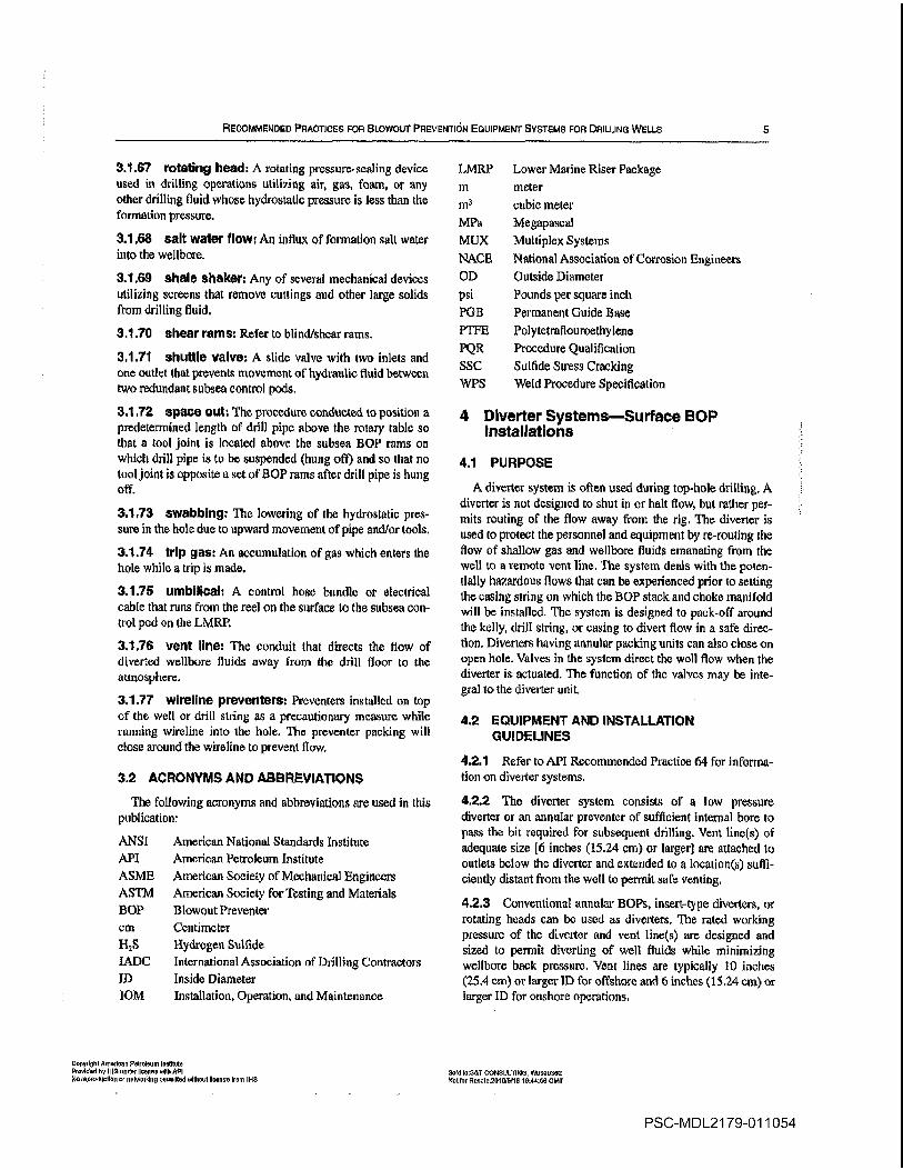
3.1.87 rotating head rotating pressure-sealing device
used indrilling operations utilizing air gas foam ci any
other drilling fluid whose hydrostatic pressure is less than the
formation pressure
3.168 salt waler flow An influx of formation salt water
into the wellbore
3.1.69 shale shaker Any of several mechanical devices
utilizing screens that remove Cuttings and other large solids
from drilling fluid
3.1.10 shear rams Refer to blind/shear rams
3.1.71 shuttle valve slide valve with two inlets and
one outlet that prevents movement of hydraulic fluid between
two redundant subsea control pods
3.1.72 space out The procedure conducted to position
predetermined length of drill pipe above the rotary table so
that tool joint is located above the subsea BOP rams on
which drill pipe is to be suspended hung oft and so that no
tool joint is opposite set of BOP rams after drill pipe is hung
off
3.1.73 swabbing The lowering of the hydrostatic pres
sure in the hole due to upward movement of pipe and/or tools
3.124 trIp gas An accumulation of gas which enters the
hole whiletrip is made
3.1.75 umbilical control hose bundle or electrical
cable that runs from the reel on the surface to the subsea con
trol pod on the LMRP
3.1.76 vent line The conduit that directs the flow of
diverted wellbore fluids away from the drill floor to the
atmosphere
3.1.77 wlreline preventers Preventers installed on top
of the well or drill string as precautionary measure while
running wireline into the hole The preventer packing will
close around the wireline to prevent flow
3.2 ACRONYMS AND ABBREVIATIONS
The following acronyms and abbreviations are used in this
publication
American National Standards Institute
American Petroleum Institute
American Society of Mechanical Engineers
American Society for Testing and Materials
Blowout Preventer
Centimeter
Hydrogen Sulfide
International Association of Drilling Contractors
Inside Diameter
Installation Operation and Maintenance
LMRP Lower Marine Riser Package
meter
cubic meter
Megapascal
Multiplex Systems
National Association of Corrosion Engineers
Outside Diameter
Pounds per square inch
Permanent Guide Base
Polytetraflouroethylene
Procedure Qualification
Sulfide Stress Cracking
Weld Procedure Specification
Diverter SystemsSurface BOPInstallations
4.1 PURPOSE
diverter system is often used during top-hole drilling
diverter is not designed to shut in or halt flow but rather per
mits routing of the flow away from the rig The diverter is
used to protect the personnel and equipment by re-routing the
flow of shallow gas and wellbore fluids emanating from the
well to remote vent line The system deals with the poten
tially hazardous flows that can be experienced prior to setting
the casing string on which the BOP stack and choke manifold
will be installed The system is designed to pack-off around
the kelly drill string or casing to divert flow in safe direc
tion Diverters having annular packing units can also close on
open hole Valves in the system direct the wall flow when the
cliverter is actuated The function of the valves may be inte
gral to the diverter unit
4.2 EQUIPMENT AND INSTALLATION
GUIDELINES
4.2.1 Refer to API Recommended Practice 64 for informa
tion on diverter systems
4.2.2 The diverter system consists of low pressure
diverter or an annular preventer of sufficient intemal bore to
pass the bit required for subsequent drilling Vent lines of
adequate size inches 15.24 cm or larger are attached to
outlets below the diverter and extended to locations suffi
ciently distant from the well to permit safe venting
4.2.3 Conventional annular BOPs insert-type diverters or
rotating heads can be used as diverters The rated working
pressure of the diverter and vent lines are designed and
sized to permit diverting of well fluids while minimizing
wellbore back pressure Vent lines are typically 10 inches
25.4 cm or larger ID for offshore and inches 15.24 cm or
larger ID for onshore operations
MPa
MIJX
NACE
OD
psi
PGB
VFE
PQR
SSC
WIS
ANSI
API
ASME
ASThI
BOP
cm
H2S
IADC
ID
lOM
Copyrighl American Pelroleuen institute
ProvIded by INS under license odiN API
No neprodueNon en networking peraeilied wllhnut Iltanne tram INS
SoW InSATGONSLJLIING W5950362
Not roe Reeaie2GIWNPut 154456 SMI
PSC-MDL21 79-011054

API RECOMMENDED PRACTICE 53
4.2.4 If the diverter system incorporates valves on the
vent lines refer to API Recommended Practice 64 this
valves should be full opening and full bore have at least the
same opening as the line in which they are installed Thesys
tern should be hydraulically controlled such that at least one
vent tine valve is in the open position before the diverter
packer closes
4.2.5 The diverter and all valves should be function tested
when installed and at appropriate times during operations to
determine that the system will function properly Refer to 17.4
and Tables and for further guidance on diverter testing
CA lITtON Fluid should be pumped through the diverter and
each diverter vent line at appropriate times during operations
to ascertain the lines is not plugged refer to API Recommended Practice 64 Inspection and cleanout ports should be
provided at all low points in the system Drains and/or heat
tracings may be required in colder climates
4.2.6 Accumulator capacity for divertevr systems should be
sized in accordance with API Recommended Practice 64
4.2.7 Consideration should be given to the low temperature
pmperties of materials used for facilities to be exposed to
unusually low temperatures
Diverter SystemsSubsea BOPInstallations
5.1 PUR POSE
Thetdiverter is used to protect the personnel and equipment
by rerOuting the flow of shallow gas and welibore fluids ema
nating from the well through an overboard vent line
divertºy is not designed to shut in or halt flow but rather per
mits riuting of the flowaway
from the rig The system deals
with the potentially hazardous flows which may be experi
enced prior so setting the casing swing on which the BOPstack and choke manifold will be installed The system is
designed to pack-off around the kelly drill string or casing to
divert flow in safe direction Diverters having annular pack
ing units can also close on open hole Valves in the system
direct the well flow when the diverter is actuated The func
tion of the valves may be integral to the diverter unit
52 EQUIPMENT AND INSTALLATION
GUIDELINES
5.2.1 Refer to API Recommended Practice 64 for informa
tion on diverter systems
5.2.2 Diverter systems on floating rigs are typically
installed below therotary table and are at the upper end of the
marine riser system There are instances where the diverter
unit is installed subsea
5.2.3 The divcrtcr system vent lines are usually large diam
eter inches 25.4 cm or larger and designed to divert
well fluids with minimal back pressure on the wellbore Flow
should be directed to the downwind side of the vessel Anyvalves in the diverter vent lines should be full opening and
full bore have at least the same opening as the line in which
installed and be either automatic or selectively sequenced
such that the wellbore flow cannot at any time be completely
closed in
5.2.4 The diverter and all valves should be function tested
when installed and at appmpriate times during operations to
determine that the system will function property Refer to 18.4
and Tables and for further guidance on diverter testing
CAUTION Fluid should be pumped through the divcrter and
each diverter vent line at appropriate times during operations to
ascertain the lines is not plugged Inspection and cleanout
ports should be provided at all low points in the system Drains
and/or heat tracings may be required in colder climates
525 Accumulator capacity for diverter systems should be
sized in accordance with API Recommended Practice 64
5.2.6 Consideration should be given to the low temperature
properties of materials used for facilities to be exposed to
unusually low temperatures
Surface BOP Stack Arrangements
6.1 EXAMPLE BOP STACK ARRANGEMENTS
6.1.1 Example arrangements for BOP equipment are based
on rated working pressures Example stack arrangements
shown in Figures to should prove adequate in normal
environments for rated working pressures of 2K 3K 5K10K 15K and 20K Arrangements other than those illus
trated may be equally adequate in meeting well requirements
and promoting safety and efficiency
2000 psi 13.8 MPa3000 psi 20.7 MPa5000 psi 34.5 MPa10000 psi 69.0 MPa15000 psi 103.5 MPa20000 psi 138.0 MPa
Note psi 0.006894757 MPa
6.2 STACK COMPONENT CODES
Every installed ram flOP should have as minimum
working pressure equal to the maximum anticipated sur
face pressure to be encountered The recommended component codes for designation of flOP stack arrangements
are as follows
Rated Working Presssre
2K
3K
5K
10K
15K
20K
Copydglct America PIoIom InalIbdo
Provided by ibiS under bonse wills APt
No repcoduolcn or netoorklrg porm6ird without Ilccooe irocc iNS
sold 60651 CONSULTING WONOS3NS
NoI for Reclo2610I6118 164456 CMT
PSC-MDL21 79-011055
RECOMMENPED PRAcTIcEs FOR BLOWOUT PREVENTION EQUIPMENT SYSTEMS FOR DRILLING WELLS
rotating head
annular type HOP
single ram type HOP with one set of rams either
blank or for pipe as operator prefers
Rd double ram type HOP with two sets of rams posi
tioned in accordance with operators choice
triple ram type DO with three sets of rams posi
tioned in accordance with operators choice
drilling spool with side outlet connection for choke
and kill lines
1000psi rated working pressure
30 components are typically described upward from the
uppermost piece of permanent wellhead equipment or from
the bottom of the HOP stack HOP stack may befully
iden
tified by very simple designation such as
10K- IY/3-SRRA
This HOP stack would be rated 10000 psi 69.0 MPaworking pressure would have throughbore of l3I inches
34.61 cm and would be arranged as in Figure 2a
Annular HOPs may have lower rated working pressure
than the ram HOPs
6.3 RAM LOCKS
Ram type preventers should be equipped with extension
hand wheels or hydraulically operated locks
6.4 SPARE PARTS
The following recommended minimum HOP spare parts
for the service intended should be carefully stored main
tained and readily available
complete set of ram rubbers for each size and type of
ram HOP being used
complete set of bonnet or door seals for each size and
type of ram HOP being used
Plastic packing for HOP secondary seals
Ring gaskets to fit end connections
spare annular BOP packing element and complete set
of seals
flexible choke or kill line if in use
6.5 PARTS STORAGE
When storing HOP metal parts and related equipment they
should be coated with protective coating to prevent rust
Storage of elastomcr pails should be in accordance with manufacturers recommendations
6.6 DRiLLING SPOOLS
Choke and kill lines may be connected either to side outlets
of the HOPs or to drilling spool installed below at least one
HOP capable of closing on pipe Utilization of the HOP side
outlets reduces the number of stack connections and overall
BOP stack height However drilling spool is used to provide
stack outlets to localize possible erosion in the less expensive
spool and to allow additional space between preventers to
facilitate stripping hang off nndlor shear operations
6.6.1 Drilling spoots for HOP stacks should meet the fol
lowing minimum qualifications
3K and 5K arrangements should have two side outlets no
smaller than 2-inch 5.08 cm nominal diameter and be
flanged studded or hubbod 10K 15K and 20K arrange
ments should have two side outlets one 3-inch 7.62 cm and
one 2-inch 5.08 cm nominal diameter as minimtjm and be
flanged sudded or hubbed
Have vertical bore diameter the same internal diameter
as the mating BOPs and at least equal to the maximum bore
of the uppermost casing/tubing head
1-lave rated working pressure equal to rated working
pressure of the installed ram HOP
6.6.2 Fordrilling operations wellhead outlets should not
be employed for choke or kilt tines
Subsea BOP Stack Arrangements
7.1 EXAMPLE BOP STACK ARRANGEMENTS
bxample arrangements for SO equipment are based on
rated working pressures Example stack arrangements shown
in Figures and should prove adequate in normal enviroti
monts for rated working pressures of 2K 3K 5K 10K 15K
and 29K Arrangements other than those illustrated may be
equally adequate in meeting well requirements and promot
ing safety and efficiency
2000 psi 13.8 MPa3000 psi 203 MPa5000 psi 34.5 MPa10000 psi 69.0 M1a15000 psi 103.5 MPa20000 psi 138.0 MPa
KnIed Working Pressure
2K
3K
5K
10K
15K
20K
CpyIhI Aomion PIrdeuii Iulule
Pryldd by INS umi II. oils API
reprtIIo or ntoobIg pnIIIedwlthoot icne from INS
Notc psI 0.006894757 MPa
sold I551 COSSULTING W0955302
NIfr Rl20155I18 154456 OMT
PSC-MDL21 79-011056

API RECOMMENDED PRACTIc 53
Choke and
kill line ouet
Arrangement SRRDouble Rant Type Preventers Fid Optional
Drilling iipool and its location In the stack arrangement is optional
Figure 1Exampe Arrangements for 2K Rated Working Pressure ServiceSurface BOP tnstallations
CopyrlgfltAmerieav Peb loom lnotiiute
Provided by hid underlicelvee wuSi API
Noreproduodorr or nebeeddng permuted Wlihvui beebe from li-IS
Sold 0551 CONSULTING WO9O562
Not for Rusobo2Ol Sf5118 hB446S OMT
Arrangement RSRGDouble Barn Type Preventers FId Optional
PSC-MDL21 79-011057
RECOMMENDED PRACTICES FOR BLOWOUT PREVENTIOn EQUIPMENT.SYSTEMS FOR DRILLING WELLS
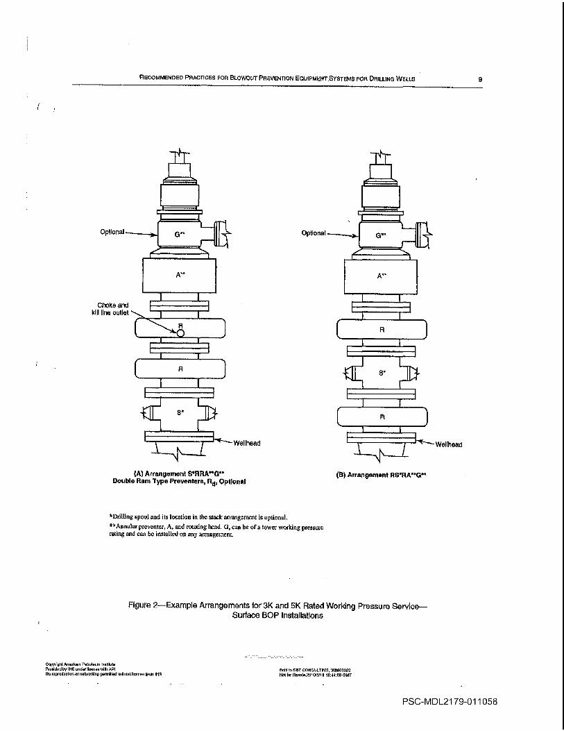
Arrangement SRHAGDouble Rane Type Preventera Optional
tDthlting spool and its location in the stack arrangement is optional
flUjpreventer and rotating head can be of lower working pressure
rating and can be installed on any arnengernent
Figure 2Example Arrangements tor BK and 5K Rated Working Pressure ServiceSurface BOP Installations
Copyright Aoirrlomr Petroleum InstItute
Prooldorttry
He under Iloen rennlth API
No roprortuotion or networkIng permlllortwtllroot Iloonoo from INS
moM toSST CoSsULrINu W0509362
Hotter Rooole201a15115 104405 GET
choke and
kill line outlet
Welihead -Welihead
Arrangement R95flAG
PSC-MDL21 79-011058

10 API RcoMMENDao PItACTICE 53
kill
Optional
Drilling spool and its location in the stackacinrigement
is optional
Aunul preventer arid rotating head can be of lower working pressure
isting and can be installed on any anangement
fl Arrangement flSRRMQDouble Rem Type Preventers Rd Optional
Figure 3Example Arrangements for 10K 15K and 20K Working Pressure ServiceSurface BOP Installations
Copyrightpmorlcoe P01010cm Inoiliroto
Provided by it-IS oindnr licence with API
tIn reproduoswn or noiwnrkln permitted wilboul toorme tromP-It
Sold torSuT CONSIJLT1N5 W5955302
Not for Reeolo2510r5115 104450 ChIT
Arrangement SRRRADouble Rem Type Preventere Eld OptIonal
PSC-MDL21 79-011059

RECOMMENDSD PRACTICES FOR BLOWOUT PREVENTION EQUIPMENT SYSTEMS FOR DRILLING WELLS 11
Arrangement CWSACR2K Rated Working Pressure Only
Arrangement CwRRAC9Double Ran Type Preventers R1 Optional
Arrangement CWRRCRADouble Ram Type Preventers R4 Optional
Figure 4Example Arrangements for 2K and BK Rated Working Pressure ServiceSubsea BOP installations
CupyriNhI Amorluon tutooloOm lootibulo
Ptoutdud by INS Linden unease wiNo 1N
No ropoodoodon or ooboorblog yermilted without Iloaooo bonn il-IS
Sold loOS1 CONSULTiNG WSNSS362
Not toe 0000lo20101501N iO44Ny SUIT
Arrangement CWRACR
PSC-MDL21 79-011060

12 AP RECOMMENDED PRACTICE 53
II
tii
.i
Copydohi Amooooui Potrolotun moutoN
Provided by INS undo license tACIt OPI Sold IoST CONSULTING W0889362
No cvprodIoIloo or neIwoikiCrS permitted Without license bore IHC Not or Rossln281 018118 164468 GMT
PSC-MDL21 79-011061
FtecoMMErrioEo PRACTICES FOR Biowoul PREvEMTI0I1 EoulPMsrrrr SYstaMs FOR DRJLuNo WELLS 13
1.2 STACK COMPONENT CODES
Every installed ram flOP should have as minimum
working pressure equal to the maximum anticipated surface
pressure to be encountered The recommended component
codes for designation of flOP stack arrangements are as fol
lows
annular type HOPupperAL annular type HOPlower
single ram type BOP with one set of rams either
blank or for pipe as operator prefers
Rd double ram type HOP with two sets of rams posi
tioned in accordance with operators choice
triple ram type HOP with three sets of rams posi
tioned in accordance with operators choice
drilling spool with side outlet connection for choke
and kill lines
1000 psi rated working pressure
CR riser connector used to attach the lower marine riser
package LMRP to the HOP stack and has rated
working pressure equal to or greater than the com
ponents above it
wellhead connector used to attach wellhead and
preventers to each other connector should have
minimum rated working pressure equal to the HOPstack rated working pressure
The typical sequence for numbering the ram BOPs in
subsea stack is from the bottom up HOP stack may be fully
identified by very simple designation such as
10K 18-3/4 CWRJRdALCRAU
This HOP stack would be rated 10000 psi 69.0 MPaworking pressure would have throughbore of 8/4 inches
47.63 cm and would be arranged as in Figure
Annular HOPs are typically designated as lower bottomannular and upper top annular Annular HOPs may have
lower rated working pressure than the ram HOPsThe identifying labels for the choke and kill lines are arbi
trary Traditionalty where circulating line is connected to an
outlet below the bottom ram HOP this circulating line is gen
erally designated as the kill line Whether the kill line is con
nected to an outlet below the lowermost ram flop it is
preferable to have one choke line and one kill line connection
above the bottom rain HOP In stack arrangements where this
bottom connection does not exist then either or both of the
two circulating lines may alternately be labeled as choke
line
Rig-specific stack identifying nomenclature should be
made part of the drilling program
7.3 SUSSEA SOP STACK ARRANGEMENTS
7.3.1 The ram HOP positions and outlet arrangements on
subsea HOP stacks should provide reliable means to handle
Copyright American Petroleum lmtlrutu
Provided b6 Il-PS under licence mill API
lie cepccdeclicn or rretrnochiry ponnitledwlihnutlleooo From 165
potential well control events Specifically for floating opera
tions the arrangement should provide means to
Close in on the drill string and on casing or liner and allow
circulation
Close and seal on open hole and allow volumetric well
control operations
Strip the drill string using the annular HOPsHang off the drill pipe on ram HOP and control the well-
bore
Shear logging cable or the drill pipe and seal the wellbore
Disconnect the riser from the BOP stack
Circulate the well after drill pipe disconnect
Circulate across the HOP stack to remove trapped gas
There are several arrangements of ram HOP positions and
side outlets that may satisfy the above
7.3.2 Some differences relative to surface BOP systems
are
Choke and kill lines normally nrc connected to ram pre
venter body outlets to reduce stack height and weight and to
reduce the number of stack connections
Spools may be used to space preventers for shearing tubu
lars hanging off drill pipe or stripping operations
Choke and kill lines are manifolded such that each can be
used for either purpose
Blind/shear rams arc used in place of blind rams
Ran preventers should be equipped with an integral or
remotely operated locking system
7.4 SPARE PARTS
The following recommended minimum HOP spare parts
for the service intended should be carefully stored main
tained readily available
complete set of ram rubbers for each size and type of
ram BOP installed
complete set of bonnet or door seals for each size and
type of ram HOP installed
Ring gaskets to fit end connections
spare annular HOP packing element and complete set
of seats
flexible choke or kill line if in use
75 PARTS STORAGE
When storing HOP metal parts and related equipment they
should be coated with protective coating to prevent rust
Storage of elastomer parts should be in accordance with manufacturers recommendations
7.6 DRILLING SPOOLS
7.6.1 Choke and kill lines may be connected either to side
outlets of the HOPs or to drilling spool installed below at
Sold tmST CONSULTING W0009362
Mel Inn Rounl2010/S4j6 164456 GMT
PSC-MDL21 79-011062
14 API RECOMMENDED PRACTIcE 53
least one BOP capable of closing on pipe Utilization of the
BOP side outlets reduces the number of stack connections
and overall BOP stack height Typically drilling spools are
not installed on subsea BOPs however drilling spool can
be used to provide stack outlets to localize possible erosion
in the less expensive spool and to allow additional space
between preventers to facilitate stripping5 hang off and/or
shear operations
7.6.2 Drilling spools for BOP stacks should meet the fol
lowing minimum specifications
3K and 5K arrangements should have two side outlets no
smaller than 2-inch 5.08 cm nominal diameter and be
flanged studded or hubbed 10K 15K and 20K arrange
ments should have two side outlets oae 3-inch 7.62 cm and
one 2-inch 5.08 cm nominal diameter as minimum and be
flanged studded or hubbed
Have vertical bore diameter the same internal diameter
as the mating BOPs and at least equal to the maximum bore
of the uppermost casing/tubing head
Have rated working pressure equal to the rated working
pressure of the installed ram BOP
Choke Manifolds and Choke LinesSurface BOP Installadons
8.1 GENERAL
The choke manifold consists of high pressure pipe fittings
flanges valves and manual and/or hydraulic operated adjust
able chokes This manifold may bleed off welibore pressure
at controlled rate or may stop fluid flow from the wellbore
completely as required
8.2 INSTALLATION GUIDELINESCHOKEMANIFOLD
Recommended practices for installation of choke mani
fods for surface installations include
Manifold equipment subject to well and/or pump pressure
normally upstream of and including the chokes should have
working pressure equal to or greater than the rated working
pressure of the ram BOPs in use This equipment should be
tested when installed in accordance with provisions of Sec
tion 17
For working pressures of 3000 psi 20.7 MPa and above
flanged welded clamped or other end connections tbat are in
accordance with API Specification 6A should be employed
on components subjected to well pressure
The choke manifold should be placed in readily accessi
ble location preferably outside thc rig substructure
Although not shown in the example equipment illustra
tions buffer tanks are sometimes installed downstream of the
choke assemblies for the purpose of manifolding the bleed
Copyright knorluun Petroleum Inedlnjte
Pooldud by hIS undo license witS API
No reproducNnn etwurklny peernitted without license tunn IRS
lines together When buffer tanks are employed provision
should be made to isolate failure or malfunction
All choke manifold valves should be full bore No valves
are recommended between the 80 stack and the choke
manifold for Installations with rated working pressures of
5n000 psi 34.5 IviPa and above One of these two vatves
should be remotely controlled During operations all valves
should be fully opened or fully closed
minimum of one remotely operated choke should be
installed on 10000 psi 69.0 MPh 15000 psi 103.5 MPhand 20000 psi 1380 MPh rated working pressure manifolds
Choke manifold configurations should allow for re-routing
of flow in the event of eroded plugged or malfunctioning
parts without interrupting flow control
Consideration should be given to the low temperature
properties of the materials used in installations to be exposed
to unusually low temperatures and should be protected from
freezing by heating draining filling with appropriate fluid or
other appropriate means
Pressure gauges suitable for operating pressure and drill
ing fluid service should be installed so that drill pipe and
annulus pressures may be accurately monitored and readily
observed at the station where well control operations are to be
conducted
The choke control station whethcr at the choke manifold
or remote from the rig floor should be as convenient as possi
ble and should include all monitors necessary to furnish an
overview of the well control situation The ability to monitor
and control from the same location such items as standpipe
pressure casing pressure pump strokes etc greatly
increases well control efficiency
Rig air systems should be checked to assure their ade
quacy to provide the necessary pressure and volume require
ments for controls end chokes The remotely operated choke
should be equipped with an emergency backup system such
as manual pump or nitrogen for use in the event rig air
becomes unavailable
8.3 INSTALLATION GUIDELINESCHOKE LINES
8.3.1 The choke line and manifold provide means of
applying back pressure on the formation while circulating out
formation fluid influx from the weilbore following an influx
or kick Refer to API Specification 6C for equipment spe
cific requirements for choke manifolds Ilexible choke lines5
and articulated line assemblies The choke line which con
nects the BOP stack to the choke manifold and lines down
stream of the choke should
Be as straight as possible
Because erosion at bends is possible during operations
consideration should be given to using flow targets at
bends and on block ella and lees The degree to which pipe
bends nre susceptible to erosion depends on the bead
radius flow rate flow medium pipe wall thickness and
SnId toSNT CONSULTING W69691S2
Net InnlIIe26tQtSiIl 164456 GMT
PSC-MDL21 79-011063

RECOMMENDED PRACTICES FOR BLOWOUT PnnvENTIoN EQUIPMENT SYSTEMS FOR DRILLING WELLS 15
pipe material However in general short radius pipe
bends Rid 10 should be targeted in the direction of
expected flow For large radius pipe bends Rid 10 tar
gets are generally unnecessary Bends sometime have
wall thickness greater than the straight pipe in the choke
system such as the next higher schedule to further com
pensate for the effect of erosion 90 block elis and tees
should be targeted in the direction of flow
Where
Radius of pipe bend measured at the centerline
Nominal diameter of the pipe
Fur flexible lines consult the manufacturers guide
lines on working minimum bend radius to ensure proper
length determination and safe working configuration
For articulated line assemblies consult with the manufacturers written specifications to determine the degree of
relative movement allowable between end points
lx Be firmly anchored to prevent excessive whip or vibration
Have bore of sufficient size to prevent excessive erosion
or fluid friction
Minimum recommended size for choke lines is 2-inch
5.05 cm nominal diameter for 3K and 5K arrangements
and 3-inch 7.62 cm nominal diameter for 10K 15K and
20K arrangements
Minimum recommended nominal inside diameter for
lines downstream of the chokes should be equal to or
greater than the nominal connection size of thc chokes
Lines downstream of the choke manifold arc not nor
mally required to contain pressure refer to Tables and
for testing considerations
For air or gas drilling operations minimum 4-inch
10.16cm nominal diameter lines are recommended
The bleed line the line that bypasses the chokes
should be at least equal in diameter to the choke line This
line allows circulation of the well with the preventers
closed while maintaining minimum back pressure It
also permits high volume bleed off of well fluids to relieve
casing pressure with the preventers closed
8.3.2 Figures through illustrate example choke mani
folds for various working pressure service Refinements or
modifications such as additional hydraulic valves and choke
runs wear nipples downstream of chokes redundant pressure
gauges and/or manifolding of vent lines may be dictated by
the conditions anticipated for particular well and the degree
of protection desired The guidelines discussed and illustrated
represent examples of industry practice
8.4 MAINTENANCE
Preventive maintenance of the choke assembly and con
trols should be performed regularly checking particularly for
wear and plugged or damaged fines Frequency of mainte
nance will depend upon usage Refer to Section 17 for recom
inendations for testing inspection and general maintenance
of choke manifold systems
Rated_woricing pressure
Figure 6Example Choke Manifold Assembly for 2K and 3K Rated Working Pressure Service
Surface BOP Installations
Copyright Amottnon Pefroteum Institute
Pnootdod by tHO under license shtth API
Mn reproduction or networking permitted without license from tHS
gold InfrT COhBIJLTING tN0b193d2
Molter hooto.201 Oil/tI 64416 i3MT
To pit and/or
mud/gas separatorf
overboard
Rated working pressure
PSC-MDL21 79-011064

API RECOMMENDED PRAOTICE 53
Figure 7Example Choke Manifold Assembly for 6K Rated Working Pressure ServiceSurface BOP Installations
Nominal
7.62cm
Copyri5hl American Petroleum leetilule
Provided by iHS undo licence ceitli API
No neprudeullve on networkbnu permitted without licence truce Ills
Sold tuS5T CONSULTING W0551352
Nut ten tlecalu251 016/It 164450 GMT
Adjustable cho1co
Remote hydraulically
operated valve
Rated working pressure
NomInal
762cm
To pit and/or
mud/gas separator/
overboard
Nominal
Remotely operated 5.06cmor adjustable choke
Rated working pressure
Remotely
operated choke
Remote hydraulically
operated valve
Nominal
5.080m
To pit and/or
mud/gas separator/
overboard
Bleed tine to
pit/overboard
outlet
Rated working pressure
1-
optional
Pt
Remotely operated
or adjustable choke
To pit and/or
mud/gas separator/
overboard
NomInal
5.08cm
Rated workIng pressure
Figure 8Example Choke Manifold Assembly for 10K 15K and 20K Rated Working Pressure ServiceSurface BOP Installations
PSC-MDL21 79-011065

8.5 SPARE PARTS
An adequate supply of spare parts is important for compo
nents subject to wear or damage or whose failure seriously
reduces the effectiveness of the manifold or choke line Stan
dardization of components is recommended to minimize the
inventory required Although the inventory will vary from rig
to rig generalized recommended minimum spare parts list
includes
One complete valve for each size installed
Two repair kits for each valve size utilized
Parts for manually adjustable chokes such as flow tips
inserts packing gaskets 0-rings disc assemblies and wear
sleeves
Parts for remotely controlled chokes
Miscellaneous items such as hose flexible tubing electri
cal cable pressure gauges small control line valves fittings
and electrical components
Choke ManifoldsSubsea BOPInstallations
9.1 GENERAL
The choke manifold assembly for subsea BOP installations
has the same purpose as for surface installations viz it is
used to bleed off the wellbore pressure at controlled rate or
may stop fluid flow from the wellbore completely as
required Figure is an example choke manifold assembly for
subsea installation for 5000 psi 34.5 MPa 10000 psi
69.0 MPa or 15000 psi 103.5 MPa rated working pres
sure service This assembly differs from surface installation
in that the choke and kill lines are manifolded to permit
pumping or flowing through either line Other features
include remotely controlled adjustable choke and manu
ally adjustable choke system to permit control through either
the choke or kill line and tie-ins to both drilling fluid and
cement uniL pump systems refer to Figure
9.2 INSTALLATION GUIDELINES
9.2.1 Recommended practices for installation of choke
manifolds for subsea installations include
Manifold equipment subject to well and/or pump pressure
normally upstream of and including the chokes should have
minimum working pressure at least equal to the rated work
ing pressure of the ram SOPs in use This equipment should
be tested when installed in accordance with provisions of
Section 18
For working pressures of 3000 psi 20.7 MPa and above
flanged welded hubbed or other end connections that are in
accordance with API Specification 6A should be employed
on components subjected to well pressure
17
Although not shown in the example equipment illustra
tions buffer tanks are sometimes installed downstream of the
choke assemblies for the purpose of tnanifolding the bleed
lines togethet When buffer tanks are employed provision
should be made to isolate failure or malfunction
The main header should be 3-inch 7.62 cm nominal
diameter or larger All other components should be 2-inch
5.08 cm nominal diameter or larger The assembly should
have miaimum number of turns and be securely anchored
Turns in the assembly should be targeted in both directions
All choke manifold valves should be full bore During
operations all valves should be fully opened or fully closed
minimum of one remotely operated choke should be
installed on 10000 psi 69.0 MPa 15000 psi 103.5 MPaand 20000 psi 138.0 Mla rated working pressure manifolds
Choke manifold configurations should allow for re-routing
of flow in the event of eroded plugged or malfunctioning
pans without interrupting flow control
Consideration should be given to the low temperature
properties of the materials used in installations to be exposed
to unusually low temperatures and should be protected from
freezing by heating draining filling with appropriate fluid or
other appropriate means
Pressure gauges suitable for operating pressure and drill
ing fluid service should be installed so that drill pipe and
annulus pressures may be accurately monitored and readily
observed at the station where well control operations are to be
conducted
The choke control station whether at thc choke manifold
or remote from the rig floor should be as convenient as possi
ble and should include all monitors necessary to furnish an
overview of the well control situation The ability to monitor
and control from the same location such items as standpipe
pressure casing pressure pump strokes etc greatly
increases well control efficiency
Rig air systems should be checked to assure their ade
quacy to provide the necessary pressure and volume require
ments for cuntrols and chokes The remotely operated choke
should be equipped with an cmergency backup system such
as manual pump or nitrogen for use in the eventrig
air
becomes unavailable
Initial testing of the choke manifold assembly to the rated
working pressure of the ram BOPs should be performed
when the BOP stack is on the test stump prior to running
subsea Suhsequent pressure tests of the choke manifold
assembly should be conducted in accordance with applicable
provisions of Section 18
Lines downstream of the chokes or the last valve down
stream of chokes are normally not required to contain rated
manifold working pressure refer to Tables and for testing
considerations
Lines downstream of the choke manifold should be
securely anchored be of sufficient size to permit reasonable
flow rates without excessive friction and permit flow dircc
RecOMMENDED PRAcTIcEs FOR BLOWOUT PnEvENTI0N EQUIPMENT SvrEMs on DRILLING WELLs
Copyright AmIe PoIroounoIroIIIoto
Pruododlop
INS under Iloeooo with API
NoropoodLIoliol or oetworklos poIftd without Ilcouno worn PlO
Sold tuShI CCNaiJLIINC W0900302
Not Roolo20ISl5/IO Iw44On CMI
PSC-MDL21 79-011066
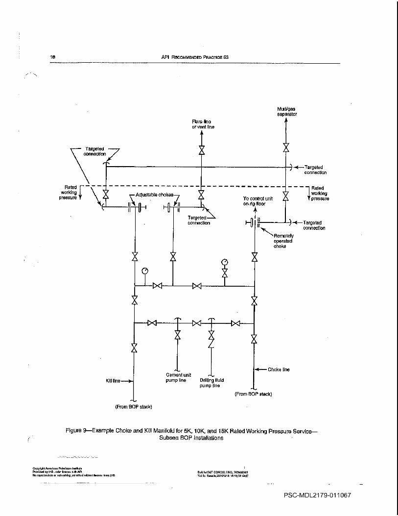
18 API RECOMMENDED PRAC11CE 53
Rated
working
pressure
Figure 9Example Choke and Kill Manitold for 5K 10K and 15K Rated Working Pressure ServiceSubsea BOP Installations
Copyright Anrorloen PrrfroIounv Inelliule
Provided by lIS Under ilcenne with dPi
Mo reprortuclicn or networking permuted wiorootlloonea from It-IS
Sold IeST CONSULTING W0900352
Ntot to Reoolo.201001I8 1644r66 GMT
-Targeted
connection
Kill
Oemert unit
pump line Drilling fluid
pump tine
Choke line
From BOP stack
From BOP stack
PSC-MDL21 79-011067

REcoMMENDED PRACTICES FOR BLOWOUT PREVENTION EQUIPMENT SYSTEMS FOR DRILLING Wcu.s
tion either to mudlgas separator vent lines or to production
facilities or emergency storage
9.2.2 Figure illustrates an example choke manifold Con
figurations of choke manifolds may vary widely as result of
space limitations operators policies etc Refinements or
modifications such as additional hydraulic valves dnd choke
runs wear nipples downstream of chokes redundant pressure
gauges andlor manifolding of bypass lines may be dictated
by the conditions anticipated for particular well and the
degree of protection desired The guidelines discussed and
illustrated represent examples of industry practice
93 MAINTENANCE
Preventive maintenance of the choke assembly and con
trols should be performed regularly checking particularly for
wear and plugged or damaged lines Frequency of mainte
nance will depend upon usage Refer to Section 18 for recom
mendations for testing inspection and general maintenance
of choke systems
9.4 SPARE PARTS
An adequate supply of spare parts is important for components subject to wear or damage or whose failure seriously
reduces the effectiveness of the manifold Standardization of
components is recommended to minimize the invcntory
required Although the inventory wilt vary iromrig to rig
generalized recommended minimum spare parts jet includes
One complete valve for each size installed
Two repair kits for each valve size utilized
Parts for manually adjustable chokes such as flow tips
inserts packing gaskets 0-rings disc assemblies and wear
sleeves
Parts for the remotely controlled chokes
Miscellaneous items such as hose flexible tubing electri
cal cable pressure gauges small control line valves and fit
tings and electrical components
10 Kill LinesSurface BOP Installations
10.1 PURPOSE
10.1.1 Kill lines are an integral part of the surface equip
ment required for drilling well control The kill line system
provides means of pumping into the wellbore when the nor
mal method of circulating down through the kelly or drill pipe
cannot be employed The kill line connects the drilling fluid
pumps to side outlet on the BOP stack The location of the
kill line connection to tha stack depends on the particular con
figuration of BOPs and spools employed the connection
should be below the rain type BOF most likely to be closed
Figures 10 It and 12 illustrate example kill line installations
for various working pressure scrvice
Copyright Annlou Petroleum iretitule
Provided by IRS under license udth API
No reproduction or rtIworidng pamiiIed wiiheitucene Item IriS
10.1.2 On selective high-pressure critical wells remote
kill line is commonly employed to permit use of an auxiliary
high pressure pump if the rig pumps become inoperative or
inaccessible This line normally is tied into the kill tine near
the blowout preventer stack and extended to site suitable for
location of pump This site should be selected to afford
maximum safety and accessibility
10.2 INSTALLATION GUIDELINES
10.2.1 The same guidelines which govern the installation
of choke manifolds and choke lines apply to kill line installa
tions Refer to API Specification t6C for equipment specifi
cations for kill lines The more important recommendations
include
All lines valves check valves and flowfittings should
have working pressure at least equal to the rated working
pressure of the ram l3OPs in use This equipment should be
tested when installed in accordance with provisions of Sec
tion 17
For working pressures of 3000 psi 20.7 MPa and above
flanged welded hubbed or other end connections that are in
accordance with API Specification 6A should be employed
Components should be of sufficient diameter to permit
reasonable pumping rates without excessive friction The
minimum recommended size is 2-inch 5.08 cm nominal
diameter
Two full bore manual valves plus cheek valve or two full
bore valves one of which is remotely operated between the
stack outlet and the kill line are recommended for installa
tions with rated working pressure of 5000 psi 34.5 MPa or
greater Refer to Figures II and 12
Periodic operation inspection testing and maintenance
should be performed on the same schedule as employed for
the BOP stack in use refer to 17.10
All components of the kill line system should be protected
from freezing by heating draining filling with proper fluid
or other appropriate means
Consideration should be given to the low temperature
properties of the materials used in installations to be exposed
to unusually low temperatures aitid should be protected from
freezing by heating draining filling with appropriate fluid or
other appropriate means
11 Lines should be as straight as possible When bends are
required to accommodate either dimensional variations on
sequential rig ups or to facilitate hookup to the BOP the larg
est bend radius allowable under the hookup restraints should
be provided Following is guidance for bends in different
types of lines
For rigid pipe the bend radius should he maximized
Because erosion at bends is possible during operation
consideration should be given to using flowtargets at
bends and on block elLc and tees The degree to which pipe
bends are susceptible to erosion depends on the bend
Sold toSST CONSULTING W0950302
Not for Reoel2S15/5/lS 10t44SO CMI
PSC-MDL21 79-011068

20 API RECOMMENDED PRACTICE 53
CopyrIght Amoilcen PeIoum tnetitrjle
ProvIded b6 113 tinder Iloerse wile API
Noroyrodseflon or rretworkIn perwlted sllhwitllorrre row HI
Hydraulically operated
orcheck valve
From
drilling_______________ _____________
Iluld
pump Nominal 5.08cm
SOPstack
outlet
20 Nominal 5.08cm
Sold loST CONSULTING W0955362
tier for ReealeZOl SlSllS 164456 tNT
Figure 10Example Kill Line Assembly for 2K and 3K Rated Working Pressure ServiceSurface BOP Installations
Threaded Connections optional for 2K rated working pressure service
Hydraulically operated
or check valve
Recommended when
remote pumpline is installed
Remote
kill line
Remote pumpconnection optional
FromSOP
drilling
stackfluid
outletpump
Figure 11Example Kill Line Assembly for 5K 10K and 15K Rated Working Pressure ServiceSurface SOP installations
FromBOPstack
outletpump
Remote
kill line
Remote pumpconnection optional
FIgure 12Example Kili Line Assembly for 5K 10K and 15K Rated Working Pressure ServiceSurface SOP Installations
Hydraulically
operated valve
NomInal S.C 8cm
PSC-MDL21 79-011069

RECOMMENDED PRACTICES FOR BLOWOUT PREVENTION EQUIPMENT SYSTEMS FOR DRILLINO WELLS 21
radius flow rate flow medium pipe wall thickness and
pipe material However in general short radius pipe
bends Rid 10 should be targeted in the direction of
expected flow For large radius pipe bends Rid 10 tar
gets are generally unnecessary Bends sometime have
wall thickness greater than the straight pipe in the killsys
tem such as the next higher schedule to further compensate for the effect of erosion 90 block ells and tees
should be targeted in the direction of flow
Where
Radius of pipe bend measured at the centerline
Nominal diameter of the pipe
For flexible lines consult the manufacturers guide
lines on working minimum bend radius to ensure proper
length determination and safe working configuration
For articulated line assemblies consult the nianufac
turers written specifications to determine the degree of
relative movement allowable between the end points
All lines should be firmly anchored to prevent excessive
10.2.2 The kill line should not be used as fill-up line dur
ing normal drilling operations
10.3 MAINTENANCE
Preventive maintenance of the kill line assembly should he
performed regularly checking particularly for wear and
plugged or damaged lines Frequency of maintenance will
depend on usage Refer to Section 17 for recommendations
on testing inspection and general maintenance of kill mani
fold systems
10.4 SPARE PARTS
An adequate supply of spare parts is important for compo
nents subject to wear or damage or whose failure seriously
reduces the effectiveness of the kill line Standardization of
components is recommended to minimize the inventory
required Although the inventory will vary from rig to rig
generalized recommended spare parts list includes
One complete valve for each size installed
Two repair kits for each valve size utilized
Miscellaneous items such as hose flexible tubing electri
cal cable pressure gauges small control line valves fittings
and electrical components
11 Choke and Kill LinesSubsea BOPInstallations
11.1 GENERAL
For subsea BOP installations choke and kill lines are con
nected through the choke manifold to permit pumping or
flowing through either line
112 INSTALLATION DESCRIPTION
Choke and kill lines for subsea BOP installations are
installed opposite one another on the exterior of the marine
riser refer to Figure 13 Choke and kill lines are normally 3-
inch 7.62 cm nominal diameter or larger The identifying
labels for the respective subsea choke and kill lines are arbi
trary Traditionally where circulating line is connected to an
outlet below the lowermost ram HOP this circulating line is
generally designated as kill line
Whether or not the kill line is connected to an outlet below
the lowermost ran DO it is preferable to have one choke
line and one kill line connection above the lowermost ram
DO
11.3 INSTALLATION GUIDELINES
Some of the more important considerations concerning
subsea choke and kill lines are
Selection of choke and kill line connectors must take into
consideration the ease of connect/disconnect operations and
the dependability of sealing elements for thoseemergency sit
uations where it is necessary to disconnect the riser from the
BOP stack and then reconnect again prior to resuming normal
operations
Connector pressure sealing elements should be inspected
changed as required and tested before being placed in ser
vice Periodic pressure testing is recommended during instal
lation Pressure ratings of all lines and sealing elements
should equal or exceed the rated working pressure of the ram
BOPs
Subsea choke/kill lines are connected to their counter
parts on adjoining riser joints by box-and-pin stab-in cou
plings The box contains an elastomeiic radial seal that
expands against the smooth abrasion-resistant sealing sur
face of the pin when the line is pressurized The stab-in cou
plings also facilitate fast makeup while deploying the marine
riser
Bach DO outlet connected to the choke or kill line should
have two full-opening valves adjacent to the preventers
These valves are hydraulically operated pressure assist open
and spring close Spring closure can also be assisted with
hydraulic pressure Periodic pumping through the valves is
necessary since they are normally closed and may become
plugged if not occasionally flushed
whip or vibration
Copyrlel.tdocedco Patrolvi iiflvf
Provided by Il-Is ovdorfionoo oAth 5lNo rprod.ucficr 01 votWrollIr.j permlitodoiilrooi licence from illS
ScId tosT QOI4SLILTI NO 150909362
Not for R000io20153116 164456097
PSC-MDL21 79-011070

22 API RECOMMENDED PRACTICE 83
Integral type
May be reversed
Figure 13Example Riser Mounted Kill and Choke Lines for Subsea GOP Installations
CopyrightAmedeun Petroleum InsIlule
ProeIdod by IHS under license oAth API
Ida reproduntlon or irelmorkirry permitted wIttrouliI ones 1mm IllS
Sotri IoST CONSULTIPIO W0909362
Wolfer Senale.2010l5/ln 164455 GUll
Choke line
end
end
PSC-MDL21 79-011071
RECOMMENDED PRACTICES FOR BLOWOUT PREVENTION EQUIPMENT SYSTEMS FON DRILLING WELLS 23
Location of the choke and kill tinc openings on the BOPstack depends on the particular configuration of the preven
ters and the operators preferred flexibility for well control
operations Example arrangements are shown in Figure 14
Other arrangements may be equally adequate to meet well
control requirements Refer to 7.3 for guidance on arrange
ment considerations
flexible connections required for choke and kill lines both
at the top and bottom of the marine riser should have pres
sure rating equaling or exceeding the rated working pressure of
the rain BOPs Figures 15 and 16 illustrate example flexible
choke and kill connections for subsea SOP installations
The flexible choke and kill line manufacturers guidelines
should be consulted to determine/verify moon pool choke and
kill line operating parameters
It is important to consult the flexible choke/kill line manufacturers guidelines for proper length determination and
proper routing to ensure nonentrapment of pods and safe
operating configuration which will allow full-designed
deflection of the flex/ball joint The flexible line manufacturer
should be consulted prior to any modifications to the lower
marine riser package to ensure subsequent safe working con
ditions for the flexible lines
All choke and kill lines should be as straight as possible
When bends are required to facilitate hook-up provide the
largest practical bend radius Following is guidance for beads
in different types of lines
For rigid lines because erosion at bonds is possible
during operation consideration should be given to using
erosion resistant flow targets at hends and on block ells
and tees The degree to which pipe bcnds are susceptible
to erosion depends on the bend radius flow rate flow
medium pipe wall thickness and pipe material However
in general short radius pipe bends R/cI .c tO should be
targeted in the direc Lion of expected flow For large radius
pipe bends R/d tO targets are generally unnecessary
Bends sometime have wall thickness greater than the
straight pipe in the choke system such as the next higher
schedule to further compensate for the effect of erosion
90 block oils and tees should be targeted in the direction
of flow
Where
Radius of pipe bend measured at the centerline
Nominal diameter of the pipe
For flexible lines consult the manufacturers guide
lines on working minimum bend radius to ensure proper
length determination and safe working configuration
For articulated line assemblies consult the manufac
turers written specifications to determine the degree of
relative movement allowed between end points
All lines should be firmly anchored to prevent excessive
whip or vibration
Copy.IhiAm.don Petroleum Iiibjte
Poovldd by INS tendon lIce ue with dPI
No reproduollot no netwoddny p.nrlthedwitlrouh license from IHS
All lines and fittings should have bore of sufficient size
to prevent excessive erosion or fluid friction
Minimum recommended nominal inside diameter for
lines downstream of the chokes is the nominal connection
size of the chokes
Lines downstream of the choke manifold are not nor
mally required to contain pressure refer to Tables and
for testing considerations
The bleed line the line that bypasses the chokes
should be at least equal in diameter to the choke line This
line allows circutation of the welt with the preventers
closed while maintaining minimum back pressure It
also permits high volume bleed off of well fluids to relieve
casing pressure with the preventers closed
11.4 MAINTENANCE
Preventive maintenance of the choke and kill line assem
blies should be performed regularly checking particularly for
wear and plugged or damaged lines Frequency of mainte
nance will depend upon usage Refer to Section 18 for recom
mendations for testing inspection and general maintenance
of choke and kill tine systems
115 SPARE PARTS
An ndequate supply of spare parts is imp ortant for compo
nents subject to wear or damage or whose failure seriously
reduces the effectiveness of thc system Standardization of
components is recommended to minimize the inventory
required Although the inventory will vary fromrig to rig
generalized recommended sparc parts list includes
One complete valve for each size installed
I\vo repair kits for each valve size utilized
Miscellaneous items such as hose flexible tubing electri
cal cable pressure gauges small controt line valves fittings
and electrical components
12 Control Systems for Surtace BOPStacks
12.1 GENERAL
BOP control systems for surface installations land rigs
offshore jackups and platforms normally supply hydraulic
power fluid in closed loop circuit as the actuating medium
The elements of the BOP control system normally include
Storage reservoir equipment for supplying ample control
fluid to the pumping system
Pumping systems for pressurizing the control fluid
Sold IoST CONSULTING VV909552
Nell Fooelo.25l0l51I8 1644th6 CMI
PSC-MDL21 79-011072

24 API REC0MIbIENDE PHACTIOc 53
Figure 14-Exampl Subsea BOP Stackiltustratng Optional Locations for Kill/Choke Lines
Copyht AmorIWn Polrooon Inutituto
Provided by itS under Iloonon with API
do nrtooduolion er networking permlUed Without Iloenee rroor IHS
OOId tST CONSULTilG W0n09352
Not to Reoutn2010/dllu t6r4466 CMI
Optional locations for
kill/choke
adjacent to BOP
Connector
Annular BOP
Connector
PSC-MDL21 79-011073

RECOMMENDED PnAcncrs FOR BLOWOUT PREVENTION EQUIPMENT SYSTEMS FOR DRILLING WELLS 25
Figure 15Example Flexible Connection at the Top of Marine Riser for Kill/Choke Lines
Cop5rrt9hi American Petreiyum institrile
Provided by INS under licence with API
No repredetIen or nciwctkirrtl permitted without licence hem it-It
Sold oST CGNStJI1ING WO0S3m5
dcl tar Rc.oln25 015110 104450 GMT
toklU
and choke
manifoldTelescopic Joint
FlexibleFlexible lIne
PSC-MDL21 79-011074

zta
to Zn
-U it
in
Co
nn
ecto
r
-D C-
Ni
Fig
ure
16E
xam
ple
Fle
xib
leC
onnection
at
the
Bott
om
of
Marine
Ris
er
for
Kill/C
hoke
Lin
es
Ris
er
Ris
er
line
Connecto
r
Sta
bsub

RECOMMENDED PRACTICES FOR BLOWOUT PREVENTION EOu1pMENT SYSTEMS FOR DAILUNO WELLS 27
Accumulator bottles for storing pressurized control fluid
Hydraulic control manifold for regulating the control fluid
pressure and directing the power fluid flow to operate the sys
tern functions HOPs and choke and kill valves
Remote control panels for operating the hydraulic control
manifold from remote locations
Hydraulic control fluid
122 ACCUMULATOR SYSTEMS
Accumulator bottles are containers that store hydraulic
fluid under pressure for use in effecting BOP closure
Through use of compressed nitrogen gas these containers
store energy that can be used to lut-ther enhance HOP func
tion response time and to serve as backup source of hydrau
lic power in case of pump failure There are two types of
accumulator bottles in common usage separator and float
types The separator type uses flexible diaphragm to effect
positive separation of the nitrogen gas from the hydraulic
fluid The float type utilizes floating piston to effect separa
tion of the nitrogen gas from the hydraulic fluid
12.3 ACCUMULATOR VOLUMETRIC CAPACITY
12.3.1 For the purpose of this section the following defini
tions apply
Stored Hydraulic Fluid The fluid volume recoverable
from the accumulator system between the maximum
designed accumulator operating pressure and the precharge
pressure
Usable Hydraulic Fluid The hydraulic fluid recoverable
from the accumulator system between the maximum accumu
lator operating pressure and 200 psi 1.38 MPa above pre
charge pressure
Minimum Calculated Operating Prcssure The minimum
calculated pressure to effectively close and seal ram-type
HOP against welibore pressure equal to the maximum rated
working pressure of the BOP divided by the closing ratio
specified for that BOB
Component Minimum Operating Pressure Recommended by the Manufacturer The minimum operating pres
sure to effectively close and seal ram-type or annular-type
preventers under normal operating conditions as prescribed
by the manufacturer
123.2 HOP systems should have sufficient usable hydrau
lic fluid volume with pumps inoperative to close one annu
lar-type preventer all ram-type preventers from full-open
position and open one I-ICR valve against zero welibore pres
sure After closing one annular preventer all ram-type pre
venters and opening one HCR valve the remaining pressure
shall be 200 psi 1.38 MPa or more above the minimum rcc
ommended precharge prcssure
Hole Ttse capability of the shear ram preventer and the ram operator should
be verified with the rnanufaelamrs for the planned drill string The design
OopyolghtAmeoluen Petroleum inelIlul
Provided by INS under lb aSh API
No repruduellurrar urelmeking purrubsud eullhuat Ilcenuu tram 11-18
of the shear rain BOP and/or mesalkirgiesl differencessenong drill pipe rents
ufactarers may necessitate high closing pressureFor shear operations
12.3.3 Accumulator Response Time Response time
between activation and complete operation of function is
based on HOP or valve closure and seal off For surface
installations the HOP control system should be capable of
closing each ram HOP within 30 seconds Closing time
should not exceed 30 seconds for annular HOPs smaller than
l8/4 inches 47.63 cm nominal bore and 45 seconds for
annular preventers of lS/4 inches 4763 cm nominal bore
and larger Response time for choke and kill valves either
open or close should not exceed the minimum observed ram
close response time
Measurement of closing response time begins at pushing
the button or turning the control valve handle to operate the
function and ends when the 80 or valve is closed effecting
seal HOP is considered closed when the regulated operat
ing pressure has recovered to its nominal setting If confirma
tion of seal off is retuired pressure testing below the HOP or
across the valve is necessary
12.3.4 Operating Pressure No accumulator bottle should be
operated at pressure greater than its rated working pressure
12.3.5 Accumulator Precharge The precharge pressure on
each accumulator bottle should be measured prior to each
HOP stack installation on each well and adjusted if necessary
The minimum precharge pressure for 3000 psi 20.7 MPaworking pressure accumulator should be 1000
psi 6.9 MPaThe minimum precharge pressure for 5000 psi 34.5 MPaworking pressure accumulator should be 1500 psi 10.3
MPa Only nitrogen gas should be used for accumulator pre
charge The precharge pressure should be checked and
adjusted to within 100 psi 0.69 MPa of the selected pre
charge pressure at the start of drilling each well
12.3.6 Accumulator Valves Fittings and Pressure Gauges
Multi-bottle accumulator banks should have valving for bank
isolation An isolation valve should have rated working
pressure at least equivalent to the designed working pressure
of thesystem to which it is attached and must be in the open
position except when accumulators are isolated for servicing
testing or transporting
pressure gauge for measuring the accumulator precharge
pressure should be readily available for installation at anytime Pressure gauges should be calibrated to percent of full
scale at least every three years
12.4 PUMP SYSTEMS
12.4.1 pump system consists of one or more pumpsEach pump system primary and secondary should have
independent power sources such as electtic or air Each pump
system should have sufficient quantity and sizes of pumps to
satisfactorily perform the following With the accumulators
isolated from service the pump system should be capable of
sold bu55T cONsULTING WalsIass
Huller Rerle2t151E15 1t41W ChIT
PSC-MDL21 79-011076

28 API RECOMMENDED PRACTICE 53
closing the annular DO excluding the diverter on the mini
mum size dull pipe being used open the hydraulically oper
ated choke valves and provide the operating pressure level
recommended by the annular DO manufacturer to effect
seal on the annulus within two minutes
12.4.2 The same pump systems may be used to provide
power fluid to control both the BOP stack and the diverter
system
12.4.3 Each pump system should provide discharge pres
sure at least equivalent to the BOP control system working
pressure Air pumps should be capable of charging the accu
mulators to the system working pressure with 75 psi 0.52
MPa minimum air pressure supply
12.4.4 Each pump system should be protected from over
pressurization by ininhnum of two devices to limit the
pump discharge pressure One device normally pressure
limit switch should limit the pump discharge pressure so that
it will net exceed the working pressure of the DO control
system The second device normally relief valve should be
sized to relieve at flow rate at least equal to the design flow
rate bf the pump systems and should be set to relieve at not
mort than ten percent over the control unit pressure Devices
used to prevent pump system over pressurization should be
insti led directly in the control system supply line to the accu
muldtors and should not have isolation valves or any other
means that could defeat their intended purpose Rupture
discs or relief valves that do not automatically reset are not
recommended
124.5 Electrical and/or air pneumatic supply for power
ing pumps should be available at alt times such that the
pumps will automatically start when the system pressure has
decreased to approximately 90 percent of the system work
ing pressure and automatically stop within plus zero or
minus 100 psi 0.69 MPa of the BOP control system work
ing pressure
12.5 SOP CONTROL SYSTEM VALVES FITTINGS
LINES AND MANIFOLD
12.5.1 PRESSURE RATING
All valves fittings and other components such as pressure
switches transducers transmitters etc should have work
ing pressure at least equal to the rated working pressure of the
control system DO control system rated working pressure is
usually 3000 psi 207 MPa
12.5.2 CONFORMITY OF PIPING SYSTEMS
All piping components and all threaded pipe connections
installed on the DOP control system should conform to the
design and tolerance specifications for American National
Standards Taper Pipe Threads as specified in ANSI 111.20.1
Copyright Aororlon Poofrum Institute
ProoIdd by li-Isunder ilouno
stIlt APt
No reprorfuolion or networking pnrniioedwtthout tlneno from Ui-iS
Pipe and pipe fittings should conform to specifications of
ANSi B3 1.3 If weld fittings are used the welder shall be cer
tified for the applicable procedure required Welding should
be performed in accordance with written weld procedure
specification WPS written and qualified in accordance with
Article II of ASME Boiler and Pressure Vessel Code Section
lx
All rigid or flexible lines between the control system and
BOP stack should be flame retardant including end connec
tions and should have working pressure equal to the work
ing pressure of the DO control system
All control system interconnect piping tubing hose link
ages etc should be protected from damage during drilling
operations or day-to-day equipment movement
12.5.3 VALVES FITTINGS AND OTHERCOMPONENTS
The installation should be equipped with the following
The manifold should be equipped with full-bore valve to
which separate operating fluid pump can be easily connected
The control system should be equipped to allow isolation
of both the pumps and the accumulators from the manifold
and annular control circuits thus allowing maintenance and
repair work
The control system should be equipped with accurate pres
sure gauges to indicate accumulator pressure regu
lated manifold pressure annular pressure and air
supply pressure
The control system should be equipped with pressure
regulating valve to permit manual control of the annular pre
venter operating pressure
The control system should be equipped with regulating
valve to control the operating pressure on the ram SOPs The
control unit should be equipped with bypass line and valve
to allow full accumulator pressure to be applied on the mani
fold if desired
Control valves must be clearly marked to indicate
which preventer or choke line valve each control valve oper
ates and the position of the valves i.e open closed neu
tral Each DO control valve should be in the open position
not the neutral position during drilling operations The
choke line hydraulic valve should be in the closed position
during normal operations The control valve handle that oper
ates the blind rams should be protected to avoid unintentional
operation but allow full operation from the remote panel
without interference
All pressure gauges on the DO control system should be
calibrated to an accuracy of parcent of full scale at least
every years
weld loOT CONSULTING l.O/5050502
Not for Puef o20f 0/5/IS 104400 GMT
PSC-MDL21 79-011077

RECOMMENDED PRACTICES FOR BLOWOUT PREVENTION EQUIPMENT SYSTEMS FOR DRILLIMO WELLS 29
12.6 CONTROL SYSTEM FLUIDS AND CAPACITY
126.1 CONTROL SYSTEM FLUID
suitable hydraulic fluid hydraulic oil or fresh water con
taining lubricant should be used as the closing unit control
operating fluid Sufficient volume of glycol must be added to
any closing unit fluid containing water if ambient tempera
tures below 32F are anticipated The use of diesel oil
kerosene motor oil chain oil or any other similar fluid is not
recommended because of the possibility of explosions or
resilient seal damage
12.6.2 FLUID CAPACITY
Each closing unit should have fluid reservoir with
capacity equal to at least twice the Usable fluid capacity of the
acŁumulntor system Air breather outlets of sufficient size
shbuld be installed to avoid pressurization of the tank during
hlraulic transfers or nitrogen transfers if nitrogen backup
sytemis installed
iLl KYDRAULIC CONTROL UNIT LOCATION
The hydraulic control unit should be located in safe place
that is easily accessible to rig personnel in an emergency It
should also be located to prevent excessive drainage or flow
back from the operating lines to the reservoir Should the
accumulator banks be located substantial distance from or
below the BC stack additional reservoir volume or alterna
tive means should be provided to compensate for flow back in
the closing lines
12.8 REMOTE CONTROL STATIONS
The installation should be equipped with driller remote
control panel such that the operation of each BOP and control
valve can be controlled from position readily accessible to
the drifter Consideration should be given to the need for an
additional remote control stations at safe distance from the
rig floor
13 Control Systems for Subsea BOPStacks
13.1 GENERAL
In addition to the equipment used for surface mounted
BOP stacks subsea control systems utilize pilot signals and
readbacks that are transmitted to and received from subsea
control valves in order to effect control of the subsea BOPDual controls are typical for increased reliability to transmit
hydraulic supply power fluid aubsea Two independent pilot
signal transmission/readback means are provided to control
the two subsea control pods mounted on the lower marine
riser package LIvIR Both the control pods house pilot
CoyyIoIiI Amerto Potrofoum Intitum
fluvtd.J by Itm udcr Ito with API
No royrudwoltoy yr retwukIrr yormttiwd without Itoya From tHS
operated control valves for directing power fluid to and read-
back from the DO stack
Types of subsea control systems include hydraulic control
electro-hydraulic control and multiplexed electro-hydraulic
control The elements of the BC control system normally
include
Storage reservoir equipment for supplying ample control
fluid to the pumping system
Pumping systems for pressurizing the control fluid
Accumulator bottles for storing pressurized control fluid
Some accumulator bottles may be located subsea on the BCstack assembly
Hydraulic control manifold for regulating the control fluid
pfessure and directing the power fluid flow to operate the sys
tem functions BCs and choke and kill valves
Remote control panels for operating the hydraulic control
manifold from remote locations
Hydraulic control fluid
Umbilical control hose bundles and reels
Control pods located on the BCR
13.2 ACCUMULATOR SYSTEMS
Accumulator bottles are containers that store hydraulic
fluid under pressure for use in effecting BC closure
Through use of compressed nitrogen gas these containers
store energy that can be used to decrease BOP function
response time and to serve as backup source of hydraulic
power in case of pump failure There are two types of accu
mulator bottles in common usage separator and float types
The separator type uses flexible diaphragm to effect positive
separation of the nitrogen gas from the hydraulic fluid The
float type utilizes floating piston to effect separation of the
nitrogen gas from the hydraulic fluid
Accumulators may be mounted on the subsea BOP stack to
further enhance response time and to add to the total backup
supply volume in case of pump failure The accumulator fluid
capacity should be protected from discharge through the sup
ply lines by suitable devices such as pilot operated check
Valves
13.3 ACCUMULATOR VOLUMETRIC CAPACITY
13.3.1 For the purpose of this section the following defini
tions apply
Stored Hydraulic fluid The fluid volume recoverable
from the accumulator system bctwcen the maximum
designed accumulator operating pressure and the precharge
pressure
Usable Hydraulic Fluid The hydraulic fluid recoverable
from the accumulator system between the maximum accumu
lator operating pressure and 200 psi 1.38 MPa above pre
charge pressure
Sold FoS1 CONSULTING trt9Oo3N2
Not For Root.2OFOt5tlS t644G6 0141
PSC-MDL21 79-011078
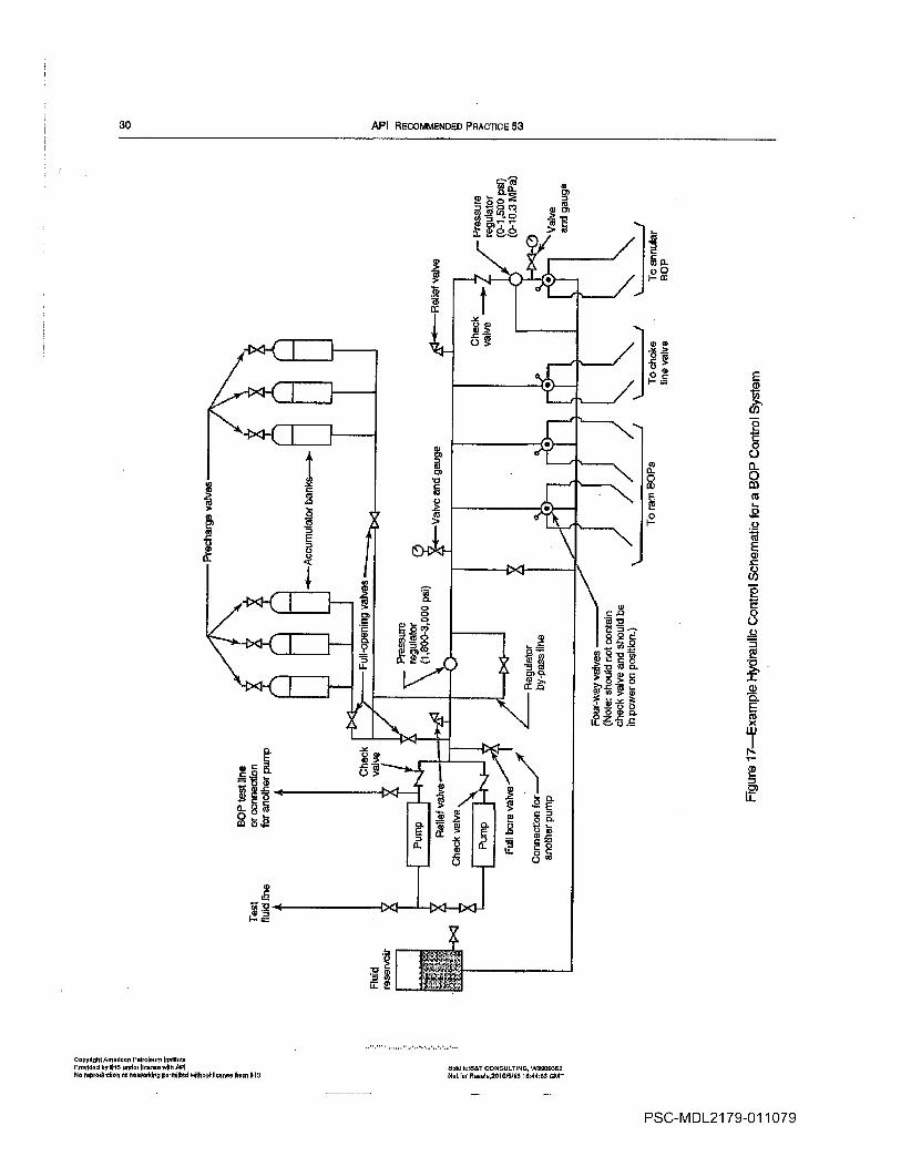
10
-u in CM
-D Ni
cc
Four-
way
valv
es
Note
should
not
conta
in
check
valv
eand
should
be
inpow
er
on
positio
n
To
ram
SO
Ps
To
ch
oke
line
valv
e
To
annula
r
BO
P
Fig
ure
17E
xam
ple
1ydru
Iic
Contr
ol
Schem
atic
for
BO
PC
ontr
ol
Syste
m
RECOMMENDED PRACTICES FOR BLOWOUT PREVENTION EQUIPMENT SYSTEMS FOR DRILLING WELLS 31
Minimum Calculated Operating Pressure The minimum
calculated pressure to effectively close and seal ram-type
flOP against welibore pressure equal to the maximum rated
working pressure of the flOP This pressure is equal to the
maximum working pressure of the SOP divided by the clos
ing ratio specified for that BOP
Component Minimum Operating Pressure Recommended
by the Manufacturer The minimum operating pressure to
effectively close and seal ram-type or annular-type preven
ter under normal operating conditions as prescribed by the
manufacturer
13.3.2 BOP systems should have sufficient usable hydrau
lie fluid volume with pumps inoperative to close and open
one annular-type preventer and all ram-type preventers from
lull-open position against zero welibore pressure After clos
ing and opening one annular preventer and all ram-type pre
venters the remaining pressure shall be 200 psi 1.38 MPa or
more above the minimum recommended precharge pressure
Note The capability of the shear rain preventer and the ram operator should be
verified with the equipment manufacturer for this planned drill string The
design of Elsa slicer ram BOP aador melattargical differences among drittpipe
manufacturers relay necessitate high closing pressureforshetw operations
13.3.3 The subsea accumulator bottle capacity calculations
should compensate hydrostatic pressure gradient at the rate of
0.445 psi per foot 0.010067 MPa per meter of water depth
For example the hydrostatic head at 500 feet 1524 meters
water depth is 222.5psi 1.54 MPg This would require that
all pressure value in this examples calculations be increased
by this amount
13.3.4 Subsea accumulators shall have isolation and dumping capabilities
1335 ACCUMULATOR RESPONSE TIME
Response time between activation and eomplctc cpcralion
of function is based on flOP or valve closurc and seal off
For subsea installations the SOP control systcm should be
capable of closing each ran SOP in 45 seconds or tess Clos
ing time should not exceed 60 seconds for annular SOPs
Operating response time for choke and kill valves either
open or close should not exceed the minimum observed ram
SOP close response time Time to unlatch the lower marinc
riser package should not exceed 45 seconds
Measurement of closing response time begins at pushing
the button or turning the control valve handle to operate the
function and ends when the BOP or valve is closed effecting
seal BC is considered closed when the regulated operat
ing pressurehas recovered to its nominal setting If confirma
tion of seal off is required pressure testing below the SOP or
across the valve is necessary
Copydglt Ameiooo Pelooleon meant
Prooldnd He undo license wild API
No epsduclloo or networking penoluedocillroul license from IHS
13.3.6 OPERATING PRESSURE
No accumulator bottle should be operated at pressure
greater than its rated working pressure
13.3.7 ACCUMULATOR PRECHARGE
The precharge pressure on each accumulator bottle should
he measured prior to each SOP stack installation on each well
and adjusted if necessary The minimum precharge pressure
for 30X psi 20.7 MPa working pressure accumulator unit
should be 1000 psi 6.9 MPa The minimum precharge pres
sure for 5000 psi 345 MPa working pressure accumula
tor unit should be 1500 psi 10.3 MPa Only nitrogen gas
should be used for accumulator precharge The precharge
pressure should be checked and adjusted to within 100 psi
0.69 MPa of the selected precharge pressure at the start of
drilling each well
For subsea accumulators the precharge pressure shall
compensate for the water depth the SOPs wilt be operating
in as described in 13.3.3 For example if the precharge prest
sure of the surface accumulators is 1000 psi 6.9 MPa and
the flOPs will be in 500 feet 152.4 meters water depth the
subsea accumulators should be precharged to 1222.5 psi
8.43 MPa
13.3.8 ACCUMULATOR VALVES FEfl1NGS ANDPRESSURE GAUGES
Multi-bottle accumulator banks should have valving for
bank isolation An isolation valve should have rated work
ing pressure at least equivalent to the designed working pres
sure of the system to which it is attached and must be in the
open position except when accumulators are isolated for ser
vicing testing or transporting
pressure gauge for measuring the accumulator precharge
pressure should be readily available for installation at any
time Pressure gauges should be calibrated to percent of full
scale at least every years
132.9 HYDRAULIC FLUID MIXING SYSTEM
The hydraulic fluid reservoir should be combination of
two or more storage sections one section containing mixed
fluid to be used in the operation of the BOPs and the other
sections containing the concentrated water-soluble hydrau
lic fluid to be mixed with water to form the mixed hydraulic
fluid This mixing system should be automntically controlled
to maintain mixed fluid ratios and levels The mixing system
should be able to mix at rate equal to the total pump sys
tems output In cold climates an extra storage section and
mixing system may be needed for glycol
noW to coplaulTiplo wugugasa
Net ioraeeale2slels/mt 164456 OMT
PSC-MDL21 79-011080

32 API RECOMMENDED PRAcTICE 53
13.4 PUMP SYSTEMS
13.4.1 Each subsea BOP control system should have
minimum of two pump systems Each pump system should
have an independent power source such as air or electric The
combination of all pump systems should be capable of
charging the accumulator system from the minimum calcu
lated operating pressure to the system maximum rated pres
sure in fifteen minutes
13.4.2 The same pump systems may be used to produce
power fluid for control of both the BOP stack and the cliverter
system
13.4.3 Each pump system should provide discharge pres
sure at least equivalent to the SOP control system working
pressur Air pumps should be capable of charging the accu
mulators to the system working pressure with 75psi 0.52
MPa minimum air pressure supply
13.4.4 Each pump system should be protected from over
pressurization by minimum of two devices to limit the
pump discharge pressure One device normally pressure
limit switch1 should limit the pump discharge pressure so that
it will not exceed the working pressureof the SOP control
system The second device normally relief valve should be
sized to relieve at flow rate at least equal to the design flow
rate of the pump systems and should be set to relieve at not
more than ten percent over the control unit pressure Devices
used to prevent pump system over pressurization should be
installed directly in the control system supply line to the accu
mulator and should not have isolation valves or any other
meansthat could defeat their intended purpose Rupture
discs.or relief valves that do not automatically reset are not
recomEnended
13.4.5 Electrical and/or air pneumatic supply for powering
pumps should be available at all times such that the pumps will
automatically start when the system pressure has decreased to
approximately 90 percent of the system working pressure and
automatically stop within plus zero or minus 100 psi 069MPa of the SOP control system working pressure
13.4.6 Separate accumulators may be provided for the pilot
control system that may be supplied by separate pump or
through check valve from the main accumulator system
The dedicated pump if used can be either air powered or
electric powered Air pumps should be capable of charging
the accumulators to the system working pressure with 75 psi
0.52 MPa minimum air pressure supply Provision should
be made to supply hydraulic fluid to the pilot accumulators
from the main accumulator system if the pilot pump becomes
inoperative
13.5 REMOTE CONTROL AND MONITORINGPANELS
13.6.1 GENERAL
The subsea SOP control system should have the capability
to control all of the SOP stack functions including pressure
regulation and monitoring of all system pressures from at
least two separate locations One location should be in npn
classified nonhazardous area as defined in API Recommended Practice 500 This may he accomplished by placing
the main hydraulic control unit in nonhazardous area
remote from the rig floor and full function remote control
panel drillers panel accessible to the driller on therig floor
In addition to the drillcrs panel and main hydraulic control
unit at least one other remote panel should be provided for
SOP stack functions
13.6 UMBILICAL CONTROL HOSE BUNDLES ANDSUBSEA ACCUMULATORS
13.6.1 Umbilical control hose bupdles provide the main
supply of power fluid and pilot signals from the surface
hydraulic coatrol manifold to the subsen control pods
mounted on the SOP stack The subsea umbilical is run
retrieved and stored on the hose reel
13.6.2 The pilot signals are routed to the hose reels through
the appropriate length of surface umbilical jumper hose bun
dle from the hydraulic connections located on the control
manifold
13.6.3 The main hydraulic power fluid supply is normally
canled through I-inch 2.54-centimeter nominal size sup
ply hose in the hose bundle to the subsea control pod An
alternative to this system is installation of rigid pipe conduit on the marine riser
13.7 HOSE REELS AND HOSE SHEAVES
13.7.1 Hose reels are used to store run and retrieve the
umbilical hose bundles that communicate the main hydraulic
power fluid supply and command pilot signals to the subsea
mounted SOP control pods The hose reels are equipped with
hose reel manifolds having valves regulators aad gauges for
maintaining control through the subsea umbilical of selected
functions during running and retrieving of the pod or lower
marine riser package and/or the SOP stack Additional hose
handling equipment includes hose sheaves used to support
and change direction of the subsea umbilical while maintain
ing the specified minimum bend radius recommended by the
umbilical manufacturer
13.7.2 All functions requircd to run land or retrieve the
lower marine riser package and/or the SOP stack should
remain fully active during landing and retrieval
Copyrightthmnrlan Petroleum lnulItue
PooIclnd by IllS undo icon olIN API
No reponluctlen oc networking pontitidwIIhocI license trero HO
611 In6T CONSULTINGW0900362Molt Role261016fl6 164466 GMT
PSC-MDL21 79-011081

RECOMMENDED PRAQTIOES FOR BLOWOUT PREVENTION EQUIPMENT SYSTEMS FOfl DRILI.JNQ WELLS 33
13.7.3 Hose sheaves shoukl facilitate running and retriev
ing the subsea umbilical from the hose reel through the
moonpool and support the ntoonpool loop which is deployed
to compensate for vessel heave
13.7.3.1 Hose sheaves should be mounted to permit
three-axis freedom of movement and prohibit damage to the
umbilical in normal ranges of anticipated movement
13.7.3.2 The hose sheave should permit installation of the
umbilical without disconnecting from the hydraulic junction
box assemblies to which the umbilical may be terminated
13.8 SUBSEA CONTROL PODS
Some systems are two BOP stack systems where the larger
stack has only one control pod However most systems are
single stack where there are two completely redundant con
trol pods on the 130 stack when drilling out from under sur
face casing Each control pod should contain all necessary
valves and regulators to operate the BOP stack functions The
control pods may be retrievable or nonretrievable The hoses
from each control pod should be connected to shuttle valve
that is connected to the function to be operated
13.9 SOP CONTROL SYSTEM VALVES FITTINGS
LINES AND MANIFOLD
13.9.1 PRESSURE RATING
All valves fittings and other components such as pressure
switches transducers transmitlers etc should have work
ing pressure at least equal to the working pressure of the con
trol system BOP control system rated working pressure is
usually 3000 psi 20.7 MPa
13.9.2 CONFORMITY OF PIPING SYSTEMS
All piping components and all threaded pipe connections
installed on the BOP control system should conform to the
design and tolerance specifications for American National
Standards Taper Pipe Threads as specified in ANSI 1.20.1
Pipe and pipe fittings should confonn to specifications of
ANSI 1131.3 If weldfittings are used the welder shall be
certified for the applicable procedure required Welding
should be performed in accordance with written weld procedure specification WIS written and qualified in accor
dance with Article II of ASME Boiler and Pressure Vessel
Code Section IX
All rigid or flexible lines between the control system and
riser should be flame retardant including end connections
and should have working pressure equal to the working
pressure of the BOP control system
All control system intercoonect piping tubing hose link
ages etc should be protected from damage during drilling
operations or day-to-day equipment movement
CnpyrIhtAmndcnn Pfrnlnm InnUtulo
Prouldod by KS undo Ilnons wIll API
rnprndndtnn or nnbnoddnn pnrrlltod niblnut Ilnonso from S-tn
13.9.3 VALVES FITI1NGS AND OTHERCOMPONENTS
The installation should be equipped with the following
The manifold should be equipped with full-bore valve
to which separate operating fluid pump can be easily
connected
The control system should be equipped to allow isolation
of both pump systems and accumulators from the manifold
and annular control circuits thus allowing maintenance and
repairs
The control system should be equipped with accurate pres
sure gauges to indicate accumulator pressure regu
lated manifold pressure annular pressure air supply
pressure manifold and annular readback pressures and
fiowmeter
The control system should be equipped with pressure
regulating valve to permit manual control of the annular pre
venter operating pressure
The control system should be equipped with regulating
valve to control the operating pressure on the ram BOPs The
control unit shnuld be equipped with bypass line and valve
to allow full accumulator pressure to be applied to the mani
fold if desired
Control valves must be clearly marked to indicate
which preventer or choke/kill valves each control valve
operates and the position of the valves i.e open closed
block or vent Each BOP control valve should be in the open
position not in the neutral position during drilling opera
tions Each choke/kill line hydraulic valve should be in the
closed position during drilling operations The control valve
that operates the blind-shear rams should be protected to
avoid unintentional operation from the remote panel without
interference
All pressure gauges on the BOP control system should be
calibrated to an accuracy percent of full scale at least every
years
13.10 CONTROL SYSTEM FLUIDS AND CAPACITY
13.10.1 CONTROL SYSTEM FLUID
suitable hydraulic fluid should be used as the closing
unit control operating fluid Sufficient volume of glycol must
be added to any closing unit fluid containing water if ambient
temperatures below 32 are anticipated
1310.2 FLUID CAPACITY
Each closing unit should have fluid reservoir with
capacity equal to at least twice the usable fluid capacity of the
accumulator system
Sold loS7 CONSULTING W590S3O2
Not for Poalo201515115 16r4450 GMT
PSC-MDL21 79-011082
34 API RECOMMENDED PAOTIQE 63
14 Electro-hydraulic and Multiplex
Control Systems for Subsea BOPStacks
14.1 GENERAL
In deep water operations hydraulic signal transmission
time is lengthened by physical expansion of the fluid conduc
tor hose as the internal pressure surges Electro-hydraulic and
multiplex control systems can be used in deep water where
response times of hydraulic signals are too lengthy Electrical
command signals transmitted over lengthy subsea cables have
shorter response times than hydraulic pilot signals transmitted
over hose bundles of equal length
Electrical command signals operate subsea solenoid valves
which in turn provide hydraulic pilot signals directly to
operate the pod valves that direct power fluid to the subsea
functions
Electro-hydraulic control systems have parallel capability
to execute and receive commands whereas multiplex control
systems process multiple signals on each conductor set Blec
tro-hydraulic systems have conductor wires in the subsea
umbilical cable dedicated to each function
Multiplex MUX systems serialize and code the command
signals that are then sent subsea via shared conductors in the
umbilical cable Multiplex control system logic may iricorpo
rate additional security by requiring verification before exe
cution of the function Subsea data are electrically transmitted
to the surface
14.2 ACCUMULATOR VOLUMETRIC CAPACITY
14.2.1 For purposes of this scction the following defini
tions apply
Stored Hydraulic Fluid The fluid volume recoverable
from the accumulator system between the maximum
designed accumulator operating pressure and the precharge
pressure
Usable Hydraulic Fluid The hydraulic fluid recoverable
from the accumulator system between the maximum accumu
lator operating pressure and 200 psi 1.38 MPa above pre
charge pressure
Minimum Calculated Operating Pressure The minimum
calculated pressure to effectively close and seal ram-type
DO against wellbore pressure equal to the maximum rated
working pressure of the flOE This pressure is equal to the
maximum working pressure of the HOP divided by the clos
ing ratio specified for that BOB
Component Minimum Operating Pressure Recommended
by the Manufacturer The minimum operating pressure to
effectively close and seal ram-type or annular-type preven
ter under normal operating conditions as prescribed by the
manufacturer
CepyrIsIiI Aoori000 PeIEeIcVm 1555mb
Provided by Il-I under license odlic API
No reprodricllo er reboorblng permllledwllhoutdrooso Iron Il-In
14.2.2 HOP systems should have sufficient usable hydrau
lic fluid volume with pumps inoperative to close and open
one annular-type preventer and all rain-type prcvcnters from
full-open position against zero wellbore pressure After clos
ing and opening one annular preventer and all ram-type pre
venters the remaining pressure shall be 200 psi 1.38 MPa or
above the minimum recommended pressure
Note The capability of the shear ram pmventer and the ram operator should
be verified with the equipment manufacturer fir the planned drillstring The
design or tile shear rans BOF and/or metatlurgical differences among drill
ptpe manuractinvrs may necessitate high closing pressure roi shear opemtions
14.2.3 The subsea accumulator bottle capacity calculations
should compensate hydmstatic pressure gradient at the rate of
0.445 psi per foot 0.010067 MPalmeter of water depth For
example the hydrostatic head at 500 feet 152.4 meters
water depth is 222.5 psi 1.54 MPa This would require that
all pressure values in this exampls calculations be increased
by this amount
14.2.4 Subsea accumulators shall have isolation and dumping capabilitics
14.2.5 Accumulator Response Tame Response time
between activation and complete opemtion of function is
based on SOP or valve closure and seal off For subsea instal
lations the BOX control system should be capable of closing
each ram BOP in 45 seconds or less Closing time should not
exceed 60 seconds for annular BOPs Operating response
time for choke and kill valves either open or close should
not exceed the minimum observed ram HOP closeresponse
time Time to unlatch the lower marine riser package should
not exceed 45 seconds
Measurement of closing response time begins at pushing
the button or turning the control valve handle to operate the
function and ends when the BOP or valve is closed effecting
seal HOP is considered closed when the regulated operat
ing pressure has recovered to its nominal setting If confirma
lion of seal off is required pressure testing below the BOP or
across the valve is necessary
14.2.6 Hydraulic Fluid Mixing System The hydraulic fluid
reservoir should he combination of two or more storage sec
tions one section containing mixed fluid to be used in the
operation of the HOPs and the other sections containing the
concentrated waler-soluble hydraulic fluid to be mixed with
water to form the mixed hydraulic fluid This mixing system
should be automatically controlled to maintain mixed fluid
ratios and levels The mixing system should be able to mix at
rate equal to the total pump systems output In cold cli
mates an extra storage section and mixing system may be
needed for glycol
Sold IoSST CONSULTING W0555352
Sos for Ileceie25I015II5 IS44nS aMy
PSC-MDL21 79-011083

RE0OMMEN0ED PnAcTIoas FOR Biowoul PREVENTION EQUIPMENT SYsTEMS FOR DRILLING WELLS 35
143 PUMP SYSTEMS
14.3.1 Each subsea BOP control system should have
minimum of two pump systems Each pump system primary
and secondary should be employed having independent
power sources such as electric air The combination of all
pump systems should be capable of charging the accumula
tor system from the minimum calculated operating pressure
to the system maximum rated pressure in fifteen minutes
14.3.2 The same pump systems may be used to produce
power fluid for control of both the flOP stack and the diverter
system
14.3.3 Each pump system should provide discharge pres
sure at least equivalent to the flOP control system working
pressure Airpumps
should be capable of charging the accu
inulators to the system working pressure with 75 psi 0.52
MPa minimum air pressure supply
14.3.4 Each pump system should be protected from over
pressurization by minimum of two devices to limit the
pump discharge pressure One device normalty pressure
limit switch should limit the pump discharge pressure so that
it will not exceed the working pressureof the flOP control
system The second device normally relief valve should be
sized to relieve at flow rate at least equal to the design flow
rate of the pump systems and should be set to relieve at not
more than ten percent over the control unit pressure Devices
used to prevent pump system over pressurization should he
installed directly in the control system supply line to the accu
mulators and should not have isolation valves or any other
means that could defeat their intended purpose Rupture
discs or relief valves that do not automatically reset are not
recommended
14.3.5 Electrical and/or air pneumatic supply for power
ing pumps should be available at all times such that the
pumps will automatically start when the system pressure has
decreased to approximately ninety percent 90 percent of the
system working pressure and automatically stop within plus
zero or minus 100 psi 0.69 MPa0 or-tOO psiof the HOPcontrol system working pressure
14.3.8 Separate accumulators maybe provided for the pilot
control system that may be supplied by separate pump or
through cheek valve from the main accumulator system
The dedicated pump if used can he either air powered or
clcclric powered Air pumps shOuld be capable of charging
the accumulators to the system working pressure with 75 psi
0.52 MPa minimum air pressure supply Provision should
he made to supply hydraulic fluid to the pilot accumulators
from the main accumulator system if the pilot pump becomes
inoperative
Ccyyrihi Americas Petroleum muScle
Provided by 185 under license mOb API
Nucnyrodtmciloro orneiworkirry penrdited wliimoui license 1mm 88
14.4 ELECTRICAL CONTROL UNIT
The electrical control unit should have central control
point corresponding to the hydrauic control manifold of
hydraulic control system Alternatively each control panel
may communicate directly and independently with each pod
14.4.1 The electrical control unit should be supplied elec
tricalpower from an uninterruptible power supply
14.4.2 The electrical control unit should be located in
safer dry area All functions should be operable from and
monitored from remote conlrol panel located on the rig
floor interfacing with the central control unit
14.4.3 The electrical control unit should maintain function
status memory in the event of power interruption Upon resto
ration of power the system should display the status of all
functions as they were prior to the loss of power
14.5 REMOTE CONTROL AND MONITORINGPANELS
The subsea flOP control system should have the capability
to control all of the BOP stack functions including pressure
regulation and monitoring of all system pressures from at
least two separate locations One location should be in non-
classified nonhazardous area as defined in API Recommended Practice 500 This may be accomplished by placing
the main hydraulic control unit in nonhazardous area
remote from therig
floor and full function remote control
panel drillers panel accessible to the driller on therig floor
In addition to the drillers panel and main hydraulic control
unit at least one other remote panel should be provided for
flop stack functions
14.6 SLJBSEA UMBILICAL CABLES ANDCONNECTORS
The subsea umbilical cable is run retrieved and stored on
cable reel The subsea umbilical electrical cable supplies
power communications and control of the aubsea control
pods The electrical conductors and electrical insulation
should not be used as load bearing components in the cable
assembly
All underwater electrical umbilical cable terminations
should be scaled to prevent water migration up the cable in
the event of connector failure or leakage and to prevent water
migration from the cable into the subsen connector terinina
tion in the event of water intrusion into the cable Individual
councetor terminations should he physically isolated so that
seawater intrusion does not cause electrical shorting pres
sure compensated junction box containing dielectric fluid
may be used to accomplish this
Amid to88T CONSULTiNG WOSQN3SZ
Not Reeio201 01858184458 GMr
PSC-MDL21 79-011084

36 API REcoMMrNcsiu Paso-non 53
14.7 SUBSEA ELECTRICAL EQUIPMENT
14.71 All electrical connections that may be exposed to
seawater should be protected to prevent overloading the sub-
sea electrical supply system in the event of water intrusion
into connections
147.2 All electrical apparatus used subsea should be tem
perature rated to be fully operational on continuous basis
while exposed to surface ambient conditions without the use
of auxiliary cooling or heating
14.7.3 All subsea electrical equipment should be suitable
for use subsea with particular attention paid to mechanical
vibration and shock induced while drilling Plugin devices
should be mechanically secured
147.4 Auxiliary subsea electrical equipment that is not
directly related to the BOP control system should be con
nected in manner to avoid disabling the SOP control system
in the event of failure in the auxiliary equipment
14.7.5 Subsea electrical equipment should be galvanically
isolated from any surface exposed to seawater
15 Auxiliary EquipmentSurface BOPInstallations
15.1
An uper kelly valve is installed between the swivel and
the kelLy lower kelly valve is installed immediately below
the kellt
15.2 DRILL PIPE SAFETY VALVE
spare drill pipe safety valve should be readily available
i.e stored in open position with wrench accessible on the
rig floor at all times This valve or valves should be equipped
to screw intoany drill string member in use The outside
diameter of the drill pipe safety valve should be suitable for
runniag into the hole
15.3 INSIDE BLOWOUT PREVENTER
An inside blowout preventer drill pipe float valve or drop-
in check valve should be available for use when stripping the
drill string into or out of the hole The valves subs or pro
file nipple should be equipped to screw into any drill string
member in use
15.4 FIELDTESTING
The kelly valves drill pipe safety valve and inside blowout
preventer should be tested in accordance with applicable rec
ommendations in Section 17
CopyIgIIAm.rI.r FoIrQIum IIiIth
Pn.vId.d by 166 Undy In. wiIb API
No roproduolier .roIw.Icing prmIItd wilboul Soon I..nr INS
15.5 DRILL STRING FLOAT VALVE
float valve is placed in the drill string to prevent upward
flow of fluid or gas inside the drill string The float valve is
special type of back pressure or check valve float valve in
good working order will prohibit backflow and potential
blowout through the drill string
The drill string float valve is usually placed in the lower
most portion of the drill string between two drill collars or
between the drill bit and drill collar Since the float valve pre
vents the drill string from being filled with fluid through the
bit as it is run into the hole the drill string must be filled from
the top at the drill floor to prevent collapse of the drill pipe
There are two types of float valves
The flapper-type float valve offers the advantage of having
an opening through the valve that is approximately the same
insidediameter as that of the tool joint This valve will permit
the passage of balls or go-devils which may be required for
operation Of tools inside the drill string below the float valve
The spring-loaded ball or dart and seat float valve offers
the advantage of an instantaneous and positive shut off of
backflow through the drill suing
These valves are not full-bore and thus cannot sustain long
duration or high volume pumping of drilling fluid or kill fluid
However wireline retrievable valve that seals in profiled
body that has an opening approximately the same inside
diameter as that of the tool joint may be used to provide
full-open access if needed
15.6 TRIPTANK
trip tank is low-volume barrels 15.9 in2 or less
calibrated tank that can be isolated from the remainder of the
surface drilling fluid system and used to accurately monitor
the amount of fluid going into or coming from the welltrip
tank may be of any shape provided the capability exists for
reading the volume contained in the tank at any liquid level
The readout may be direct or remote preferably both The
size and configuration of the tank should be such that volume
changes on the order of one-half barrel can be easily detected
by the readout arrangement Tanks containing two compart
ments with monitoring arrangements in each compartment
are prefeired as this facilitates removing or adding drilling
fluid without interrupting rig operations
Other uses of thetrip
tank include measuring drilling fluid
or water volume into the annulus when returns are lost moni
toring the hole while logging or following cement job cali
brating drilling fluid pumps etc The triptank is also used to
measure the volume of drilling fluid bled from or pumpedinto the well as pipe is stripped into or out 0f the well
Sold Io6T CONSULflNSW5559352
611 SsIe2615161 III 164456 SMr
PSC-MDL21 79-011085

REO0MMENQEO PRACTICES FOR BlowouT PREVENTION EQUIPMENT SYSTEMS RON DRILLING WELLS 31
15.7 PIT VOLUME MEASURING AND RECORDINGDEVICES
Automatic pit volume measuring devices are available
which transmit pneumatic or electric signal from sensors on
the drilling fluidpits to recorders and signaling devices on the
rig floor These are valuable in detecting fluid gain or loss
15.8 FLOW RATE SENSOR
flow rate sensor mounted in the flow line is recom
mended for early detection of formation fluid entering the
wellbore or loss of returns
15.9 MUDIGAS SEPARATOR
The mud/gas separator is used to separate gas fromdrilling
fluid that isgas cut The separated gas can then be vented to
safe distance from the rig Generally two basic types of mud
gas separators are in use The most common type is the atmo
spheric mud/gas separator sometimes referred to as gas
barter or poor-boy separator Another type of mud/gas sepa
rator is dcsigned such that it can be operated at moderate back
pressure usually less than 100 psi 0.69 MPa although some
designs are operated at gas vent linepressure
which is atmo
spheric plus line friction drop All separators with liquid
level control may be referred to as pressurized mud/gas sepa
rators Both the atmospheric and pressurized mucLgas separa
tors have advantages and disadvantages Some guidelines are
cotnmon to both types of mud/gas separators bypass line
to the flare stack must be provided in case of malfunction or
in the event the capacity of the mud/gas separator is
exceeded Precautions must also be taken to prevent erosion
at the point the drilling fluid and gas flow impinges on the
wall of the vessel Provisions must be made for easy clean out
of the vessels and lines in the event of plugging Unless spe
cificalty designed for such applications use of the rig mud/
To outlet
stripping
preventers
if
lUg
pumps
gas separator is not recommended for well production testing
operations
The dimensions of separator are critical in that they
define the volume of gas and fluid separator can effectively
handle An example of some mud/gas separator sizing
guidelines can be found in SPE Paper No 20430 Mud Gas
Separator Sizing and Evaluation G.R MacDougall
December 199t
15.10 DEGASSER
degasser may be used to remove entrained gas bubbles in
the drilling fluid that are too small to be removed by the mud/
gas separator MosE degassers make use of some degree of
vacuum to assist in removing this entrained gas Thedrilling
fluid inlet line to the degasser should he ptaced close to the
drilling fluid discharge line from the mud/gas separator to
reduce the possibility of gas breaking out of the drilling fluid
in the pit
15.11 FLARE LINES
All flare lines should be as long as practical with provi
sions for flaring during varying wind directions Flare lines
should be as straight as possible and should be securely
anchored
15.12 STAND PIPE CHOKE
An adjustable choke mounted on the rig stand pipe can be
used to bleed pressure off the drill pipe under certain condi
tions reduce the shock when breaking circulation in welts
where loss of circulation is problem and bleed offpressure
between BOPs during stripping operations Refer to Figure
IS for an example stand pipe choke installation
Flgure 18.-xampIe Startdplpa Choke Installation
CuyyrlglrlAneriuo.r Ferrolpum Institute
Provided by iHS under ticepee will dPi
No rrproduutien or eelwoekirug pererilted wiOnuLit iieneuu 1mm tHe
mold teLOTCONSUII1 NC WO9QeH2
RotNrRute20tmnlIO 16t4456CldT
Standpipe
auxllia pump _____
Cement or
access to kill
line
-fCllCAdjustable choke
Trip tank
Drilling
tluid
tanks
PSC-MDL21 79-011086
38 API RECOMMENDED PRACTICE 53
1513 TOP DRIVE EQUIPMENT
There are two ball valves sometimes referred to as kelly
valves or kelly cocks located on top drive equipment The
upper valve is air or hydraulically operated and controlled at
the drillers console The lower valve is standard ball kelly
valve sometimes referred to as safety valve and is manu
ally operated usually by means of large hexagonal wrench
Generally if it becomes necessary to prevent or stop flow
up the drill pipe during tripping operations separate drill
pipe valve should be used rather than either of the top drive
valves However flow up the drill pipe might prevent stab
bing this valve In that ease the top drive with its valves can
be used keeping in mind the following cautions
Once the top drives manual valve is installed closed and
the top drive disconnected crossover may be required to
install an inside BOP on top of the manual valve
Most top drive manual valves cannot be stripped into 751r
inch 19.37 cm or smaller casing
Once the top drives manual valve is disconnected from
the top drive another valve or spacer must be installed to take
its place
16 Auxiliary EquipmentSubsea BOPInstallations
16.1 KELLY VALVES
An upper kelly valve is installed between the swivel and
the kelly lower kelly valve is installed immediately below
the kelly
16.2 DRILL PIPE SAFETY VALVE
spare drill pipe safety valve should be readily available
i.e stored in open position with wrench accessible on the
rig floor at all times This valvc or valves should be equipped
to screw into any drill string member in use The outside
diameter of the drill pipe safety valve should be suitable for
running into the hole
16.3 INSIDE BLOWOUT PREVENTER
An inside blowout preventer drill pipe float valve or drop-
in check valve shoufd be available for use when stripping the
drill string into or out of the hole The valves subs or pro
file nipple should be equipped to screw into any drill string
member in use
16.4 FIELDTESTING
The kelly valves drill pipe safety valve and inside blowout
preventer should be tested in accordance with applicable rec
onimcadations in Section 18
Coyyrl5hlArnrloan PoIroloun InuIIIito
Prouldod by IHS udor IIono wIh API
No ropoduolloo or notookIn pormlftod wilboLd Huoooo born IHS
16.5 DRILL STRING FLOAT VALVE
float valve is placed in the drill string to prevent upward
flow of fluid or gas inside the drill string The float valve is
special type of back pressure or check valve float valve in
good working order will prohibit bnckflow and potential
blowout through the drill string
The drill string float valve is usually placed in the lower
most portion of the drill string between two drill collars or
between the drill bit and drill collar Since the float valve pre
vents the drill string from being filled with fluid through the
bit as it is run into the hole the drill string must be filled from
the top at the drill floor to prevent collapse of the drill pipe
There are twe types of float valves
The flapper-type float valve offers the advantage of having
an opening through the valve that is approximately the same
inside diameter as that of the tool joint This valve will permit
the passage of balls or go-devils which may be required for
operation of tools inside the drill string below the float valve
The spring-loaded ball or dart and seat float valve offers
the advantage of an instantaneous and positive shut off of
backflow through the drill string
These valves are not full-bore and thus oannot sustain long
duration or high volume pumping of drilling fluid or kill fluid
However wireline retrievable valve that seals in profiled
body that has an opcning approximately the same inside
diameter as that of the tool joint may be used to provide
full-open access if needed
16.6 TRIP TANK
triptank is low-volume 100 barrels 159 m3 or less
calibrated tank that can be isolated from the remainder of the
surface drilling fluid system and used to accurately monitor
the amount of fluid going into or coming from the well trip
tank may be of any shape provided the capability exists for
reading the volume contained in the tank at any liquid level
The readout may be direct or remote preferably both The
size and configuration of the tank should be such that volume
changes on the order of one-half barrel can be easily detected
by the readout arrangement Tanks containing two compart
ments with monitoring arrangements in each compartment
are preferred as this facilitates removing or adding drilling
fluid without interrupting rig operations
Other uses of the trip tank include measuring drilling fluid
or water volume into the annulus when returns are lost moni
toring the hole while logging or following cement job cali
brating drilling fluid pumps etc The trip tank is also used to
measure the volume ofdrilling
fluid bled from or pumpedinto the well as pipe is stripped into or out of the well
Sold IoSNT COPSULTINC 560505362
SOot fIooI20I045IIS 164456 SMT
PSC-MDL21 79-011087

RCCOMMENOED PRACTICES FOR BLOWOUT PREVENTION EQUIPMENT SYSTEMs FOR DRILLING WELLS 39
16.7 PiT VOLUME MEASURING AND RECORDINGDEVICES
Automaticpit
volume measuring devices are available
which transmit pneumatic or electric signal from sensors on
the drilling fluid pits to recorders and signaling devices on the
rigfloor These are valuable in detecting fluid gain or toss
16.8 FLOW RATE SENSOR
flow rate sensor mounted in the flow line is recoin-
mended for early detection of formation fluid entering the
wellbore or less of returns
16.9 MUD/GAS SEPARATOR
The mud/gas separator is used to separate gas from drilling
fluid that is gas cut The separated gas can then be vented to
safe distance from the rig Generally two basic types of mud/
gas separators are in use The most common type is the atmo
spheric mudlgas separator sometimes referred to as gas
buster or poor-boy separator Another type of mud/gas sepa
rator is designed such that it can be operated at moderate back
pressure usually less than 100 psi 0.69 MPa although some
designs are operated at gas vent linepressure which is atmo
spheric plus line friction drop All separators with liquid
level control may be referred to as pressurized mud/gas sepa
rators Both the atmospheric and pressurized mud/gas separa
tors have advantages and disadvantagos Some guidelines are
common to both types of mud/gas separators bypass line
to the flare stack must be provided in case of malfunction or
in the event the capacity of the mud/gas separator is
exceeded Precautions must also he taken to prevent erosion
at the point the drilling fluid and gas flow impinges on the
wall of the vessel Provisions must be made for easy clean out
of the vessels and lines in the event of plugging Unless spe
cifically designed for such applications use of the rig mud/
gas separator is not recommended for well production testing
operations
The dimensions of separator are critical in that they
detine the volume of gas and fluid separator can effec
tively handle An example of some mud/gas separator sizing
guidelines can be found in SPE Paper No 20430 Mud Gas
Separator Sizing and Evaluation OR Macflougall
December 1991
16.10 DEGASSER
degasser may be used to remove entrained gas bubbles in
thedrilling
fluid that are too small to be removed by the mud
gas separator Most degassers make use of some degree of
vacuum to assist in removing this entrained gas The drilling
fluid inlet line to the degasser should be placed close to the
drillingfluid discharge line from the mud/gas separator to
reduce the possibility of gas breaking out of the drilling fluid
in the pit
16.11 FLARE LINES
All flare lines should be as long as practical with provi
sions for flaring during varying wind directions Rare lines
should be as straight as possible and should be securely
anchored
16.12 STAND P1PE CHOKE
An adjustable choke mounted on therig stand pipe can be
used to bleed pressure off the drill pipe under certain condi
tions reduce the shock when breaking circulation in wells
where loss of circulation is problem and bleed offpressure
between BOPs during stripping operations Refer to Figure
18 for an example stand pipe choke installation
16.13 TOP DRIVE EQUIPMENT
There are two ball valves sometimes referred to as kelly
valves or /celly cocks located on top drive equipment The
upper valve is air or hydraulically operated and controlled at
the drillers console The lower valve is standard ball kelly
valve sometimes referred to as safety valve and is manually operated usually by means of large hexagonal wrench
Generally if it becomes necessary to prevent or stop flow
up the drill pipe during tripping operations separate drill
pipe valve should be used rather than either of the top drive
valves However flow up the drill pipe might prevent stab
bing this valve In that case the top drive with its valves can
be used keeping in mind the following cautions
Once the top drives manual valve is installed closed and
the top drive disconnected crossover may be required to
install an inside flOP on top of the manual valve
Most top drive manual valves cannot be stripped into 754inch 19.37 cm or smaller casing
Once the top drives manual valve is disconnected from
the top drive another valve or spacer must be installed to take
its place
16.14 GUIDE FRAMES
The flOP guide frame four-post structure attached to the
flOP assembly is means for guiding the complete BOP/
LMRP assemblys primary alignment onto the permanent
guide base refer to API Specification 17D The upper sec
tion of the guide structure acts as primary guidance for the
lower marine riser package The guide structure also acts as
the structural mounting for the various components of the
remote control system and the choke/kill connectors or stab
subs The guide structure should have sufficient strength to
protect the flOP stack from damage during handling and
landing operations
Copyright Arnedoan Pooolouot irniltuTo
Prooitd by IHS undo Iloono wIth dPi
lb reproduolion or ntwoblog prormillod without hones born IRS
Sold loSbT CONSULTING W09003S2Not for Renole25i015/iO 104450 GNT
PSC-MDL21 79-011088
40 API RECOMMEuDED PRACTICE 53
16.15 UNDERWATER TELEVISION
An underwater television system for visual inspection of
the welihead BOP stack marine riser and other allied under
water components generally consists of television camera
and high intensity lights attached to telescoping guide
frame This guide frame normally attaches around two of the
guidelines The assembly can be lowered and retrieved by
special umbilical cable that supports the package plus fur
nishes all electrical circuitry for the television camera and
lights Surface equipment includes powered reel for the
umbilical cable and television monitor with allied electronic
equipment and camera remote control
16.16 SLOPE INDICATOR
This device is circular glycerin- filled plexiglas-covered
slope indicator used to measure the angular deflection of
components to which it is attached chrome plated ball
bearing inàide the slope indicator moves about circular black
and white bands graduated in degreespainted on the base
to indicate angular position Slope indicators are typically
installed on the permanent guide base BOP guide frame
LMRP guide frame and first joint of riser above the lower
ball/flex joint
16.11 PIN CONNECTOR/HYDRAULIC LATCH
This hydraulically operated connector is used to connect
the drilling riser to the conductor housing before the BOPstack is run to allow returns back to the surface This assern
bly can also be used in conjunction with subsea diverter
application
16.18 MUD BOOSTER LINE
Some riser strings are equipped with mud booster line
This is an additional auxiliary line used to increase volume
and flow rate of drilling fluid up the riser and to allow circu
lating the riser above shut in SOP stack Booster lines nor
mally terminate into the riser just above the lower flex/ball
joint on the LMRP
16.19 AUXILIARY HYDRAULIC SUPPLY LINE
HARD/RIGID CONDUIT
An auxiliary hydraulic supply line referred as hard or
rigid conduit is metallic line attached to risers joints The
purpose of this auxiliary line is to supply control fluid from the
surface accumulator system to the control pods and subsea
accumulators mounted on the BOP and/or LMRP assemblies
1620 RISER TENSIONING SUPPORT RING
riser tensioning support ring is attached integrally or
remotely to the telescopic joint outer barrel to allow tension
ing of the riser The tensioning ring Is the mechanical link
Copyright Amorloen Iolooloum InotlIolo
PrwoIdd by Il-IS under Ilnn wIth API
ide noyrodonrino or oulwerWrg ynnrrdyed ydihoot loot mom Il-IS
between the riser and the tensioner cables on the rig The riser
tensioners allow relative movement of the drilling vessel with
respect to the stationary riser
17 Testing and MaintenanceSurfaceBOP Stacks and Well Control
Equipment
17.1 PURPOSE
The purposes for various field test programs on drilling
well control equipment are to verify
That specific functions are operationally ready
The pressure integrity of the installed equipment
The control system and BOP compatibility
172 TYPES OFTESTS
Test programs incorporate visual inspections functional
operations pressure tests maintenance practices and drills
For purposes of this document the following definitions are
used for the basic types of tests
17.21 INSPECTION TEST
The common collective term used to state the various procedural examination of flaws that may influence equipment
performance These inspection tests may include but are not
limited to visual dimensional audible hardness functional
and pressure tests Inspection practices and procedures vary
and are outside thescope of this document An example of
some inspection guidelines can be found in IADC/SPE Paper
23900 Field Guide for Surface BOP Equipment Inspec
ricing Kandel and Streu February 1992
17.2.2 FUNCTION TEST
The operation of piece of equipment or system to verif
its intended operation Function testing typically does not
include pressure testing Actuation test operating test and
readiness test are other terms commonly used synonymously
for function test
17.2.3 PRESSURE TEST
Periodic application of pressure to piece of equipment or
system to verify the pressure containment capability for the
equipment or system Wellbore test is another descriptive
term frequently used synonymously for pressure test
17.2.4 HYDRAULIC OPERATORTEST
The application of pressure test to any hydraulic operated
component of hydraulic-actuated equipment Hydraulic oper
ator tests are typically specified by the manufacturer for such
items as BOP operator cylinders and bonnet assemblies
Sold loAT CONSULTING 5t5SSU2
Nut to Nooolo251015116 164456 GMT
PSC-MDL21 79-011089
RECOMMENDED PRACTICES FOR BLOWOUT PREVENTION EQUIPMENT SYSTEMS FOR DRILLING WELLS 41
hydraulic valve actuators hydraulic connectors etc Operat
lag chamber test is frequently used synonymously for
hydraulic operator test
Note The definitions of test pressure design pressure operational character
istic tests etc as used in outer API documents may have meaning/intent
more appropriate to manufacturing processes and the intended description
may difkr with field usage
Site-specific applications of the different types of tests on
well control equipment should be incorporated during field
acceptance tests initial rig-up tests drills periodic operating
tests maintenance practices and drilling operations
Note Thchniques and step-by-step or how-to-testprocedures
should be
developed for each rig because of the vsiyisg equipment different installa
tionarrangements
and welt-specific drilling programs The procedttte for
testing the flOP stack drill string safety valves chokr/kill lines and mani
fold upstream of the buffer chamber are usually similar far roost rigs Ptea
sure test programs fur Ihe wcllheod and casing should be prescribed by the
operator on an ladivlduat welt basis Manufactuser operating and mainte
nance documents contractor maintenance programs andoperating experi
ences should beiacorposnled
into thespecific test procedures
17.2.5 CREW DRILLS
The proficiency with which drilling crews operate the well
control equipment is as significantly important as the opera
tional condition of the equipment Crew drills and well con
trol rig practices are outside the scope of this document and
are addressed in API Recommended Practice 59
17.3 TEST CRITERIA
173.1 FUNCTiON TESTS
All operational components of the SOP equipment sys
tems should be functioned at least once week to verify the
components intended operations Function tests may or may
not include pressure tests
Function tests should be alienated from the drillers
panel and from mini-remote panels if on location
Refer to worksheets in Appendix
Actuation times should be recorded as data base for
evaluating trends Refer to worksheets in Appendix
17.3.2 PRESSURE TESTS
17.3.2.1 All blowout prevention components that may be
exposed to well pressure should be tested first to tow pres
sure of 200 to 300 psi 138 to 2.1 MPa and then to high
pressure
When performing the low pressure test do not apply
higher pressure and bleed down to the low test pres
pure The higher pressure could initiate seal that mayontinue to seal after the pressure is lowered and there
fore misrepresenting low pressure condition
stable low test pressure should be maintained for at
east mismtes
copyilglt Amadoan PIrnluw hItut
Proldd by He uid.r linen will API
17.32.2 The initial high pressure test on components that
could be exposed to well pressure 110 stack choke mani
fold and choke/kill tines should be to the rated working
pressure of the ram SOPs or to the rated working pressure of
the wellhead that the stack is installed on whichever is lower
Initial pressure tests are defined as those tests that should be
performed on location before the well is spudded or before
the equipment is put into operational service
Diverter systems are typically pressure tested to low
pressure only refer to API Recommended Practice 64Annular SOPs with joint of drill pipe installed may
be tested to the test pressure applied to the ram BOPs or
to minimum of 70 percent of the annular preventer
working pressure whichever is the lesser
The lower kelly valves kelly kelly cock drill pipe
safety valves inside 301s and top drive safety valves
should be tested with water pressure applied from
below to low pressure of 200-300 psi 1.38 to 2.1
MPa then to the rated working pressure
There may be instances when the available BOP stack
and/or the weilbead have higher working pressures than
are required for the specific wellbore conditions due to
equipment availability Special conditions such as these
should be covered in the site-specific well control pres
sure test program
17.3.2.3 Subsequent high pressure tests on the well control
components should be to pressure greater than the tslani
mum anticipated surfnee pressure but not to exceed the work
ing pressure of the ram BOPs The maximum anticipated
surface pressure should be determined by the operator based
on specific anticipated welt conditions
Annular 1301s with joint of drill pipe installed should
be tested to minimum of 70 percent of their working pres
sure or to the test pressure of the ram SOPs whichever is
less Subsequent pressure tests are tests that should be per
formed at identified periods during drilling and completion
activity on wall
stable high test pressure should be maintained for at
least minutes With larger size annular SOPs some
small movement typically continues within the large
rubber mass for prolonged periods after pressure is
applied This packer creep movement should be con
sidered when monitoring the pressure test of the
annular
Pressure test operations should be alternately controlled
from the various control stations
17.3.2.4 The pressure test performed on hydraulic
chambers of annular SOPs should be to at least 1500 psi
10.3 MPa Initial pressure tests on hydraulic chambers of
ram BOPs and hydraulically operated valves should be to
the maximum operating pressure recommended by the
manufacturer
Sold loST CO1dSULTING WIIHOH3H2
Hal Is RaIn201 515/Is 54455 CMI
PSC-MDL21 79-011090

42 API RECOMMENDED PRACTICE 53
The tests should be run on both the opening and the
closing chambers
Pressure should be stabilized for at least minutes
Subsequent pressure tests are typically performed on
hydraulic chambers only between wells or when the equip
ment is reassembled
17.3.2.5 The initial pressure test ott the closing unit valves
manifolds gauges and BOP hydraulic control tines should be
to the rated working pressureof the control unit Subsequent
pressure tests of closing unit systems are typically performed
following the disconnection or repair of any operating pres
sure containment seal in the closing unit system but limited
to the affected component
17.3.3 PRESSURE TEST FREQUENCY
Pressure tests on the well control equipment should be con
ducted at least
Prior to spud or upon installation
After the disconnection or repair of any pressure contain
meni seal in the SOP stack choke line or choke manifold
but limited to the affected component
Nat to exceed 21 days
17.3.4 SUMMARY
Tables and inŁlucte summary of the recommended test
practices for surface BOP stacks and related well control
equipment
11.3.5 TEST FLUIDS
Well control equipment should be pressure tested with
water Air should be removed from the system before test
pressure is applied Control systems and hydraulic chambers
should be tested using clean control systemfluids with lubric
ity and corrosion additives for the intended service and oper
ating temperatures
17.3.6 PRESSURE GAUGES
Pressure gaugesand chart recorders should be used and all
testing results recorded Pressurc measurements should be
made at not less than 25 percent nor more than 75 percent of
the full pressure span of the gauge
17.3.7 TEST DOCUMENTATION
The results of nil SlOP equipment pressure and function
tests shall be documented and include as minimum the
Oepy.lghtAme.icun PeIrdeum lnlitule
ProvIded by INS under license wIll API
Ida reprodunllore ornelworkIng permilled wItlinol llcnne rem INS
testing sequence the low and high test pressures the duration
of each test and the results of the respective component tests
Pressure tests shall be performed withpressure chart
recorder or equivalent data acquisition system and
signed by pump operator contractors tool pusher and
operating company represeatative
Problems observed during testing and any actions taken
to remedy the problems should be documented
Manufacturers should be informed of well control
equipment that fails to perform in the field Refer to
API Specification lóA
17.3.8 GENERAL TESTING CONSIDERATIONS
Rig crews should be alerted when pressure test operations
are to be conducted and when testing operations are under
way Only necessary personnel should remain in the test area
Only personnel authorized by the well sitc supervisor
should go into the test area to inspect for leaks when
the equipment involved is under pressure
Tightening repair or any other work is to be done only
after pressure has been released and all parties have
agreed that there is no possibility of pressure being
trapped
Pressure should be released only through pressure-
release lines
All lines and connections that are used in the test proce
dures should be adequately secured
All fittings connections and piping used in pressure
testing operations shall have pressure ratings greater
than tbe maximum anticipated test prdssure
Verify the type pressure rating size and end connections
for each piece of equipment to be tested as documented by
permanent markings on the equipment or by records that are
traceable to the equipment
When BOP stack is tested on the wellhead procedure
should be available to monitor pressure on the casing should
the test plug leak
If the control system regulator circuit is equipped with
hydro-pneumatic regulators backup supply is recom
mended to pilotthe regulators in case the
rigair supply is lost
Functional tests of the control system should include simu
lated loss of power to the control unit and to the control panel
Vertical stack alignment should be checked and flange bolt
make-up should be toqued to prescribed ratings established
in API Specification 6A
If hydrogen sulfide hearing formations are anticipated
manufacturers certification for compliance with NACE Stan
dard MRO 175 should be available and reviewed for well con
trol equipment as described in Section 20
Sold 10061 CONSULTING WOOl 0362
Nd RonIe251Q5dI6 164456 I3MT
PSC-MDL21 79-011091

RECOMMENDED PRACTIcES von BLOWOUT PREVENTION EQUIPMENT SYSTEMS FOR DRILLING WELLS 42
Table 1Recommended Pressure Test Practices L.and and Bottom-Supported Rigs
Initial Test prior to spud or upon installation
Reeomtnended Pressure Test Recommended Pressure Test
Component to be Tested Low Pressure ps High Pressure psP
Rotating Head 200-3001.38 -2.1 MPa Optional
Diverter Element Minimum of 2001.38 MPa Optional
Annular Preventer 200-301 1.38 2.1 MPa Minimum of 70% of annular SOP working
pressure
Opersting Chumbem N/A Minimum of 150010.3 MPa
Ram Preventers
FixedPipe 200-300138 2.1 MPa Working pressure
of ram SOPs
Variable Bore 200-3001.38 2.1 MPa Working pressure of ram flOPs
Blind/Blind Shear 200-300 1.38- 2.1 MPa Working pressure of mm SON
Operating Chamber N/A Maximum opemring pressure recommended by
rare SOP snanssfaeturer
Diveeter Flcswlines flow Test N1A
Choke Line Valves 200-3001.38 -2.1 MPa Working presaure of ram flOPs
Kill Line Valves 200-3001.38 -2.1 MPa Working pressureof stun SOPs
Choke Manifold
Upstream ol Last High
Pressure Valve 200-300 1.38 2.1 MPa Working pressureof ram SOPs
Downstream of Lost High
Pressure Valve 200-300138 2.1 MPs Optional
POP Control System
Manifold and SOP Lines N/A Mini mu us 01300020.7 MPaAccumulator Pressure Verify Prechtsrge N/A
Close Time Function test N/A
Pump Capability Funotion test N/A
Control Slntions Function test N/A
tO Safety Valves
Kelly Kelly Valves ond Floor
Safely Valves 200-300 1.38 2.1 Pa Working pressure of coosponeat
II Auxiliary Equipment
Mud/Gus Separator Flew Teat N/A
Trip tank Ho-Show
etc flow Test N/A
eThe lowpressure test should be stable for at lesst minutes
liThe high pressure lest shoald be stable for at least minutes Flow-type tests should be of sufficient duration to observe for aigniticant leaks
The rig available welt control equipment sony have Isigher rated workisg pressure than site required The site-specific test sequtremeot should he considered
for these situations
ecpydthtAmeetcen Petroleum tsnttvto
Provided by 155 undenliceene wilt API Sold In5T CONSOLIINS yruStyabs
so reproduction oneetwerblng rcr.nsted sdtheut licence teem 55 Net for Rnuoio25t5/5u1S 164456 CMI
PSC-MDL21 79-011092
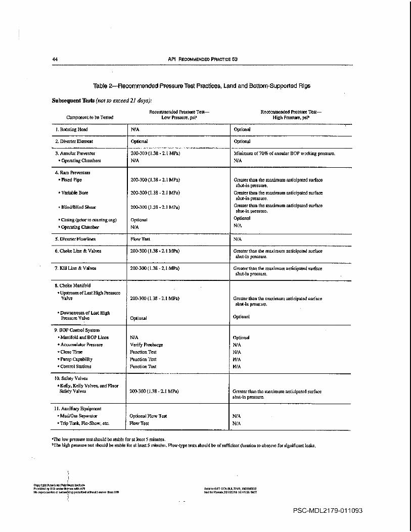
44 API RE0OMMENDED PRAcToE 53
Table 2Recommended Pressure Test Practices LRncI and cttom-Supported Rigs
Subsequent Tests no to exceed 21 days
Recommended Pressure Test Recommended Pressure Test
Component to be Tested Low Pressure psi High Pressure psi5
Rotating Head N/A Optional
Diverter ElementOptional Optional
Annular Preventer 200-300138 2.1 MPa Minimum 070% of annular SOP working pressure
Opemting Chambers N/A N/A
Rant Preventers
Fixed Pipe 200.300 1.38W 2.1 MPa Greater thaa the maximum anticipated surface
shut-in pressure
Variable Born 200-300 1.38 2.1 MPa Greater than the maximum anticipated surface
shut-in pressure
Blind/Blind Shear 200-300 1.38 .- 2.1 MPa Greater than she maximum anticipated surface
shut-sn pressure
Casing prior torusining esg Optional
Optional
Operating Chamber N/A N/A
Diverter Floarlines Flow Test N/A
Choke Line Valves 200-300 1.38 MPa Greater than the maximum anticipated surface
shut-in pressure
Kill Line Vatves 200-3001.38 2.1 MPa Greater than the maximum anticipated surface
shut-in pressure
Choke Manifold
Upstrcansof Last High Pressure
Valve 200-3001.38 2.1 MPa Greater than The maximum anticipated surface
shut-in pressure
Downstream of Last High
Pressure Valve OptioisalOptional
SOt Control System
Manifold sod SOP Lines N/A Optional
Accumulator Pressure Verify Preeharge N/A
Close Time Function Test N/A
Pump Capability Function Test N/A
Control Stations Function Test N/A
tO Safety Valves
Kelly Kelly Valves and Floor
Safety Valves 200-300 1.38 2.1 MPa Greater than the maximum anticipated surface
shut-Inpressure
ttAuxiliary Equipment
Mud/Gsa Separator Optional Plow Tsst N/A
Trip Tank Plo-Show etc flow Test N/A
The lowpressure test should be stable for nt least minutes
5Ths high pressuretest should be stable for at toastS snlnutes Plow-type tests should be of sufficIent duration to observe for eignificant leaks
CopyriglilArnerlusrr Petroleum InoStulu
Provided b5 INS under srinue also API sold ro551 CONsuLTING W0900302
No reproduction or nerwotirlrrp permisod wilhororlleonue sour ins Nor luroonaleTOl sf6/is 104455 DM1
PSC-MDL21 79-011093
RECOMMENDED PRACTICES FOR BLowouT PREVENTION EQUIPMENT SYSTEMs FOR DRILLING WeLts 45
17.4 DIVERTER SYSTEM
17.4.1 INSTALLATION TEST
All diverter system components shall be inspected and
tested to ascertain proper installation and functioning Simu
late loss ofrig
air supply to the diverter control system and
determine effects if any on the diverter system vent line
valves and backup supply systems The inspections and tests
should include but not be limited to
Check and verify the proper structural mounting of the
annular sealing device assembly and if applicable that the
insert packing element is secured in place
For installations using remote operators record hydraulic
pressure and air supply pressure with the accumulator fully
charged and the controls in the normal drilling position
Actuate the diverter close and open sequence with drill
pipe or test mandrel in the diverter to verify control functions
proper equipment operating sequence and interlock if appli
cable and record response times
pressure integrity test psi 1.38 MPa minimum
should be made on the diverter system after each installation
The tests may be made on parts of the system or on individual
components of the system should certain components of the
casing string or riser components not support complete sys
tern test
Pump water or drilling fluid through the diverter system at
low pressure and high flow rates and check vent lines for
returns Examine the entire system for leaks excessive vibra
tions and proper tie down while pumping fluid at high rates
In cold climates the diverter vent lines shall be protected
from freezing Possible methods include flushing with anti
freeze solution draining insulation and heat tracing
17.4.2 SUBSEQUENT EQUIPMENT FUNCTIONTEST
When in primary diverter service no hOP installed tune-
lion tests should be performed on the diverter system at
appropriate times using the drillers panel to verify that func
tiàns are operable Fluid should be pumped through each
dLverter vent line at appropriate times during operations to
esure that lines are not plugged
Nbtes
Jibe low pressure test shouLd be stable for at tesst lIve mInutes
Mow-type loots should be sufficient to determine if leaks exist
The sigs available well control equipment may have higher rated work
ia pressure than required Site specific test reqsstresneuts should be consid
ered in these situations
17.5 SURFACE BOP STACK EQUIPMENT
17.5.1 For the purpose of this section the surface DOstack equipment includes the wetlbore pressure containing
equipment above the wellhead including the ram BOPs
CopylghtAmetur Petroleum Iitlulu
Provided by IHS under liven with API
Ito reproduction or vetwuklng permItted without lIcence Iron Ills
spools annulars choke and kill valves and choke line to
the choke manifold Equipment above the uppermost DO is
not included
17.5.2 Unless restricted by height the entire stack should
be pressure tested as unit
17.5.3 Annular BOPs should be tested with the smallest
OD pipe to be used
175.4 Fixed bore pipe rams should be tested only on the
pipe OlD size that matches the installed pipe ram blocks
17.5.5 Variable bore rams should be initially pressure
tested on the largest and smallest OlD pipe sizes that may be
used during the well operations
17.5.6 Blind ram flOPs and blind shear ram BOPs should
not be tested when pipe is in the stack The capability of the
shear ram and ram operator should be verified with the DOmanufacturer for the planned drill string The shear ram and
preventer design nndlor metallurgical differences among drill
pipe manufacturers may require high closing pressures for
shear operations
17.5.7 Prior to testing each ram DO the secondary rod
seals emergency packoff assemblies should be checked to
ensure the seals have not been energized Should the ram
shaft seal leak during the test the seal shall be repaired rather
than energizing the secondary packing
17.5.8 Ram BOPs equipped with rain tocks should be pres
sure tested with ram locks in the closed position and closing
pressure bled to zero Manual locks either screw clockwise or
counter-clockwise to hold the rams closed Hand wheels
should be in place and the threads on the ram locking shaft
should be in condition that allows the locks to be easily
operated
17.5.9 The BOP elastomeric components that may be
exposed to well fluids should be verified by the flOP manufacturer as appropriate for the drilling fluids to be used and
for the anticipated temperatures to which exposed Consider
ation should be given to the temperature and fluid conditions
during well testing and completion operations
17.5.9.1 Manufacturers markings for hOP elastomeric
components should include the durometer hardness generic
type of compound date of manufacture pan number and
operating temperature range of the component
17.5.9.2 Consider replacing critical flOP elastomeric com
ponents on well control equipment that has been out of ser
vice for six months or longer
17.5.10 Flexible choke and kitl lines should be tested to
the same pressure frequency antI duration as the ram flOPs
Sold trOT cONsULTING WG55536It
Met lou Revnte2010stlt tsrd456 GkIT
PSC-MDL21 79-011094

46 API RECOMMENDED PnACTIcE 53
17.5.11 Verify that properly precharged surge bottle is or
can be installed adjacent to the annular preventer if contin
gency well control procedures include stripping operations
17.5.12 The drill pipe test joint and casing ram test sub
should be constructed of pipe that can withstand the tensile
collapse and internal pressures that will be placed on them
during testing operations
17.6 CHOKES AND CHOKE MANIFOLDS
17.6.1 The choke manifold upstream of and including the
last high pressure valves refer to Figure shpuld ho tested
to the same pressure as the rant BOPs
17.6.2 The configuration of pipes and valves downstream
of the last high pressure valve varies from installation to
installation Bach configuration should be verified for
mechanical integrity
17.6.3 The valves and adjustable chokes should be oper
ated to verify smooth operation
17.6.4 Adjustable chokes are not required to be full sealing
devices Pressure testing against closed choke is not
required
17.7 ACCUMULATOR SYSTEM
17.7.1 ACCUMULATOR CLOSING TEST
The purpose of this test is to verify that the accumulator
system is property sized to support the fluid volume and pres
sure requirements of the BOPs on the rig This test should be
performed after the initial nipple up of the BOPs and prior to
each subsequent pressure test using the following procedure
Refer to sample worksheets and examples in Appendix
Position properly sized joint of drill pipe or test mandrel in the HOPs
Thrn off the power supply to all accumulator charging
pumps air electric etc.
Record the initial accumulator pressure The initial accu
mulatorpressure should be the designed operating pressure of
the accumulator Manifold and annular regulators should be
set at the manufacturers recommended operating pressure for
the BOP stack
Individually close each rem BOP excepting blind or
blind/shear ram HOPs and record the closing time To simu
late closure of the blind or blind/shear rams open one set of
the pipe rams Closing times shall meet the response times
stipulated in 12.3.2
Function the hydraulic operated valves and record the
time and volume required
Close the annular HOP and record the closing time
Copyright Ansorleuts Poiraleum InsIilssle
Provided by IllS tinder license ntis dPi
reproduction or nelwesirieg permitted vdihotiu livers from Il-fm
Record the final accumulator pressure The final accumu
lator pressure shall be equal to or greater than 200psi 1.8
MPa above precharge pressure
17.8 AUXILIARY EQUIPMENT
Auxiliary equipment includes the upper and lower kelly
valves drill pipe safety valves inside BOPs and kelly
17.8.1 Prior to spud or initial use determine from the manufacturer5s documentation whether kelly cocks and safety
valves can be opened when rated working pressure below the
valve is equalized by applying pressure from the top
17.8.2 Verify that appropriate operating tools wrenches
etc are readily available
17.9 MUDIGAS SEPARATOR
Prior to spud pump water or drilling fluid into the separa
tor inlet and verify unobstructed flow from the separator or
connections If the separator is equipped with float to regu
late liquid discharge observe that the floatproperly regulates
liquid discharge
17.10 INSPECTIONS
17.1 0.1 BETWEEN WELLS
After each well the well control equipment should be
cleancd visually inspected preventative maintenance per-
fanned and pressure tested before installation on the next
well The manufacturers test procedures as prescribed in
their installation operation and maintenance TOM manual
should he followed along with the test recommendations of
Table All leaks and malfunctions should be coffected prior
to placing the equipment in service
17.1 0.2 VISUAL INSPECTIONFLEXIBLE CHOKEAND KILL LNES
visual external inspection of flexible choke and kill lines
through the entire length of the line should include
Outer Jacket Visually inspect to ensure that the outer
jacket is intact to protect the polymeric sheath underneath
from tearing and being punctured
Verify that the outer jacket is properly attached at both
end fittings
Verify that the entire surface of the polymeric sheath is
protected
If any damage is noticed on the outer jacket verify that
it will not he detrimental to the polymeric sheath
Termination Record any damage to the coating on the
end-fitting and monitor progression of damage Facilitate
repair ifnecessary
Soid InST CONSULTiNGW0659362i-tot
Inc tlosoI25 15/5116 1445N 3111
PSC-MDL21 79-011095
RECOMMENDED PRA0TIOES FOR BLOWOUT PREVENTION EQUIPMENT SYSTEMS FOR DRILLING WELLS 41
Connector Particularly inspect the seal area of the con-
Rectors recording any damage and monitor progression of
damage
17.10.3 MAJOR INSPECTIONS
After every 3-5 years of service the BOP stack choke mani
fold and diVerter components should be disassembled and
inspected in accordance with the manufacturers guidelines
Elastomeric components should be changed out and sur
face finishes should be examined for wear and corrosion
Critical dimensions should be checked against the manufac
turers allowable wear limits Individual components can be
inspected on staggered schedule
full internal and external inspection of the flexible choke
and kill lines should be performed in accordance with the
equipment manufacturers guidelines
17.11 MAINTENANCE
17.lli INSTALLATION OPERATION ANDMAINTENANCE MANUALS
Manufacturers installation operation and maintenance
IOM manuals should be available on the rig for all the BOP
equipment installed on the rig
17.11.2 CONNECTIONS
Studs and nuts should be checked for proper size and
grade Using the appropriate lubricant torque should be
applied in eriss-cross manner to the flange studs All bolts
should then be rechecked for proper torque as prcscrihcd in
API Specification 6A When making up connections exces
sive force should not be required to bring the connections into
alignment
Ring gaskets coated with resilient material such as rubber
or polytetrafluoroethylene PTPE should not he used Due to
the limited amount of deformation which groove can make
in ring as it is compressed during installation it is not rec
ommehded to reuse ring gaskets
Whön making up proprietary clamp hubbed connections the
manufacturers recommended procedure should be followed
17.113 REPLACEMENT PARTS
Spare parts should be designed for their intended use by
industry approved and accepted practices After spare part
installation the affected pressure-containing equipment shall
be pressure tested Elastomeric components shall be stored in
manner recommended by the equipment manufacturer
The original equipment manufacturer should be consulted
regarding replacement parts If replacement parts are
acquired from nonoriginal equipment manufacturer the
parts shall be equivalent to or superior to the original equip-
ment andfully tested design verified and supported by trace
able documentation
17.11.4 TORQUE REQUIREMENTS
Manuals or bulletins containing torque specifications
should be available on the rig As stated in 17.11.2 torque
specifications and the lubricants coefficient of friction should
be considered when torqiting fasteners Deviating from the
specified lubricant can alter the required torque
17.11.5 EQUIPMENT STORAGE
When BOP is taken out of service for an extended period
of time it should be completely washed steam cleaned and
machined surfaces coated with corrosion inhibitor The
rams or scaling element should be removed and the internals
washed iaspected and coated with corrosion inhibitor
Connections should be covered with corrosion inhibitor and
protected with wooden or plastic covers The hydraulic oper
ating chambers should be flushed with corrosion inhibitor
and hydraulic connections plugged For cold climates pre
cautions should be taken to prevent damage The equipmentshould be elevated to prevent it from standing in water The
original equipment manufacturer should be consulted for any
further specific details
17.11.6 LUBRICANTS AND HYDRAULIC FLUIDS
The original equipment manufacturer should hc consulted
for the proper lubricants and control fluids to be used On sur
face applications light mineral based hydraulic fluid can be
used In offshore operations mixture of potable water and
water soluble oil specifically formulated for this purpose is
frequently used Diesel fuel kerosene drilling fluid and salt
water shall not be used in FOP hydraulic control system
refer to 16.1
17.11.7 WELD REPAIRS
Weld repairs on pressure containing and load bearing coin
ponents shall only be performed in accordance with API
Specification 6A API Specification 6A manufacturers
standards or other applicable standards
All welding of weilbore pressure containing components
shall comply with the welding requirements of NACE Stan
dard MROI 75 Verification of compliance shall be established
through the implementation of the repairers written weld
procedure specification WPS and the supporting procedure
qualification PQR Welding shall he performed in accor
dance with WPS written and qualified in accordance with
Article II of ASME Bailer and Pressure Vessel Code Section
IX The original equipment manufacturer should be consulted
to verify proposed weld procedures
CopydoblAmorlo Psoloom Inaillulo
ProvIded by INS tudor boost otto AvI
No reproductIon nolwoildug peerrlttod wIllioul lIcense boom Il-IS
Sold toSr CONSULTING W0500362
Not for RooIoSSIEISiIS d4455 aNT
PSC-MDL21 79-011096
48 API RECOMMENDED PfIACT1OE 53
Field welding shall not be performed on flexible lines or
end connections without prior consultation with the original
equipment manufacturer
17.11.8 MUDIGAS SEPARATOR INSPECTION ANDMAINTENANCE
The rig maintenance and inspection schedule should pro
vide for periodic nondestructive examination of the mud/gas
separator to verify pressure integrity This examination maybe performed by hydrostatic ultrasonic or other examination
methods
11.12 QUALITY MANAGEMENT
11.12.1 PLANNED MAINTENANCE PROGRAM
ptanned maintenance system with equipment identified
tasks specified and the time intervals between tasks stated
should be employed on each rig Records of maintenance per
formed and repairs made should be maintained on file at the
rig site or readily available for the applicable BOP equipment
17.12.2 MANUFACTURERS PRODUCT ALERT$/EQUIPMENT BULLETINS
Copies of equipment manufacturers product alerts or
equipment bulletins should be maintained at the rig site or
readily available for the applicable BOP equipment
17.13 RECORDS AND DOCUMENTATiON
11.131 DRAWINGS
Drawings showing ram space-out and bore of the BOP
stack and drawing of the choke manifold showing the pres
sure rating of the components should be on the rig and main
tainedup to date Refer to Figure 19 for an example
drawing bill of material should accompany the equipment
drawings to correctly identify the equipment and allow the
procurement of correct replacement parts
Changes to the BOP control system should be docu
mented method should be established to control the draw
ings ensuring that up-to-date documentation is maintained
17.13.2 EQUIPMENT DATA BOOK ANDCERTIFICATION
Equipment records such as APT manufacturing documenta
tion NACE certification and factory acceptance testing
reports should be retained Where required copies of the
manufacturers equipment data book and third party certifica
tion should be available for review
17.133 MAINTENANCE HISTORY AND PROBLEMREPORTING
maintenance and repair historical file should be main
tained by serial number on each major piece of equipment
CpyIgntAmoIoun Pk.non InIituN
Provided by IS undw Ileenso dtb API
No repruduodon or noteGrkIngpuronlllodwldroritlloonuo Ire IllS
This file should follow the equipment when it is transferred
Equipment malfunctions or failures should be reported in
writing to the equipment manufacturer as stated in AN Speci
fication 16A
17.134 TEST PROCEDURES AND TEST REPORTS
Shop testing after major inspection or equipment weld
repairs should be performed according to the manufacturers
written procedures
17.13.5 API DOCUMENTS
Copies of appropriate API documents should be available
at the rig site or readily available For well control equipment
these should include the following
API Specification 6A Welihead and Christmas Tree
Equipment Order No 606A17API Specification 6A Drill Through Equipment Order
No 007240APT Specification 6C Choice and Kill Systems Order
No 007242API Specification 161 Control Systems for Drilling WeIf
Control Equipment Order No 007243API Recommended Practice 53 Blowoar Prevention
Equipment Systems for Drilling Wells Order No 053003API Recommended Practice 64 Diverter Systems Equip
ment and Operations Order No 009302
These API documents are available from
American Petroleum Institute
Publications and Distribution
1220 Street NWWashington DC 20005
Telephone 202/682-8375
18 Testing and MaintenanceSubseaSOP Stacks and Well Control
Equipment
18.1 PURPOSE
The purpose for various field test programs on drilling well
control equipment are to verify
That specific functions are operationally ready
The pressure integrity of the installed equipment
Control system and BOP compatibility
18.2 TYPES OFTESTS
Test programs incorporate visual inspections knctional
operations pressure tests maintenance practices and drills
For purposes of this document the following definitions are
used for the basic types of tests
Sold IorST CONSULTING W5905362
Not lot Rooolo2P1 0/N/lB 164456 GMT
PSC-MDL21 79-011097

REOQMMSNDED PRACTIOES FOR BLOWOT PREVSNTION OUPMENT SYSTEMS FOA DFILLINQ WELLs 49
Well name ____________________________________
Date _____________________________________________
BOP Steok__________________________________
Figure 19Example Illustration of Ram BOP Space Out
CopyIlghtPmorloon Polooloum InolIlut
Prouldod by Il-IS tindor Itcoflwjtti API
No reproduollon ornolwortdnI permillod Without tosses ronilHs
Sold 80558 CONSULTING WSOO562
Not Ion ttornde251 085/18 154455 tUMT
PSC-MDL21 79-011098
RECoMMeNDED PRIlCTIOES FOR BLOWOllT PREVENTION EOUIPMENT SYSTEMS FOR DRILLING WElLS 49
COPVIlgfltAmorfoD" Potroloum In$tlilit. Provided by 1118 undor Itcollse wlltJ AP' No reprodu(;lIon or netwGrklnlJ permitted withol,./l Kcen'3o (rom 'HS
Well nama: ______________ _
Date: _______________ _
aop Stack: ______________ _
Rotary Table
Top of Wellhead
Figure 19-Example Illustration of Ram BOP Space Out
Sold to:8&' CONSULTING, W0900362 Not for RC6ale,21)1 0/5/18 16:44;56 GMt
PSC-MDL2179-011098

50 API RECOMMENDED PPA0TIcE 53
182.1 INSPECTION TEST
The common collective term used to state the varIous pro
cedural examination of flaws that may influence equipment
performance These inspection tests may include but are not
limited to visual dimensional audible hardness functional
and pressure tests Inspection practices and procedures are
outside the scope of this document An example of some
inspection guidelines can be found in IADC/SPE Paper
23900 Field Guide for Surface 80 Equipment Inspec
tions Kandel and Streu February 1992
182.2 FUNCTION TEST
The operation of piece of equipment or system to verify
its intended operation Function testing typically does not
include pressure testing Actuation test operating test and
readiness test are other terms commonly used synonymously
fof function test
18.23 PRESSURE TEST
Periodic application of pressure to piece of equipment or
system to verify the pressure containment capability for the
equipment or system Welibore test is another descriptive
term frequently used synonymously for pressure test
1824 HYDRAULIC OPERAtOR TEST
The application of pressure test to any hydraulic operated
component of hydraulic-actuated equipment Hydraulic oper
ator tests are typically specified by the manufacturer for such
items as BOP operator cylinders and bonnet assemblies
hydraulic valve actuators hydraulic connectors etc Operat
ing chamber test is frequently used synonymously for
hydraulic operator test
Note The definitions or testpressure design pressure operational charneter
Istic tests etc as used In edict API documents may havemeaning/intent
mare appropriate to rnanuracturing processesand the Intended description
may differ with field usage
Site-specific applications of the different types of tests on
well control equipment should be incorporated during field
acceptance tests initial rig-up tests drills periodic operating
tests maintenance practices and drilling operations
Note Techniques and step-by-step or how-to-test procedures should be
developed or each rig because of the wayiag equipment different instslle
don arsangersients and well-specific drilling progrsnssThe
procedure for
testing the SOP stack drill string safety valves choke/kill lines and manifold upstream of the huffer chamber are usually similar for most rigs
Pressure test programs for the subsea wellhead and casing
should be prescribed by the operator on an individual well
basis Manufacturer operating and maintenance documents
contractor maintenance programs and operating experiences
should be incorporated into the specific test procedures
coanlshtAmotloon Posoloon aostolo
Proadoo by Il-Is order ironer o4th API
No roprodoo8or or nolworEThs pnndsd viirb000 liner Son I-Is
18.2.5 CREW DRILLS
The proficiency with which drilling crews operate the well
control equipment is as significantly important as the opera
tional condition of the equipment Crew drills and well con
trol rig practices am outside the scope of this document and
are addressed in API Recommended Practice 59
18.3 TEST CRITERIA
18.3.1 FUNCTION TESTS
Al operational components of the DO equipment systems should be functioned at least once week to verify the
components intended operations Function tests may or maynot include pressure tests
Function tests should be alternated from the drillers
panel and from mini-remote panels Refer to sample
worksheets in Appendix
Actuation times should be recorded as data base for
evaluating trends Refer to sample worksheets in
Appendix
Release or latching type components of subsets well
control systems choke kill riser wellhead connectors
etc and emergency backup systems are typically only
functioned at the start or completion of the well
18.32 PRESSURE TESTS
18.3.2.1 All blowout prevention components that may be
etcpoaed to well pressure should be tested first to lowpres
sure of 200 to 300 psi 1.38 to 2.1 MPa and then to high
pressure
When performing the low pressure test do not apply
higher pressure and bleed down to the low test pres
sure The higher pressure could initiate seal that maycontinue to seal after the
pressure is lowered therefore
misrepresenting low pressure condition
stable low test pressure should be maintained for at
least minutes
18.3.2.2 The initial high pressure test on components that
could be exposed to well pressure BOP stack choke mani
fold and choke/kill lines should be to the rated working
pressure of the ram BOPs or to the rated working pressure of
the welihead that the stack is installed on whichever is lowet
Initial pressure tests are defined as those tests performed
before thc well is spudded stump test or before the equip
ment is put into operational service upon landing subsea
Diverter systems are typically function tested only
Annular flOPs with joint of drill pipe installed maybe tested to the test pressure applied to the ram BOPs or
to minimum of 70 percent of the annular preventer
working pressure whichever is the lesser
5nk1 IoS1 CONsULTiNG w5555562
501 for R000IoZsle/5iI 164458 GMT
PSC-MDL21 79-011099

RECOMMENDED PRACTICES FOR BLOWOUT PREVENTION EQUIPMENT SYSTEMS FOR DRILLING WELLS 51
The lower kelly valves kelly kelly cock drill pipe
safety valves and top drive safety valves should be
tested with water from below to low pressure of
200-300 psi 1.38- 21 MPa and to the rated working
pressure
There may be instances when the available SOP stack
and/or the weithead have higher working pressures than
are required for the specific weilbore conditions due to
equipment availability Special conditions such as these
should be covered in the site-specific well control pres
sure test program
Choke and kill line connections are typically tested to
the working pressure of the ram BOPs while running
the riser
The BOP-to-wellhead connector should be tested to the
working pressure of the ram BOPs after landing the
subsea SOP stack
Subsea welihead pressure tests are typically part of the
subsea stack tests and should be addressed in the site-
specific well plan
18.32.3 Subsequent high pressure tests on the well control
cmponents should be to pressure greater than the maxi
thum anticipated surface pressure but not to exceed the work
1ng pressure of the ram SOPs The maximum anticipated
stirface pressure should be determined by the operator based
on specific well conditions
Annular BOPs should be tested to minimum of 70 per
cent of their working pressure or to the test pressure of the
ram SOPs whichever is tess Subsequent pressure tests are
tests that should be performed at identified periods during
drilling and completion activity on well
stable high test pressure should be maintained for at
least minutes With larger size annular flOPs some
small movement typically continues within the large
rubber mass for prolonged periods after pressure is
applied This packer creep movement should be con
sidered when monitoring the pressure test of the
annular
Pressure test operations should be alternately controlled
from the various onsite control stations and panels
18.3.2.4 The initial pressure test on hydraulic chnmbers of
annular SOPs should be to at least 1500 psi 10.3 MPa or
higher where sabsea annular SOP requires higher pres
sure for water depth and/or drilling fluid density Initial pres
sure tests on hydraulic chambers of ram BOPs and
hydraulically operated valves should be to the maximum
operating pressure recotnmeaded by the manufacturer
The tests should be run on both the opening and the
closing chambers
Pressure should be stabilized for at least minutes
CopyrI5hIAmo1000 Potoiorto institute
Provided Sy il-IS undo IlnOfloewitS Apt
Noooproduutinn or netvturltrg punnitiud without license train Il-iS
Subsequent pressure tests on hydraulic chambers are
typically performod between wells or when equipment is
reassembled
18.3.2.5 the initial pressure test on the closing unit valves
manifolds gauges and SOP hydraulic control lines should be
to the rated working pressure of the control unit Subsequent
pressure tests of the closing unit system are typically per
formed following the disconnection or repair of any operating
pressure containment seal in the closing unit system but lim
ited to the affected component
18.3.3 PRESSURETEST FREQUENCY
Pressure tests on the well control equipment should be con
ducted at least
Prior to running the flOP subsea and upon installation
After the disconnection or repair of any pressure contain
ment seal in the HOP stack choke line choke manifold or
wellhead assembly but limited to the affected component
Not to exceed 21 days
18.3.4 SUMMARY
Tables and include summary of the recommended test
practices for subsea BOP stacks and related well control
equipment
18.3.5 TEST FLUIDS
Well control equipment should be pressure tested with
water Air should be removed from the system before test
pressureis applied When drilling with subsea stacks and
exposed open hole drilling fluids are normally used with sub
sequent tests of the subsea SOP stack to reduce the risk of an
influx from hydrostatic pressure reductions Control systems
and hydraulic chambers should be tested using clean control
system fluids with lubricity and corrosion additives for the
intended service and operating temperatures
18.3.6 PRESSURE GAUGES
Pressure gauges and chart recorders should be used and all
testing results recorded Pressure measurements should be
made at not less than 25 percent nor more than 75 percent of
the full pressure span of the gauge
18.3.7 TEST DOCUMENTATION
The results of all SOP equipment pressure and function
tests shall be documncntect and include as minimum the
testing sequence the low and high test pressures the duration
of each test and the results of the respective component tests
Pressure test shall be performed with pressure
recorder or equivalent data acquisition system and
Said InGOT CONSULTING W5905382
Not For iieuoio201015/lS 164455 OCT
PSC-MDL21 79-011100

52 API ACOOMMENOCO PRAcTIcE 53
signed by the pump operator contractors tool pusher
and operators representative
Problems observed during testing and any actions taken
to remedy the problems should be documented
Manufacturers should be informed of well conirol
equipment that fails to perform in the field API Specifi
cation 16A
18.3.8 GENERALTESTING CONSIDERATIONS
Rig crews should be alerted when pressure test operations
are to be conducted Only necessary personnel should remain
in the test area
Only personnel authorized by the well site supervisor
should go into the test area to inspect for leaks when
the equipment involved is under pressure
Tightening repair or any other work is to be done only
after pressure has been released and all parties have
agreed that there is no possibility of pressure being
trapped
Pressure should be released only through pressure-
release lines
All lines swings and connections that are used in the
test procedures should be adequately secured
All fittings connections and piping used in pressure
testing operations shall have pressure ratings greater
than the maximum anticipated test pressure
Verify the type pressure rating size and end connec
tions for each piece of equipment to be tested as docu
mented by permanent markings on the equipment or by
records that are traceable to the equipmeat
Verify that properly precharged surge bottles are or
can be installed adjacent to the annular BOPs if con
tingeacy well control procedures include stripping
operations
The drill pipe test joint should be pipe that can with
stand the tensile collapse and internal pressures that
will be placed on it during the test operation
procedure should be available to monitor pressure on
the casing should the test plug leak weep hole in the
test plug or checking the amount of test fluid used to
slowly increase the test pressure are common proce
dams to check the test plug
If the control system regulator circuit is equipped with
hydro-pneumatic regulators backup supply is recom
mended to pilot the regulators in case the rig air supply
is lost Functional tests of the control system should
include simulated loss of power to the control unit
and to the control panel
If hydrogen sulfide bearing fortnations are anticipated
the manufacturer certification for compliance with
Copydsbl Aeeerlone Petroleum IotlIute
ProvIded by INS under Porous with API
f-lu ropreduvllue urireIwor6Io permitted vutheut Issues from 1F15
NACE Standard MROI75 should be available for well
control equipment as described in Section 20
18.4 DIVERTER SYSTEM
18.4.1 INSTALLATION TEST
All diverter system components shall be inspected and
tested to ascertain proper installation and functioning Simu
late loss of rig air supply to the diverter contrel system and
determine effects if any on the diverter system and vent line
valves Vessel motion and pressure limitations of riser sys
tem components such as fiexlball joint and telescopic slip
joint packer should not be overlooked during equipment
installation tests The inspections and tests should include
but not be limited to the following
Check and verify the proper structural mounting of the
annular sealing device assembly and if applicable that the
insert packing element is secured in place
For installations using remote operators record hydraulic
presure and air supply pressure with the accumulator fully
charged and the controls in the normal drilling position
Actuate the diverter close and open sequence with drill
pipe or test mandrel in the diverter to verify control functions
proper equipment operating sequence and interlock if appli
cable and record response times
Ipically only function and flow-through tests are per
formed However an optional pressure integrity test psi
1.38 MPa may be made on the diverter system on installa
tion The pressure test may be made on individual components of the system should certain components of the casing
string or riser components not support complete system test
Pump water or drilling fluid through the diverter system at
lowpressure and high flow rates and check vent lines for
returns Examine the entire system for leaks excessive vibra
tions and proper tie down while pumping fluid at high rates
In cold climates the diverter vent lines should be protected
from freezing Possible methods include flushing with anti
freeze solution drainiag insulation and heat tracing
18.4.2 SUBSEQUENT EQUIPMENT FUNCTION
TEST
When in primary diverter service no flOP installed func
tion tests should be performed on the divertersystem at
appropriate times using the drillers panel to verify that func
tions are operable Fluid should be pumped through each
diverter line at appropriate times during operations to ensure
that lines are not plugged
Notes
The low pvessure test should be stable for at least minutes
Flow-type tests should be sutlleicnt to determine ii leaks exist
sold IethT CONSULTING W05r5362
Nsf fur Reeelo201015fl6 164456 GMT
PSC-MDL2179-01 1101
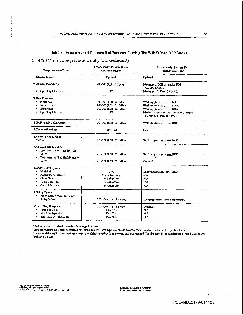
RECOMMENDeD PRACTICES FOR BLOWOUT PnEvErrnoN OUIPMENT SYSTEMS FOFI DRILLING WELLS
Table 3RecommGrtded Pressure Test Practices Floating Rigs With Subsea BOP Stacks
Initial Test dive rier system prior to spud er al prior to running stack
Recommended Pressure Test Recommended Pressure Test
Component to be isted Low Pressure psi High Pessure psi
Diverter Element Options Optional
Annular Preventers 200-3001.38 -2.1 MPa Minimum of 70% of annular BOP
working pressure
Operating Chambers N/A Minimum of 150010.3 MPa
Ram Preventers
Fixed Pipe 200-3001.38 -2.1 MPa Working pressure of ram SOPsVariable Bore 200.300138 2.1 MPa Working pressure of ram BOPsBlind/shear 200-300138 2.1 MPa Working pressure of ram SOPs
OperAting Chambers N/A Maximum operating pressnrc recommended
by ram SOP manufacturer
BOP-to-WHD Connector 200-3001.38 2.1 MPa Working pressureof ram BOPs
IDiverter Flowlins Flow Test N/A
Choke Kilt Linen
Vdves 200-3001.38 2.1 MIS Working pressure of ram 1301s
Choke Kill Manifold
Upsiream of Lest1-11gb Pressure
Valve 200-3001.38 2.1 MPa Working pressure oframllOPa
Downstream of Last 1-11gb Pressure
Valve 200.3001.38 2.1 MPa Optional
SOP Control System
Manifold N/A Minimum of 3000 20.7 MPaAccumulator Pressure
Verify Precharge N/A
Close Time Function Taut N/A
Pump Capability Function Test N/A
Control Stations FunctIon Test N/A
Safety Valves
Kelly Kelly Valves and Floor
Safety Valves 200-300 1.38 -2.1 Mis Working pressureof the component
10 Aaxiliary Equipment 200-3001 38 -2.1 Mis Optional
Riser Slip Joint Flow Test N/A
Mud/Gas Separator Flow Test N/A
Trip Tank Plo-Show etc Flow Test N/A
The lowpressulO test should be stable for at least minutes
bThv high pressure test should be stable or at least minutes flow-type tests should lie of sufficient duration to observe for significant leaks
The rig available well control equipment may have higher rated working pressure than site required Th site-specific test requirement should be considered
for these siluations
CGpylhI American PeIroleo hmutrta
PruVId.d by Il-IS sndor llecriso seilfa API Sold toaST CONSULTING VV5555362
No roprodaaotioi or roiworsaiS permuted WilhorrI Ilsenon from INS N0L for Rouufe2510i 5118 l644 GMT
PSC-MDL21 79-011102
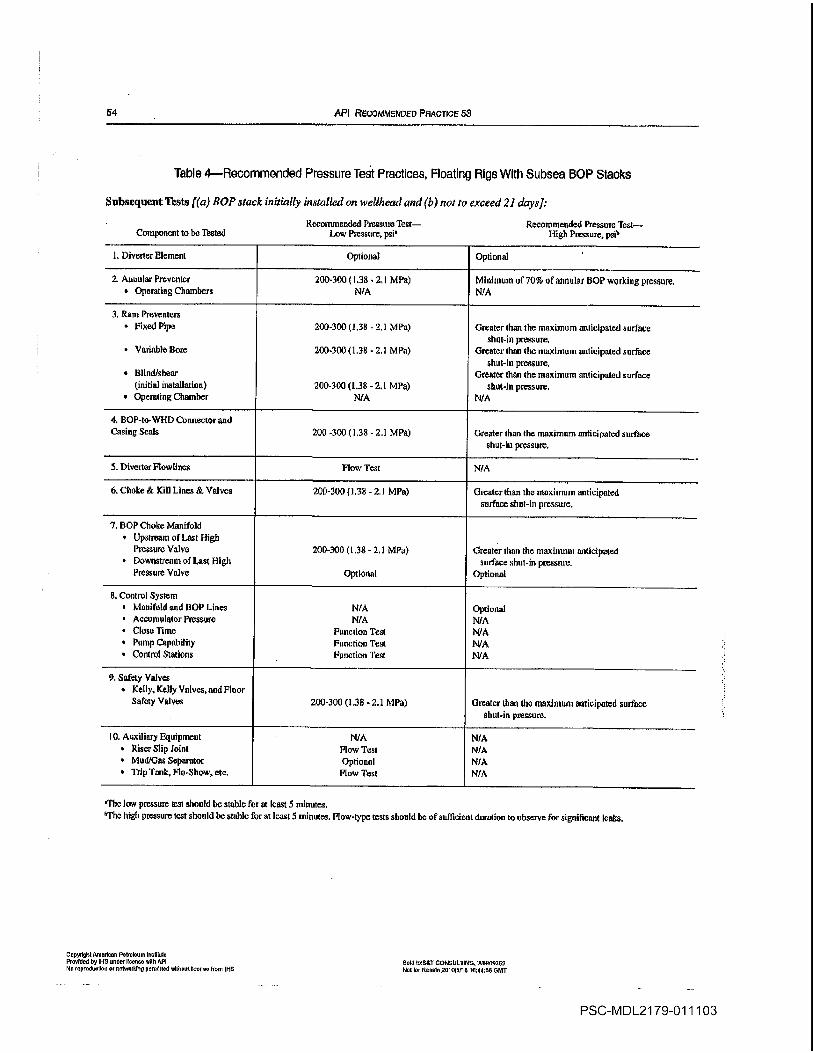
54 API RECOMMENDED PRACnoE 53
Table 4Recommended Pressure Test Practices Floating Rigs With Subsea BOP Stacks
Subsequent Tests BOP stack initially installed on well/send and is not to exceed 21 daysj
Recommended Pressure Teas Recommended Pressure TestComponent to be Thsled Low Pressure psi High Pressure psi5
Diverler ElementOptional Optional
Asusular Preventer 200-30013S MPe Miuitnum of 70% of annuls BOP workieg pressure
Operating Chambers N/A N/A
Rant Presenters
Fixed Pipe 200-3001.38 -2.1 MPa Greater than the maximum anticipated surface
shut-inpressure
Variable Sore 200-3001.38 2.1 MPa Greater than the maximum anticipated surfuce
shut-in pressure
Blind/shearGreater than the maximum anticipated surface
initial installation 200-300 1.38 -2.1 MPa slaut-In pressure
Operating Chamber N/A N/A
BOP-to-WHD Connector and
Casing Seals 200 -300 1.38 2.1 Mls Greater than the maximum anticipated surface
that-in pressure
Diverler Flowlines flow Test N/A
Choke Kill Lines Valves 200-3001.38-2.1 MPe Greeter than the maximum anticipated
surface shut-In pressure
SOP Choke Manifold
Upstream of Last High
Pressure Valve 200-300 1.38 2.1 MPa Greater than the maxiussmanticipated
Downstream of Last 111gb surface shut-in pressure
Pressure ValveOptional Optional
Control System
Manifold and SOP Lines N/AOptional
Accussusintor Pressure N/A N/AClose Time Function Teat N/A
Pump Capability Funcsioa Teat N/AControl Stations Function Test N/A
Safety Valves
Kelly Kelly Valves and Finor
Safety Valves 200-300 1.38 LI MPa Greater than she maximum aeticiputed surface
shut-in pressure
10 Auxiliary Equipment N/A N/A
Riser Slip Joint Flow Test N/A
Mud/GasSeparator Optional N/A
Trip Tank Flu-Show etc Flow Test N/A
Thc low pressure teas should be stable foe as least minutes
bThe higls pressure tear should be stable for at least minutes Flow-typo teats should be of sufficient duration to observe for significant leaks
copysguamorloes PoSoloom Iboabdo
Provtdod by Il-ta osder Plots vdttt yoI sold losT CONsutlIldu W5509562so roprodsollori or oolworldrru pormisod s5lioottcorso frooi Il-Is Not br ResaboZslslsfls le44ss SMT
PSC-MDL21 79-011103
RECOMMENDED PRACTICES FOR BLOWOUT PREVENTION EOUIPMENT SYSTEMS FOR DRILLING WELLS 55
The rigs available well control equipsnent may have higher rifled work
ing pressure tims required Site specific test requirements should be consid
ered In these situations
18.5 SUBSEA SOP STACK EQUIPMENT
18.5.1 The subsea stack equipment includes the subsea
wellbore pressure containing equipment above thc wellhead
and below the ball/flex joint This equipment includes the
weilbead and LMRP connectors ram BOPs spools annu
lars choke and kill valves and choke and kill lines
18.5.2 Unless restricted by height the entire stack should
be pressure tested as unit
18.5.3 Annular SOPs should be tested using the smallest
OD pipe to be used
18.5.4 Fixed bore pipe rams should be tested only on the
pipe 00 size that matches the installed pipe ram blocks
18.5.5 Variable bore rams should beinitially pressure
tested on the largest and the smallest OD pipe sizes that maybe used during the well operation
18.5.6 Blind rams and blind shear rams should not be tested
when pipe is in the stack The capability of the shear ram and
tam operator should be verified with the manufacturcr for the
planned drill string The shear ram preventer design and/or
metallurgical differences among drill pipe manufacturers may
require high closing pressures for shear operations
18.5.7 When drill pipe hangoff is possibility during well
control hangoff procedures should be preplanned The manufacttiters recommended hangoff load capacity for fixed-bore
ram blocks should be considered Example hangoff proce
dures are included in API Recommended Prnctice 59 The
origihal ram l3OP equipment manufacturer should be con
sultdLl regarding hanging oIl drill pipe on variable bore ram
BOils
18.5.8 Prior to surface testing each ram BOP the second
ary rod seal emergency packoff assembly should be
checked to ensure the seals have not been energized Should
the ram shaft seal leak during the stump test the seal shall he
repaired rather than energizing the secondary packing
18.5.9 Ram flOPs equipped with hydraulic ram lucks
should be pressure tested with ram locks in the closed posi
tion and closing pressure vented
16.5.10 The BOP elastomeric components thnt may be
exposed to well fluids should be verified by the BOP manufacturer as appropriate for the drilling fluids to he used and
for the anticipated temperatures Consideration should be
given to the temperature and fluid conditions during well test
ing and completion operations
18.5.1 0.1 Manufacturers markings for BOP elastcmeric
components should include the duromcter hardness generic
Copyrlshl AmIoan Pelrofeum IntIIuIo
Proof dd by IllS ondrIIcooemlth API
No reproductIon or rotworldryprrrlttod without Itcoro from IHS
type of compound date of manufacture part number and
operating temperature range of the component
18.5.10.2 Consider replacing critical 80 elastomeric
components on well control equipment that has been out of
service for months or longer
18.5.11 Flexible choke and kill lines should be tested to
the same pressure frequency and duration as the ram BOPs
18.5.12 properly precharged surge bottle should be
installed adjacent to the annular HOP if contingency well
control procedures include stripping operations
18.5.13 The drill pipe test joint and casing ram test sub
should he constructed of pipe that can withstand the tensile
collapse and internal pressures that will be placed on them
during testing operations
18.6 CHOKES AND CHOKE MANIFOLDS
18.6.1 The choke manifold upstream of and including the
last high pressure valves refer to Figure should be tested
to the same pressure as the ram BOPs
18.6.2 The configuration of pipes and valves downstream
of the last high pressure valve varies from installation to
installation Each configuration should be verified for
mechanical integrity
18.6.3 The valves and adjustable chokes should be oper
ated to verify smooth operation
18.6.4 Adjustable chokes are not required to be full sealing
devices Pressure testing against closed choke is not
required
18.7 ACCUMULATOR SYSTEM
182.1 ACCUMULATOR CLOSING TEST
The purpose of this test is to verify that the accumulator
system is properly sized to support the fluid volume and pres
sure requirements of the BOPs on the rig This test should be
performed prior to running the SOPs subsea and the initial
landing of the stack and prior to each subsequent pressure test
using the following procedures refer to sample worksheets
and examples in Appendix
Position properly sized joint of drill pipe or test mandrel in the BOPs
TUrn off the power supply to all accumulator charging
pumps air electric etc.
Record the initial accumulator pressure The initial accu
mulator pressure should be the designed operating pressure of
the accumulator Manifold and annular regulators should be
set at the manufacturers recommended operating pressure for
Lhe BOP stack
arid Iom1 CONSULTING W0959302
Not for RoIo201015I5 164445 GMT
PSC-MDL21 79-011104

56 API REcoMMEoEo PRACTICE 53
Individually close and openeach ram BOP excepting
blind/shear ram BOPs recording the closing time and fluid
volume required for each function To simulate the function
ing of the blind/shear rams close and open one set of pipe
rams again Closing times shall meet response times estab
lished in 13.3.5
Function the hydraulic operated valves and record the time
and volume required
Close and open one annular flOP and record the time and
volume
Record the final accumulator pressure The final accumu
latorpressure shall be equal to or greater than 200 psi 1.38
MPa above precharge pressure
18.8 AUXILIARY EQUIPMENT
Auxiliary equipment includes the upper and lower kelly
valves drill pipe safety valves inside flOPs and kelly
18.8.1 Prior to spud or initial use determine from the man
ufacturers documentation whether kelly valves and safety
valves can be opened when rated working pressure below the
valve is equalized by applying pressure from the top
18.8.2 Verify that appropriate operating tools wrenches
etc are readily available for kelly cocks and safety valves
18.9 MUD/GAS SEPARATOR
Prior to spud pump water or drilling fluid into the separa
tor inlet and verify unobstructed flow from the separator or
connections If the separator is equipped with float to regu
late liquid discharge observe that the float properly regulates
liquid discharge
18.10 INSPECTIONS
18.1 0.1 BETWEEN WELLS
After each well the well control equipment should be
cleaned visually inspected preventative maintenance per
formed and pressure tested before installation on the next
well The manufacturers test procedures as prescribed in
their installation operation and maintenance IOM manual
should be followed along with the test recommendations of
Table All leaks and malfunctions should be corrected prior
to placing the equipment in service
DopydghtAmo.lcon Pekoleum Insnfuro
ProvIded byIH6 undrIIono oAth API
Mo repredunllno or net.nnr6Io pormltfod relitonoit facets freon tIP
18.10.2 VISUAL INSPECTIONFLEXIBLE CHOKEAND KILL LINES
visual external inspection of flexible choke and kill lines
through the entire length of the line should include
Outer Jacket Visually inspect to ensure that the outer
jacket is intact to protect polymeric sheath underneath from
tearing and being punctured
Verify that the outer jacket is properly attached at both
end fittings
Vetify that the entire surface of the polymeric sheath is
protected
If any damage is noticed on the outer jacket verify that
damages would not be detrimental to the polymeric
sheath
Termination Record any damage to the coating on the
end-fitting and monitor progression of damage Facilitate
repair if necessary
Connector Particularly inspect the seal area of the con
nectors recording any damage and monitor progression of
damage
18.10.3 MAJOR INSPECTIONS
After every 3-5 years of service the BOP stack choke mani
fold and diverter components should be disassembled and
inspected in accordance with the manufacturers guidelines
Elastonieric components should be changed out and sur
face finishes should be examined for wear and corrosion
Critical dimensions should be checked against the manufac
turers allowable wear limits Individual components can be
inspected on staggered schedule
full internal and external inspection of the flexible choke
and kill lines should be performed in accordance with the
equipment manufacturers guidelines
18.11 MAINTENANCE
18.11.1 INSTALLATION OPERATION ANDMAINTENANCE MANUALS
Manufacturers installation operation and maintenance
TOM manuals should be available on the rig for all the BOP
equipment installed on the rig
18.11.2 CONNECTIONS
Studs and nuts should be checked for proper size and
grade Using the appropriate lubricant torque should be
applied in criss-cross manner to the flange studs All bolts
should then be rechecked for proper torque as prescribed in
API Specification 6A When making up connections exces
sive force should not be required to bring the connections into
alignment
nold Io8T CONPIJITII4G W0669362
Itni for ResoIe261615t16 164466 DM7
PSC-MDL21 79-011105
RECOMMENDED PRACTICES FOR BLOWOUT PREVENTION EQUIPMENT SYSTEMS FOR DRILLINO WELLS 57
Ring gaskets coated with resilient material such as rubber
or polytetrafluoroethylene FIFE should not be used Due to
the limited amount of deformation which groove can make
in nag as it is compressed during installation it is not rec
ommended to reuse ring gaskets
When making up proprietary hubbed connections the
manufacturers recommended procedure should be followed
Subsea BOP stacks should have each newly made up con
nection retorqucd afler it has been in service for one well to
reduce the effects of bolt embedment relaxation that may
have occurred
18.11.3 REPLACEMENT PARTS
Spare parts should be designed for their intended use by
industry approved and accepted practices After spare part
installation the affected pressure-containing equipment shall
be pressure tested Elastomeric components shall be stored in
manner recommended by the equipment manufacturer
The original equipment manufacturer should be consulted
regarding replacement parts If replacement parts are
acquired from nonoriginal equipment manufacturer the
parts shall be equivalent to or superior to the original equip
ment and be fully tested design verified and supported by
traceable documentation
18.41.4 TORQUE REQUIREMENTS
Manuals or bulletins containing torque specifications
should be available on the rig As previously stated in 18.11.2
torque specifications and the lubricants coefficient of friction
should be considered when torquing fasteners Deviating
from the specified lubricant will alter the required torque
18.11.5 EQUIPMENT STORAGE
When BOP is taken out of service for an extended period
of time it should be completely washed steam cleaned and
machined surfaces coated with corrosion inhibitor The
rams or sealing element should be removed and the internals
washed inspected and coated with corrosion inhibitor
Connections should be covered with corrosion inhibitor and
protected with wooden or plastic covers The hydraulic oper
ating chambers should be flushed with corrosion inhibitor
and hydraulic connections plugged For cold climates pre
cautions should be taken to prevent damage The equipment
should be elevated to prevent it from standing in water The
original equipment manufacturer should be consulted for any
further specific details
18.11.6 LUBRICANTS AND HYDRAULIC FLUIDS
The original equipment manufacturer should be consulted
for the proper lubricants and control fluids to be used On sur
face applications tight mineral-based hydraulic fluid can
be used In offshore operations mixture of potable water
Copyrlghi AmorIon Pofrorºom InstItute
Pooldod by fl-IS uodoIlooto MIh API
Nompoduollon or tetwoAlog potent Uodwfttnoot f.. from fl-IS
and water soluble oil specifically formulated for this pur
pose is frequently used Diesel fuel kerosene drilling fluid
and salt water shall not be used in BOP hydraulic control
system
18.11.7 WELD REPAIRS
Weld repairs on pressure containing and load bearing com
ponents shall only be performed in accordance with API
Specification lilA API Specification 6/t manufacturers
standards or other applicable standards
All welding of wellbore pressure containing components
shall comply with the welding requirements of NACE Stan
dard MRO175 Verification of compliance shall be established
through the implementation of the repairers written weld
procedure specification WPS and the supporting procedure
qualification PQR Welding shall be performed in accor
dance with WIS written and qualified in accordance with
Article II of ASME Boiler and Pressure Vessel Code Section
IX The original equipment manufacturer should be consulted
to verify proposed weld procedures
Field welding shall not be performed on flexible lines or
end connections without prior consultation with the original
equipment manufacturer
18.11.8 MUD/GAS SEPARATOR INSPECTION ANDMAINTENANCE
The rig maintenance and inspection schedule should pro
vide for periodic nondestructive examination of the mud/gas
separator to verify pressure integrity This cxumination maybe performed by hydrostatic ultrasonic or other examination
methods
18.12 QUALITY MANAGEMENT
18.1 2.1 PLANNED MAINTENANCE PROGRAM
planned maintenance system with equipment identified
tasks specified and the time intervals between tasks stated
should be employed on each rig Records of maintenance per
formed and repairs made should be retained on file at the rig
site or readily available
18.12.2 MANUFACTURERS PRODUCT ALERTSEQUIPMENT BULLETINS
Copies of equipment manufacturers product alerts or
equipment bulletins should be maintained at the rig site or
readily available for the applicable BOP equipment
SoIdtoST CONSULTING 000009362
Not for 0000to2tIotttft 164400 GMT
PSC-MDL21 79-011106

58 API RECOMMENDED PRACTICE 53
18.13 RECORDS AND DOCUMENTATION
18.1 3.1 DRAWINGS
Drawings showing ran space Cut and bore of the BOP
stack and drawing of the choke manifold showing the pres
sure rating of the components should be on the rig and main
tained up to date Refer to Figure 20 for an example
drawing.A bill of material should accompany the equipment
drawings to correctly identify the equipment and allow the
procurement of correct replacement parts
Changes to the SOP Control system should be docu
mented method should he established to control the draw
ings ensuring that up-to-date documentation is maintained
18.13.2 EQUIPMENT DATA BOOK ANDCERTIFICATION
Equipment records such as API manufacturing documenta
tion MACE certification and factory acceptance testing
reports should be retained Where required dopies of the
manufacturers equipment data book and third party certifica
tion should be retained for review
18.1 3.3 MAINTENANCE HISTORY AND PROBLEMREPORTING
maintenance and repair historicaL file should be retained
on each major piece of equipment This file should follow the
equipment when it is transferred Equipment malfunctions or
failures should be reported in writing to the equipment maiiu
facturer as stated in API Specification 6A
18.13.4 TEST PROCEDURES AND TEST REPORTS
Shop testing after major inspection or equipment weld
repairs should be performed according to the manufacturers
written procedures
18135 API DOCUMENTS
Copies of appropriate API documcnts should be available
at the rig site or readily available For well control equipment
these should include the following
API Specification 6A Well/wad and Christmas Tree
Equipment Order No GO6AAPI SpecifIcation 6A Drill Through Equipment Order
No 007240API Specification lóC Choke and Kill Systems Order
No 007242API Specification 16D Control Systems for Drilling Well
Control Equipment Order No 007243
API Recommended Practice 53 Blowout Prevention
Equipment Systems for Drilling Wells Order No 053003
API Recommended Practice 16Q Design Selection
Operation and Maintenance of Marine Drilling Riser Sys
tems Order No 007249API Recommended Practice 64 Diverter Systems Equip
ment and Operations Order No 009302
These Al documents are available from
American Petroleum Institute
Publications and Distribution
1220L Street NWWashington DC 20005
Telephone 202/682-8375
19 SOP Sealing Components
19.1 FLANGES AND HUBS
API specifications for flanges and hubs including sizes
service conditions dimensions and other design require
ments for blowout preventers are contained in the latest edi
tion of API Specification 6A and API Specification l6A
When flange connections are used API flanges should be
installed for SOP use Hubs may be API or equivalent design
in industry drilling service Manufacturers should be con
sulted for service conditions dimensions and other specifica
tions hub and clamp connection consists of two hubs
pulled together against metal seal ring by two or three
piece clamp This type connection requires fewer bolts to
make up and is lighter than the equivalent flanged connection
19.2 EQUIPMENT MARKING
Marking of wellhead and Christmas tree equipment and
drill through equipment should be perAPI Specification 6A
and API Specification 16A respectively
19.3 RING-JOINT GASKETS
Type RX and BX ring-joint gaskets should be used for
flanged and hub type blowout preventer connections iii that
they are self-energized type gaskets API ISpe ring gaskets
are not self-energized type gasket and are not recommended
for use on well control equipment lix gaskets are used with
API l3rpe fiB flanges and 16B hubs and BX gaskets are used
with ltpe 6BX flanges and I6BX hubs Detailed specifica
tions for ring-joint gaskets are included in API Specification
6A and in API Specification bA Gasket materials coatings
and platings should be in accordance with API Specification
6A Identification markings should be in accordance with API
Specification fiA and API Specification fiA
19.4 BOLTING
Range and clamp stud bolt and nut specification require
ments should be in accordance with API Specification 6A and
CopyrIhl Andooo Polovrnlroliluto
ProvIded by H-IS and Iss will API
No ioproductIrr ornetgcrklrrg pormIlted allIroul Iloenoe horn 115
Sold toOT CONSULlltdG W0900362
NoSier RooIo2OlOl5flN 64456 0141
PSC-MDL21 79-011107
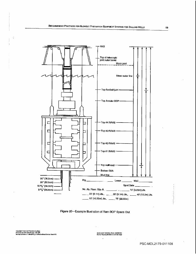
RECOMMENDED PRACTICES FOR BLOWOUT PREVENTION EQUIPMENT SYSTEMS FOR DR1LLrNO WELLS
Figure 20Example Illustration of Ham BOP Spaco Out
59
Copynt9ht merIcnn Pelroleum lnnliiole
Provided by il-IS under license oilhPI
No roprodocton or nelwerbin permitted without license Irene Il-IS
Sold toSST CONSULTING WQIOOSQZ
blot for Roonle2OlSJSlld 184466 GluT
Moon po
Lease ________ Well __________
Spud Date ___________
No Jts Ricer Slip JI _________ _________ 10 3.05m Jts
20 6.lni Jts 30 9.lm Jls 40 12.2m Jts
50 15.25ni Jts _75 22.88m
PSC-MDL21 79-011108
60 API RECOMMENDED PRAcTICE 53
API Specification 16A Identification marking of bolting
components should be in accordance with API Specification
6A and API Specification 16k
19.5 ELASTOMERIC COMPONENTS
Each resilient nonweilbore nonmetallic Component
such as elastomeric seals used in BOP actuating systems
should be marked or tagged using codification system
developed by the equipment manufacturer The markings
should include information regarding the durorneter hard
ness generic type of compound refer to Table date of
manufacture month/year lot/serial number manufac
turers part number and the operating temperature range of
the component Spare POP seals and packing units should
be stored in accordance with the original equipment manufacturers recommendations
Note It Is important to note that some blends or drilling and completion flu-
iris have detrimental effects on clastomer compounds Theoriginal equip
ment mjhtufncturer should be consultedsegarding compatibility with drilling
and coripletion fluids
196 ELASTOMERIC COMPONENTS FOR
HYDROGEN SULFIDE SERVICE
shortens as temperature increases from 150F to 200F
65.6C to 93C In the event flow line temperatures in
excess of 200F 93C are anticipated the equipment manufacturer should be consulted Elastomeric components should
be changed out as soon as possible after exposure to hydro
gen sulfide under pressure
Changes prescribed by the primary equipment manufac
turer to render equipment acceptable for service in hydro
gen sulfide environment should not be overlooked in
providing for replacement and repair parts
197 INTEGRAL CHOKE AND KILL LINES
Typical marine riser joints have integral choke and kill
lines This provides redundancy and allows for well control
operations as follows
Circulating down one line and up the other line
Circulating down the drill pipe and up either line
Generally choke/kill lines and auxiliary lines of one
marine riser joint are connected to their counterparts on
adjoining riser joints by box-and-pin stab-in couplings The
box contains an elastomeric radial seal that expands against
the smooth abrasion-resistant sealing surface of the pin when
the line is pressurized These stab-in couplings also facilitate
fast makeup while deploying the marine riser
Kel-F
Ilypaton
F-PR
F-PT
Vilon
Natural
Isoprene
Natural or synthetic
Nitrite
Acrylic
Diene
Nceptvne
Vistaaex
Thiolcol
Silicone
SBROR-SUrethane
Chemical Maine
tuobutyieno-tsoprene
Epichtorohydtin
Epichlorohydtin-Ethyleree O4de
Chioto Fluoro Etastoiaer
Cllomsolfonated Polyethylene
Ethylene-propylene Copolymer
Ethylene-propylene Teipolymer
Fluorocarbon
Potyisoprene
Pulyisopiene
Butndicnc-ncrytunitrile
Pclyacrylic
Polybutadieno
Polychioroptene
Polyisobutylene
Polyseltlde
Polysiioxanea
Stytene-bittadiene
Dilroeyanates
copoduot Aororlon Pesolom InllIulo
Provided by Il-IS urrdor Ileorso with API
Noroprodooton orrrotworklnu poorriltod sdthoul Ilcenoo thorn IHS
ASTM
1418
Code
hR
CO
F-Co
CFMCSM
F-PM
EPDM
P1CM
Nit
AR
NBR
ACMBR
CR
IM
SI
SBR
Sold boOST coNsuLilNo W0505302
Not tot Rol2O1Ob5l1S t4456 OMT
Many elastomeric components arc subject to hydrogen sul
fide attack Nitrile elastometic components that meet other
job requirements may be suitable for hydrogen sulfide service
provided drilling fluids are properly treated Service life
Table 5Elaston-ier Compound Marking Code
Refer to API SpecIfication 6A
Common Name
Butyl
19.8 SUBSEAWELLHEAD CONNECTOR
The primary seal for subsea wellhead connectors is pres
sure-energized metal-to-metal type seal Initial sealing
requires that the metal seal be preloaded sufficiently to main
tain contact with the mating seal surface and effect low pres
sure sealing capability These seals are not recommended for
re-use Some wellhead connectors are equipped with resilient
secondary seals which may be energized should the primary
seal leak This type seal should be utilized under emergency
conditions only
199 MARINE RISER
The primary seal for the marine riser couplings may be
elastomeric or metal-to-metal Care should he taken to care
fully clean and inspect all seals prior to running the marine
riser
The primary telescopic joint seal assembly consists of
hydraulic or pneumatic pressure-energized resilient packing
elements
19.10 SUBSEA CONTROL SYSTEM
Primary hydraulic system seal between the male and
female sections of the control pods is accomplished with
resilient seals of the 0-ring pressure-energized or face-
sealing types
PSC-MDL21 79-011109
REcoMMENDED PRACTICES Fon Blowout PREVENTION EQUIPMENT SYSTEMS FOR DRILLING WELLS 61
The hydraulic junction boxes consist of stab subs or multi-
pie check valve type quick disconnect couplings The primary
seals are 0-rings These 0-ring seals should be inspected
each time the junction box is disconnected
The primary pod valve seals vary according to the manufacturer with both resilient and lapped metal-to-metal type
seals used
20 Blowout Preventers for HydrogenSulfide ServIce
20.1 APPLICABILITY
Where there is reasonable expectation of encountering
hydrogen sulfide gas zones that could potentially result in the
partial pressure of the hydrogen sulfide exceeding 005 psia
0.00034 MPa in the gas phase at the maximum anticipated
pressureSOP equipment modifications should be made
Recommended safety guidelines for conducting drilling oper
ations in such an environment can be found in API Recom
nndecl Practice 49
202 EQUIPMENT MODIFICATIONS
202.1 Equipment modifications should be considered
sthce many metallic materials in hydrogen sulfide environ
mbnt sour service are subject to form of hydrogen embrit
ttement known as sulfide stress cracking SSC This type of
spontaneous brittle failure is dependent on the metallurgical
properties of the material the total stress or load cither inter
nal or applied and the corrosive environment list of
acceptable materials Is given in MACE Standard MRO175
20.2.2 list of specific items to be changed on annular nnd
rain type flOPs and valves for service in hydrogen sulfide
environment should be furnished by the manufacturer As
guide all metallic materials which could be exposed to
hydrogen sulfide under probable operating conditions should
be highly resistant to sulfide stress cracking
20.2.3 The maximum acceptable hardness for all preventer
and valve bodies and spools shall be in accordance with
MACE Standard MRO175
20.2.4 Ring-joint gaskets should meet the requirements of
API Specification I6A and he of the material and hardness
specified in API Specification 6A
20.2.5 All bolts and nuts used in connection with flanges
clamps and hubs should be selected in accordance with provisions otAPt Specification 6k
20.2.6 All lines crosses valves and fittings in the choke
manifold system and the drill string safety valve should be
constructed from materials meeting applicable requirements
of API Specification 5L and API Specification 6A Heat treat
ing and other applicable requirements as stipulated in NACE
CoyyrigldArnrien Petroleum evade
Provided by IllS under iluee with PINo repredrzeNer networking pormllled yrilIwet Iloerree hem INS
Standard MR0175 should also be reviewed and considered
Field welding upstream of the chokes should be kept to
minimum and if performed should meet original shop con
struction standards and procedures
20.2.7 Elastomeric components are also subject to hydro
gen sulfide attack Mitrile elastomeric components which
meet other requirements may be suitable for hydrogen sulfide
service provided drilling fluids are properly treated Service
life shortens rapidly as temperature increases from 150F to
200P 65.6C to 93C In the event fiowline temperatures in
excess of 200F 93C are anticipated the equipment manufacturer should be consulted Elastomeric components should
be changed out as soon as possible after exposure to hydro
gen sulfide under pressure
20.2.8 Changes prescribed by the primary equipment manufacturer to render equipment acceptable for service in
hydrogen sulfide environment should not be overlooked in
providing for replacement and repair parts
21 Pipe Stripping ArrangementsSurface BOP Installations
21.1 PURPOSE
During operations on drilling or producing well
sequence of events may require tubing casing or drill pipe to
be run or pulled while annulus pressure is contained by the
SOPs Such practice is called stripping Stripping is normally
considered an emergency procedure to maintain well control
however plans for certain drilling completion or well work
operations may include stripping to eliminate the necessity of
loading the well with fluid
21.2 EQUIPMENT
21.2.1 Stripping techniques vary and the equipment
required depends upon the technique employed Each strip
ping operation tends to be unique requiring adaptation to
the particular circumstances Therefore the equipment and
the basic guidelines discussed herein are necessarily general
in nature Stripping requires surface equipment which
simultaneously
Pennits pipe to be pulled from or run into well
Provides means of containing and monitoring annular
pressure
Permits measured volumes of fluid to be bled from or
pumped into the well
21.2.2 To facilitate immediate stripping operations the fol
lowing should he considered
Precise measurements of the SOP spacing should be
posted on the drillers control panel
Choke and kill line access locations on the SOP stack
weld leSy coNsuLylNo W0509382
Net fey Nnoi201015/lP lNrd456 aMy
PSC-MDL21 79-011110

62 API RECOMMENDED PRACTICE 53
The annular regulator for the annular BOP pressure should
be responsive to less than 100 psi 0.69 MPa differential
pressure If an accumulator bottle is utilized the bottle should
be installed as Close to the annular BOP as possible in the
Closing line and an additional bottle may be installed in the
opening line The prechargo pressure of these accumulators
should be determined and set for the specific rig and well
conditions upon nippling up the 801s
Connections should be made from the choke manifold to
thetrip tank for accurate fluid volume measurements as
backup to other volume measuring systems
21.3 PERSONNEL PREPAREDNESS
The well site supervisor and orew shall have thorough
working knowledge of all applicable well control principles
and equipment employed for stripping Equipment should be
rigorously inspected and if practicable operated prior to use
21.4 SURFACE EQUIPMENT
21.4.1 For stripping operations the primary surface equip
ment consists of BOPs cloiag units chokes pumps gauges
and trip tanks or other accurate drilling fluid measuring
equipment
21.4.2 The number type and pressure rating of the BOPs
required for stripping are based on anticipated or known sur
face pressure Often the blowout preventer stack installed for
normal drilling is suitable for low pressure stripping if spaced
so that tool joints or couplings can be progressively lowered
or pulled through the stack with at least one sealing element
closed to contain well pressure
21.4.3 Annular BOPs are most commonly employed for
stripping because tool joints and some couplings can be
moved through the BOP without opening or closing of the
packing element High wellbore pressures may hinder the
ability to allow passage of tool joint through the closed
annular DO packing element limiting use of these presto-
tees in some stripping operations To minimize wear the clos
ing pressure should be reduced as much as possible and the
element allowed to expand arid contract breathe as tool
joints pass through spare packing element should be avail
able at the well site during any stripping operntion
214.4 Ram type BOPs or combinations of ram and annu
lar SOPs are employed when pressure and/or configuration of
the coupling or tool joint could cause excessive wear if the
annular DO were used alone Ram BOPs must be opened to
permit passageof tool joints or couplings When stripping
between 801s provision should be made for pumping into
and releasing fluid from the space between BOPs Pressure
across the sealing element should be equalized prior to open
ing the BOP to reduce wear and to facilitate operations of the
DO After equalizing the pressure and opening the lower
Copyright Mrerioen Petroleum irrsgeto
Provided by li-IS under license orith APi
No reprcdoriion or networking ponnitiod without license hem INS
DO volume of drilling fluid equal to that displaced as the
pipe is run into or pulled from the well should be respec
tively bled from or pumped into the space between the flops
To minimize wear the closing pressure placed on ram BOPs
during stripping operations should be reduced as much as
possible and still maintain seal
21.4.5 Chokes are required to control the release of fluid
while maintaining the desired annular pressure Adjustable
chokes which permit fast precise control should be
employed Parallel chokes which permit isolation and repair
of one choke while the other is active are desirable on
lengthy shipping operations One of the parallel chokes
should be remotely operated Because of the severe service
spare parts or spare chokes should be on location Figure 21
ilustrates one example BOP stack/choke and kilt manifold
installation suitable for stripping operations
21.4.6 pump truck or skid mounted pump is normally
employed when stripping out and may be required white
stripping in The relatively small volume ofdrilling
fluid
required to replace the capacity and displacement of each
stand or joint of pipe may be accurately measured and
pumped at controlled rate with such equipment Well fluid
from below the DO should not be used to equalize pressure
across the stripping BOP
21.4.7trip
tank or other method of accurately measuring
the drilling fluid bled off leaked from or pumped into the
well within an accuracy of one-half barrel is recommended
21.4.8 The lowermost ran shall not be employed in the
stripping operation This ram should be reserved as means
of shutting in the well if other components of the SOP stack
fail This DO should not be subjected to the wear and stress
of the stripping process
21.4.9 DO control systems with associated piping and
regulators are criticnl for stripping operations
21.4.10 Gauges to accurately measure the annulus pressure
should be used Low range pressure gauges may be needed
and should be available
21.5 SUBSURFACE EQUIPMENT
21.5.1 Equipment which is run or set inside the pipe being
stripped includes safety valves inside blowout preventers
floats and various plugs The lower kelly valve while not
strictly subsurface tool may be run into the well
21.5.2 Drill pipe safety valves employed for stripping are
essentially full-opening valves usually of the ball type with
outside dimensions which permit the valve to be run through
the flOPs and into the well If well is coming in through the
drill pipe safety valve in the open position can be stabbed
into the drill pipe then closed Additional equipment such as
SutdtoOET COidStuLliidG WOySu62
Not in Ennein.SSiOitiuiO te44nC CMI
PSC-MDL21 79-011111

-i ill
-o 01 CI
DO
Cr
05
Ra
ted
work
ing
pre
ssure
Check
Fro
m
fluid
pum
p
No
min
al
8cm
To
pit
andlo
r
Re
mo
tely
opera
ted
mud/g
as
or
adju
sta
ble
ch
oke
se
pa
ra
toii
optional
overb
oard
OS
cm
IBle
ed
lin
eto
Rem
ote
kill
line
Rem
ote
pum
pconnection
optional
508cm
-D N-i
Rem
ote
lyopera
ted-
or
adju
sta
ble
choke
__
__
_R
ate
dw
ork
ing
pre
ssure
Fig
ure
21E
xam
ple
Surlace
BO
PS
tack/C
hoke
Manifold
Insta
llato
n
64 API RECOMMENDED PRACTIcE 53
inside blowout preventers float valves or seating nipples can
then be installed the safety valve opened and run into well
21.5.3 Inside blowout preventers can be stabbed if well
is coining in through the drill pipe or installed above drill
pipe safety valve It should be remembered that inside blow
out preventer tools may not be full-opening so that other
tools Cannot be run below them without difficult milling
operation
21.5.4 Float valves can be used for stripping operations by
installation above drill pipe safety valve or they can be run
as routine items in the drill string These tools are essentially
check valves either flapper or poppet which seal pressure
from below but permit fluid to be pumped down the drill pipe
The flapper type valves are easier to mill out and tools or pipe
can be lowered through them
21.5.5 Several types of plugs are available to effect an
internal seal of the pipe being stripped Drill pipe or tubing
may be equipped with seating nipples that permit plugs to
either be pumped down or run on wireline and landed in
profile nipple preventing flow up through the drill pipe or
tubing Some of these plugs serve as check valves halting
flow from below but pennitting passage of fluid from above
Designed to be retrievable by wireline these plugs may be
removed to permit access below the seating nipple Other
nonretrievable plugs can be set in drill pipe or casing by elec
tric or shooting line Such plugs are run through pressure
lubricators and set by explosive charge
22 Pipe Stripping ArrangementsSubsea BOP Installations
22.1 PURPOSE
During operations on drilling or producing well
sequence of events may require tubing easing or drill pipe to
be run or pulled while annulus pressure is contained by
BOPs Such practice is called stripping Stripping is normally
considered an emergency procedure to maintain well control
however plans for certain drilling completion or well work
operations may include stripping to eliminate the necessity of
loading the well with fluid
22.2 EQUIPMENT
22.2.1 Stripping techniques vary and the equipment
required depends upon the technique employed Each strip
ping operation tends to be unique requiring adaptation to
the particular circumstances Therefore the equipment and
the basic guidelines discussed herein are necessarily general
Copyllt Amerloon Pobotoco lntibao
Provided by Il-IS under license wilt SNNo rotr.odoosno ornotworldog prnrlltod without Iloonso Iror Il-IS
in nature Stripping requires surface equipment which
simultaneously
Pennits pipe to be pulled from or run into well
Provides means of containing and monitoring annular
pressure
Permits measured volumes of fluid to be bled from or
pumped into the well
22.2.2 To facilitate immediate stripping operations the fol
lowing should be considered
Precise measurements of the BOP spacing should be
posted on the drillers control panel
Choke and kill line access locations on the BOP stack
The regulator for the annular BOP pressure must be
responsive to less than 100 psi 0.69 MPa differential pres
sure or an accumulator should be installed in the BOP clos
ing line and may be installed on the opening line The
precharge pressure of these accumulators should be deter
mined and set for the specific rig and well conditions before
running the SOP stack
Connections should be made from the choke manifold to
the trip tank for accurate fluid volume measurements as
backup to other volume measuring systems
heave indicator readout at the drillers position can aid
in the implementation of stripping operations
Vessel motion drill pipe motion and well pressure con
straints should be established beyond which stripping operations should not be performed
Ram SOPs are not normally used during stripping operations involving subsea DO installations due to complications
caused by vessel motion
Crews should be aware of the potential of trapped gas
under SOPs and the potential of unloading of fluid from
riser Crews should be instructed on proper procedures of
removing gas pocket accumulations from below shut in
SOPs
22.3 PERSONNEL PREPAREDNESS
The well site supervisor end crew shall have thorough
working knowledge of all well control principles and equip
ment employed for stripping Equipment should be rigor
ously inspected and if practicable operated prior to use
22.4 EQUIPMENT ATTI-lE SURFACE
22.4.1 For stripping operations the primary surface equip
ment consists of hydraulic control unit chokes pumps
gauges and trip tanks or other accurate drilling fluid measur
ing equipment
22.4.2 The number type and pressure rating of the BOPs
required for stripping are based on anticipated or known sur
face pressure Often the blowout preventer stack installed for
normal drilling is suitable for low pressure stripping if spaced
Sold toSdj CONSVLTtNO3 W5509352
Not br Rootw2010Sflt 154456 GMT
PSC-MDL21 79-011113
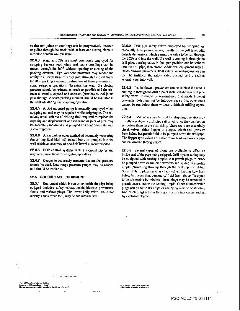
RECOMMENDED PRACTICES FOR BLOWOUT PREVENTION EQUIPMENT SYSTEMS FOR DRILLING WELLS 65
so that tool joints or couplings can be progressively lowered
or pulled through the stack with at least one sealing element
closed to contain well pressure
22.4.3 Annular BOPs arc most commonly employed for
stripping because tool joints and some couplings can be
moved through the BOP without opening or closing of the
packing element High wellbore pressures may hinder the
ability to allow passage of tool joint through closed annu
lar OP packing element limiting use of these preventers in
some stripping operations To minimize wear the closing
pressure should be reduced as much as possible and the ele
ment allowed to expand and contract breathe as tool joints
pass through spare packing element should be available at
the well site during any stripping operation
22.4.4 skid mounted pump is normally employed when
stripping out and may be required while stripping in The rel
atively small volume of drilling fluid required to replace the
capacity and displacement of each stand or joint of pipe maybe accurately measured and pumped at controlled rate with
such equipment
22.4.5trip tank or other method of accurately measuring
the drilling fluid bled off leaked from or pumped into the
well within an accuracy of one-half barrel is recommended
22.4.6 ROP control systems with associated piping and
regulators are critical for stripping operations
22.4.7 Gauges to accurately measure the annulus pressure
should be used Low range pressure gauges may be needed
and should be available
22.5 SUBSURFACE EQUIPMENT
22.5.1 Equipment which is run or set inside the pipe being
stripped includes safety valves inside blowout preventers
floats and various plugs The lower kelly valve while not
strictly subsurface tool may be run into the well
OnpyrightAmodoon PnirnIonn Inolilul
mudded by il-id undo linen. withMI
Pen reproduction or nnlovokdrg permitted without lIoono from iHS
22.5.2 Drill pipe safety valves employed for stripping are
essentially full-opening valves usually of the ball type with
outside dimensions which permit the valve to be run through
the BOPs and into the well If well is coming in through the
drill pipe safety valve in the open position can be stabbed
into the drill pipe then closed Additional equipment such as
inside blowout preventers float valves or seating nipples can
then be installed the safety valve opened and sealing
assembly run into well
22.5.3 Inside blowout preventers can be stabbed if well is
coming in through the drill pipe or installed above drill pipe
safety valve It should be remembered that inside blowout
preventer tools may not be full-opening so that other tools
cannot be run below them without difficult milling opera
tion
22.5.4 Float valves can be used for stripping operations by
installation above drill pipe safety valve or they can be run
as routine items in the drill string These tools are essentially
check valves either flapper or poppet which seal pressure
from below but permit fluid to be pumped down the drill pipe
The flapper type valves are easier to mill out and tools or pipe
can be lowered through them
22.5.5 Several types of plugs are available to effect an
inside seal of the pipe being stripped Drill pipe or tubing maybe equipped with seating nipples that pcrmit plugs to either
be pumped down or run on wiretine and landed in profile
nipple preventing flow up through the drill pipe or tubing
Some of these plugs serve as check valves halting flow from
below but permitting passageof fluid from above Designed
to be retrievable by wireline these plugs may be removed to
permit access below the seating nipple Other nonretrievable
plugs can be set in drill pipe or casing by electric or shooting
line Such plugs are run through pressure lubricators and set
by explosive charge
Sold nOT consuLTinG W000nanS
Itot Per RnonI2LlmiLitO ie44on GMT
PSC-MDL2179-O1 1114

APPENDIX AFORMS
67
Copydght nrI Pftoum nIItol
PrIdod by PbS ond IIone wth bP SIdoS7 CONSULTING WO9US32
No reprcduollcn Sr networkltispermltled sithouttoense from IHS Not or ReseIe201010110 1644U6 GMT
PSC-MDL21 79-011115
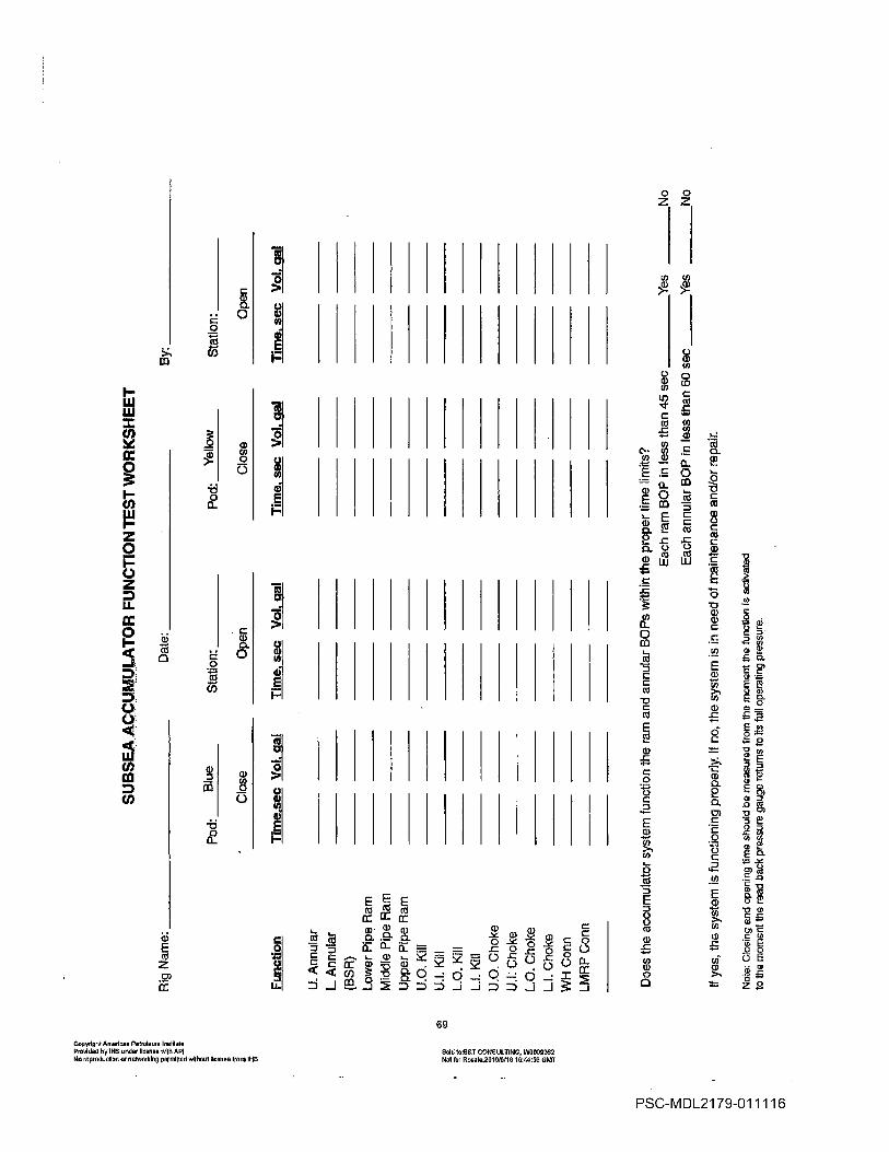
Pod
Blu
e
Function
Tim
esec
Vol
cia
Tim
esec
Vol
gal
Tim
esec
Vol
gal
Tim
esec
Vo
lgal
An
nula
r
Annula
r
BS
RLow
er
Pip
eR
am
Mid
dle
Pip
eR
am
Upper
Pip
eR
am
UO
Kill
11.1
Kill
LO
.KiII
L.f
Kill
U.O
.Choke
U.L
Choke
L.O
Choke
LI
Choke
WH
Conn
LMR
PC
onn
Does
the
accum
ula
tor
syste
mfu
nction
the
ram
and
annula
rB
OP
sw
ithin
the
pro
per
tim
elim
its
if
yes
the
syste
mis
functionin
gpro
pe
rly
If
no
the
syste
mis
inneed
of
main
tenance
and/o
rrepair
Note
Clo
sin
gand
openin
gtim
eshould
be
measure
dfr
om
the
mom
ent
the
functh
nis
activate
d
toth
em
om
ent
the
read
back
pre
ssure
gauge
retu
rns
toits
full
opera
ting
pre
ssure
Rig
Nam
e
SU
BS
EA
AC
CU
MU
LAT
OR
FU
NC
TIO
NT
ES
TW
OR
KS
HE
ET
_____________
Date
__________________________
Clo
se
By
Sta
tion
__________
Pod
Yellow
Open
Clo
se
Sta
tion
__
__
__
__
__
_
Op
en
-D
Each
ram
BO
Pin
lessth
an
45
se
c_
__
__
__
_Y
es
__
__
__
_N
o
Each
annula
rB
OP
inle
ss
tha
n6
0se
c_
__
__
__
Ye
s_
__
__
__
_N
o
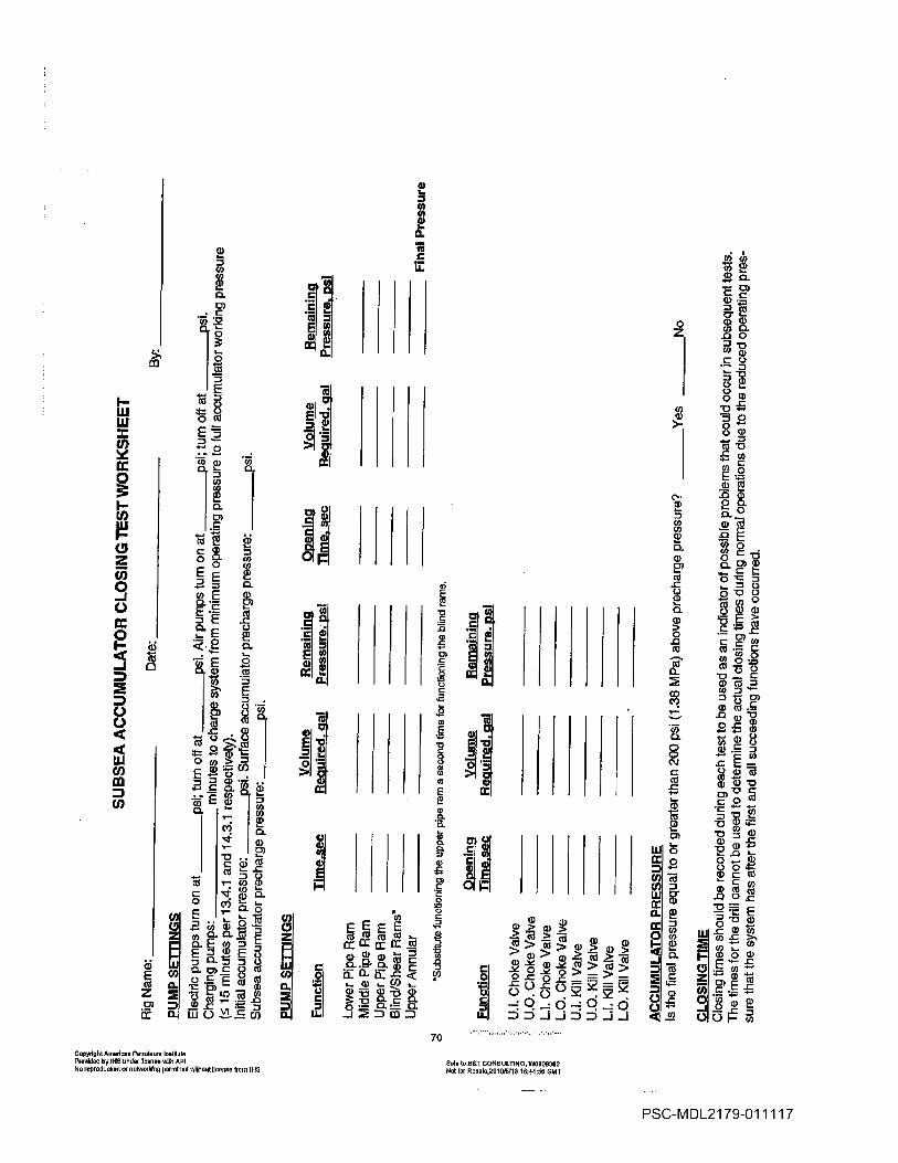
Rig
Nam
e__________________________
Date
PU
MP
SE
TT
ING
S
Ele
ctr
icpum
ps
turn
on
at
________psi
turn
off
at
________psi
Air
pum
ps
turn
on
at
________psi
turn
off
at
________psi
Charg
ing
pum
ps
_______________
min
ute
sto
charg
esyste
mfr
om
min
imum
opera
ting
pre
ssure
tofull
accu
mu
lato
rw
ork
ing
pre
ssure
15
min
ute
sper
13.4
.1and
14.3
.1re
spectively
Initia
laccum
ula
tor
pre
ssure
psL
Surf
ace
accum
ula
tor
pre
charg
epre
ssure
psi
Subsea
accum
ula
tor
pre
charg
epre
ssure
psi
PU
MP
SE
TT
ING
S
SU
BS
EA
AC
CU
MU
LAT
OR
CLO
SIN
GT
ES
TW
OR
KS
HE
ET
no
sfl
Wa
20
in OS
Se
By
Function
Low
er
Pip
eR
amM
iddle
Pip
eR
am
Upper
Pip
eR
amB
lincjfS
hear
Ram
s
Upper
An
nula
r
Yciu
rne
Rem
ain
ing
Ooenin
gV
olu
me
Rem
ain
ing
Tim
esec
Required
eel
Pre
ssurp
JT
ime
sec
Required
gal
Pre
ssure
p
Fin
al
Pre
ssu
re
Substitu
tefu
nctionin
gth
eupper
pip
em
msecond
lim
efo
rfu
nctionin
9th
eblind
ram
s
Function
Dpenin
gY
ofu
qi
Rem
ain
ing
Tim
e.s
ec
Required
gal
Pre
ssure
psi
U.l
Choke
Valv
e
U.O
Choke
Valv
e
LI
Choke
Valv
e
LO
Choke
Valv
e
U.l
Kill
Valv
e
U.O
Kill
Valv
e
LI
Kill
Valv
e
LO
Kill
Valv
e
-D Ni
cci
AC
CU
MU
LAT
OR
PR
ES
SU
RE
Isth
efinal
pre
ssure
equal
toor
gre
ate
rth
an
200
psi
1.3
8M
Pa
above
pre
charg
epre
ssure
_______Y
es
__
__
__
__
No
CLO
SIN
GT
IME
Clo
sin
gtim
es
should
be
record
ed
during
each
test
tobe
used
as
an
indic
ato
rof
possib
lepro
ble
ms
that
could
occu
rin
subsequent
tests
The
tim
es
for
the
drill
cannot
be
used
todete
rmin
eth
eactu
al
clo
sin
gtim
es
during
norm
al
opera
tions
due
toth
ere
du
ce
dopera
ting
pre
ssure
that
the
syste
mhas
after
the
first
and
all
succeedin
gfu
nctions
have
occurr
ed

SU
RF
AC
EA
CC
UM
ULA
TO
RC
LO
SIN
GT
ES
TW
OR
KS
HE
ET
Rig
Nam
e__________________________
Date
______________________
By
PU
MP
SE
TflN
GS
Ele
ctr
icpum
ps
turn
on
at
________psi
turn
off
at
________psi
Air
pum
ps
turn
on
at
________psi
turn
off
at
________psi
Charg
ing
pum
ps
--
min
ute
sto
clo
se
annula
ron
sm
allest
siz
epip
eused
min
ute
sper
12.4
.1
Initia
laccum
ula
tor
pre
ssure
________psi
Surf
ace
accum
ula
tor
pre
charg
epre
ssure
________psi
AC
CU
MU
LAT
OR
CLO
SIN
GT
ES
T
Rem
ain
ing
Functio
nT
ime
sec
Pre
ssure
psi
Low
er
Pip
eR
am__________
__________
Mid
dle
Pip
eH
amit
applicable
___________
___________
Upper
Pip
eR
am___________
___________
Blind
Ram
__________
__________
Annula
r___________
___________
11C
RV
alv
eopen
__________
__________
Anal
Pre
ssure
t5ubstitu
tefu
nctionin
gth
eupper
pip
era
msecond
tim
efo
rfu
nctionin
gth
eblind
ram
s
AC
CU
MU
LAT
OR
PR
ES
SU
RE
Isth
efinal
pre
ssure
equal
toor
gre
ate
rth
an
200
psi
1.3
8M
Pa
above
pre
charg
epre
ssure
_______Y
es
__
__
__
__
No
CLO
SIN
GT
IME
Clo
sin
gtim
es
should
be
record
ed
during
each
test
tobe
used
as
an
indic
ato
rof
possib
lepro
ble
ms
that
could
occu
rin
subsequent
tests
The
tim
es
for
the
drill
cannot
be
used
todete
rmin
eth
eactu
al
clo
sin
gtim
es
during
norm
al
opera
tions
due
toth
ere
du
ce
dopera
ting
pre
ssure
that
the
syste
mhas
after
the
first
and
all
succeedin
gfu
nctions
have
occurr
ed
-o
Does
the
accum
ula
tor
syste
mfu
nction
the
ram
sand
annula
rsw
ithin
the
pro
per
tim
elim
its
Co
Each
ram
BID
Pin
less
than
30
se
c_
__
__
__
_Y
es
__
__
__
No
Each
annula
rB
OP
inle
ss
than
30
secto
r18t4
and
45
sec
for
1814
and
gre
ate
r________
Ye
s_
__
__
_N
o
If
yes
the
syste
mis
function
pro
petly
If
no
the
syste
mis
inneed
of
main
tenance
and/o
rrepair
Mote
clo
sin
gam
es
should
be
measure
dth
em
om
ent
the
funon
isacta
ted
toth
em
om
ent
the
readback
pre
ssure
gauge
reto
ms
toIt
ofu
llopera
ting
pssu
re
Additional copies available from API Publications and Disfribution
202 682-6375
Information about API Pubiloatlons Programs and Services Is
available on the World Wide Web athttp//arww.api.org
American 1220 Street Northwest
Petroleum Washington 0.0.20005-4070
Institute 202-682-8000Order No G53003
Copyright AndIron Perreleon Indium
Peanrided by Il-IS under license ndrh API Sold IoSSrCONSULFINn3 W0509352Noreprodusllon on netoorrileg penmlrledrslrlnoonlleunse Freer IllS
Idol For Aeeele20lel5F1S le4-tSSCMT
PSC-MDL21 79-011119


![[Frontiers in Bioscience 11, 2179-2192, September 1, 2006]](https://static.fdocuments.in/doc/165x107/62356e1e67d47524e43cfd5f/frontiers-in-bioscience-11-2179-2192-september-1-2006.jpg)


