Energy Storage Technologiesease-storage.eu/wp-content/uploads/2017/01/2017.01.16_ES... · Web...
26
DRAFT – FOR PUBLIC CONSULTATION 6. Energy Storage Technologies 6.1 Mechanical Energy Storage Compressed Air Energy Storage Introduction Compressed Air Energy Storage (CAES) refers to a process in which energy is stored in the form of high pressure compressed air. A CAES system can be built to have power scales from a few kilowatts to over a few hundred megawatts and energy charge and discharge durations from a few minutes to a few days with moderate response time and good partial-load performance. Any CAES installation refers to the establishment of a system integrating different interacting components, devices, and processes. The common components of a CAES system must include compressors, expanders, and an air storage reservoir. The rest of the system components depend on the system structure and operation principles. Successful CAES implementation derives from the mid-20 th century. In 1949, S. Laval obtained a patent on using air to store power inside an underground air-storage cavern, which marked a new era of CAES applications 1 . The world’s first utility-scale CAES plant was installed and commissioned to operation by “Asea Brown Boveri (ABB)” at Huntorf, Germany, in 1978 2 . It has a rated power generation of 290 MW 3 . As an available option for peak load shifting in power grid operation and due to its relatively low cost compared to oil and gas prices through the 1980s to 1990s, CAES technology development and its industrial applications have remained attractive. In 1991, another large-scale CAES plant commenced operation in McIntosh, Alabama, US 4 . The 110 MW plant, with a storage capacity of 2,700 MWh, is capable of continuously delivering its full power output for up to 26 hours. The plant is used to store off-peak power, generate peak power, and 1 B. J. Davidson, et al., “Large-scale electrical energy storage”, Physical Science, Measurement and Instrumentation, Management and Education Reviews, IEE Proceedings A, vol. 127, no. 6, pp. 345–385, 1980. 2 B. J. Davidson, et al., “Large-scale electrical energy storage” 3 Ibid. S. Succar, R.H. Williams, “Compressed air energy storage: theory, resources, and applications for wind power”, technical report, Energy Systems Analysis Group, Princeton Environmental Institute, Princeton University, 2008. 4 Ibid. 1 EASE/EERA European Energy Storage Technology Development Roadmap
Transcript of Energy Storage Technologiesease-storage.eu/wp-content/uploads/2017/01/2017.01.16_ES... · Web...

DRAFT – FOR PUBLIC CONSULTATION
6. Energy Storage Technologies 6.4 Mechanical Energy Storage
Compressed Air Energy StorageIntroductionCompressed Air Energy Storage (CAES) refers to a process in which energy is stored in the form of high pressure compressed air. A CAES system can be built to have power scales from a few kilowatts to over a few hundred megawatts and energy charge and discharge durations from a few minutes to a few days with moderate response time and good partial-load performance. Any CAES installation refers to the establishment of a system integrating different interacting components, devices, and processes. The common components of a CAES system must include compressors, expanders, and an air storage reservoir. The rest of the system components depend on the system structure and operation principles. Successful CAES implementation derives from the mid-20th century. In 1949, S. Laval obtained a patent on using air to store power inside an underground air-storage cavern, which marked a new era of CAES applications1. The world’s first utility-scale CAES plant was installed and commissioned to operation by “Asea Brown Boveri (ABB)” at Huntorf, Germany, in 19782. It has a rated power generation of 290 MW3. As an available option for peak load shifting in power grid operation and due to its relatively low cost compared to oil and gas prices through the 1980s to 1990s, CAES technology development and its industrial applications have remained attractive. In 1991, another large-scale CAES plant commenced operation in McIntosh, Alabama, US4. The 110 MW plant, with a storage capacity of 2,700 MWh, is capable of continuously delivering its full power output for up to 26 hours. The plant is used to store off-peak power, generate peak power, and provide spinning reserves.5 The common feature of these two CAES plants is that they all involve burning a fossil fuel – natural gas – in their electricity generation process.
Maturity of technologyThe Huntorf and McIntosh CAES power plants demonstrate the maturity of the first and second generation CAES technology. The current development focuses on the third generation CAES technology which aims to avoid involving fossil fuel by using the heat generated through the compressing process6.
1 B. J. Davidson, et al., “Large-scale electrical energy storage”, Physical Science, Measurement and Instrumentation, Management and Education Reviews, IEE Proceedings A, vol. 127, no. 6, pp. 345–385, 1980.2 B. J. Davidson, et al., “Large-scale electrical energy storage”3 Ibid. S. Succar, R.H. Williams, “Compressed air energy storage: theory, resources, and applications for wind power”, technical report, Energy Systems Analysis Group, Princeton Environmental Institute, Princeton University, 2008.4 Ibid.5 S. Succar, R.H. Williams, “Compressed air energy storage: theory, resources, and applications for wind power” H. Chen, T. N. Cong, W. Yang, C. Tan, Y. Li, and Y. Ding, “Progress in electrical energy storage systems: A critical review”, Progress in Natural Science, vol. 19, no. 3, pp. 291–312, 2009.
1EASE/EERA European Energy Storage Technology Development Roadmap

DRAFT – FOR PUBLIC CONSULTATION
In 2010, RWE Power, General Electric, Züblin and the German Aerospace Centre (DLR) started working on the world’s first large-scale Advanced Adiabatic (AA-CAES) demonstration plant project, in which the heat generated in the compression stage is stored in a thermal storage medium and used at the expansion process7. However, this project was put on hold due to the lack of clarity about its economic and business viability. Meanwhile, some R&D work in small-scale CAES has attempted to use CAES to replace chemical batteries in some applications. US-based LightSail Energy Ltd. patented and developed a CAES technology which came very close to achieving isothermal compression and expansion (I-CAES) and which captures the heat from the compression process by spraying water (with water drop sizes at the nano-scale) for efficient heat absorption and storage. The stored heat is then added to the compressed air during expansion using the same technology8. A number of demonstration projects are currently on-going, indicating that the technology for CAES with no fossil fuel is available. However, widespread deployment requires market maturity and improvement in round trip efficiency.
ApplicationsIn addition to the existing uses of CAES in Huntorf and Alabama, CAES can also provide a wide range of attractive system services owing primarily to the impressive ramp rates associated with the technology. CAES is capable of providing system services such as, but not limited to, inertial response (in both compression and expansion), operating reserve (primary, secondary and tertiary), fast frequency response, fast post fault active power recovery, dynamic reactive response, and steady state reactive power. CAES’ ability to provide such services will be a key enabler for permitting higher levels of renewable energy and reduce wind power curtailment while maintaining power system stability. A wide range of applications of CAES is outlined in Table 13.Table 13 Application potentials of CAES related technology9
Application area
Characteristics( [18, 50, 61 ~ 65])
Suitable or potential CAES related technology
Power quality <1MW, response time (milliseconds, <1/4 cycle), discharge duration (milliseconds to seconds)
Hybrid systems with small-scale CAES and battery or supercapacitor or other EES technologies with fast response
Energy management
Large-scale (>100 MW), medium/small-scale (<100 MW), response time (minutes), discharge duration (up to days)
Large-scale energy management (large-scale CAES); Small-scale energy management (small-scale CAES, LAES)
Renewable 100 kW-40 MW, response time Multi-scale CAES, hybrid systems
6 X. Luo, J. Wang, M. Dooner, J. Clarke and C. Krupke, “Overview of current development in compressed air energy storage technology”, Energy Procedia, Vol. 62. pp.603-611, 2014.7 RWE power, ADELE – Adiabatic compressed-air energy storage (CAES) for electricity supply, ADELE Brochure, 2016. https://www.rwe.com/web/cms/mediablob/en/391748/data/364260/1/rwe-power-ag/innovations/Brochure-ADELE.pdf 8 Lightsail Energy Ltd, 2016. http://www.lightsail.com 9 X. Luo, J. Wang, “Overview of the current development on compressed air energy storage”, EERA Report, 2016. http://integratedenergystorage.org. Not all characteristics outlined in this reference have been included in the table. These are not the only characteristics CAES is capable of providing, as the characteristics are dependent on the system operators’ requirements. Examples have been added to the table.
2EASE/EERA European Energy Storage Technology Development Roadmap

DRAFT – FOR PUBLIC CONSULTATION
back-up power (seconds to minutes), discharge duration (up to days)*
with CAES and capacitor or others with fast response may need, possible LAES
Emergency back-up power
Up to 1 MW, response time (milliseconds to minutes),discharge duration (up to ~24 hours)*
Possible small-scale CAES, hybrid systems with small-scale CAES and other technologies with fast response
Time shifting 1 MW-100 MW and even more, response time (minutes), discharge duration (3-12 hours)
Multi-scale CAES and LAES
Peak shaving 100 kW-100 MW and even more, response time (minutes), discharge duration (hour level, <10hours)
Multi-scale CAES and LAES
Load levelling up to several hundreds of MW, response time (minutes), discharge duration (up to ~ 12hours and even more)
Multi-scale CAES, possible LAES
Black Start Up to rated output (depending on stored energy) response time minutes
Multi- scale CAES
Inertial Response
Provided in both compression and expansion
Multi- scale CAES
Frequency Response
XX MW – XX MW, range dependent on system operator response requirements
Multi- scale CAES
Reactive Power Response
XX MVar – XX MVar, range dependent on system operator response requirements
Multi- scale CAES
Operating Reserve
XX MW – XX MW, range dependent on system operator response requirements
Multi- scale CAES
*Note that the limits can vary significantly depending on individual system operators’ reserve response times and requirements.
SET-Plan targetsTable 14 lists the theoretically highest achievable efficiency for all the major segments in a CAES system. From the table, it can be seen that the highest efficiency that can be achieved theoretically is 81.9% to date. Table 14. The theoretical values of the maximum energy efficiency Efficiency System
EfficiencyCompression Efficiency
Heat storage Efficiency
Cold storage efficiency
Storage efficiency
Expansion Efficiency
Theoretical value
81.9% 91% 99% 99% 99.8% 92%
The target should be to achieve the following efficiency by 2030:2016 - 2020 2020 – 2030Achieving system efficiency of 60 – 65% Achieving system efficiency around 70%
3EASE/EERA European Energy Storage Technology Development Roadmap

DRAFT – FOR PUBLIC CONSULTATION
4EASE/EERA European Energy Storage Technology Development Roadmap

DRAFT – FOR PUBLIC CONSULTATION
Gaps between targets and present performanceAs described above, the main weakness of CAES is its relatively low energy efficiency. From the current large scale CAES (> 1 MW) reported, the best round-trip efficiency achieved is around 53%. The main target for CAES technology development is to improve the CAES system efficiency to reduce the gap between the practical system efficiency and the theoretically achievable efficiency.
Research PrioritiesTo further the development of CAES technology, the following research challenges need to be addressed, in the order of priority from high to low:
1. Innovation in turbo machinery design and manufacturing: technical innovations and technology breakthroughs are essential, especially for high-pressure compressor and turbine technologies, such as developing improved sealing methods for compression and expansion machinery to suppress internal leakage and discovering approaches to minimise losses associated with secondary flows in compressors and turbines.
2. Formation of salt caverns: salt caverns for compressed air storage can be developed through solution mining techniques which can provide a low cost and reliable methodology. To make the process economically viable, the process should maximise the size/volume of the caverns for each salt mining well drill. Costs related to the location of the energy source relative to the storage site(s) need to be examined in the techno-economic analysis.
3. Aboveground manufactured reservoir: above ground CAES is possible in steel pipes. However, these systems are currently prohibitively expensive. New materials for these reservoirs, such as carbon fibre or glass fibre, could be the next breakthrough technology which could allow aboveground CAES to compete with the costs of underground CAES. To make this happen, more understanding of fibre meshing or weaving is needed to improve efficiency and reduce costs.
4. Thermal storage for improvement of round trip efficiency: the low efficiency of CAES results from the heat losses in the compression and expansion modes, air leakage throughout the whole CAES system, and internal energy losses due to the air compressibility. To improve CAES round trip efficiency, the following research is required:
i. suitable thermal storage procedure and facility design to maximise the utilisation of thermal energy stored, such as high-pressure thermal storage;
ii. the individual components or devices working at their optimal status do not mean the whole system is in its optimal status due to complicated coupling effects.
5. Integrated technologies: integrated utilisation of energy through the whole process, e.g. through the coupling of CAES with waste heat or district heating and cooling, can increase the round trip efficiency as the energy losses can be recovered via the integrated process.
Recommendations for research funding, infrastructure and incentives
5EASE/EERA European Energy Storage Technology Development Roadmap

DRAFT – FOR PUBLIC CONSULTATION
Research Funding: the priority should be given to turbo machinery research; that is, efficient large scale compressor and expander technologies as well as high efficient low cost thermal storage technologies. In addition, funding will be required for prefeasibility/feasibility studies to identify optimal locations, plant configuration, system requirements, and business models for CAES facilities.Infrastructure: it is urgent to provide the essential financial support to complete building CAES plants or to complete projects like the ADELE10 one in Germany, so that essential knowledge and experience can be gained from CAES plants construction and operation.Incentives: favourable policy needs to be in place to ensure that newly built CAES plants are able to maintain their operations. Appropriate regulatory treatment needs to be put in place to ensure that revenues are sufficient to incentivise investment in CAES technology and deployment of CAES facilities.
10 RWE power, ADELE – Adiabatic compressed-air energy storage (CAES) for electricity supply, ADELE Brochure, 2016. https://www.rwe.com/web/cms/mediablob/en/391748/data/364260/1/rwe-power-ag/innovations/Brochure-ADELE.pdf
6EASE/EERA European Energy Storage Technology Development Roadmap

DRAFT – FOR PUBLIC CONSULTATION
Flywheel Energy StorageIntroductionThis kinetic energy storage system is composed of a flywheel driven by an electrical machine (different types of technologies are considered, mainly permanent magnets and reluctance machines), able to work as a motor or a generator, and some power electronics to drive the machine, connecting to the electric grid or the load. When the electric machine (acting as a motor) exerts a positive torque T to the flywheel with moment of inertia J, it increases its rotation speed at a rate of T/J, until it reaches maximum velocity, storing a given kinetic energy and getting power from the grid or the load through the power electronics converter. At this stage the energy can be maintained constant at the flywheel by supplying the idle losses in the machine. To release the energy, the electrical machine (acting as a generator) applies a negative torque –T to the flywheel, braking it at a rate – (T/J) and pumping the energy back to the grid or the load to which it is connected.Two main groups of technologies are being developed for flywheels: metallic and compound materials. The first are relatively slow (below 10,000 rpm). The wheel is metallic and often has magnetic levitation systems which offset its weight. These slow storage systems are, in theory, simpler in a technological sense. Their main use is in stationary applications, where their weight is not an obstacle. There is also another family of flywheels: rapid flywheels whose velocity can achieve 50,000 rpm and which use wheels made of composite materials, such as carbon fibres, which offer high levels of mechanical resistance and low density. The elevated cost of the wheel and the difficulty of manufacture mean that its use is restricted in general to applications of limited energy in which the system price is not a critical issue. The greater densities per mass unit are achieved using compound materials (ideally carbon fibre). But if the concern is to achieve energy per volume unit, metals such as steel can be as effective as fibres, while remaining much more economical.Flywheels are a fast-reacting energy storage technology characterised by high power and energy density, the possibility to decouple power and energy in the design stage, a large number of life-cycles, the possibility to be installed in any location (even on board applications are being considered), and high power but usually low energy compared with some other energy storage devices. Moreover, the operation of flywheels is less dependent on the external temperature than other storage technologies (e.g., batteries). State of charge (SoC) is also easy to determine since it is directly related to the rotational speed. Finally, the dynamic response is fast and not temperature dependent.
Maturity of technologyFlywheel is a mature technology, which is completely introduced in the industrial market. More than 20 manufacturers have been identified and many research centres are focused on this technology as well developing prototypes. However, some technological aspects need to be improved both in manufacturing and equipment cost in order to be competitive with other energy storage solutions. Technology Readiness Level (TRL) has reached the maximum level of 9 in some commercial products. However, many alternative solutions or prototypes are situated in the TRL range between 3 and 8.
7EASE/EERA European Energy Storage Technology Development Roadmap

DRAFT – FOR PUBLIC CONSULTATION
ApplicationsFlywheels are suited to a number of applications, including:
1. Transportation, which can help reduce CO2 emissions, increase the efficiency, reduce the power consumption peaks, enable energy savings, and contribute power line voltage stabilisation. Flywheels can be applied in electric and hybrid automobiles (both in electric cars and buses), light trains, underground transportation, and ferries.
2. Supporting the integration of renewable energy generation by contributing to grid stability, frequency regulation, and voltage support.
3. Industry applications, to ensure power supply or increase the efficiency. Flywheels can be applied for cranes and elevators and can serve as a UPS.
A continuous study of the potential applications could reveal new and interesting uses, increasing the industrial market for companies developing flywheels. Moreover, recent research studies have demonstrated that the use of flywheels not substituting but completing the operation of other energy storage technologies, such as batteries, can increase their life cycle (hybrid energy storage).
8EASE/EERA European Energy Storage Technology Development Roadmap

DRAFT – FOR PUBLIC CONSULTATION
Table 15: SET-Plan targetsCurrent performance Target 2030 Target 2050
High cycle life >100000 cyclesPower: 100 – 1500 kWEnergy: 0,5 – 50 kWhRoundtrip efficiency: 80-90 %Cost: 500-3000 €/kWh and 1000-2000€/kW (depending on the power and energy levels)
Reduced friction, higher rotation speed for higher energy storage (>10kWh)Stronger materials (composite)Rotor manufacturing cost reduction <3000 €/kWhLarge scale demonstration sitesDevelopment of competitive magnetic bearings
Higher energy storage density >100Wh/kgCost reduction < 350€/kWh
Gaps between targets and present performanceThe gaps between the SET-Plan targets and present performance can be broken down across the different parts of the device:
Flywheel disc: developing flywheels with a higher energy density at a lower cost by improving the manufacturing procedure (especially carbon composite and glass fibre flywheels but also metallic) is imperative.
Electrical machines: there is a need for economically reliable manufacturing, a high-quality torque to reduce the bearings requirements, and low machine losses to ensure continuous operation with a simple cooling system.
Bearings: since the system is usually rotating at a very high speed (10,000 rpm) while supporting a high axial force, conventional bearings are not always suitable for use. Magnetic bearing is a widespread technology for high speed systems but more research is still required to ensure robustness and stable operation for use in flywheels.
Power electronics: the speed range of the flywheel is quite large and the machine has to be capable of supplying and absorbing a certain amount of power. A power electronic converter manages the power behaviour of the system, both towards the machine and the electric grid or the load, with a high performance and low witching and conduction losses. Moreover, there are additional advantages through using a power converter since it can be used as STATCOM or any other type of grid support, with a minor increase in the complexity and cost.
Digital control and communications: digital control provides a powerful platform to achieve a high performance in fast energy storage systems together with power electronics, enabling the implementation of complex control strategies and a high performance drive.
Security case or frame: the safety conditions of the flywheel must be closely studied, particularly regarding the design of the external case.
9EASE/EERA European Energy Storage Technology Development Roadmap

DRAFT – FOR PUBLIC CONSULTATION
Research PrioritiesSolving the gaps implies advances for each above-mentioned component:
1. Flywheel disc: research on better materials for carbon and glass fibre composite flywheels (high density) should be carried out to reduce the total cost and increase energy density.
2. Electrical machines: high performance machines are required to be used in these devices and although permanent magnet machines seemed to be the best option, the high cost of the magnets has redirected the research towards new machine concepts with fewer magnets.
3. Bearings: faster control systems are being developed to improve the bearings response and more efficient actuators are being used to increase the performance of the complete system. Magnetic and superconducting bearings need to be studied as a solution for high speed flywheels. The lower complexity and energy losses of the superconducting bearings allow a time decay of the stored energy in the range of a 20% in 200 hours. Improvements in the reliability of the cryogenics will lead to a more competitive system11.
4. Power electronics: increase the added value of the power electronics in an energy storage system, ensuring the robustness and reliability and leading to a higher roundtrip efficiency.
5. Digital control and communications: digital control and fast communication improvements permit operating the system with guarantees of robustness, being able to analyse a lot of variables, maintaining a complete diagnosis of the application from anywhere, and facilitating integration with other subsystems.
11 George Roe, Boeing Flywheel Energy Storage Technology, 2012.10
EASE/EERA European Energy Storage Technology Development Roadmap

DRAFT – FOR PUBLIC CONSULTATION
Recommendations for research funding, infrastructure and incentivesFunding programmes and incentives should be focused on researching particular technologies involved in flywheels, as well as how to integrate these technologies and test their reliability. Demonstration tests are essential for further investments in the technology. Devices should be tested in demonstration sites where the operation is close to the final application. Programmes and institutions should favour experimental tests in sites such as electric grid areas. Finally, a better knowledge and wider experience in prototypes would reduce the security costs. Research centres and companies should work together to integrate flywheels in facilities where fast energy storage is required in order to test its reliability.
11EASE/EERA European Energy Storage Technology Development Roadmap

DRAFT – FOR PUBLIC CONSULTATION
Liquid Air Energy StorageIntroductionLiquid Air Energy Storage (LAES), not to be confused with CAES, is an energy storage technology that uses liquid air as an energy vector. The technology benefits from mature supply chains and processes, reducing technology risk. In addition, the technology does not use scarce or toxic components, has a long cycle life, and is well suited for long duration applications. A LAES system comprises a charging system; up to three energy stores (a main liquid air store, an optional compression heat store, and an optional cold store for high grade cold recovery); and a discharging system. The charging system is an industrial air liquefaction plant where electrical energy is used to reject heat from ambient air drawn from the environment, generating liquid air (“cryogen”). The liquid air is stored in an insulated tank at low pressure, which functions as the main energy store. When power is required, liquid air is drawn from the tank, pumped to high pressure, and evaporated. This produces gaseous air that can be used to drive a piston engine or turbine to do valuable work that can be used to generate electricity. The stored compression heat can be used to increase the work output. Alternatively, (waste) heat from an industrial process, a gas turbine or other conventional power station can be used to heat up the air before expansion. The stored cold can be used to reduce the power consumption of the liquefaction process.
Figure 12: LAES mode of operation
12EASE/EERA European Energy Storage Technology Development Roadmap

DRAFT – FOR PUBLIC CONSULTATION
Maturity of technologyThe LAES technology concept was first proposed by researchers at the University of Newcastle upon Tyne (UK) in 1977 for peak shaving of electricity grids12. This work led to subsequent development of the technology particularly by Mitsubishi Heavy Industries and Hitachi (Japan) and Highview Power Storage in collaboration with the University of Leeds (UK). The world’s first demonstration plant (350 kW/2.5 MWh) was built by Highview Power Storage and is currently located at the University of Birmingham Campus and it is the only one that has an actual liquefier for liquid air production (about 30 tons/day capacity). The overall process has been demonstrated by Mitsubishi Heavy Industries Ltd and Highview Power Storage in two pilot scale plants. Mitsubishi Heavy Industries demonstrated the LAES technology in the late 1990s in a pilot scale with roughly 2 MW power output with an integrated gas turbine system13. Mitsubishi Hitachi Power Systems Europe and the Linde Group have been jointly developing the LAES technology since 2012. They have successfully developed a “generation 1” system based on commercially available components, thus avoiding the need for lengthy product development, which can be built today. The system can be a stand-alone plant with integrated heat storage or it can be retrofitted to an existing simple cycle gas turbine power plant. The gas turbine can still be operated as a separate open cycle unit without the charging/discharging operation. In this case the plant functions as a pure peaking unit14. There is also significant integration potential into industrial processes, such as utilisation of waste heat or waste cold to increase the plant efficiency and the flexibility of the industrial process.Meanwhile, Highview has developed a 5 MW/15 MWh pre-commercial demonstrator connected at distribution level. The plant is located alongside a landfill gas generation plant in greater Manchester and is expected to be commissioned in the second half of 2016. In addition to providing energy storage, the plant will convert low-grade waste heat to power. The project will demonstrate the LAES technology, providing balancing services and supporting the local grid during the winter peaks. The completion of this project will take the technology’s TRL from 7 to 9 as the system will be proven to work in an operational environment.Additionally, the Birmingham Centre for Cryogenic Energy Storage at the University of Birmingham is currently working to further improve the round trip efficiency of LAES. The main research areas are: development of novel materials for high performance heat and cold storage, development of novel thermodynamic cycles and generation processes, systems integration, control, and optimisation for LAES.
ApplicationsLAES is suitable for many applications, including:
12 E.M. Smith, BSc, PhD, CEng, MIMechE, “Storage of Electrical Energy Using Supercritical Liquid Air. Proceedings of the Institution of Mechanical Engineers”, June 1977, 191: 289-298.13 K. Kishimoto, K. Hasegawa, T. Asano, “Development of Generator of Liquid Air Storage Energy System”, Mitsubishi Heavy Industries Ltd., Technical Review Vol. 35 No. 3 (1998), 117-20.14 B. Stöver, A. Alekseev, C. Stiller, “Liquid Air Energy Storage (LAES) - Development Status and Benchmarking with other Energy Storage Technologies”, Power Gen Europe 2014, Cologne. S. Wu, C. Bergins, B. Stöver, J. Naumovitz, C. Stiller, A. Alekseev, “Liquid Air Energy Storage – A Flexible Solution for Grid Scale Applications”, Power Gen Internationel 2014, Orlando.
13EASE/EERA European Energy Storage Technology Development Roadmap

DRAFT – FOR PUBLIC CONSULTATION
Renewables integration: LAES can support renewables integration by absorbing excess energy, thereby reducing curtailment.
Network reinforcement deferral: LAES can be installed near demand centres, reducing the need to deploy additional cables to serve local peak demand. Storage can act as an alternative or supplement to new transmission and distribution capacity. Using LAES in this application would optimise network asset utilisation as the storage system would charge for most of the night using the network transport capacity when it is less congested, and it would alleviate grid congestion at peak times by providing power at local level.
Daily/weekly balancing: LAES can be used to optimise electricity bills by charging at times of low prices and discharging when prices are high.
Security of supply (capacity provision): LAES provides flexible peaking capacity. Long duration systems, such as LAES, are able to contribute to security of supply to a greater extent than short-duration storage devices.
Frequency control, reserve and other ancillary services: LAES can contribute to grid stability by responding to imbalances in electrical energy production and consumption. In addition, LAES can provide natural system inertia.
Black start: a LAES system can provide capacity and energy after a system failure (blackout).
Improve energy efficiency in LNG regasification terminals: LAES can harness waste cold from the regasification of liquid natural gas to produce liquid air which is then used to produce electricity, enhancing overall energy efficiency.
LAES can be used to increase the flexibility of conventional power plants by lowering the minimal load and increasing the maximal load due to connections between the thermodynamic processes.
Table 16: SET-Plan targetsCurrent performance Target 2030 Target 2050
Demonstrated at pilot and pre-commercial scale – 5MW storage
Full commercial scale demonstration – 15 to 50MW /500MWh storage scale
100 MW/GWh storage scale
Round trip efficiency (RTE) ~20% at pilot scale; 50-60% (predicted) for stand-alone commercial scale LAES; potential of >65% by utilisation of waste heat
Increase round trip efficiency up to 60-70% for standalone systems and much higher e.g. ~ 90%+ through harnessing of waste heat from thermal plants/industrial processes and waste cold from industrial processes and LNG terminals
Round trip efficiency 70%-80% for standalone systems through improving efficiency of liquefaction process, and novel thermodynamic cycles, and a higher ~100% through harnessing of both waste heat and waste cold from thermal plants/industrial processes and LNG terminals
250-600 €/kWh or 2000-3500€/kW (LAES size dependent)
Cost reduction: 200-400 €/kWh or 1500-2500 €/kW (LAES size dependent)
Mature LAES costs: <200€/kWh or < 1000 €/kW
Little attention paid on developing new materials and
Advanced materials & devices for heat storage (from
Optimal integration, operation, and management
14EASE/EERA European Energy Storage Technology Development Roadmap

DRAFT – FOR PUBLIC CONSULTATION
devices for enhanced performance of LAES
compressors and intermittent sources of waste heat) and cold storage for cold recycle; reduction of parasitic losses from compressors, cryogenic pumps and expanders
of LAES in low carbon grid environment
Gaps between targets and present performanceLAES extensively uses commercially available components which make the technology positioned near market conditions. However, key components, operating conditions, and costs can be further improved to reach higher performances and provide better business cases. The technology gaps – divided into the different aspects of LAES - are:
High investment costs: there is a need to identify and quantify cost reduction drivers such as modularisation and development of ad hoc components.
Round trip efficiency (RTE): thermal energy storage materials and systems have to be thoroughly studied and optimised for LAES.
RTE: minimisation of required compression work during charge and maximisation of power output during discharge is crucial to increase round-trip efficiency of LAES.
RTE: an improved purification unit can help improve round trip efficiency of LAES.
RTE: integration of LAES with conventional plants, as it has the potential to increase overall efficiency. Comprehensive integration studies and full scale demonstration should be implemented.
Missing optimal operation and dispatching of LAES plants: complete system analyses and optimal integration with the grid are needed to achieve the best technological benefit, maximise revenues, and improve business cases for LAES.
Research PrioritiesThe following research priorities will be key to support the development of cost-effective LAES technologies:
1. Intense thermal energy storage (TES) materials, devices and systems research will be necessary to achieve substantial improvements in storing heat and cold during charge and discharge processes of LAES. Research should be directed at improving cycling operation of TES systems, increasing energy storage density, and minimising costs.
2. Research should be conducted to maximise performance of cryogenic pumps and compressors for LAES. Cryo-pumps that can achieve optimal pressure for the LAES discharge process should be sought while solutions for removal and storage of heat of compression should be developed for the compression stages.
3. Exploratory research on advanced air purification units is recommended. Removal of CO2, humidity, Argon, etc. by adsorption phenomena could represent an extra source of heat/cold storage in LAES. However, novel cost
15EASE/EERA European Energy Storage Technology Development Roadmap

DRAFT – FOR PUBLIC CONSULTATION
effective materials and design should be developed to exploit this opportunity.
4. Development of novel cycles for the discharge process. Currently liquid air is directly expanded through turbomachinery to generate power output. Novel indirect combined cycles have the potential of increasing LAES round trip efficiency. In particular, Indirect Rankine cycles with cryogenic fluids such as CO2, CH4 and C3H8 should be investigated and demonstrated at pilot scale.
5. Detailed integrated LAES-conventional plants design should be developed. LAES has the potential to exploit streams of waste heat from conventional power plants and industrial processes. Detailed studies and full-scale demonstration for coal plants, open cycle gas turbines, and diesel generators should be conducted to fully show LAES’s potential and provide business cases.
6. Best operation and dispatching strategies for LAES plants should be researched. Optimal integration of LAES into the grid will strongly depend on installation locations, the market framework, and regulation. A lack of tailored operational strategy could potentially lead to missed revenues and missed technical benefits for the energy system. Thus, a range of operation strategies should be developed for current and future market scenarios anticipating the role of LAES in low carbon grids. Particular attention should be given to the mutual interactions which may arise when LAES integrates with other conventional power plants; as off-design conditions may arise, optimal operations should be sought to achieve maximum benefit from the integrated power generation system. The enhancement of LAES response time through the integration of spin-gen technology could also be studied.
Recommendations for research funding, infrastructure and incentivesLAES requires support and industrial uptake for further technical development and to enhance the market readiness level. Industrial-academic consortiums should be supported to design, implement, and operate full-scale LAES demonstrators in multiple technical/economic environments. Strong support for academic research in new materials, components and devices, and novel system configurations will be required to maximise LAES performance and reduce overall costs. Similarly, adequate regulatory aspects and sound market conditions are necessary for the large-scale industrial uptake of LAES.
16EASE/EERA European Energy Storage Technology Development Roadmap

DRAFT – FOR PUBLIC CONSULTATION
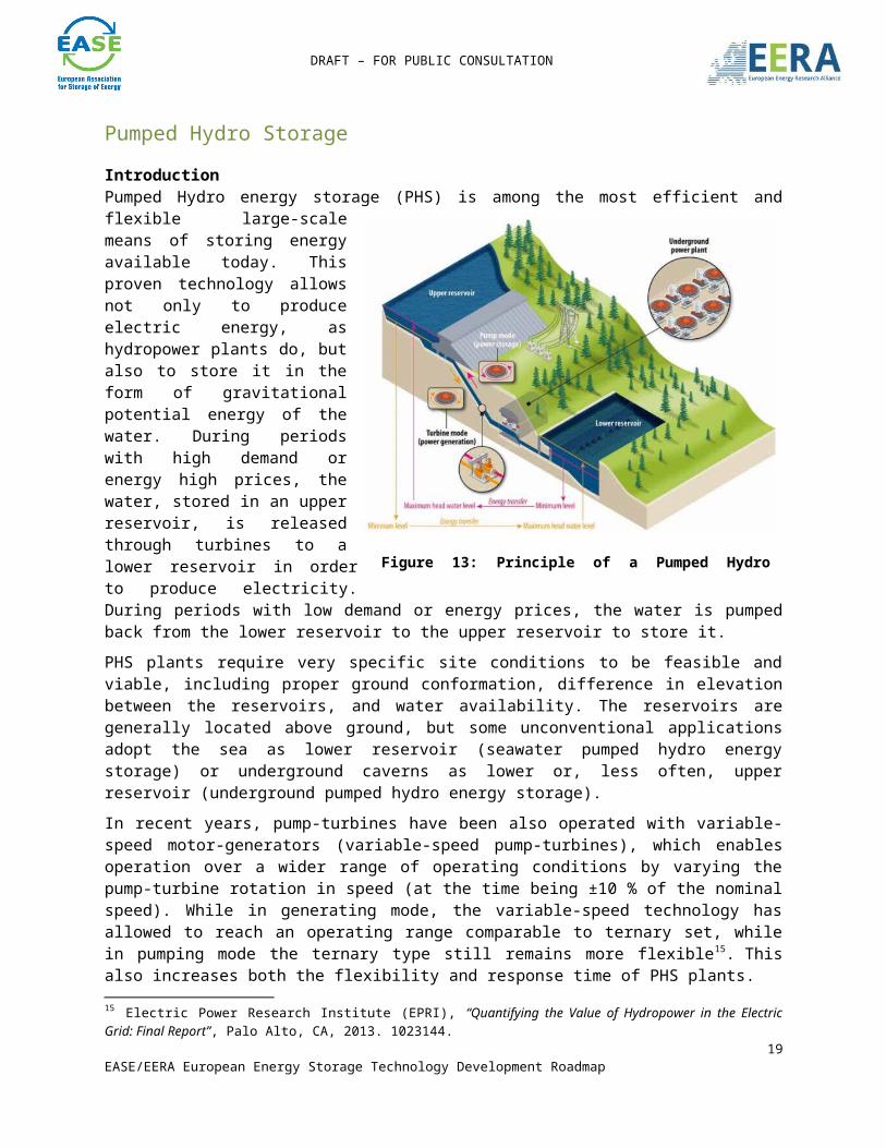
Pumped Hydro Storage IntroductionPumped Hydro energy storage (PHS) is among the most efficient and flexible large-scale means of storing energy available today. This proven technology allows not only to produce electric energy, as hydropower plants do, but also to store it in the form of gravitational potential energy of the water. During periods with high demand or energy high prices, the water, stored in an upper reservoir, is released through turbines to a lower reservoir in order to produce electricity. During periods with low demand or energy prices, the water is pumped back from the lower reservoir to the upper reservoir to store it.PHS plants require very specific site conditions to be feasible and viable, including proper ground conformation, difference in elevation between the reservoirs, and water availability. The reservoirs are generally located above ground, but some unconventional applications adopt the sea as lower reservoir (seawater pumped hydro energy storage) or underground caverns as lower or, less often, upper reservoir (underground pumped hydro energy storage).In recent years, pump-turbines have been also operated with variable-speed motor-generators (variable-speed pump-turbines), which enables operation over a wider range of operating conditions by varying the pump-turbine rotation in speed (at the time being ±10 % of the nominal speed). While in generating mode, the variable-speed technology has allowed to reach an operating range comparable to ternary set, while in pumping mode the ternary type still remains more flexible15. This also increases both the flexibility and response time of PHS plants.
Maturity of technologyPHS is undoubtedly the most mature large-scale energy storage technology. Today, in Europe, this technology represents 99 % of the on-grid electricity storage16. PHS has long been the standard solution for peak shifting in Western Europe, where inexpensive nuclear power is used to supply base load demand and to pump water to the upper reservoir of PHS plants during periods of low demand. It is now
15 Electric Power Research Institute (EPRI), “Quantifying the Value of Hydropower in the Electric Grid: Final Report”, Palo Alto, CA, 2013. 1023144.16 Electric Power Research Institute (EPRI), “Electric Energy Storage Technology Options: A White Paper Primer on Applications, Costs and Benefits”, Palo Alto, CA, 2010.
17EASE/EERA European Energy Storage Technology Development Roadmap
Figure 13: Principle of a Pumped Hydro Storage plant

DRAFT – FOR PUBLIC CONSULTATION
becoming increasingly common to manage the fluctuations variable RES supply in North Western Europe using PHS17. PHS plants are equipped with hydraulic, mechanical, electrical, and in some cases power electronics equipment, most of which have already reached a TRL of 9 (actual system proven in operational investment). The power of PHS plants ranges from approximately 20 to 500 MW. The most typical values are between 200 and 350 MW, with a storage capacity of 4 to 24 hours at full load for closed-loop PHS and depending on the upper reservoir dimensions for open-loop PHS. PHS plants are generally installed in mountainous or hilly areas where heads of 75-1500 metres can be obtained. PHS holds excellent grid connection properties, as illustrated in table 17 and figure 14, below.Table 17 – PHS features (VS = variable-speed, TS = Ternary Set)
General Performances
50 to 500 MW200 to 350 MW
Output/InputMost Typical values
>> 8 hours full load Storage capacity75 to 1500 m~100 to ~600m
Head RangeSingle stage reversible pump-turbine
> 80% Cycle efficiencyReaction Time ~15 s 50% to 100% Generation
< 2 min 0% to 100% Generation~ 1 min (TS) / ~4 min (VS)
0% to 100% Pumping
~ 1 min (TS) / ~8 min (VS)
100% Generation to 100% Pumping
Ancillary Services 15% (TS) / 25% (VS) to 100%
Production adjustment range
~0% (TS) / 70% (VS) to 100%
Pumping power adjustment range
Reactive power, Primary frequency response, Black start capability
Since conventional PHS plants can only regulate their power in generation mode, their operation in pumping mode is less flexible. Therefore, new technologies are being developed to enhance the operational flexibility of PHS plants18. Although the vast majority of PHS plants installed in Europe are fixed-speed, there is a large potential to convert existing fixed-speed plants (many of which require refurbishment) to variable speed19. 17 eSTORAGE: Potential for conversion of classical PSP to variable speed units in EU15, Norway and Switzerland, April 2016. http://www.estorage-project.eu/wp-content/uploads/2013/06/EXTRACT-of-eStorage-D4.1-Potential-for-conversion-of-classical-PSP-to-variable-speed-units.pdf18 eSTORAGE: Potential for conversion of classical PSP to variable speed units in EU15, Norway and Switzerland, April 2016. http://www.estorage-project.eu/wp-content/uploads/2013/06/EXTRACT-of-eStorage-D4.1-Potential-for-conversion-of-classical-PSP-to-variable-speed-units.pdf 19 L. Lenhard, A. Neto, O. Teller, H. van de Vegte: Developing Cost-Effective, Flexible, Reliable GWh-scale Energy Storage – An eStorage Project Update, 2015. http://www.estorage-project.eu/wp-content/uploads/2013/06/Hydro2015_Alstom_DNVGL_eStorage-Projects-Results-to-date.pdf
18EASE/EERA European Energy Storage Technology Development Roadmap
DRAFT – FOR PUBLIC CONSULTATION
Figure 1 - Timeframes for modern advanced PHS unit regulation20
20 Electric Power Research Institute (EPRI), “Quantifying the Value of Hydropower in the Electric Grid: Final Report”, Palo Alto, CA, 2013. 1023144.
19EASE/EERA European Energy Storage Technology Development Roadmap

DRAFT – FOR PUBLIC CONSULTATION
ApplicationsPHS technology can ramp up to full production capacity within minutes, providing a quick response for peak-load energy supply and making it a useful tool for the following services:
Provision of contingency reserve to restore the balance of supply and demand: in generation mode, when one or more generating units of the normal electric supply resources become unavailable unexpectedly. In pumping mode, when there is a sudden drop of load. Requested response time: within10 minutes. Requested reserve: generally at least as large as the single largest generation unit.
Provision of regulation reserve: PHS is ready to increase or decrease pumping and generating power as needed and it is used to maintain the grid system frequency at a narrow band around the nominal value by balancing supply and demand. Frequency response is very similar to regulation but it requires a shorter response time. Since frequency containment or primary control reserve has to be capable of being activated within seconds, normally pumped storage plants cannot be applied unless they are already in operation or they are specifically designed for fast activation times. Requested response time: seconds to a few minutes.
Load following: the PHS provides fast ramping capacity in order to respond to a rapid or randomly fluctuating load profile. Expected up- and down-ramp rate: MW/minute. Timeframe: minutes.
Load shifting (energy arbitrage): the PHS increases the efficiency of system operation by increasing the generation of base load units and decreasing the operation of expensive peaking units.
Black start: the PHS provides an active reserve of power and energy within the grid. It can be used to energise transmission and distribution lines and to provide station power to bring power plants on line after a catastrophic failure of the grid.
Voltage support: the PHS can generate reactive power to maintain grid voltage within specific limits so as to operate the transmission system in a stable manner.
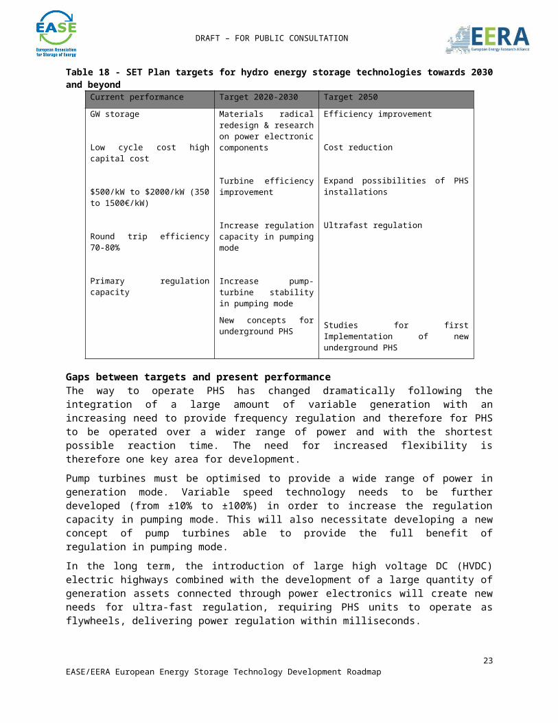
SET-Plan targetsTable 18 - SET Plan targets for hydro energy storage technologies towards 2030 and beyond
Current performance Target 2020-2030 Target 2050GW storage
Low cycle cost high capital cost
$500/kW to $2000/kW (350
Materials radical redesign & research on power electronic components
Turbine efficiency improvement
Efficiency improvement
Cost reduction
Expand possibilities of PHS
20EASE/EERA European Energy Storage Technology Development Roadmap

DRAFT – FOR PUBLIC CONSULTATION
to 1500€/kW)
Round trip efficiency 70-80%
Primary regulation capacity
Increase regulation capacity in pumping mode
Increase pump-turbine stability in pumping modeNew concepts for underground PHS
installations
Ultrafast regulation
Studies for first Implementation of new underground PHS
Gaps between targets and present performanceThe way to operate PHS has changed dramatically following the integration of a large amount of variable generation with an increasing need to provide frequency regulation and therefore for PHS to be operated over a wider range of power and with the shortest possible reaction time. The need for increased flexibility is therefore one key area for development.Pump turbines must be optimised to provide a wide range of power in generation mode. Variable speed technology needs to be further developed (from ±10% to ±100%) in order to increase the regulation capacity in pumping mode. This will also necessitate developing a new concept of pump turbines able to provide the full benefit of regulation in pumping mode.In the long term, the introduction of large high voltage DC (HVDC) electric highways combined with the development of a large quantity of generation assets connected through power electronics will create new needs for ultra-fast regulation, requiring PHS units to operate as flywheels, delivering power regulation within milliseconds.The other major gap between needs and present performance is to reduce the inherent limitation that is PHS’s dependence on geography. Equipping very high head (above ~700m) and very low head (below ~100m) sites remains challenging due to different problems: current multi-stage reversible pump-turbines (RPTs) used above 1000m head do not provide power regulation in generating mode; in low-head sites, the pump-turbine behaviour at part load is affected by too low efficiency in both modes and by unstable operating conditions in pumping mode.Therefore, very high head pumped storage power plants would require new, economically viable solutions to provide the much needed flexibility: technologies such as variable speed or multiple stages regulated RPT need further developments. This should foster developments for equipment for higher and lower head sites and for upgrading conventional hydro into PHP as well as for new energy storage plant concepts.
Research prioritiesSome of the main research priorities for PHS are the following:
1. Increasing PHS flexibility by: Developing a full range variable-speed motor generator (±100%) to allow
secondary regulation in pumping mode (suggested target for 2030) and,
21EASE/EERA European Energy Storage Technology Development Roadmap

DRAFT – FOR PUBLIC CONSULTATION
in the long term, to allow the PHS units to operate as flywheels and deliver power regulation in milliseconds (suggested target for 2050). Possible synergies between PHS technology and HVDC technology to develop large variable speed solutions with power electronics on the stator should be investigated;
Increasing the pump-turbine stability during transition between operating modes and at part loads in pumping mode in order to shorten start-up and transition times (from seconds to few minutes) and to favour the exploitation of low-head site. The development of new design criteria for pump-turbines will be necessary (suggested 2030 target).
2. Expanding possibilities for installation of PHS by: Developing pump-turbines allowing the upgrading of conventional hydro
power plants into PHS while keeping the existing powerhouses to minimise costs and environmental impacts. This will require a new pump-turbine design particularly focusing on the cavitation behaviour to overcome the problems related with the general need of lower foundations in pumping mode (2030 target);
Studying the development of PHS adopting the sea as a lower reservoir or underground cavern as a lower or, less often, upper reservoir (2050 target);
For various types of new underground PHS, the development of a standard geology based site selection scheme, including identification and evaluation processes for the different public and industrial stakeholders, is essential. It has to be coupled with a new specialised multi-modal safety operation monitoring concept (2030 target);
Expanding possibilities to equip more complex sites: going to very high head with the development of multiple stage solutions and very low head with other types of turbines (Deriaz or bulb). Particular application of a low head PHS to investigate will be the Energy Island concept with a reservoir in the sea (2050 target).
3. In a long-term perspective it will be extremely useful to support research on new PHS concepts (e.g. by moving solid mass like soil, gravity power, and bladder reservoir).
4. In order to increase turbine and pump-turbine lifetime, a better understanding of the fluid-structure interactions to limit vibrations coming from hydraulic “turbulences” will be required.
5. Developing standardised mini/micro cost-competitive PHP applications as well as hybrid PHS-wind/photovoltaic applications for centralised/decentralised solutions should be supported.
22EASE/EERA European Energy Storage Technology Development Roadmap
DRAFT – FOR PUBLIC CONSULTATION
Recommendations for research funding, infrastructure and incentivesThe following table shows the estimated R&D needs for the period towards 2030:Table 19 - Estimated R&D needs for hydro energy storage technologies
Field Subject Budget # projects
Flexibility
Full range variable-speed motor generator 3-10M€ 12Wider pump-turbine working range 3-10M€ 9
Improved ICT technology: Information, intelligent and interactive 2-10M€ 6
Geographic limitation reduction
More complex sites to equip 2-10M€ 11
Seawater and underground PHS 10M€ 6New plant and reservoir concepts 5-10M€ 8
Upgrade conventional Hydro into Pump Turbine 5-10M€ 5
For demonstration and pilot test projects it is estimated that each topic will require a budget in the range of up to several hundreds of millions Euros with a need for funding of about one third.
23EASE/EERA European Energy Storage Technology Development Roadmap