Energy Storage Modules (ESM) Up to 4 MW Output voltage ... · PDF fileEnergy Storage Modules...
20
Energy Storage Modules (ESM) Up to 4 MW Output voltage range of 120 volts to 40.5 kV
Transcript of Energy Storage Modules (ESM) Up to 4 MW Output voltage ... · PDF fileEnergy Storage Modules...

Energy Storage Modules (ESM)Up to 4 MWOutput voltage range of 120 volts to 40.5 kV

2 ESM Energy Storage Modules | Descriptive bulletin
Table of contents
Definition ................................................................................................................................................................................. 3
Applications ............................................................................................................................................................................. 4
Features ................................................................................................................................................................................... 6
Components ............................................................................................................................................................................ 7
Technical data sheet - ESM pre-designed modules .............................................................................................................. 12
Typical sketch - ESM pre-designed unit ............................................................................................................................... 14
Technical data sheet - CEM pre-designed units .................................................................................................................... 15
Summary ................................................................................................................................................................................ 16
Notes ..................................................................................................................................................................................... 18

Descriptive bulletin | ESM Energy Storage Modules 3
An Energy Storage Module (ESM) is a packaged solution that
stores energy for use at a later time. The energy is usually
stored in batteries for specific energy demands or to effectively
optimize cost.
ESM can store electrical energy and supply it to designated
loads as a primary or supplementary source. Moreover, it pro-
vides a stable and continuous power supply regardless of the
supply source status. Voltage and frequency regulation can also
be improved by using ESM modules.
ESM contains inverters that rectify the AC energy into DC to
store in the batteries and then invert the DC energy into AC
energy. The energy inverted into AC power can be connected
to the electrical network at low (<1000 Volts) or medium voltage
(<40.5 kV).
ABB provides the necessary electrical, protective and moni-
toring equipment along with the battery system to utilize the
batteries safely with a pre-designed system designed to meet
ANSI, IEC, and other international standards. This will guarantee
a high level of energy continuity and superior power quality in a
safe and cost effective module.
ESM is available in several capacities with individual modules up
to 4 MW and an output voltage range from 120 volts to 40.5 kV
at 50 or 60 Hertz, single or three phase system.
The ESM enclosure is engineered to maintain the internal
temperature within the design limits as well as provide protec-
tion. Different temperature classes and protection degrees are
available according to the application and size. The degree of
protection for the ESM enclosure is designed according to IP or
NEMA standards.
Definition

4 ESM Energy Storage Modules | Descriptive bulletin
ESM has different applications within the distribution network
aiming to improve the quality and continuity of the power at
optimal cost. The main applications of the ESM are:
Load shifting / time of use management: The practice of
altering the pattern of energy use so that on-peak energy use is
shifted to off-peak periods.
Benefits:
a) Reduces the cost of energy by charging the system with low
priced energy and discharging later when the energy prices are
high
b) Shifts renewable generation to peak times, allowing for
participation in capacity markets as a dispatchable resource,
smoothing the renewable output
Peak shaving: Peak shaving is related to Load Shifting. Both
are part of the demand management in which the ultimate goal
is to increase the load factor.
Benefits:
a) Commercial and industrial customers reduce their energy
charges by improving their load factor
b) Utilities reduce the operational cost of generating power dur-
ing peak periods (reducing the need for peaking units)
c) Investment in infrastructure is delayed because they have flat-
ter loads with smaller peaks.
Graph number 1 below shows a peak shaving/load shifting
application. The blue line shows the customer demand profile,
which is peaking late in the afternoon. The purple line shows
what the Energy Storage Module is doing, charging early in
the morning when the demand is low and discharging when
the demand is peaking. The yellow line shows the net effect on
the electrical grid (a lower demand peak and a more balanced
demand).
Renewable energy smoothing or ramp control: Reduces the
impact of quick changes in renewable generation levels. It can
be used to ensure that wind-farm ramp-rates (MW/min) are kept
within design limits and to eliminate rapid voltage and power
swings on the electrical grid.
Graph number 2 on the next page shows a renewable smooth-
ing ramp control application. The wind farm power is shown in
orange. The ESM system power is shown in blue. The black line
shows the net effect on the electrical grid (a gentler ramp slope
and lower variability).
Renewable capacity firming: Helps maintain the power output
at a committed (firm) level for a period of time.
Applications
-400
-200
0
200
400
600
800
1000
0:00 4:00 7:38 11:15 15:15 19:15 23:15
Time of day [hr]
Pow
er [k
W]
Customer Demand profile [kW]Battery charging/discharging Power [kW]Resultant Grid Demand Profile [kW]
Graph 1: Peak shaving/load shifting

Descriptive bulletin | ESM Energy Storage Modules 5
Frequency regulation: In this application, the ESM charges
and discharges in response to analog signals received every 1
to 4 seconds. The system supports the frequency on the grid
and keeps a state-of-charge of approximately 50%. ESM is an
attractive option for this application due to its rapid response
time.
Spinning reserves: In this application, the ESM remains
charged and responds in case of a generation or transmission
outages. Depending on the application need, the system can re-
spond within milliseconds or minutes. The ESM supplies power
until the back-up generator is started and running.
This application allows the generators to work at optimum pow-
er, without the need to keep idle capacity for spinning reserves.
The system can also eliminate the need of having back-up
generators running idle.
Outage management: ESM can provide power for short peri-
ods of time to a network reducing or eliminating the effect of a
temporary outage.
Delay in line upgrades: An ESM can be placed electrically
downstream in a congested transmission system, helping to
reduce the overloads in the lines and delay investments in line
upgrades.
Power quality: An ESM helps protect the loads further down-
stream against short-duration events that affect the quality of
power delivered to the load.
Voltage and VAR support: An ESM can help to maintain the
grid voltage by injecting or absorbing reactive power (VAR)
Railroad applications: Accelerating a heavy train can expose
the grid to a peak load that traditionally necessitated extensive
investment in capacity expansion. An ESM unit can supply the
required acceleration power that is taken from the most recent
deceleration.
Graph 2: Renewable energy smoothing or ramp control

6 ESM Energy Storage Modules | Descriptive bulletin
− High level of reliability and power supply continuity
− High level of safety for equipment and personnel
− Simple and quick installation
− High quality galvanized steel sandwich type housing
solutions
− Concrete substations available upon request
− Upon request, certain ESM modules can be designed with
arc proof design (according to IEC standard 62271-202)
− Modules with a power rating of up to 4MW
− For power requirements higher than 4 MW, several ESM
modules can be connected in parallel and be controlled as a
single unit
− Output voltage range of 120 volts to 40.5 KV at 50 or 60
Hertz, single or three phases system
− Dry type transformers to reduce maintenance costs and risk
− Oil type transformer also available
− Upon-request battery racks designs to maximize cooling and
efficiency
− Compartmented and segregated enclosures available
− Standard ratings and enclosure sizes. Tailor made dimen-
sions are available upon request
− Safety interlocked designs available
− Engineered enclosure for efficient cooling in order to keep the
temperature of the equipment within the design limits
− SCADA ready packages available
− Optimal product selection for grid connection combining ABB
products and customer interface requirements
− Seamless integration of high quality products to assure high
reliability
− Proven track record of containerized solutions in many severe
environments all over the world
Features

Descriptive bulletin | ESM Energy Storage Modules 7
The ESM portfolio includes two types of ABB inverters, which
are selected depending on the application and the power of
the modules: ABB LV ESI inverter and ABB LV PCS inverter. A
description of these two platforms is included in the following
section.
Battery Management System (BMS)
The BMS will perform the measurement necessary to manage
the batteries (measuring variables like voltage, temperature, cur-
rent) in order to extend the battery life and increase the safety of
the system. The communication between the BMS and inverter
control system is pretested in order to achieve a safer and
quicker installation.
Batteries
ESM includes different types of preselected Lithium ion battery
technologies, selected by ABB’s in-house team of battery ex-
perts to ensure that they can perform according to the applica-
tion requirements. ABB can also design and supply customized
solutions with other battery technologies (Lead acid, Nickel
Cadmium, Sodium Nickel Chloride, among others).
Typical one line diagram for a three-phase system:
Inverter
Controller
BMS Unit
HMI
Customer Communication
Electrical Network
Step-Up XFMR
Inverter
Batteries
Vacuum Breaker
(Fuse Disconnector-Optional)
Low Voltage Contactor
Low Voltage Breaker
Components
ESM is an integrated system of power equipment such as
transformers, low and medium voltage switchgear together with
automation equipment such as inverters in a galvanized steel
enclosure. This unique design provides quick, simple installa-
tion, with a high level of safety for the equipment as well as for
operators or people around.
Low and medium voltage switchgear
The energy from batteries is connected to the network through
the medium or low voltage switchgear depending on the ap-
plication. The ABB switchgear guarantees state-of-the-art
protection for a safe and reliable performance of the ESM in the
electrical network. ESM can be provided with a SCADA pack-
age which facilitates the remote monitoring and control of the
switchgear and inverters.
Transformer
The transformer can be a dry or oil type per user requirements.
Several ratios, voltage, connections, and frequencies are avail-
able to meet network ratings.
Inverter
The inverter changes AC power to DC to charge the batteries
(if supplied as AC) and the DC energy from the batteries into
single or three phase AC energy at 50 or 60 Hertz depending on
the user requirements.
Network
ESM Medium or Low
Voltageswitchgear(optional)
Step up orisolation
transformer(optional)
Converter(DC:AC)
Batteries

8 ESM Energy Storage Modules | Descriptive bulletin
Components - ESM ABB invertersABB/LV ESI inverters for energy storage applications
Experienced and reliable inverter technology
ABB is a world leader in inverter technology. The ESM
portfolio includes two types of ABB inverters, which are
selected depending on the application and the power of the
modules.
Flexible, modular and redundant
ESI inverter is a modular design. Up to 32 inverters can be
connected together which provides a wide range of power.
Furthermore redundancy functionality permits compliance with
even the most stringent requirements on redundancy imposed
in critical applications.
Power quality
ABB ESI inverter propose unsurpassed functionality in term of
power quality such as:
− Reactive power compensation of both inductive and
capacitive loads
− Unprecedented harmonic filtering efficiency
− Load balancing in both 3 and 4-wire systems
Features
− Allows a range of energy storage devices to be coupled
to the grids
− Dynamic power control (P)
− Dynamic reactive power control (Q)
− Harmonic mitigation
− Islanding mode
− CAN communication
Model ESI-I ESI-M ESI-S
Ratings
Inverter maximum power at 415VAC
(3-phase) Up to 323kw in one unit Up to 108kw in one unit Up to 72kw in one unit
Battery voltage range V1: 600-830VDC
at 415VAC
V2: 975-1200VDC
at 690VAC
600-830VDC
at 415VAC
600-830VDC
at 415VAC
(3-phase)
170-830VDC
at 120VAC
(single-phase)
Electrical characteristics
Connection method 3-phase 3-phase 3-phase/3-phase + N/single-phase
AC Nominal Network voltage V1: 208-480VAC
V2: 480-690VAC
V1: 208-480VAC
208-240VAC
(3-phase)
380-415VAC
(3-phase)
120-415VAC
(single-phase)
Network frequency 50 Hz/60 Hz - +/- 5%
AC Line current per inverter(Arms
) V1: 300 A, 450 A
V2: 180 A, 320 A
70 A, 100 A, 130 A, 150 A 30 A, 45 A, 60 A, 70 A, 80 A, 90 A,
100 A
Neutral current rating per inverter (Arms
) - - 3 times the line current rating(1)
Modularity Maximum 32 inverters can be combined
Redundancy(2) Master/master or master/slave arrangement
Equipment losses 3% of the equipment rated power typically

Descriptive bulletin | ESM Energy Storage Modules 9
ComponentsABB/LV ESI inverters for energy storage applications
Model ESI-I ESI-M ESI-S
Internal power circuit protection Circuit breaker Fuse box disconnector (optional) -
Power quality characteristics
Reactive power compensation: target cos Φ Programmable from 0.6 (inductive) to 0.6 (capacitive)(3)
Harmonic mitigation
Harmonic range Up to 2nd to 50th harmonic(4)
Harmonics selectable 20 individual harmonics 3-wire: 20 harmonics
4-wire: 15 harmonics
Filtering target Programmable for each harmonic in absolute Ampere value
Harmonic attenuation factor
(IH (source)/I
H (load))
Better than 97% at rated load
Reaction time < 500μs instantaneous response
Response time 2 networks cycles typically (10-90% filtering)
Load balancing characteristics Balance the currents between phases and/or between phases and neutral
Programming/communication
Digital I/O 2 digital inputs/6 digital outputs (potential free)
Alarm contact 1 NO/NC alarm contact (potential free)
Programming/Monitoring Using PQF-Manager GUI
Using Modbus RTU interface (optional)
Using PQF-Link software (optional)
Battery Management System communication CAN
Mounting Free floor standing cubicle (ESI-I-M) or IP00 plate (ESI-M) Wall-mount enclosure
Dimensions per inverter
(W x D x H)
800 x 600 x 2150 mm 600 x 600 x 2150 mm (cubicle) 585 x 310 x 700 mm
498 x 432 x 1697 mm (plate)
Approximate weight (unpacked) 180 A/250 A units: 525 kg
320 A/450 A units: 620 kg
270 kg (cubicle)
150 kg (plate)
120 kg
Color RAL 7035 (light gray)
IP protection IP21
Optional: IP41(5)
Plate version: IP00
Cubicle version: IP21
Optional: IP41(5)
IP30
Installation aspects
Altitude Indoor installation in clean environment up to 1000 m altitude(6)
Ambient temperature -10°C to 40°C(6)
Humidity Maximum 95% relative humidity, non-condensing(7)
Cable entry Bottom Top or bottom (to be specified at
time of ordering)
Bottom
CT requirements Only required for Power Quality features
Standards
UL UL-508 -
IEC 60439-1 (EMC class)
EMC Immunity: 61000-6-2
EMC Emissions: 61000-6-4(1) Neutral current rating of PQFS 100 A units is limited to 270 A
rms.
(2) For full redundancy combine only master units. If limited redundancy is acceptable, master and slave units can be combined. The desired redundancy level can be obtained by
selecting more or less master units.(3) If cos Φ of the installation is higher than the target cos Φ, the fi lter will not downgrade the existing cos Φ(4) ESI inverter cannot fi lter zero sequence if it does not have a neutral connection.(5) For IP41 models, 10% derating applies. (6) Higher altitudes (up to 2000 m/ 6600 ft max.) and temperatures (up to 50°C/122°F max.) with suitable derating.(7) The maximum relative humidity for operational purposes is 95%. When the units are stored for a longer time, do not exceed a relative humidity of 85%.

10 ESM Energy Storage Modules | Descriptive bulletin
Components - ESM ABB convertersABB/LV PCS inverters for energy storage applications
Experienced and reliable inverter technology
ABB is a world leader in inverter technology. The ESM portfolio
includes two types of ABB inverters, which are selected de-
pending on the application and the power of the modules.
Features
– Allows energy storage devices to be coupled to the grid
– Dynamic power control (P)
– Dynamic reactive power control (Q)
– Current source mode for sub-cycle response to power commands
– Virtual Generator Control Mode providing grid stabilization via
synthetic inertia and active damping
– High and low voltage ride through
– Modular inverter blocks for simple long term maintenance
– Scalable building block design
– Redundant inverter design increases reliability and availability
Options
– Island mode
– Black start capability
– Dynamic control for applications such as peak-shaving, spinning
reserve, etc.
The ABB Power Conversion System is designed to be a complete
package including everything between the battery and the utility bus.
Main components of the PCS
– AC circuit breakers and protection
– Main isolation/step-up transformer
– Auxiliary transformer and power distribution circuit
– Sine wave fi lter network
– Inverters
– DC circuit breakers and protection
– Local and remote control
Descriptive bulletin | ESM Energy Storage Modules 11
Components - ESM ABB convertersABB/LV PCS inverters for energy storage applications
A - PCS temperature rating depends on housing selection; PCS100 interverters are derated over 40°C B - Systems derated above 1000 mC - Indoor 500 kW cabinet solution control cabinet mounted in cabinet if space permits, otherwise separate mounting
Configurations 500 kW cabinet 1000 kW rack
Protection class NEMA 1, 3R & 4 NEMA 1, 3R & 4
Unit continous kW rating 70-500 300-700 650-1300
MVAr System applied All configurations can be paralleled to obtain higher ratings needed
DC system
DC voltage range (VDC) 400-1120 400-1120
Voltage ripple IEEE compliant IEEE compliant
AC grid
AC grid voltage (kV) .2 to 35 .2 to 35
AC tolerance +/-10% +/-10%
Output Frequency 50 / 60 50 / 60
Harmonic Distortion, Current IEEE compliant IEEE compliant
Efficiency
PCS efficiency >94% >94%
PCS100 inverter efficiency >97% >97%
Environmental limits
Cooling Forced Air Forced Air
Ambient temperature range (nominal) A 0°C to 50°C 0°C to 50°C
Relative humidity 0 to 100% 0 to 100%
Maximum altitude ft (m)B 9843 (3000) 9843 (3000)
Seismic rating Zone 4 Zone 4
Noise level of inverters 75-85 dBA 75-85 dBA
Housing options - dimensions and weights
A) Indoor package, in (mm) 0°C to 50°C A,C 32Wx32Dx85H
(809x804x2154)
88Wx32Dx97H
(2241x800x2464)
128Wx32Dx97H
(3241x800x2464)

12 ESM Energy Storage Modules | Descriptive bulletin
Technical data sheet - Pre-designed modules
Storage
Energy Size
(kW / kWh)
Typical
Application Phases
Output
Voltage
Type of Enclosure /
Approximate Dimension Cycle life Components
25 / 50
Outage management/
Time of use manage-
ment/Peak Shaving/
Capacity Firming
1 or 3 Up to
690 V
Two Enclosures
a) Connection equipment
(one):
W=3’11”/1185 mm
D=2’4”/710 mm
H=5’8”/1710 mm
b) Battery Enclosure (one):
W=5’8”/1715 mm
D=5’4”/1610 mm
H=4’10”/1470 mm
1000 cycles at rated power
and energy
Battery rack, Battery Manage-
ment system, DC protection,
Inverter, AC protection, control
system
500 / 125
Outage management/
Capacity Firming/Fre-
quency regulation
3 Up to
690 V
W=26’9”/8141 mm
D=8’3”/2513 mm
H=8’4”/2539 mm
The system will charge or
discharge, per 5 years, in
response to a frequency
regulation signal received
every 4 seconds
Battery rack, Battery Manage-
ment system, DC protection,
Inverter, AC protection, control
system
Note: The scope does not in-
clude an Isolation transformer
500 / 1500
Outage management/
Time of use manage-
ment/Peak Shaving/
Capacity Firming/Fre-
quency regulation
3
Up to
690 V or
Medium
Voltage up
to 24 kV
Three Enclosures:
a) Connection equipment
(one):
W=15’11”/4830 mm
D=8’3”/2515 mm
H=8’4”/2539 mm
b) Battery Enclosure (two):
W=40’/12192 mm
D=8’/2438 mm
H=8’6”/2591 mm
2000 cycles at rated power
and energy
Battery rack, Battery Manage-
ment system, DC protection,
Inverter, AC protection, control
system
Note: The scope does not in-
clude an Isolation transformer
1000 / 250
Outage management/
Capacity Firming/Fre-
quency regulation
3
Up to
690 V or
Medium
Voltage up
to 24 kV
W= 49’ 3”/ 15000 mm
D= 8’3” / 2513 mm
H= 8’4” / 2539 mm
The system will charge or
discharge, per 5 years, in
response to a frequency
regulation signal received
every 4 seconds
Battery rack, Battery Manage-
ment system, DC protection,
Inverter, AC protection, control
system, Step-up Transformer,
MV Switchgear
An Energy Storage Module (ESM) is a packaged solution
that stores energy for use at a later time. The energy is
usually stored in batteries for specific energy demands or
to effectively optimize cost. The Energy Storage Modules
include all the components required to store the energy and
connect it with the electrical grid.

Descriptive bulletin | ESM Energy Storage Modules 13
All information subject to change without notifi cation.
Scope and dimensions may vary depending on the application.
For connection voltages higher than 24 kV, a customized solution can be supplied.
For power requirements higher than 4 MW, several ESM modules can be connected in parallel and be controlled as a single unit
Storage
Energy Size
(kW / kWh)
Typical
Application Phases
Output
Voltage
Type of Enclosure /
Approximate Dimension Cycle life Components
1000 / 3000
Outage management/
Time of use manage-
ment/Peak Shaving/
Capacity Firming/Fre-
quency regulation
3
Up to
690 V or
Medium
Voltage up
to 24 kV
Four Enclosures:
a) Connection Equipment
one):
W= 22’ 5”/ 6830 mm
D= 8’3” / 2515 mm
H= 8’4” / 2539 mm
b) Battery Enclosure (three):
W= 43’ 12” / 13400 mm
D= 8’3” / 2513 mm
H= 8’4” / 2539 mm
2000 cycles at rated power
and energy
Battery rack, Battery Manage-
ment system, DC protection,
Inverter, AC protection, control
system, Step-up Transformer,
MV Switchgear
2000 / 500
Outage management/
Capacity Firming/Fre-
quency regulation
3
Up to
690 V or
Medium
Voltage up
to 24 kV
Three Enclosures:
a) Connection equipment
(one):
W=20’/6096 mm
D=8’/2438 mm
H=8’6”/2591 mm
b) Battery Enclosure (two):
W=40’/12192 mm
D=8’/2438 mm
H=8’6”/2591 mm
The system will charge or
discharge, per 5 years, in
response to a frequency
regulation signal received
every 4 seconds
Battery rack, Battery Manage-
ment system, DC protection,
Inverter, AC protection, control
system, Step-up Transformer
2000 / 6000
Outage management/
Time of use manage-
ment/Peak Shaving/
Capacity Firming/Fre-
quency regulation
3
Up to
690 V or
Medium
Voltage up
to 24 kV
Seven Enclosures:
a) Connection equipment
(one):
W=20’/6096 mm
D=8’/2438 mm
H=8’6”/2591 mm
b) Battery Enclosure (six):
W=43’12”/13400 mm
D=8’3”/2591 mm
H=8’4”/2539 mm
2000 cycles at rated power
and energy
Battery rack, Battery Manage-
ment system, DC protection,
Inverter, AC protection, control
system, Step-up Transformer
4000 / 1000
Outage management/
Capacity Firming/Fre-
quency regulation
3
Up to
690 V or
Medium
Voltage up
to 24 kV
Three Enclosures:
a) Connection equipment
(one):
W=40’/12192 mm
D=8’/2438 mm
H=8’6”/2591 mm”
b) Battery Enclosure (two):
W=40’/12192 mm
D=8’/2438 mm
H=8’6”/2591 mm
The system will charge or
discharge, per 5 years, in
response to a frequency
regulation signal received
every 4 seconds
Battery rack, Battery Manage-
ment system, DC protection,
Inverter, AC protection, control
system, Step-up Transformer

14 ESM Energy Storage Modules | Descriptive bulletin
Typical sketch - Pre-designed unitEnergy Storage Module for 1000 kW/250 kWh
Applications Capacity Firming
Voltage Support
Frequency regulation
Dimensions with Connection equipment (Transformer, MV switchgear),
as showed in the sketch
W= 49’ 3”/ 15000 mm
D= 8’3” / 2513 mm
H= 8’4” / 2539 mm
Total Number of Enclosures 1
Output Voltage 15 KV
3 Phases
60 Hertz
Components Battery rack
Battery Management System
DC protection
Inverter
AC protection
Control system
Step up transformer
Medium Voltage (MV) Switchgear
Enclosure Type Outdoor
All information subject to change without notifi cation.
MV Switchgear
Transformer
Inverter
Battery
Descriptive bulletin | ESM Energy Storage Modules 15
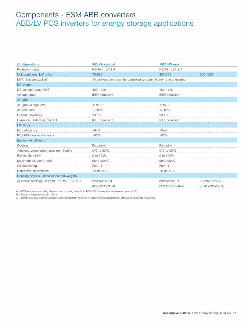
Storage
Energy Size
(kW)
Phases Output Voltage
Type of Enclosure /
Approximate Dimension Components
1000 3
Up to 690 V or
Medium Voltage
up to 24 kV
W= 22’ 5”/ 6830 mm
D= 8’3” / 2515 mm
H= 8’6” / 2591 mm
DC protection, Inverter, AC protection, control
system, Step/up- Isolating transformer, MV
switchgear
1000 3
Up to 690 V or
Medium Voltage
up to 24 kV
W= 20’ / 6096 mm
D= 8’ / 2438 mm
H= 8’6” / 2591 mm
DC protection, Inverter, AC protection, control
system, Step/up- Isolating transformer.
Note: MV switchgear is not included
2000 3
Up to 690 V or
Medium Voltage
up to 24 kV
W= 20’ / 6096 mm
D= 8’ / 2438 mm
H= 8’6” / 2591 mm
DC protection, Inverter, AC protection, control
system, Step/up- Isolating transformer.
Note: MV switchgear is not included
4000 3
Up to 690 V or
Medium Voltage
up to 24 kV
W= 40’ / 12192 mm
D= 8’ / 2438 mm
H= 8’6” / 2591 mm
DC protection, Inverter, AC protection, control
system, Step/up- Isolating transformer.
Note: MV switchgear is not included
A Connection Equipment Module (CEM) unit is a packaged
solution that includes all the components required to connect a
battery system with the AC grid (Inverter, transformer, protection
equipment, control system, etc.)
Technical data sheet - Pre-designed connection equipment Modules (CEM)
Connection Equipment Module for 1000 kW
MV Switchgear
Transformer
Inverter
All information subject to change without notifi cation.
Scope and dimensions may vary depending on the application.
For connection voltages higher than 24 kV, a customized solution can be supplied.

16 ESM Energy Storage Modules | Descriptive bulletin
Summary
Soaring energy prices and concerns about climate change from
man-made emissions of carbon dioxide have propelled energy
efficiency to the top of the agenda in the boardroom, in public
debate and in public policy. Under this scenario, Energy Storage
Modules are a state-of-the-art technology which contributes to
raise the efficiency at every stage of the energy chain by:
− Increasing the capacity factor of generation, transmission and
distributions assets
− Improving the uniformity and efficiency with which electrical
energy is being used
− Raising Power Quality with better voltage and frequency
regulation as well as minimum interruptions
− Increasing the capacity factor of renewable energy sources in
order to make clean energy available for longer periods
− Providing a reliable source of energy to communities
An ESM module integrates batteries, transformers, and medium
and low voltage switchgear together with automation equipment
such as inverters in a galvanized steel enclosure. Completely
compartmented and segregated enclosures are available upon
request.
The modules are carefully engineered and tested, including the
enclosure, assuring high and safe performance.
ESM is the energy storage alternative for efficient and smart
electrical network operation through:
− Individual modules up to 4 MW
− Output voltage range of 120 volts to 40.5 kV at 50 or 60
Hertz, single or three phase system
− Enclosure designs with different temperature classes and
protection degrees according to the application and size
− Different types of batteries according to the application and
size
− Optimal product selection for grid connection combining ABB
products and customer interface requirements
− Seamless integration of high quality products to assure high
reliability
− Proven track record of containerized solutions in many severe
environments all over the world
− ABB’s vast and global experience in designing Modular
Systems, integrating electrical equipment in enclosures for
renewable, industrial and Utilities applications
− Global service coverage with a high level of engineering
capabilities
Descriptive bulletin | ESM Energy Storage Modules 17

18 ESM Energy Storage Modules | Descriptive bulletin
Notes

Descriptive bulletin | ESM Energy Storage Modules 19
Notes
Contact us
PP
MV
_P
G3
43
5_D
B_0
0 R
ev
E A
pril 2
01
2ABB Inc.
North America
655 Century Point
Lake Mary, Florida 32746
USA
Phone: +1 407 732 2000
ABB AS
Europe
Vana-Narva mnt 30/1
Maardu, Estonia
Phone: +372 6349 295
ABB Inc.
Asia
Oksan Bldg. 7th Fl.
157-33, Samsung-dong, Gangnam-ku, Seoul
South Korea
Phone: +82 2-528-2369
www.abb.com/mediumvoltage
We have factories located all over the world to support
your needs. For more information please contact the
Modular Systems Product Group of North America, Asia,
or Europe.
All sales are subject to ABB General Terms and Condi-
tions of Sale.
While every effort has been made to assure accuracy, the
information in this document is subject to change without
notice.
© Copyright 2010, 2012 ABB Inc. All rights reserved.