Energy Solutions - · PDF fileIn October 2014, Hitachi, Ltd. established its Energy Solutions...
11
59 2015 64-03 Hitachi Review Power Systems Energy Solutions Trends in the Energy Solutions Business 1 e business environment surrounding the world’s electricity markets has been changing dramatically in recent years, with growing awareness of environmental problems, the development of alternative energy sources such as shale gas, increasing urban- ization, and an expansion in demand for power generation capacity in emerging markets that is set against the aging of infra- structure in developed economies. is background has set the scene for debate on a shiſt from existing centralized power plants and large distribution networks operated by vertically integrated regional monopolies toward distributed generation, smart grids, and the entry of new operators made possible by progress on electricity system reform. Including Japan’s electricity market, these changes in the business environment affect on the energy value chain from upstream to downstream. Since the new value chain is character- ized by many more stakeholders than in the past, it is expected to deliver the following new business opportunities. (1) Businesses made possible by energy market liberalization ere has been ongoing debate over electricity system reform, including the separation of generation and transmission, that seek to reduce electric power charges by introducing competition. It is anticipated that energy market liberalization will increasingly see participants from outside the industry joined in the new elec- tricity business including existing power companies. Hitachi plans to provide end-to-end supports from the procurement of power resource to the general works needed for power producer and supplier (PPS) operators. (2) Renewable energy (RE) and other distributed energy resource (DER) businesses Energy security considerations are recognized as prompting growth in demand for locally-produced and locally-consumed business model in place of large centralized power plants. In addition, from the viewpoint of reducing the CO2 emissions, photovoltaic, wind, and other forms of renewable energy will be also increasingly spreading. (3) Businesses that combine information technology (IT) and operation and maintenance (O&M) with existing products Along with its existing business of supplying equipment in accordance with customer specifications, Hitachi sees the potential solutions that include the use of big data for predictive diagnosis systems and maintenance, and the outsourcing of power plant operations. e secret to the development of the solution business lies in a three-way strategy of differentiating from competitors by offering distinctive solutions, by categorizing expected market size, and by operating the business based on a global perspective. While the solutions that are too distinctive will compromise the market size by restricting them to a limited number of customers, it is difficult to differentiate from competitors when aiming for too wide of a market. In this respect, the keys to the success of the solution business are an ability to think in global terms from the outset, and the establishment of a business development organization that can work rapidly through the cycle of testing and discarding numerous potential business models. In October 2014, Hitachi, Ltd. established its Energy Solutions Division as a “front engineering” (technical sales) organization, under the direct jurisdiction of the President, providing optimum solutions to energy and power system markets that are being reformed in Japan and throughout the world in a one-stop format that extends from power generation to power transmission and distribution and end-user systems. By consolidating engineering divisions from across Hitachi that are involved in the energy solutions, distribution, and renewable energy businesses, the new division will establish the infrastructure for the timely supply of one-stop solutions tailored to the needs of power companies and other stakeholders in the energy and power system markets. Energy Solutions Existing energy value chain Fuel supply Generation Transmission Distribution Retail Fuel supply Generation Transmission Distribution Retail Consumers Consumers Liberalization Continued regulation Existing power companies Liberalization New energy value chain Power companies (fuel, generation), gas companies, oil companies, new forms of electric power, IPP, trading companies Power companies (distribution), organization for nationwide coordination of transmission operators Power companies (retail), new forms of electric power, IT & telecommunication companies Reforms to energy value chain in the Japanese electricity market 1 IPP: independent power producer
Transcript of Energy Solutions - · PDF fileIn October 2014, Hitachi, Ltd. established its Energy Solutions...

592015 64-03Hitachi Review
Pow
er Systems
Energy Solutions
Trends in the Energy Solutions Business1Th e business environment surrounding the world’s electricity markets has been changing dramatically in recent years, with growing awareness of environmental problems, the development of alternative energy sources such as shale gas, increasing urban-ization, and an expansion in demand for power generation capacity in emerging markets that is set against the aging of infra-structure in developed economies. Th is background has set the scene for debate on a shift from existing centralized power plants and large distribution networks operated by vertically integrated regional monopolies toward distributed generation, smart grids, and the entry of new operators made possible by progress on electricity system reform.
Including Japan’s electricity market, these changes in the business environment aff ect on the energy value chain from upstream to downstream. Since the new value chain is character-ized by many more stakeholders than in the past, it is expected to deliver the following new business opportunities.(1) Businesses made possible by energy market liberalization
Th ere has been ongoing debate over electricity system reform, including the separation of generation and transmission, that seek to reduce electric power charges by introducing competition. It is anticipated that energy market liberalization will increasingly see participants from outside the industry joined in the new elec-tricity business including existing power companies. Hitachi plans to provide end-to-end supports from the procurement of power resource to the general works needed for power producer and supplier (PPS) operators.(2) Renewable energy (RE) and other distributed energy resource (DER) businesses
Energy security considerations are recognized as prompting growth in demand for locally-produced and locally-consumed business model in place of large centralized power plants. In
addition, from the viewpoint of reducing the CO2 emissions, photovoltaic, wind, and other forms of renewable energy will be also increasingly spreading.(3) Businesses that combine information technology (IT) and operation and maintenance (O&M) with existing products
Along with its existing business of supplying equipment in accordance with customer specifi cations, Hitachi sees the potential solutions that include the use of big data for predictive diagnosis systems and maintenance, and the outsourcing of power plant operations.
Th e secret to the development of the solution business lies in a three-way strategy of diff erentiating from competitors by off ering distinctive solutions, by categorizing expected market size, and by operating the business based on a global perspective. While the solutions that are too distinctive will compromise the market size by restricting them to a limited number of customers, it is diffi cult to diff erentiate from competitors when aiming for too wide of a market. In this respect, the keys to the success of the solution business are an ability to think in global terms from the outset, and the establishment of a business development organization that can work rapidly through the cycle of testing and discarding numerous potential business models.
In October 2014, Hitachi, Ltd. established its Energy Solutions Division as a “front engineering” (technical sales) organization, under the direct jurisdiction of the President, providing optimum solutions to energy and power system markets that are being reformed in Japan and throughout the world in a one-stop format that extends from power generation to power transmission and distribution and end-user systems. By consolidating engineering divisions from across Hitachi that are involved in the energy solutions, distribution, and renewable energy businesses, the new division will establish the infrastructure for the timely supply of one-stop solutions tailored to the needs of power companies and other stakeholders in the energy and power system markets.
Energy Solutions
Existing energy value chain
Fuel supply Generation Transmission Distribution Retail
Fuel supply Generation Transmission Distribution Retail Consumers
Consumers
LiberalizationContinued regulation
Existing power companies
Liberalization
New energy value chain
Power companies (fuel, generation), gas companies, oil companies, new forms of electric power, IPP, trading companies
Power companies (distribution), organization for nationwide coordination of transmission operators
Power companies (retail), new forms of electric power, IT & telecommunication companies
Reforms to energy value chain in the Japanese electricity market1
IPP: independent power producer

60 Power Systems
Power G
eneration Equip
ment and
Systems
Pow
er Systems
New 42-MW Pump-turbine Runners Commence Operation at Lewiston Pump-Generating Plant of New York Power Authority
1An upgrade to the fi rst 42-MW pump-turbine was completed at the New York Power Authority’s (NYPA) Lewiston Pump-Generating Plant, located downstream of Niagara Falls, and commenced commercial operation in September 2013. Th e plant features a maximum head of 36.6 m, which is very low for a pumped-storage hydro power plant. At the same time, the head range is about 18 m, which is large in proportion to the 36.6-m maximum head for these pump turbines.
Th e project to improve the characteristics of the existing pump-turbines, which were supplied by a diff erent manufacturer and entered service in 1961, included runner replacement, changes to the shapes of the guide vanes and stay vanes, and refurbishment of the embedded components. Th ese improved effi ciency by about 2 to 5% in turbine mode, depending on the head, and increased turbine output by 8 to 20%, again depending on the head. Pump effi ciency was also increased. Th e replacement runners have an outer diameter of 5.3 m. To ensure that the new runners would deliver a high level of hydrodynamic performance, Hitachi used stainless steel castings produced in Europe. Th e assembly; welding of the crown, band, and blades; and the machining and balancing were performed at Hitachi Works. Operational testing at the Lewiston plant confi rmed the unit can operate reliably across the entire operating range, in accordance with the model test.
Refurbishment has also been completed on the second unit, which commenced commercial operation in May 2014, with
on-site work on the third unit currently underway. Th e plant has 12 pump-turbines, with refurbishment of all units expected to be completed in 2020.(Hitachi Mitsubishi Hydro Corporation)
20.6-MW Kaplan Turbines and Generators for Cheongpyeong Hydro Power Plant Units 1 and 2 of Korea Hydro & Nuclear Power Co., Ltd. Commence Operation after Major Overhaul
2A major overhaul of Unit 1 and Unit 2 was undertaken at the Cheongpyeong Hydro Power Plant of Korea Hydro & Nuclear Power Co., Ltd., with Unit 1 recommencing commercial operation in May 2014 and Unit 2 in June of the same year.
Th e vertical-shaft Kaplan turbines and generators at the plant fi rst entered service in 1943, with an upgrade to the turbine runners and the stator coils and cores of the generators being undertaken in 1993. Th e latest overhaul consisted mainly of repairs (machining) to the fl ow surfaces of the turbines and upgrades to the stainless steel guide vanes, as well as to the generator rotor, governor, exciter, unit control panels, and other electrical equipment.
Th e main features resulting from the upgrade are listed below.(1) Improved turbine effi ciency as a result of repairing the turbine fl ow surfaces and upgrading the stainless steel guide vanes(2) Elimination of harm to the environment due to oil leaks as a result of adopting water bosses and water-lubricated bearings for the turbines(3) Adoption of environmentally conscious digital governor that is compliant with the Restriction of Hazardous Substances (RoHS)
Power Generation Equipment and Systems
Overview of NYPA’s Niagara Power Project (Lewiston is the power plant at the top) (left) and new pump-turbine runner under assembly (right)1

612015 64-03Hitachi Review
Pow
er Systems
Power G
eneration Equip
ment and
Systems
(standard Hitachi Mitsubishi Hydro Corporation product)(4) Better bearing reliability and lower losses as a result of using plastic bearings in generators
Hitachi Mitsubishi Hydro Corporation intends to continue supplying products for major overhauls of existing power plants, including features such as lower environmental risks and better maintenance and performance.(Hitachi Mitsubishi Hydro Corporation)
New Hydro Generation Equipment for Shuparo Power Plant of the Hokkaido Bureau of Prefectural Enterprises
3Th e installation of new hydro generation equipment at Unit 1 (24,800 kW) and Unit 2 (1,800 kW) of the Shuparo Power Plant of the Hokkaido Bureau of Prefectural Enterprises has been completed and commissioning has commenced with the aim of completing the project by March 2015.
Th is hydro power plant is located in Yubari, Hokkaido in Japan and is powered by water from the Yubari Shuparo Dam.
Th e main features of the hydro power plant are as follows.(1) Highly effi cient turbine runners designed using the latest tech-niques in computational fl uid dynamics(2) Air-cooled generator bearings that eliminate the need for cooling water supply(3) Water-lubricated turbine bearings that do not require lubri-cating oil (Unit 1)(4) Electrically operated guide vane, inlet valve and brake that eliminate the need for a hydraulic system
In the future, Hitachi Mitsubishi Hydro Corporation intends to
contribute to new hydro power plant projects and scrap-and-build projects at existing plants by making better use of renewable energy, reducing environmental risks such as oil leaks, and providing easier maintenance.(Hitachi Mitsubishi Hydro Corporation)
Replacement of Automatic Control System at Okumino Power Station of Chubu Electric Power Co., Inc.
4Th e automatic control system at the Okumino Power Station of Chubu Electric Power Co., Inc. has been in use since the plant entered commercial operation in 1994. Th is project will replace the 500-kV sequence controller, common sequence controller, Unit 1 and Unit 2 sequence controller, engineering workstation (EWS), and intelligent telecontroller (ITC).
Installation of controllers occurred in early October 2014 following integration testing of the complete system at the factory. On-site commissioning started in November 2014, with Unit 2 scheduled to commence commercial operation in March 2015 followed by Unit 1 in May 2015. Th e common control functions of Units 3 through 6 will be made operational coincident with replacing them.
Th e main characteristics of the project are as follows.(1) Th e plant’s local area network (LAN), which is currently
Cheongpyeong Hydro Power Plant Unit 1 (in the back) and Unit 2 (in the front) of Korea Hydro & Nuclear Power Co., Ltd. after completion of major overhaul
2
Unit 1 (top front) and Unit 2 (top back) of the Shuparo Power Plant of Hokkaido Bureau of Prefectural Enterprises, and Yubari Shuparo Dam and power plant (bottom)
3

62 Power Systems
Power G
eneration Equip
ment and
Systems
Pow
er Systems
based on existing star couplers, has been partly replaced with a 1,000-Mbit/s control network system to provide the data commu-nication with high-reliable and fast-speed between controllers (there is a long distance between each control room).(2) Monitoring and control of the 500-kV system have been changed from analog to digital, and an integrated monitoring and control system for transformation and generation has been created by designing on the same network with other sequence controllers.(3) Th e power system monitoring and control board have been changed from a mechanical board to an EWS with liquid crystal display (LCD), improved operation has been realized in terms of monitoring the power system, with an easy-to-use note-taking function for equipment shutdowns.(Hitachi Mitsubishi Hydro Corporation)
Exploratory Robots for Use in the Removal of Fuel from Fukushima Daiichi Nuclear Power Station
5Hitachi has developed two robots for use in the removal of fuel from Fukushima Daiichi Nuclear Power Station. Th e robots can conduct remote surveys over large areas, being able to change their shape and orientation to avoid obstacles, even in confi ned
spaces.Th e underwater swimming robot is used in the water-fi lled
reactor building to perform underwater surveys for identifying the location of leaks of the pooled water. A feature of this robot is its ability to travel both over dry land and through water, being
Star coupler
Intelligent telecontroller (dual system)
Control system
Control system
500-kVsequencecontroller
Common sequencecontroller Unit 1 sequence controller
Unit 1 sequence controllerUnit 1 to 4 commonsequence controller
500-kVcontrol panel
Operationalcontroller
Unit 5sequence
controller*
G/W
Underground control room (PP 2)
Underground control room (PP 2)
Underground control room (PP 1)
FDMDED
FDMDED
FDMDED
NCEC
FDMDED
NCEC
FDMDED
NCEC
Aboveground control room
Intelligenttelecontroller(dual system)
Aboveground control room
EWS
Electric power office
Central load dispatch office
Maintenancesupport
equipment*
Underground control room (PP 1)
Flat-panel display• View fault data and
measurements.• Used to set lock switches
Standalone control switch• Equipment control
can still function when there is a CPU shutdown or fault in host system.
G/W
Protection(LP, BP)Main
plant/protection panels
Main plant/protection panels
Inside power plant
Outside power plant
Outside power plant
Inside power plant
Protection (TP) Protection (G/M)
G/M
P/T
Protection (G/M)
G/M
P/T
LR
SFCCB, LS
Protection (LP, BP) Protection (TP)
Electric power office
Central load dispatch office
Protection (G/M)
G/M
P/T
LR
Optical ST
Unit 5 to 6 commonsequence controller*
Optical ST*
Unit 5sequence
controller*
Optical ST*Optical ST
Optical ST
Optical AD
SFC
Protection (TP)
LR
SFC
Protection (G/M)
G/M
P/T
CB, LS
Control network system
......
......
System confi guration of automatic control systems at Okumino Power Station of Chubu Electric Power Co., Inc. before (top) and after (bottom) replacement
4
AD: analog-to-digital, ST: station, LP: line protection, BP: bus protection, CB: circuit breaker, LS: line switch, TP: transformer protection, LR: load regulation, G/M: generator/motor, P/T: pump/turbine, G/W: gateway, CPU: central processing unit, NC: numerical control, EC: equipment control, FD: fault data, MD: measurement data, ED: equipment data, PP: power plant, SFC: static frequency converter* Supplied by other manufacturer
Underwater swimming robot
Shape-changing robot
Operation of underwater swimming robot
SwimmingHorizontal thruster Crawler
Vertical thrustersCable
Camera
Small crawlers
Changing orientation Traveling over wall
I-shaped configurationU-shaped configuration
Operation of shape-changing robot
Changing shape
Exploratory robots for use in the removal of fuel from Fukushima Daiichi Nuclear Power Station (top) and robot operation (bottom)
5

632015 64-03Hitachi Review
Pow
er Systems
Power G
eneration Equip
ment and
Systems
equipped with six thrusters (four vertical and two horizontal) and one set of crawlers. It entered use at the plant in July 2014.
Th e shape-changing robot, for use in highly radioactive envi-ronments, is able to enter the reactor containment vessel through a 100-mm diameter pipe and conduct extensive surveys. Th e robot consists of three articulated sections (the main body and two small crawlers) that form an I shape to pass through pipes and a U shape for travel over fl at ground. Th is combines stable movement with the ability to enter through narrow access ways. It is scheduled to enter use at the plant in April 2015.(Hitachi-GE Nuclear Energy, Ltd.)
Construction of New Nuclear Power Plants in Europe6
In August 2014, Hitachi-GE Nuclear Energy, Ltd. commenced stage three of the Generic Design Assessment (GDA) conducted by the UK Offi ce for Nuclear Regulation of the advanced boiling water reactors (ABWRs), which Horizon Nuclear Power Limited plans to build at Wylfa on the island of Anglesey and at Oldbury-on-Severn, South Gloucestershire. Th e GDA is progressing well and is scheduled to be completed by the end of 2017. Th e UK’s fi rst ABWR should commence generating electric power in the early 2020s.
With regard to the project to construct an ABWR at Visaginas in the Republic of Lithuania, meanwhile, following an agreement by all parties in the Lithuanian parliament to proceed with the project, Hitachi, Ltd. and the Lithuanian Ministry of Energy have agreed on a memorandum of understanding and are negotiating the establishment of an operating company. Th e Republic of Latvia and the Republic of Estonia also plan to participate in the project, which is scheduled to commence generation in the 2020s.(Hitachi-GE Nuclear Energy, Ltd.)
5.0-MW Wind Power Converter7Hitachi fi rst entered the Chinese market for wind power converters in 2008, having supplied 1.5-MW, 2.0-MW, 3.0-MW doubly fed (DF) models, and a 2.0-MW permanent magnet generator (PMG) model.*
In Japan, a 2.0-MW DF converter commenced fi eld tests in January 2014. Hitachi has now developed a 5.0-MW PMG converter for use with large off shore wind turbines.
Th e main features of these converters are as follows.(1) Water-cooled, direct-current (DC) 3.3-kV three-level inverter [capacity: 5,310 kVA (grid-side) and 5,460 kVA (generator-side), rated voltage: 1,800 V (grid-side) and 1,980 V (generator-side), and rated generator frequency: 132 Hz](2) Designed for use in off shore environments of vibration or salt-induced corrosion to allow off shore installation(3) Fault ride-through capability for maintaining operation during grid voltage drops (0% of rated voltage, 0.15 s) and frequency fl uctuations (rated frequency ±10%) (compliant with JEAC 9701-2012 grid connection standard)(4) 3,200 mm wide × 1,800 mm deep × 2,300 mm high (excluding fi lter and protruding parts), weight: 5,700 kg(5) Uses vector control with no position sensor. Th is simplifi es maintenance by eliminating the need for an encoder on the generator.
Utilizing the experience it has gained with off shore wind power generation in Japan, Hitachi aims to expand its overseas market share.
* Th e 1.5-MW DF model was released on the Chinese market in October 2010, the 2.0-MW DF model in July 2013, the 3.0-MW DF model in October 2013, and the 2-MW PMG model in December 2012.
Artist’s impressions of completed Wylfa Nuclear Power Plant in the UK (top) and Visaginas Nuclear Power Plant in Lithuania (bottom)
6
5.0-MW wind power converter7

64 Power Systems
Power G
eneration Equip
ment and
Systems
Pow
er Systems
Energy Storage System for Ancillary Services8Countries around the world are installing photovoltaic power generation and other forms of renewable energy in response to considerations such as environmental protection and security of energy supply. However, the weather-dependence of power output has led to concerns about the detrimental eff ects that these power plants have on grid stability and power quality.
In the USA, an ancillary services market has been established that reimburses operators for the charging and discharging of energy storage systems to help maintain frequency stability. With the aim of entering this market, Hitachi has developed a 1-MW container-type energy storage system.
Th e main features of this energy storage system are as follows.(1) 1 MW/450 kWh of high-output, high-density lithium-ion batteries are packaged in a 40-foot container (12.2 m approx.).(2) A chopper-less, three-level power conditioner ensures effi cient charging and discharging of lithium-ion batteries.(3) A battery management system provides integrated data collec-tion and control of the status of the large number of lithium battery modules.
Based on technology it has developed, Hitachi is going to use energy storage systems to support the installation of renewable energy in Japan and elsewhere.
Large 5-MW Off shore Wind Turbine9Along with the accelerating pace of renewable energy develop-ment over recent years, it is hoped that off shore wind power generation in particular can form an important part of Japan’s domestic energy supply. Against this background, Hitachi is working on the development of a large wind power generation system with a rated output of 5 MW.
Like the 2-MW wind turbine that is the current mainstay of Hitachi’s product range, the 5-MW model has a downwind confi guration with the rotor positioned on the downwind side of the tower. Th is provides a form of inherent safety that reduces the wind load by allowing “free yaw,” meaning that the wind force causes the nacelle to refl exively orient itself during strong and
gusty winds. Hitachi has also made the system lighter and more compact, and improved its reliability, through the combination of a newly developed permanent magnet synchronous generator and a medium-speed gearbox.
Prior to commencing commercial production, Hitachi is building a demonstration model of the large 5-MW wind turbine for testing the turbine’s performance. Full load testing, in which the drive train was loaded up to test its performance and behavior, has already been completed, and nacelle assembly has commenced in readiness for product shipments.
A demonstration model will be constructed at a waterfront location in Kamisu City in Ibaraki Prefecture, and will commence trial operation during the 2014 fi scal year.
1-MW container-type energy storage system for ancillary services (left) and 500-kW power conditioner (right)8
Generator
Power conditionerRegenerativepower
Inverter
Busbar
Electric motorStep-downgearbox
Driveshaft
Step-upgearbox
Drive train
Full load testing of drive train for 5-MW wind turbine (top) and system confi guration (bottom)
9
652015 64-03Hitachi Review
Pow
er Systems
Electric Power Transm
ission Equip
ment and
Systems
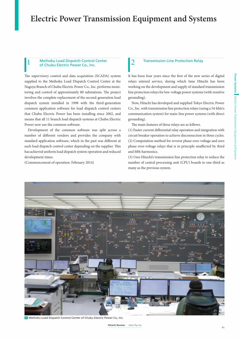
Meihoku Load Dispatch Control Center of Chubu Electric Power Co., Inc.1
Th e supervisory control and data acquisition (SCADA) system supplied to the Meihoku Load Dispatch Control Center at the Nagoya Branch of Chubu Electric Power Co., Inc. performs moni-toring and control of approximately 80 substations. Th e project involves the complete replacement of the second-generation load dispatch system installed in 1998 with the third-generation common application soft ware for load dispatch control centers that Chubu Electric Power has been installing since 2002, and means that all 11 branch load dispatch systems at Chubu Electric Power now use the common soft ware.
Development of the common soft ware was split across a number of diff erent vendors and provides the company with standard application soft ware, which in the past was diff erent at each load dispatch control center depending on the supplier. Th is has achieved uniform load dispatch system operation and reduced development times.(Commencement of operation: February 2014)
Transmission Line Protection Relay2It has been four years since the fi rst of the new series of digital relays entered service, during which time Hitachi has been working on the development and supply of standard transmission line protection relays for low-voltage power systems (with resistive grounding).
Now, Hitachi has developed and supplied Tokyo Electric Power Co., Inc. with transmission line protection relays (using a 54-kbit/s communication system) for main-line power systems (with direct grounding).
Th e main features of these relays are as follows.(1) Faster current diff erential relay operation and integration with circuit breaker operation to achieve disconnection in three cycles.(2) Computation method for reverse phase over-voltage and zero phase over-voltage relays that is in principle unaff ected by third and fi ft h harmonics.(3) Uses Hitachi’s transmission line protection relay to reduce the number of central processing unit (CPU) boards to one-third as many as the previous system.
Electric Power Transmission Equipment and Systems
Meihoku Load Dispatch Control Center of Chubu Electric Power Co., Inc.1
66 Power Systems
Electric Power Transm
ission Equip
ment and
Systems
Pow
er Systems
(4) Stainless steel housing frame that helps reduce carbon dioxide (CO2) emissions by eliminating the need for painting.(Commencement of deliveries: August 2014)
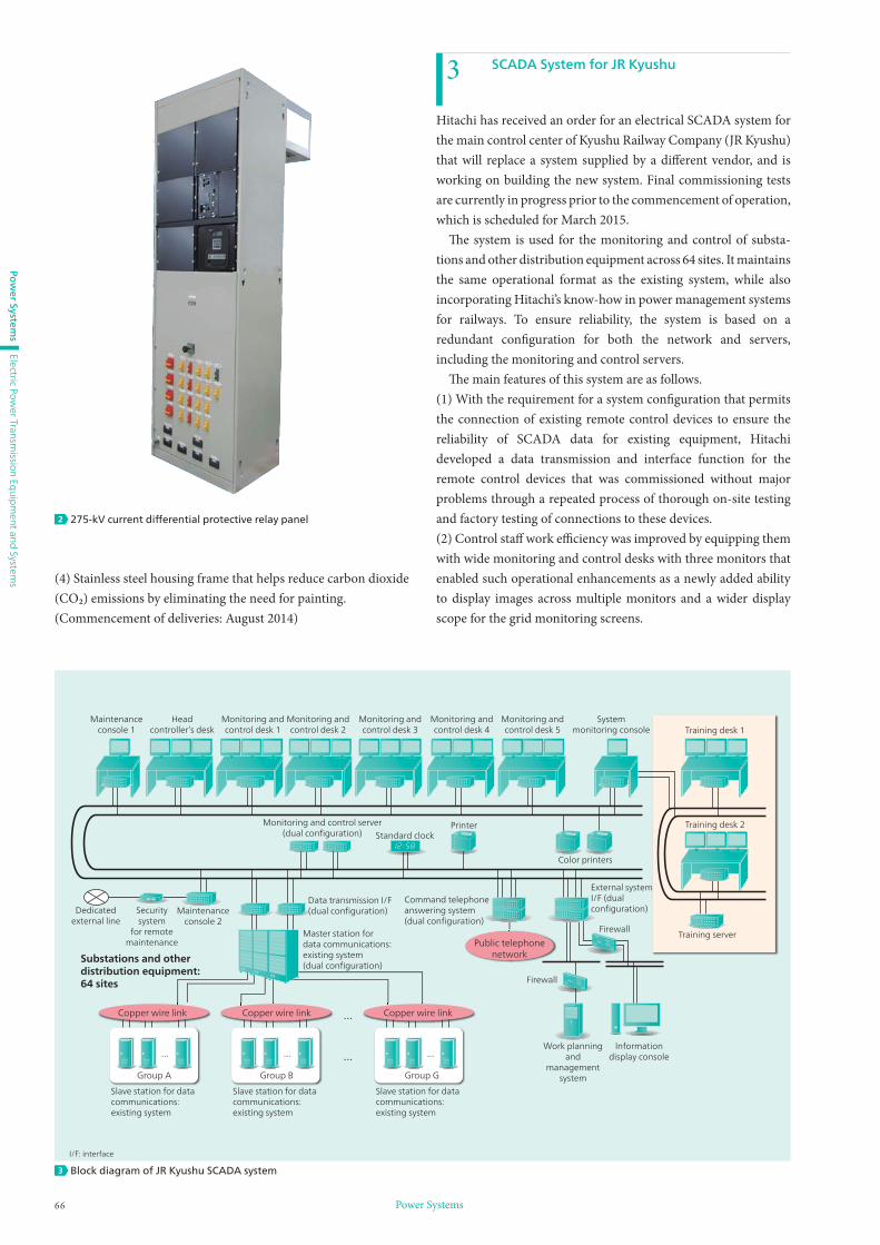
SCADA System for JR Kyushu3Hitachi has received an order for an electrical SCADA system for the main control center of Kyushu Railway Company (JR Kyushu) that will replace a system supplied by a diff erent vendor, and is working on building the new system. Final commissioning tests are currently in progress prior to the commencement of operation, which is scheduled for March 2015.
Th e system is used for the monitoring and control of substa-tions and other distribution equipment across 64 sites. It maintains the same operational format as the existing system, while also incorporating Hitachi’s know-how in power management systems for railways. To ensure reliability, the system is based on a redundant confi guration for both the network and servers, including the monitoring and control servers.
Th e main features of this system are as follows.(1) With the requirement for a system confi guration that permits the connection of existing remote control devices to ensure the reliability of SCADA data for existing equipment, Hitachi developed a data transmission and interface function for the remote control devices that was commissioned without major problems through a repeated process of thorough on-site testing and factory testing of connections to these devices.(2) Control staff work effi ciency was improved by equipping them with wide monitoring and control desks with three monitors that enabled such operational enhancements as a newly added ability to display images across multiple monitors and a wider display scope for the grid monitoring screens.
275-kV current diff erential protective relay panel2
Maintenanceconsole 1
Headcontroller’s desk
Monitoring andcontrol desk 1
Monitoring andcontrol desk 2
Monitoring andcontrol desk 3
Monitoring andcontrol desk 4
Monitoring andcontrol desk 5
Systemmonitoring console Training desk 1
Training desk 2
Training serverFirewall
Color printers
PrinterStandard clock
Firewall
Work planningand
managementsystem
...
...... ......Information
display console
External system I/F (dual configuration)
Data transmission I/F(dual configuration)
Master station fordata communications:existing system(dual configuration)
Copper wire link Copper wire link
Group A Group B Group G
Copper wire link
Public telephonenetwork
Maintenanceconsole 2
Slave station for data communications: existing system
Slave station for data communications: existing system
Slave station for data communications: existing system
Securitysystem
for remotemaintenance
Dedicatedexternal line
Substations and other distribution equipment: 64 sites
Command telephoneanswering system(dual configuration)
Monitoring and control server(dual configuration)
Block diagram of JR Kyushu SCADA system3
I/F: interface

672015 64-03Hitachi Review
Pow
er Systems
Electric Power Transm
ission Equip
ment and
Systems
(3) A dedicated training system was supplied to provide a training environment for control staff . Th e training system provides a training environment that is as close as possible to the actual operation of fi eld equipment, including the addition of a simula-tion function that interoperates with fi eld systems and a fault registration function.
Completion of Compliance Testing for New JEC Standard and Initial Product Deployment of 550-kV GCB for Japanese Market with Oil-immersed Hydraulic Operating Mechanism
4Gas circuit breakers (GCBs) are protection devices for power systems that can perform rapid switching of high power at high voltage. Amid growing demand arising from the replacement of aging equipment in Japan in recent years, Hitachi has released a 550-kV GCB that complies with the latest standard and has undergone type approval testing.
Th e main features of the GCB are as follows.(1) Uses an oil-immersed hydraulic operating mechanism to improve equipment reliability and maintenance. In a move toward maintenance-free operation, the oil-immersed hydraulic operating mechanism has been made more compact and its component count reduced by housing the mechanism inside the case that holds the hydraulic fl uid.(2) To satisfy market requirements, the GCB has been confi rmed to be compliant with the relevant JEC-2300 standard for alter-nating current (AC) circuit breakers, which was revised in 2010, including changes to the interrupt duty such as faults on long-distance lines.(3) Data for assessing the life of components with respect to factors such as the weakest point for insulation and the frequency of operation has been collected to improve reliability and mainte-nance. In the future, Hitachi intends to continue supplying reliable equipment with high added value for such applications as gas-insulated switchgear (GIS) and meeting the increasing demand for the replacement of aging equipment.(Commencement of deliveries: April 2014)
72/84-kV C-GIS with Magnetically Operated VCB5
Hitachi has developed a cubicle-type of gas-insulated switchgear (C-GIS) with a magnetically operated vacuum circuit breaker (VCB).
Th e C-GIS has a rated voltage of 72/84 kV, rated current of 1,200 A, rated interrupting current of 25 kA, and rated sulfur hexafl uoride (SF6) gas pressure of 0.07 MPa. It has passed type testing, which includes a short-circuit test, a dielectric test, a temperature rise test, short-time withstand current and peak withstand current test, and a mechanical operation test.
Th e main features of the C-GIS are as follows.(1) Allows designs with fewer components and maintenance requirements than previous motor-operated spring-charged mechanism VCBs.(2) Reduces on-site maintenance of network connection point current transformer (CT) by fi tting multiple CTs in the gas tank that work with the standard model.(3) Reduces cost as a result of sharing components (including the gas tank) between the network connection unit and transformer primary unit.(4) Achieves short delivery times by consolidating unit manufac-turing.
In the future, Hitachi plans to expand sales of electrical distri-
Installed 550-kV GCB4
EDSmechanism
VCBmechanism
VCB CT CH
2,800 mm
Cubicle width: 850 mm
3,000 mm
EDSES
mechanism
SAR
Magnetically operated VCB (top) and internal design of C-GIS (network connection unit) (bottom)
5
EDS: earthing and disconnecting switch, ES: earthing switch, SAR: surge arrester, CH: cable head

68 Power Systems
Electric Power Transm
ission Equip
ment and
Systems
Pow
er Systems
bution equipment for diff erent uses, including factories, offi ce buildings, transportation, and the public sector.
Train-mounted VCB Capable of Withstanding Low Temperatures and High Altitudes6
Hitachi has been supplying high-voltage VCBs for commuter and Shinkansen railways since the 1970s. Hitachi has also developed models for use in high-speed railways in China, having supplied several thousand units since 2005.
Although most high-speed railways in China to date have operated between the coastal cities, the extension of this network to inland regions is planned. Accordingly, Hitachi has now developed a VCB for the line that has the most stringent environ-mental requirements and runs between Lanzhou and Xinjiang. Th e major diff erences are those required to cope with the temper-atures, air pressures, and other environmental factors encoun-tered at altitudes of 3,000 m or more.
Measures adopted to ensure reliable operation in a harsh envi-ronment included materials that can withstand low temperatures and an insulation design that takes account of the high altitude. To maintain the 300,000-cycle operating life that is one of the features of existing models, Hitachi is also conducting fi eld testing of VCBs in operational trains, as well as performing a variety of in-house testing that includes environmental testing and contin-uous operation testing.
While seeking to win orders for use of its newly developed low-temperature/high-altitude VCBs on the Lanzhou-Xinjiang Railway line, Hitachi also plans to market them for use on other railway lines in inland China.
Use of Vacuum Valves in High-voltage Applications7
Hitachi has been producing vacuum valves for 46 years since commencing production in 1968. Vacuum valves are widely used as a core component in the VCBs that play a critical role in electric power distribution systems in the electric power and electrical machinery sectors. Now, Hitachi has constructed a new factory that commenced operation in August 2014 with the aim of utilizing VCBs with low environmental load and easy mainte-nance, not only in medium-voltage (1 to 52 kV) but also in high-voltage applications (72/84 kV or higher).
Hitachi has sought to add value to its vacuum valves in a variety of ways in the past, including incorporating multiple functions and extending their operating life, while also supplying models that can be used with confi dence in harsh environments such as in the power system equipment installed in trains, ships, or tropical regions. Hitachi also intends to continue working on research and development so that it can provide a greater number of customers with excellent products that incorporate its vacuum valves.
Low-viscosity Silicone Liquid-immersed Transformer with On-load Tap Changer8
Targeting green innovation, Hitachi has developed a low-viscosity silicone liquid-immersed transformer (66 kV, 25 MVA, with
No. Parameter Standard model
1Rated
voltage30 kV
New low-temperature/high-altitude model
←
2Rated
current200 A ←
3Operating
life300,000 cycles ←
4Storage
temperature
–25 to +40°C(same temperatures
as in operation)
–40 to +40°C(–25 to +45°C in operation)
5 Altitude < 1,500 m
< 3,610 m(testing conducted at 4,000 m)
(4,000 m requires 1.38 timesthe pressure tolerance of 1,500 m)
Train-mounted VCB capable of withstanding low temperatures and high altitudes
6
Single-function vacuum valve
World-first* multi-function C-VIS vacuum valve
Use of vacuum valves in high-voltage applications7
* Based on research by Hitachi, Ltd.

692015 64-03Hitachi Review
Pow
er Systems
Electric Power Transm
ission Equip
ment and
Systems
on-load tap changer) that is designed for fi re safety, low environ-mental load, and energy effi ciency, and which is intended for use in the on-site electrical conversion system at the National Institute of Advanced Industrial Science and Technology.
Th e main features of the low-viscosity silicone liquid that serves as the main insulator in the transformer are as follows.(1) Has a high fl ash point (250°C) to allow use as a “designated combustible material.”(2) Complies with Japanese Industrial Standards (JIS), with a high degree of oxidation stability for long life.(3) Has low environmental load (hydrolyzable), is recyclable, and is not a greenhouse gas.
(4) Allows for smaller transformer design (with an installation footprint approximately 80% of a gas-insulated transformer).
Th e insulator in the insulation cylinders of the on-load tap changers (important ancillary components) is suited to the sliding operation performed when changing taps. Th e maintenance and running costs have also been reduced by eliminating the liquid fi lter unit, instead using a vacuum valve design with a synthetic ester that has a high fl ash point (300°C) and low environmental load (biodegradable).
In the future, Hitachi intends to continue developing highly reliable power transformers that satisfy customer needs.
154-kV-class Earthquake-resistant Transformer for Tohoku Electric Power Co., Inc.9
Prompted by the considerable damage to social infrastructure caused by the Great East Japan Earthquake, there has been growing demand for improvements to the seismic performance of power system transformers in the 154-kV and higher classes. Given these needs, Hitachi has developed a 154-kV/150-MVA earthquake-resistant transformer for Tohoku Electric Power Co., Inc.
Th e main features of the transformer are as follows.(1) Uses small and lightweight direct-molded bushings made of a new material and polymer-molded lightning arresters to prevent resonance with the dominant frequency of earthquakes by increasing the natural frequency of individual components. Earthquake resistance has also been improved by lowering the center of gravity of the transformer.(2) Improvements to the internal integrity of the transformer by use of a pressure release mechanism with automatic recovery to release the pressure resulting from any oscillation of the insulating oil inside the transformer during an earthquake and immediately self-recover.(3) As another new technology for improving seismic perfor-mance, it uses vacuum valve on-load tap changers, which improve maintenance by eliminating the need for a live line oil cleaner.
In the future, Hitachi intends to continue developing highly reliable power transformers that satisfy a variety of needs.
Inside transformer: Low-viscosity silicone liquid
Tap changer
Inside on-load tap changer: Synthetic ester
Winding
Core
Transformer Change-over selector
25-MVA, 64.5-kV low-viscosity silicone liquid-immersed transformer with on-load tap changer
Internal structure and exterior of low-viscosity silicone liquid-immersed transformer with on-load tap changer
8
154-kV direct-molded bushing*
Pressure release mechanism with automatic recovery
112-kV polymer-molded lightning arresters
Vacuum valve on-load tap changer (internal)
154-kV-class earthquake-resistant transformer for Tohoku Electric Power Co., Inc.9
* Jointly developed by Hitachi, Ltd. and SWCC Showa Cable Systems Co., Ltd.