Energy Security “Electrical...
34
Dr. Bill Kramer Senior Research Engineer Distributed Energy Systems Integration Energy Security “Electrical Islanding” Approach and Assessment Tools
Transcript of Energy Security “Electrical...
Dr. Bill Kramer
Senior Research Engineer
Distributed Energy Systems Integration
Energy Security “Electrical Islanding”
Approach and Assessment Tools
Renewable Technology Integration
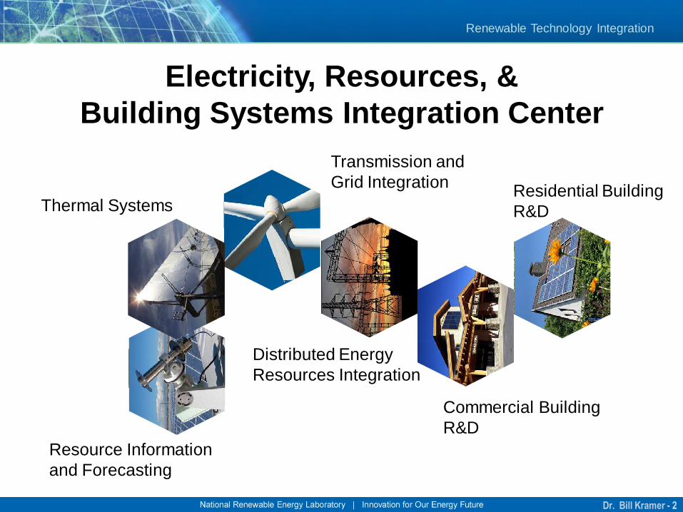
Electricity, Resources, &
Building Systems Integration Center
Resource Information
and Forecasting
Thermal Systems
Transmission and
Grid Integration
Distributed Energy
Resources Integration
Commercial Building
R&D
Residential Building
R&D
Dr. Bill Kramer - 2
Renewable Technology Integration
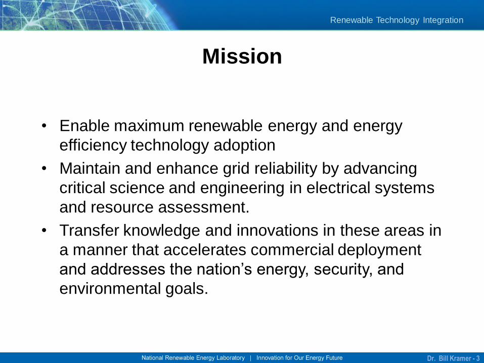
Mission
• Enable maximum renewable energy and energy
efficiency technology adoption
• Maintain and enhance grid reliability by advancing
critical science and engineering in electrical systems
and resource assessment.
• Transfer knowledge and innovations in these areas in
a manner that accelerates commercial deployment
and addresses the nation’s energy, security, and
environmental goals.
Dr. Bill Kramer - 3
Renewable Technology Integration
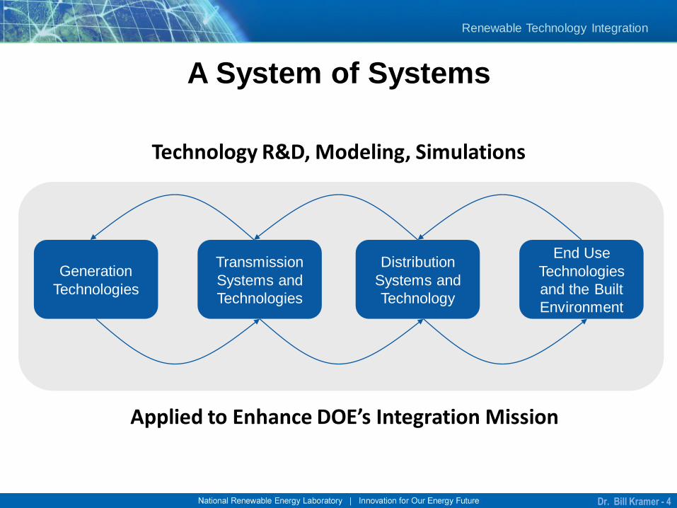
A System of Systems
Generation
Technologies
End Use
Technologies
and the Built
Environment
Transmission
Systems and
Technologies
Distribution
Systems and
Technology
Applied to Enhance DOE’s Integration Mission
Technology R&D, Modeling, Simulations
Dr. Bill Kramer - 4
Renewable Technology Integration
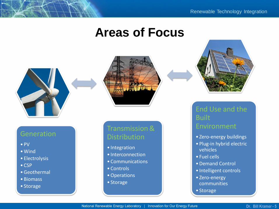
Generation
•PV
•Wind
•Electrolysis
•CSP
•Geothermal
•Biomass
• Storage
Transmission & Distribution
• Integration
• Interconnection
•Communications
•Controls
•Operations
• Storage
End Use and the Built Environment
• Zero-energy buildings
•Plug-in hybrid electric vehicles
• Fuel cells
•Demand Control
• Intelligent controls
• Zero-energy communities
• Storage
Areas of Focus
Dr. Bill Kramer - 5
Renewable Technology Integration
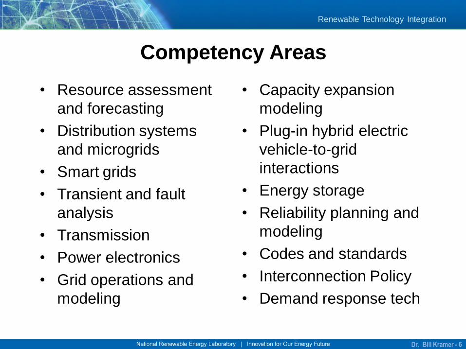
• Resource assessment
and forecasting
• Distribution systems
and microgrids
• Smart grids
• Transient and fault
analysis
• Transmission
• Power electronics
• Grid operations and
modeling
• Capacity expansion
modeling
• Plug-in hybrid electric
vehicle-to-grid
interactions
• Energy storage
• Reliability planning and
modeling
• Codes and standards
• Interconnection Policy
• Demand response tech
Competency Areas
Dr. Bill Kramer - 6
Renewable Technology Integration
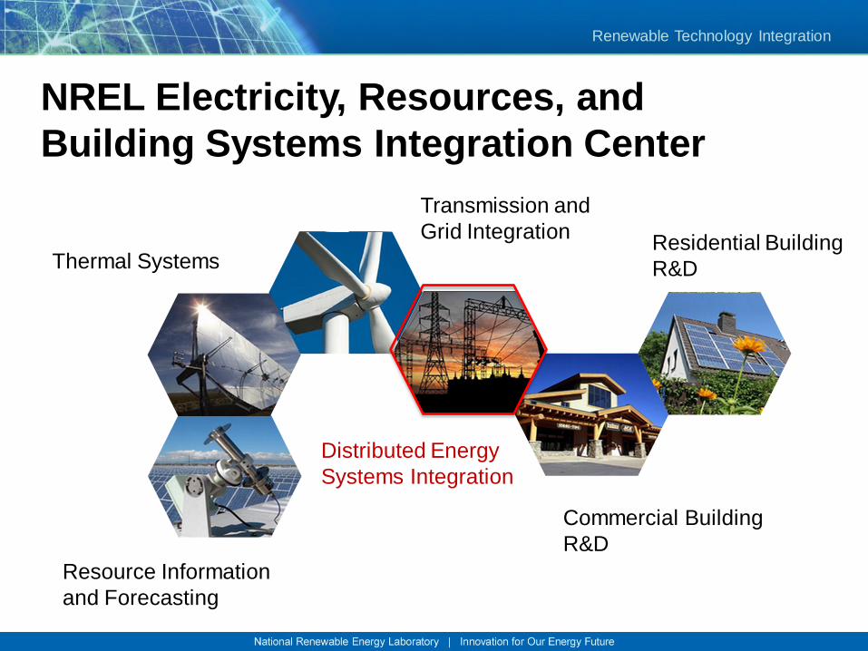
NREL Electricity, Resources, and
Building Systems Integration Center
Resource Information
and Forecasting
Thermal Systems
Transmission and
Grid Integration
Distributed Energy
Systems Integration
Commercial Building
R&D
Residential Building
R&D
Renewable Technology Integration
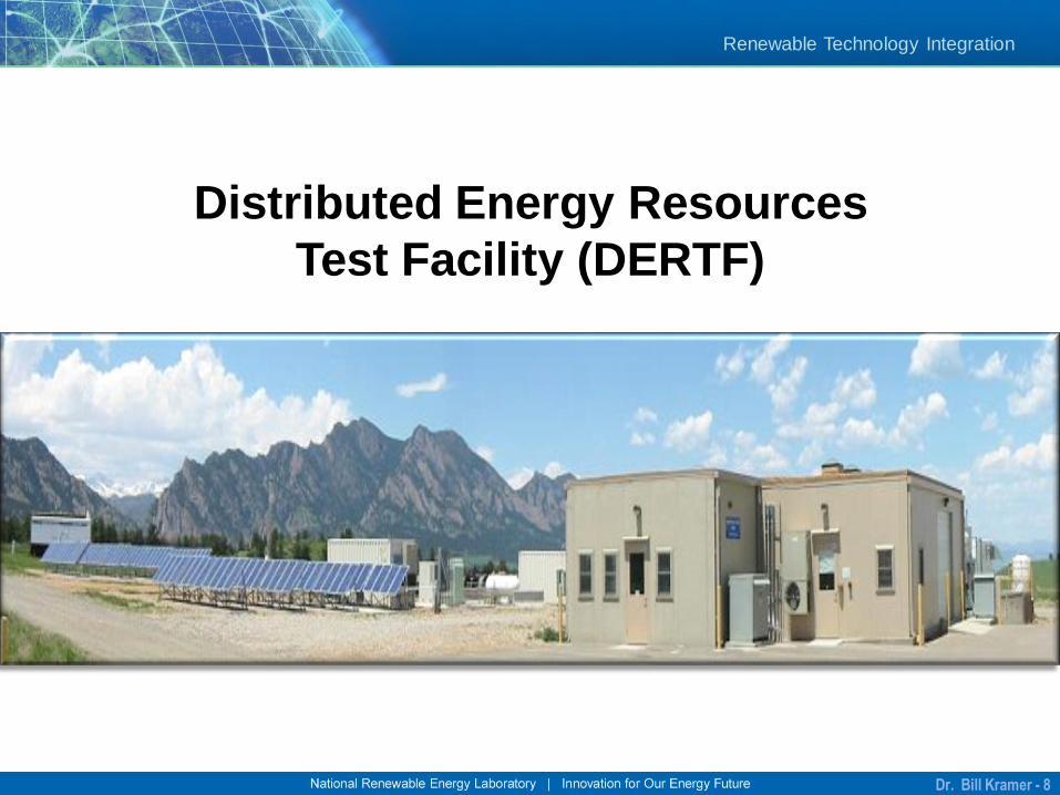
Distributed Energy Resources
Test Facility (DERTF)
Dr. Bill Kramer - 8
Renewable Technology Integration
Distributed Energy Systems
• Distributed energy systems integration
• Power electronics
• Renewable electrolysis for H2 production
• Codes and standards
• Distributed systems modeling
Dr. Bill Kramer - 9
Renewable Technology Integration
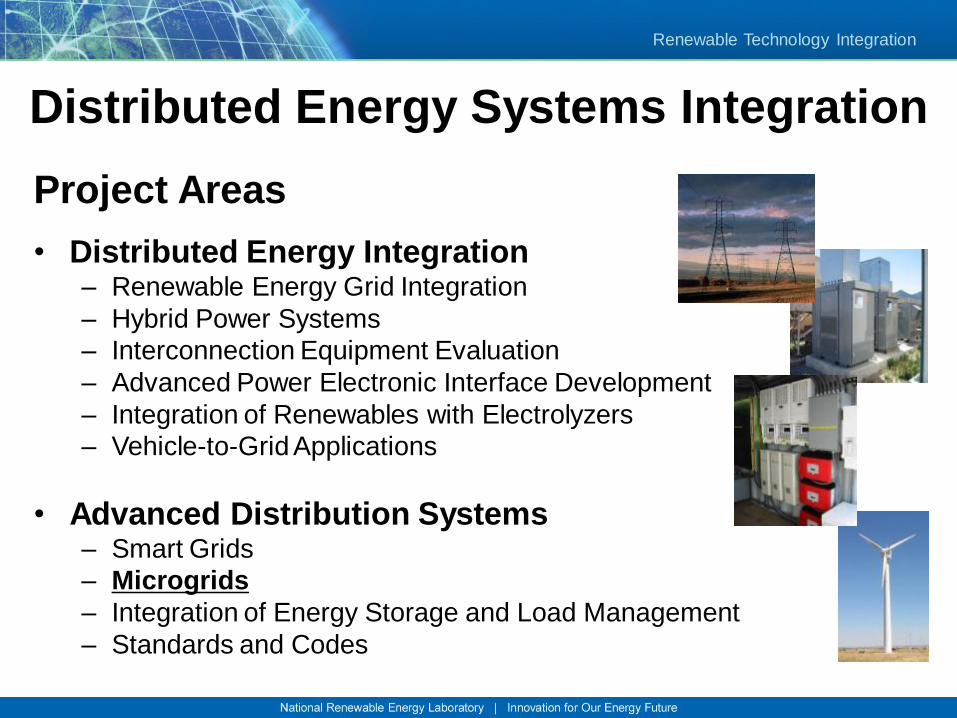
Distributed Energy Systems Integration
Project Areas
• Distributed Energy Integration – Renewable Energy Grid Integration
– Hybrid Power Systems
– Interconnection Equipment Evaluation
– Advanced Power Electronic Interface Development
– Integration of Renewables with Electrolyzers
– Vehicle-to-Grid Applications
• Advanced Distribution Systems – Smart Grids
– Microgrids
– Integration of Energy Storage and Load Management
– Standards and Codes
Renewable Technology Integration
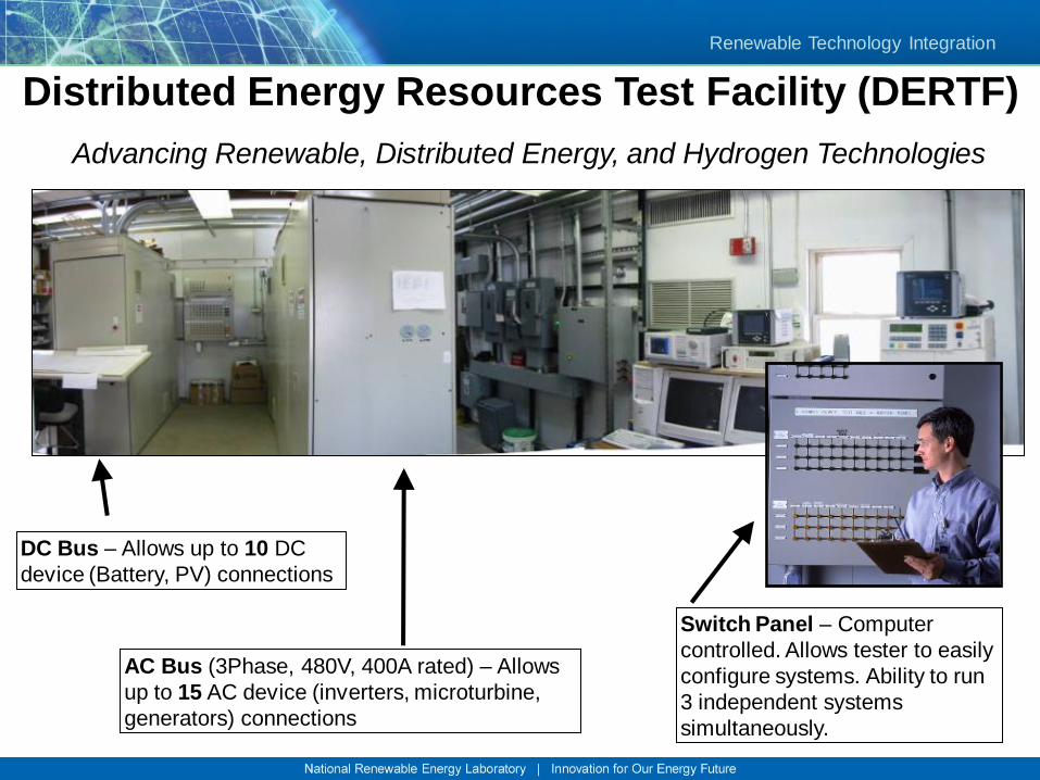
Distributed Energy Resources Test Facility (DERTF)
Advancing Renewable, Distributed Energy, and Hydrogen Technologies
DC Bus – Allows up to 10 DC
device (Battery, PV) connections
AC Bus (3Phase, 480V, 400A rated) – Allows
up to 15 AC device (inverters, microturbine,
generators) connections
Switch Panel – Computer
controlled. Allows tester to easily
configure systems. Ability to run
3 independent systems
simultaneously.
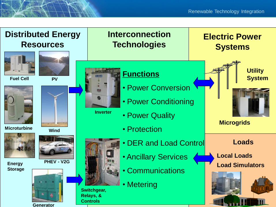
Renewable Technology Integration
Distributed Energy
Resources
Interconnection
TechnologiesElectric Power
Systems
Fuel Cell PV
MicroturbineWind
Generator
Inverter
Switchgear,
Relays, &
Controls
Functions
• Power Conversion
• Power Conditioning
• Power Quality
• Protection
• DER and Load Control
• Ancillary Services
• Communications
• Metering
Microgrids
Energy
Storage
Loads
Local Loads
Load Simulators
Utility
System
PHEV - V2G
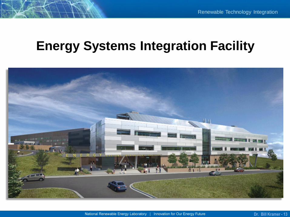
Renewable Technology Integration
Energy Systems Integration Facility
Dr. Bill Kramer - 13
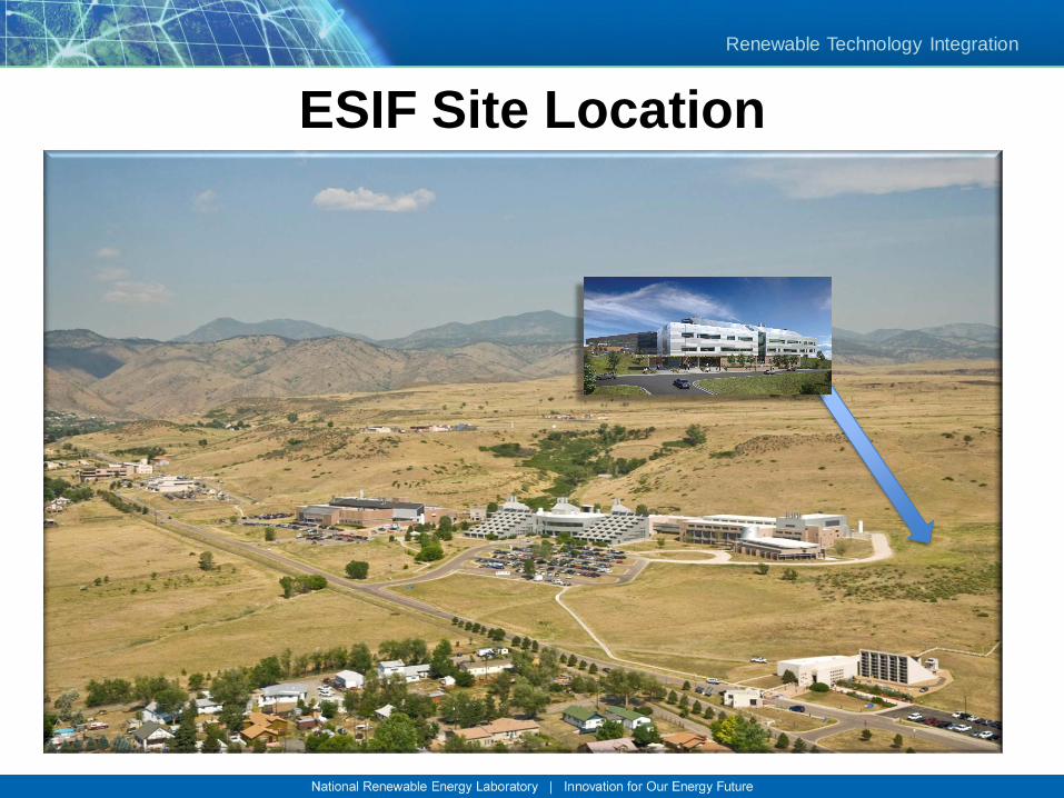
Renewable Technology Integration
ESIF Site Location
Renewable Technology Integration
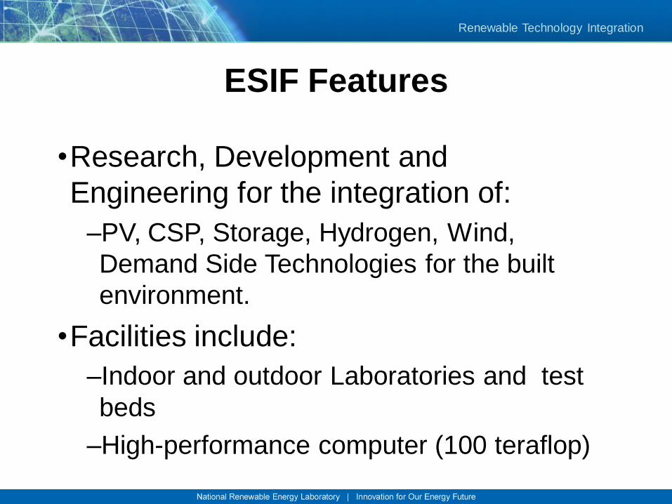
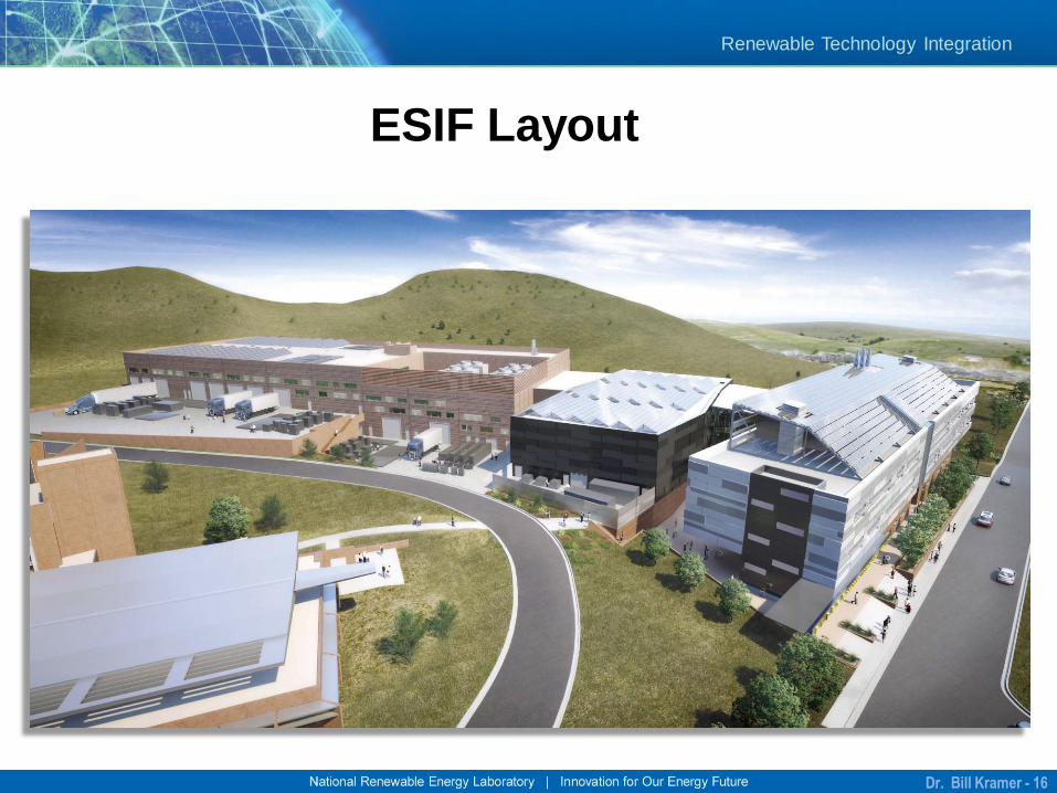
ESIF Features
•Research, Development and
Engineering for the integration of:
–PV, CSP, Storage, Hydrogen, Wind,
Demand Side Technologies for the built
environment.
•Facilities include:
–Indoor and outdoor Laboratories and test
beds
–High-performance computer (100 teraflop)
Renewable Technology Integration
ESIF Layout
Dr. Bill Kramer - 16
Renewable Technology Integration
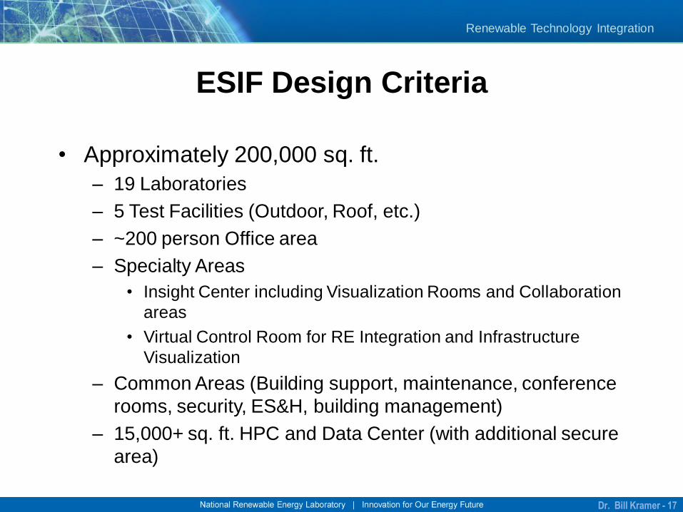
ESIF Design Criteria
• Approximately 200,000 sq. ft.
– 19 Laboratories
– 5 Test Facilities (Outdoor, Roof, etc.)
– ~200 person Office area
– Specialty Areas
• Insight Center including Visualization Rooms and Collaboration
areas
• Virtual Control Room for RE Integration and Infrastructure
Visualization
– Common Areas (Building support, maintenance, conference
rooms, security, ES&H, building management)
– 15,000+ sq. ft. HPC and Data Center (with additional secure
area)
Dr. Bill Kramer - 17
Renewable Technology Integration
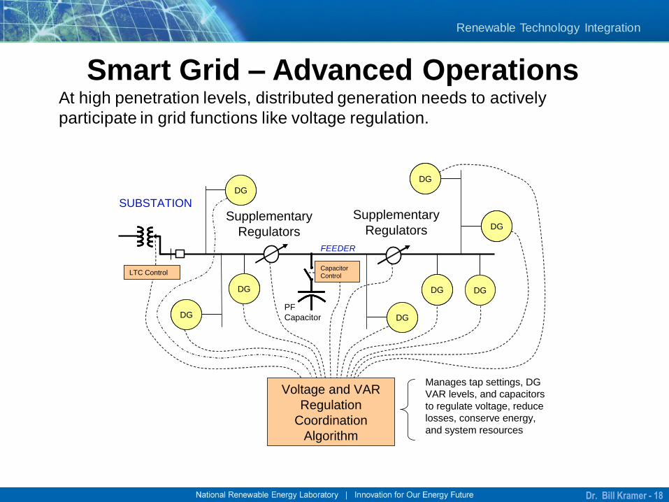
Smart Grid – Advanced Operations
SUBSTATION
FEEDER
Supplementary
RegulatorsSupplementary
Regulators
DGDGDG DGDGDGDGDGDG
DGDGDG
DGDGDG
DGDGDG
DGDGDG
DGDGDG
Capacitor
ControlLTC Control
Voltage and VAR
Regulation
Coordination
Algorithm
Manages tap settings, DG
VAR levels, and capacitors
to regulate voltage, reduce
losses, conserve energy,
and system resources
PF
Capacitor
At high penetration levels, distributed generation needs to actively
participate in grid functions like voltage regulation.
Dr. Bill Kramer - 18
Renewable Technology Integration
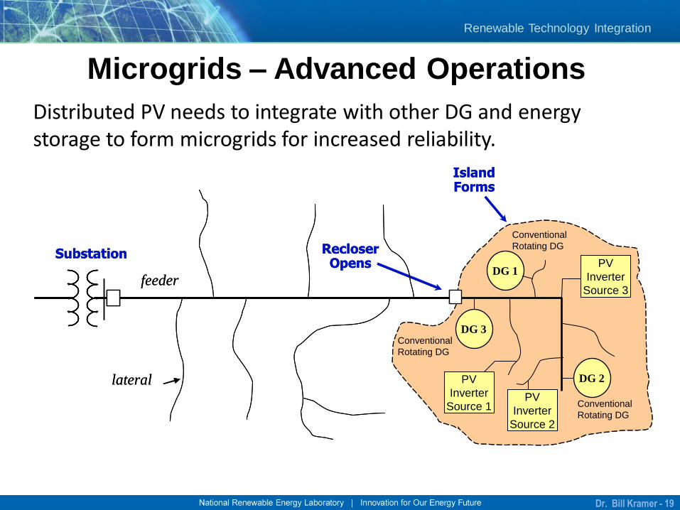
Microgrids – Advanced Operations
Substation
Island Forms
lateral
Recloser Opens
feeder
DG 3
DG 1
DG 2PV
Inverter
Source 1
PV
Inverter
Source 3
PV
Inverter
Source 2
Conventional
Rotating DG
Conventional
Rotating DG
Conventional
Rotating DG
Substation
Island Forms
lateral
Recloser Opens
feeder
DG 3
DG 1
DG 2PV
Inverter
Source 1
PV
Inverter
Source 3
PV
Inverter
Source 2
Conventional
Rotating DG
Conventional
Rotating DG
Conventional
Rotating DG
Distributed PV needs to integrate with other DG and energy storage to form microgrids for increased reliability.
Dr. Bill Kramer - 19
Renewable Technology Integration
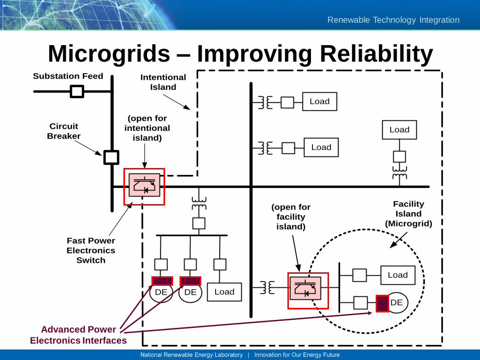
Microgrids – Improving ReliabilitySubstation Feed Intentional
Island
(open for
facility
island)
(open for
intentional
island)
Facility
Island
(Microgrid)
DEDE
DE
Load
Load
Load
Load
Load
Circuit
Breaker
Fast Power
Electronics
Switch
Advanced Power
Electronics Interfaces
Renewable Technology Integration
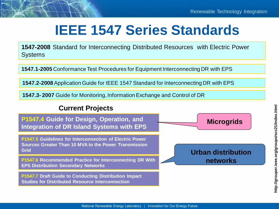
1547-2008 Standard for Interconnecting Distributed Resources with Electric Power
Systems
1547.1-2005 Conformance Test Procedures for Equipment Interconnecting DR with EPS
1547.2-2008 Application Guide for IEEE 1547 Standard for Interconnecting DR with EPS
1547.3- 2007 Guide for Monitoring, Information Exchange and Control of DR
Current Projects
P1547.4 Guide for Design, Operation, and
Integration of DR Island Systems with EPS
P1547.6 Recommended Practice for Interconnecting DR With
EPS Distribution Secondary Networks
P1547.5 Guidelines for Interconnection of Electric Power
Sources Greater Than 10 MVA to the Power Transmission
Grid Urban distribution
networks
Microgrids
htt
p:/
/gro
up
er.
ieee.o
rg/g
rou
ps/s
cc21
/in
dex.h
tml
P1547.7 Draft Guide to Conducting Distribution Impact
Studies for Distributed Resource Interconnection
IEEE 1547 Series Standards
Renewable Technology Integration
IEEE 1547.4 Information
• This document provides alternative approaches and good practices for
the design, operation, and integration of distributed resource (DR)
island systems with electric power systems (EPS). This includes the
ability to separate from and reconnect to part of the area EPS while
providing power to the islanded local EPSs. This guide includes the
distributed resources, interconnection systems, and participating
electric power systems.
• The term “DR island systems”, sometimes referred to as microgrids, is
used for these intentional islands. DR island systems are EPSs that: 1. have DR and load
2. have the ability to disconnect from and parallel with the area EPS
3. include the local EPS and may include portions of the area EPS, and
4. are intentionally planned.
• DR island systems can be either local EPS islands or area EPS
islands.
Renewable Technology Integration
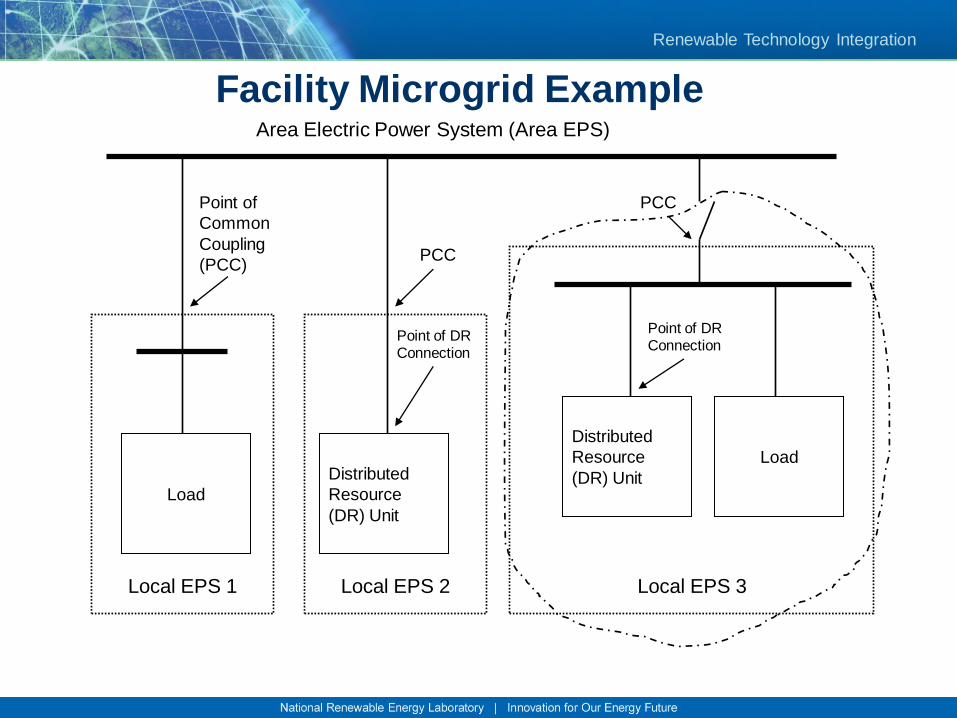
Load
Distributed
Resource
(DR) Unit
Distributed
Resource
(DR) Unit
Load
Point of
Common
Coupling
(PCC)
Point of DR Connection
PCC
PCC
Point of DR Connection
Area Electric Power System (Area EPS)
Local EPS 1 Local EPS 2 Local EPS 3
Facility Microgrid Example
Renewable Technology Integration
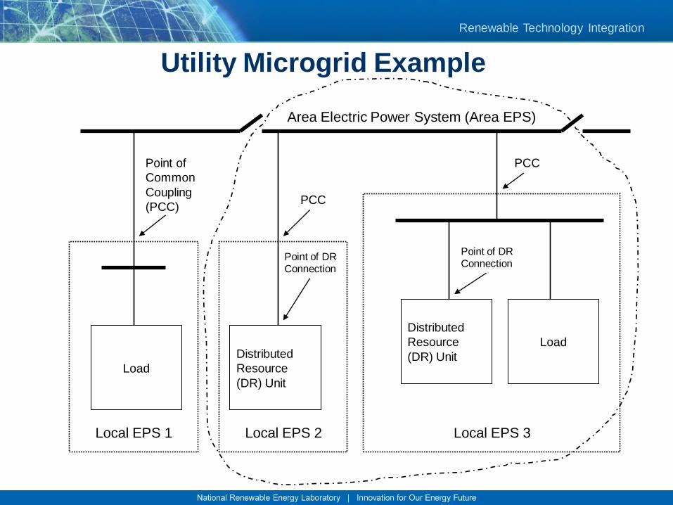
Load
Distributed
Resource
(DR) Unit
Distributed
Resource
(DR) Unit
Load
Point of
Common
Coupling
(PCC)
Point of DR Connection
PCC
PCC
Point of DR Connection
Area Electric Power System (Area EPS)
Local EPS 1 Local EPS 2 Local EPS 3
Utility Microgrid Example
Renewable Technology Integration
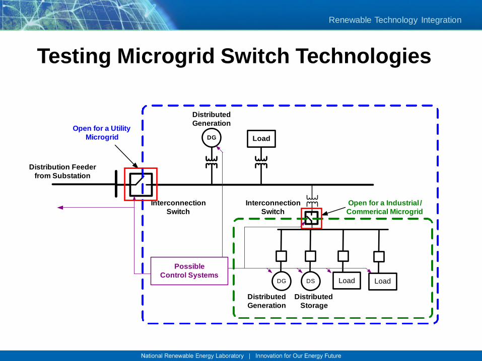
Testing Microgrid Switch Technologies
Distribution Feeder
from Substation
Open for a Utility
Microgrid
DSDG Load Load
DG Load
Interconnection
Switch
Distributed
Generation
Distributed
Generation
Distributed
Storage
Interconnection
Switch
Open for a Industrial /
Commerical Microgrid
Possible
Control Systems
Renewable Technology Integration
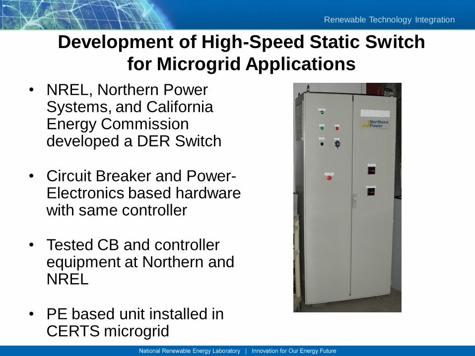
Development of High-Speed Static Switch
for Microgrid Applications
• NREL, Northern Power Systems, and California Energy Commission developed a DER Switch
• Circuit Breaker and Power-Electronics based hardware with same controller
• Tested CB and controller equipment at Northern and NREL
• PE based unit installed in CERTS microgrid
Renewable Technology Integration
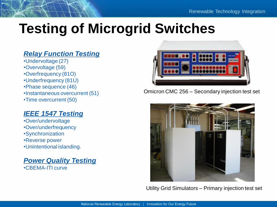
Testing of Microgrid Switches
Relay Function Testing•Undervoltage (27)
•Overvoltage (59)
•Overfrequency (81O)
•Underfrequency (81U)
•Phase sequence (46)
•Instantaneous overcurrent (51)
•Time overcurrent (50)
IEEE 1547 Testing•Over/undervoltage
•Over/underfrequency
•Synchronization
•Reverse power
•Unintentional islanding.
Power Quality Testing•CBEMA-ITI curve
Omicron CMC 256 – Secondary injection test set
Utility Grid Simulators – Primary injection test set
Renewable Technology Integration
Microgrid Symposium
• DOE/LBNL/NREL sponsor an international
microgrid symposium every year since
2005.
• Last year was in San Diego, CA
• Information and Presentations from all
prior symposiums can be found at:
• http://der.lbl.gov/new_site/DER.htm
Renewable Technology Integration
Distributed Energy Workstation
• DEW is a steady-state electrical simulation environment capable of
solving very large and complex distribution system models. DEW
algorithms include:
– Time-varying Load Flow
– PV Impact Analysis
– Protection/Coordination Analysis
– Contingency Analysis
– Reconfiguration for Restoration or Minimum Loss
• DEW can be used to:
– Evaluate resource placement and electrical interconnection
– Analyze the impacts of distributed resources on the existing base
infrastructures
– Identify and evaluate opportunities to improve load and renewable resource
coincidence
Dr. Bill Kramer - 29
Renewable Technology Integration
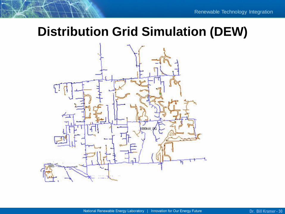
Distribution Grid Simulation (DEW)
Dr. Bill Kramer - 30
Renewable Technology Integration
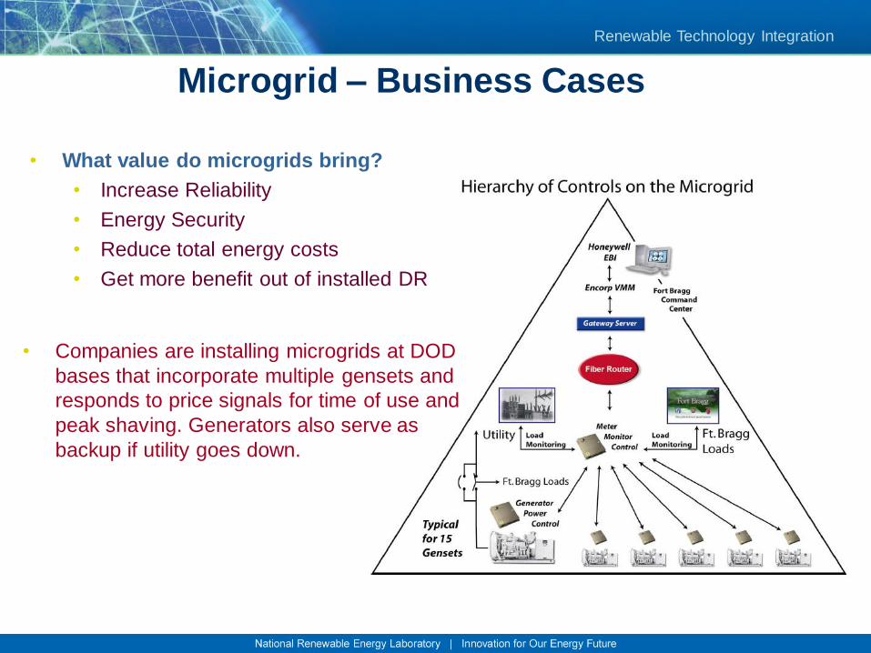
Microgrid – Business Cases
• Companies are installing microgrids at DOD
bases that incorporate multiple gensets and
responds to price signals for time of use and
peak shaving. Generators also serve as
backup if utility goes down.
• What value do microgrids bring?
• Increase Reliability
• Energy Security
• Reduce total energy costs
• Get more benefit out of installed DR
Renewable Technology Integration
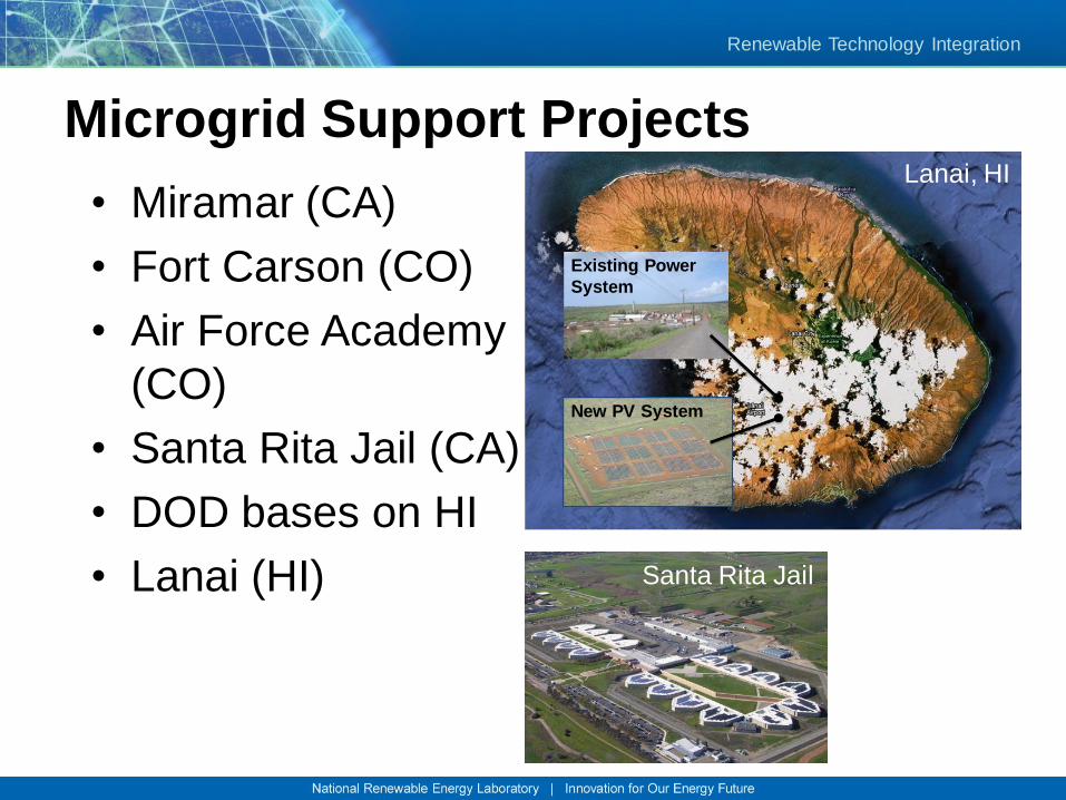
Microgrid Support Projects
• Miramar (CA)
• Fort Carson (CO)
• Air Force Academy
(CO)
• Santa Rita Jail (CA)
• DOD bases on HI
• Lanai (HI)
Existing Power
System
New PV System
Santa Rita Jail
Lanai, HI
Renewable Technology Integration
Technology Path Forward
Dr. Bill Kramer - 33
Renewable Technology Integration
For more information contact:
Dr. Bill Kramer
Senior Research Engineer &
Energy Systems Integration Task Leader
(303) 275 3844
National Renewable Energy Laboratory
Energy, Resources Buildings Systems Integration Center
Distributed Energy Resources Group
Dr. Bill Kramer - 34