
Energy Savings with Thin Gauge - arnoldmagnetics.com · Motors, Generators, ... •Product...
76
© 2009 Arnold Magnetic Technologies 1 Our world touches your world every day… Energy Savings with Thin Gauge for Motors, Generators, Transformers and Inductors Steve Constantinides, Director of Technology Arnold Magnetic Technologies • Demand for electrical device efficiency gains which started decades ago due to economic factors have accelerated, propelled by the unprecedented rise in energy costs and the alleged impact of energy consumption on global weather instability. • Arnold’s thin gage silicon-iron products, both grain-oriented and non-grain oriented (Arnon) offer substantial advantages in many applications.
Transcript of Energy Savings with Thin Gauge - arnoldmagnetics.com · Motors, Generators, ... •Product...

© 2009 Arnold Magnetic Technologies
1Our world touches your world every day…
Energy Savings with Thin Gaugefor
Motors, Generators, Transformers and Inductors
Steve Constantinides, Director of TechnologyArnold Magnetic Technologies
• Demand for electrical device efficiency gains which started decades ago due to economic factors have accelerated, propelled by the unprecedented rise in energy costs and the alleged impact of energy consumption on global weather instability.
• Arnold’s thin gage silicon-iron products, both grain-oriented and non-grain oriented (Arnon) offer substantial advantages in many applications.

© 2009 Arnold Magnetic Technologies
2
Agenda
• Introduction
• GOES versus NGOES
• Manufacturing Process
• Motor & Transformer Efficiency
• Loss Factors
• NGO Thin Gauge (Arnon)
• Over the last several years I’ve spoken about permanent magnets. However, the magnetic material that is utilized in far great tonnage than magnets is the family of soft magnetic materials, especially Silicon-Iron whose usage spans both motor/generator and transformer/inductor applications.
• Often referred to as Electrical Steel, Silicon-Iron (Si-Fe) is available in both Grain Oriented (GOES) and Non-Oriented (NGOES) forms.
© 2009 Arnold Magnetic Technologies
3
Who is Arnold?
• Arnold Magnetic Technologies Corp. is one of the largest manufacturers and suppliers of magnetic materials
• Our headquarters and 5 manufacturing locations are in the USA, but we have a global presence with operations in Switzerland, the United Kingdom and China
• Our products include both permanent and soft magnetic products and assemblies
• The Precision Thin Metals Division has been in operation since the early 1960’s and specializes in thin gauge alloy strip and foil
– Thin meaning from 0.007” down to less than 0.000085”
– Super efficient Si-Fe is available in thicknesses from 0.007” down to 0.001”
Visit the Arnold website to learn more about our products!Find out how we can help you achieve your product performance goals.
• Arnold started as a privately owned manufacturer over 100 years ago in northern Illinois.
• The founder, Bion Arnold, was a world famous electrical engineer and inventor. His son, Robert, took over the running of the company until the late 1960’s.
• In the 1950’s, Arnold was sold to Allegheny Steel Company (Allegheny Ludlum,Allegheny International) and remained part of Allegheny until 1986.
• It was during the Allegheny ownership period that Arnold developed its rolling mill capabilities and many of the electrical steel grades such as Arnon 5 and Arnon 7.
• Product development continued and today Arnold’s Rolled Products Division provides the highest available quality strip and foil in dozens of materials, both magnetic and non-magnetic.

© 2009 Arnold Magnetic Technologies
4Our world touches your world every day…
Two Main Applications for Electrical Steel
Handbook of Small Electric Motors
Switched Reluctance Motorsand their Control, p.154T.J.E. Miller
• There are two major uses for Electrical Steel: Transformers/Inductors and Motors/Generators.
• Transformers are used not only for Electrical Power Distribution, but in virtually every power supply in every electrically powered electronic device in offices and homes.
• Motors have moved from industrial uses in the 1800 and early 1900’s to home and automotive uses. In homes for example, we use motors in garage door openers, washing machines and dryers, furnaces for home heating, refrigerator compressor pumps, bathroom exhaust fans, garbage disposals, and electric powered shop tools.
• Motor usage in automobiles has expanded to include windshield wiper motors, seat adjusting motors, starters, cooling fans, passenger compartment fans, alternators, etc. Note however, many of these use low carbon steel cans for low cost with laminations reserved for higher output, higher efficiency motors/generators.
• The newest example of lamination steel use in cars is the electric drive motor of hybrids or full electric vehicles.
© 2009 Arnold Magnetic Technologies
5Our world touches your world every day…
Agenda
• Introduction
• Manufacturing Process
• GOES versus NGOES
• Motor & Transformer Efficiency
• Loss Factors
• NGO Thin Gauge (Arnon)
• We’ll briefly discuss the manufacturing processes for Grain Oriented and Non-Grain Oriented Electrical Steel.
• Arnold’s name for NGOES is Arnon.
• In order to achieve the especially advantageous properties of Arno n requires at least 10 manufacturing steps.
• To understand why these are necessary requires a basic understanding of the materials.

© 2009 Arnold Magnetic Technologies
6Our world touches your world every day…
GOES Texturing
Distinct texturing of the Si-steel in the direction of rolling
• Silicon-Iron consists of BCC (body-centered cubic) crystals which, during rolling, are stretched and flattened. If they are left in that state, the magnetic properties are maximized but only in the rolling direction, that is along the length of the strip.
• In these two photos we can see the elongated and flattened structure of Grain Oriented Electrical Steel (GOES).

© 2009 Arnold Magnetic Technologies
7Our world touches your world every day…
GOES versus NGOES
• However, when a final annealing heat treat is performed, nearly isotropic properties are achieved within the plane of the strip.
• This is exemplified by the almost total elimination of the grain structure as seen in the photo to the right.

© 2009 Arnold Magnetic Technologies
8Our world touches your world every day…
Understanding the Structure
Pre
ferr
ed d
irec
tion
Rolling direction
• By the 1940’s it was well known that the iron single crystal has a preferred direction along which magnetization is easier than the others – the Goss Structure**. This translates to higher permeability and lower core loss in that given direction, the “cube-on-edge” direction.
• It was recognized that if all the grains in a lamination can be aligned this way, the lamination can be cut to take advantage of this performance enhancement.
• This structure and process were developed to create the preferred orientation in the rolled silicon steel strip. The process involves a combination of cold working and heat treating to produce a strip where most of the metal grains are oriented along the rolling direction.
• While the material is not uniform in all directions, many components such as wound cores and stamped/stacked E cores can be made to maximize the positive aspects of orientation.
• As shown in the illustration at the left, the easy axis (of magnetization) is along the <100> crystal axis.
• The “hard” axis is from one corner to the diagonally opposite corner: the <111> crystal axis.
• To reiterate, effective application of the material requires using the strip in the same direction that flux is expected.
**Norman P. Goss (born February 04, 1906 - died October 28, 1977) - inventor and researcher from Cleveland, USA.
He graduated from Case Institute of Technology in 1925. He made significant contributions to the field of metals research and in 1935 he patented a method[1] and published a paper[2] describing a method of obtaining so-called grain-oriented electrical steel, which has highly anisotropic magnetic properties. This special "grain-oriented" structure was named after its inventor and it is referred to as the "GOSS structure".
The grain-oriented electrical steel allowed development of highly efficient electrical machines, especially transformers. Today , the magnetic cores of all high-voltage high-power transformers are made from grain-oriented electrical steel.
- - Wikipedia - -

© 2009 Arnold Magnetic Technologies
9Our world touches your world every day…
Directional Properties of Si-Steel (GOES)
• This chart from AK steel for grain oriented silicon iron illustrates the difference in magnetic properties in the rolling direction (straight up and down) and at angles at up to 90º from the rolling direction (left to right).
• Maximum performance is achieved by application of the material with the strip in the same direction that flux is expected.
• In contrast, NGOES shows only a 10-20% variation in properties within the plane of the strip.

© 2009 Arnold Magnetic Technologies
10Our world touches your world every day…
Agenda
• Introduction
• GOES versus NGOES
• Manufacturing Process
• Motor & Transformer Efficiency
• Loss Factors
• NGO Thin Gauge (Arnon)
• Reduced eddy current related loss in thin gauge lamination materials such as Arnold’s grades (between 0.001 and 0.007” thick) permit higher frequency operation.
• Silicon-Iron laminations are more expensive than low carbon steel and their use has been reserved for high energy density, high rpm motors and generators and for high frequency transformers.
• In defense of Silicon-Iron manufacturers, the process for making lamination-ready Si-Fe strip involves many processing steps and utilizes expensive manufacturing equipment.
© 2009 Arnold Magnetic Technologies
11Our world touches your world every day…
Manufacturing Steps, NGOES
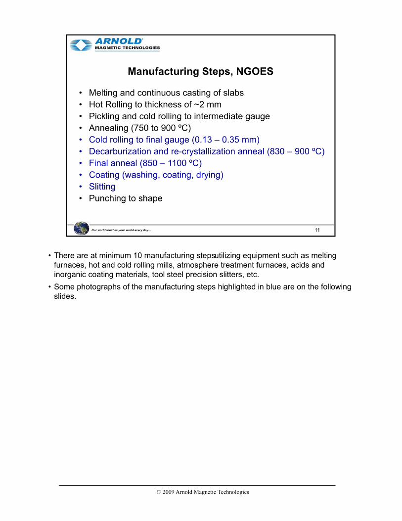
• Melting and continuous casting of slabs
• Hot Rolling to thickness of ~2 mm
• Pickling and cold rolling to intermediate gauge
• Annealing (750 to 900 ºC)
• Cold rolling to final gauge (0.13 – 0.35 mm)
• Decarburization and re-crystallization anneal (830 – 900 ºC)
• Final anneal (850 – 1100 ºC)
• Coating (washing, coating, drying)
• Slitting
• Punching to shape
• There are at minimum 10 manufacturing steps utilizing equipment such as melting furnaces, hot and cold rolling mills, atmosphere treatment furnaces, acids and inorganic coating materials, tool steel precision slitters, etc.
• Some photographs of the manufacturing steps highlighted in blue are on the following slides.

© 2009 Arnold Magnetic Technologies
12Our world touches your world every day…
Decarburization, Re-crystallizationand final Anneal
• Re-crystallization and annealing is performed in continuous atmosphere furnaces such as this one at Arnold.
• The strip can be seen exiting the furnace at the left of this photo…

© 2009 Arnold Magnetic Technologies
13Our world touches your world every day…
Sendzimir Mill Rolling to Final Gauge
www.sendzimir.com
• For thin gauge, specialized rolling mills are used to achieve uniform cross-strip thickness and flawless surfaces on Si-Fe down to 0.001” (0.025 mm).
• Arnold does, incidentally, roll other alloys to as little as 85 millionths of an inch (0.000085”) on Sendzimir mills.
• The Sendzimir mill uses small diameter rolls to reduce the strip thickness. The small rolls are backed-up by larger rolls to eliminate bending of the small rolls under intense compressive stress.
• The use of small diameter inner rolls is required to apply the very high contact pressures required to compress the sheet thickness while it is being stretched by the powerful drive and take-up motors.

© 2009 Arnold Magnetic Technologies
14Our world touches your world every day…
Surface Treatment and Coating
Feed
Coat
Acid washClean
Dry & Fire coating
Cool
Re-Roll
• Surface coating includes steps of acid wash, coating and firing the coating onto the strip.
• The coating system shown here is two stories high and approximately 120 feet long.
• Typical coating for Si-Fe laminations is designated “C-5”.
© 2009 Arnold Magnetic Technologies
15Our world touches your world every day…
Slitting
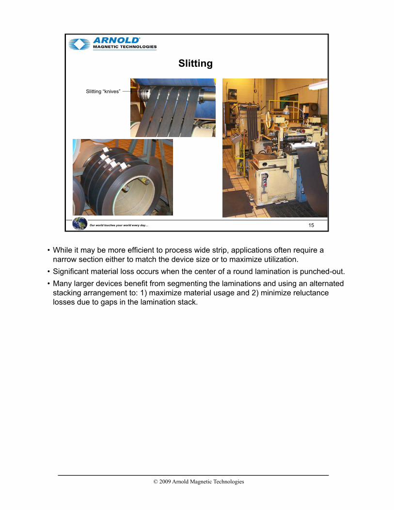
Slitting “knives”
• While it may be more efficient to process wide strip, applications often require a narrow section either to match the device size or to maximize utilization.
• Significant material loss occurs when the center of a round lamination is punched-out.
• Many larger devices benefit from segmenting the laminations and using an alternated stacking arrangement to: 1) maximize material usage and 2) minimize reluctance losses due to gaps in the lamination stack.

© 2009 Arnold Magnetic Technologies
16Our world touches your world every day…
Agenda
• Introduction
• GOES versus NGOES
• Manufacturing Process
• Motor & Transformer Efficiency
• Loss Factors
• NGO Thin Gauge (Arnon)
• Most commercial transformers use low-cost low carbon steel.
• Justification for the use of Si-Fe includes demands for higher device efficiency (motors and transformers) and design feasibility (very high frequency transformers).

© 2009 Arnold Magnetic Technologies
17Our world touches your world every day…
Motor Efficiency
“…~57% of the generated electric energy in the United States is utilized [consumed] by electric motors powering industrial equipment. In addition, more than 95% of an electric motor’s life-cycle cost is the energy cost.”
The Next Generation Motor, IEEE Industry Applications, January / February 2008, p.37

© 2009 Arnold Magnetic Technologies
18Our world touches your world every day…
Electric Operating Cost
Figure 1. First Cost is not the Last Cost
*60 HP; equivalent to 50.18 kW capacity**Based on 2-shift operationArt courtesy of Ontario Hydro
From AEC (North Carolina Alternative Energy Corporation), updated with current gas prices, www.p2pays.org/ref/17/16897.pdf
$2.50
$1000
6%
0
50,000
100,000
150,000
200,000
0 5 10 15 20
Years of Use
Cu
mu
lati
ve C
ost
Motor
Car
Trade-in car at 100,000 miles
Cost of Ownership and Use
• This chart from AEC has been updated with more current gasoline pricing. Electric costs are likely to rise commensurate with gas but have not been changed here.
• It is obvious that more attention must be paid to total operating costs, not just initial purchase price. Our industry needs to help educate the customer to consider more than just initial purchase price.

© 2009 Arnold Magnetic Technologies
19Our world touches your world every day…
Motor Efficiency
Increased Efficiency versus Increased Reliability, IEEE Industry Applications, January / February 2008, p.29
• In 1975 the average efficiency of large electric motors was less than 94% with many operating at 80% or less.
• Today’s premium motors achieve over 96% efficiency and the government is mandating further increases.
© 2009 Arnold Magnetic Technologies
20Our world touches your world every day…
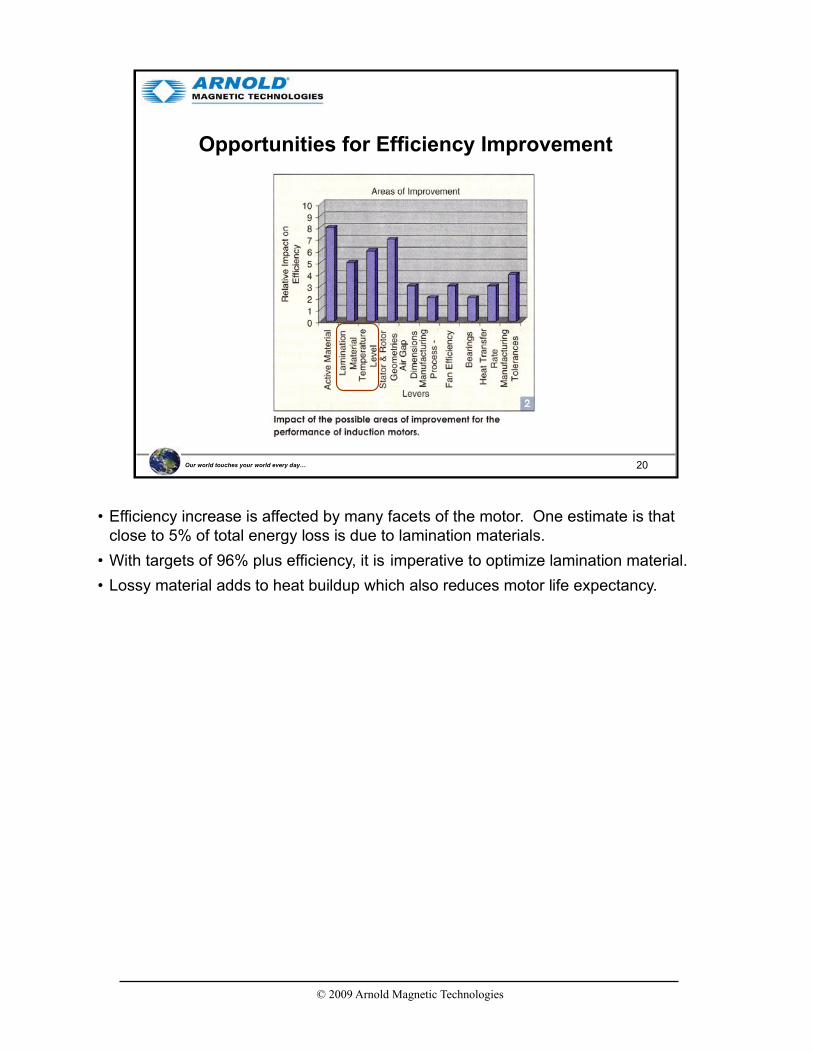
Opportunities for Efficiency Improvement
• Efficiency increase is affected by many facets of the motor. One estimate is that close to 5% of total energy loss is due to lamination materials.
• With targets of 96% plus efficiency, it is imperative to optimize lamination material.
• Lossy material adds to heat buildup which also reduces motor life expectancy.

© 2009 Arnold Magnetic Technologies
21Our world touches your world every day…
Loss Distribution
Increased Efficiency versus Increased Reliability, IEEE Industry Applications, January / February 2008, p.33
• 20% of energy loss in the motors under this study is from Core Loss, most of which is attributed to the lamination material, either directly or indirectly.

© 2009 Arnold Magnetic Technologies
22Our world touches your world every day…
Energy Consumption by Motor Size
• Despite very large numbers of small motors in use today, large industrial motors consume greater amounts of electric power than smaller motors.
• Large industrial motors are more likely to run continuously, while smaller motors may be on a small fraction of time.

© 2009 Arnold Magnetic Technologies
23Our world touches your world every day…
Energy Policy Act Efficiency Targets
Increasing EfficiencyTargets
75.5%
95.0%
• This chart emphasizes the energy efficiency requirements of higher HP motors since that is where the greatest energy savings is expected to accrue.
© 2009 Arnold Magnetic Technologies
24Our world touches your world every day…
Additional Motor Efficiency Information
• Energy Efficient Electric Motor Selection Handbook– www.wbdg.org/ccb/DOE/TECH/ce0384.pdf
• Buying an Energy Efficient Electric Motor– www1.eere.energy.gov/industry/bestpractices/pdfs/mc-0382.pdf
• Consortium for Energy Efficiency– www.cee1.org/ind/mot-sys/mtr-ms-main.php3
• Efficient Electric Motor Systems for Industry– www.osti.gov/bridge/servlets/purl/10112522-FoENQM/webviewable/10112522.PDF
• Efficient Electric Motor Systems: SEEEM– www.asiapacificpartnership.org/BATF/BATF%20Projects%20Workshops/Motors%20
WS-SEEEM-brunner.pdf
• Development of Ultra-Efficient Electric Motors– www.osti.gov/bridge/servlets/purl/928973-hsePV1/928973.PDF
• Electric Motor Systems in Developing Countries: Opportunities for Efficiency Improvement
– www.osti.gov/bridge/servlets/purl/10187187-n23Ohm/native/10187187.PDF
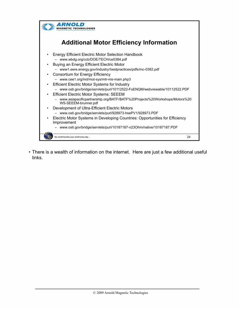
• There is a wealth of information on the internet. Here are just a few additional useful links.

© 2009 Arnold Magnetic Technologies
25Our world touches your world every day…
Transformers
Transformers can be small enough for installation
onto circuit boards or as large as a house
• Transformers and Inductors when used at low frequencies, such as these electric distribution transformers utilize low cost iron laminations and operate with efficiencies of 98% or higher.
• Smaller, special purpose transformers in high frequency and pulse power applications benefit from thin gauge and higher resistivity Si-Fe laminations.
• Examination of this subject would require an entire session by itself, so we will restrict this to just a few slides.

© 2009 Arnold Magnetic Technologies
26Our world touches your world every day…
Transformers on HyperPhysics
http://hyperphysics.phy-astr.gsu.edu/hbase/magnetic/transcon.html#c1
HyperPhysics is hosted by the Department of Physics and Astronomy of Georgia State University
Overview of the subject of Transformers
• Transformers are used to convert lower voltages to higher voltages (step-up transformer) or higher voltages to lower ones (step-down).
• The ratio of turns of wire on the primary (input) to those on the secondary (output) determines which type it is.
• Since power stays the same, when voltage increases, current decreases - - and the converse is true.
• The applied voltage cannot be steady DC: it must be AC or pulsed or varying DC.
• Each of the windings has associated with it an electrical resistance. Under AC (or pulsed DC) conditions, this resistance become inductive (inductance).
• Therefore, a Si-Fe core with a single winding is an inductor.
© 2009 Arnold Magnetic Technologies
27Our world touches your world every day…
Transformers: Examples
30 :1N:1
I2
V2 = 240 voltsCenter-Tapped
I1
V1 = 7200 volts
(1/2)V2 = 120 volts
(1/2)V2 = 120 volts
Photographscourtesyof ABB
Silicon Steel 3-Phase Transformer
Photograph courtesy of Magnetic Metals
From
Small
To
Large
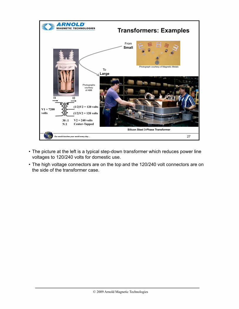
• The picture at the left is a typical step-down transformer which reduces power line voltages to 120/240 volts for domestic use.
• The high voltage connectors are on the top and the 120/240 volt connectors are on the side of the transformer case.

© 2009 Arnold Magnetic Technologies
28Our world touches your world every day…
DOE – Appliances and Commercial Equipment Standards Program
Laws and Regulations
• The Energy Policy and Conservation Act (EPCA) of 1975 established an energy conservation program for major household appliances.
• The National Energy Conservation Policy Act of 1978 amended EPCA to add Part C of Title III, which established an energy conservation program for certain industrial equipment.
• The Energy Policy Act of 1992 amended EPCA to add certain commercial equipment, including distribution transformers.
Bob Saint, Principal Distribution Engineer, Energy Policy, NRECA, April 29, 2008

© 2009 Arnold Magnetic Technologies
29Our world touches your world every day…
DOE Actions on Distribution Transformers
• Energy Conservation Standard – started in 2000.– Framework Document Workshop, November 1, 2000
– Draft analyses published 2001 through 2003
– ANOPR published July 29, 2004Public Meeting, September 28, 2004
– EPAct 2005 establishes standards for Dry-type Transformers effective January 1, 2007
– NOPR, August 4, 2006Public Meeting, September 27, 2006
– Final Rule Published October 12, 2007Effective January 1, 2010
© 2009 Arnold Magnetic Technologies
30Our world touches your world every day…
DOE Efficiency Calculations
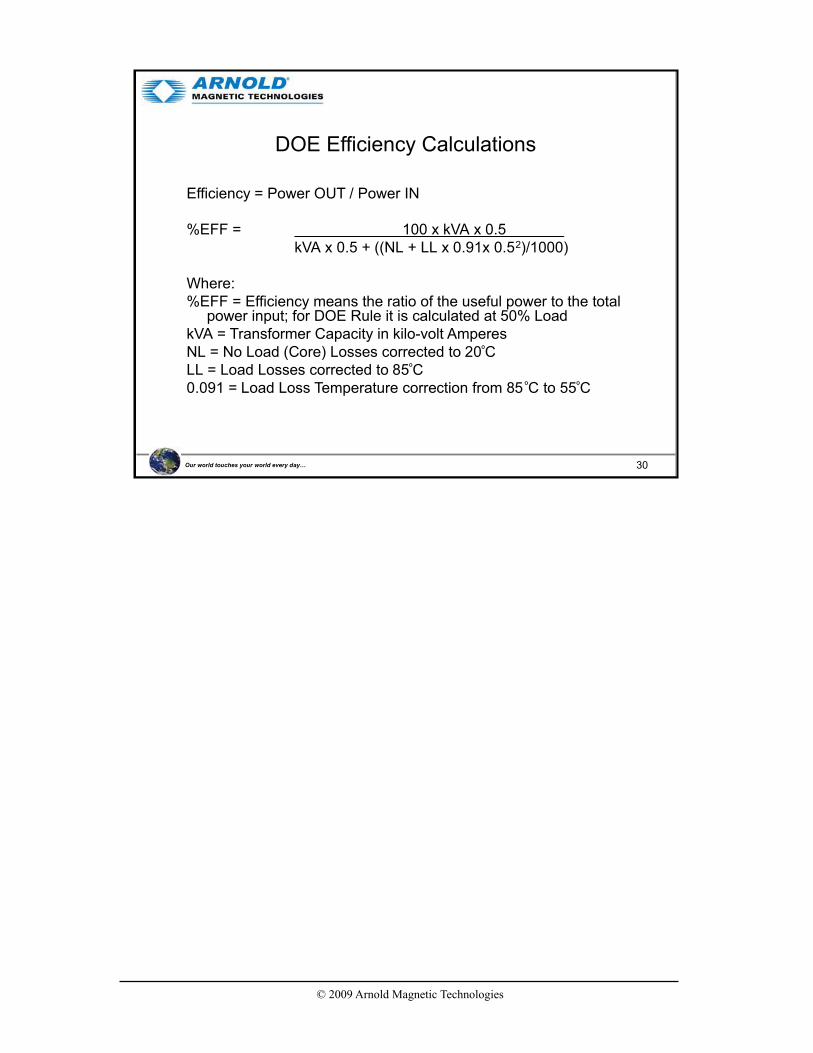
Efficiency = Power OUT / Power IN
%EFF = 100 x kVA x 0.5kVA x 0.5 + ((NL + LL x 0.91x 0.52)/1000)
Where:%EFF = Efficiency means the ratio of the useful power to the total
power input; for DOE Rule it is calculated at 50% LoadkVA = Transformer Capacity in kilo-volt AmperesNL = No Load (Core) Losses corrected to 20ºCLL = Load Losses corrected to 85ºC0.091 = Load Loss Temperature correction from 85 ºC to 55ºC

© 2009 Arnold Magnetic Technologies
31Our world touches your world every day…
Transformer Energy Loss
• Energy loss in a transformer is almost totally converted to heat
• Energy loss is mostly caused by
– Coil Loss
– Eddy current and hysteresis loss
– Winding resistance dominates load losses, whereas hysteresis and eddy currents losses contribute to over 99% of the no-load loss.
• Temperature rise is a rough indicator of transformer efficiency
• Transformer temperature rise is defined as the average temperature rise of the windings above the ambient (surrounding) temperature, when the transformer is loaded at its nameplate rating
– Dry-type transformers are available in three standard temperature rises: 80C, 115C, or 150C
– Liquid-filled transformers come in standard rises of 55C and 65C
• Transformer losses in power distribution networks can exceed 3% of the total electrical power generated and are estimated to total 140 billion kilowatt-hours (kWh) per year in the U.S.
– Converting these transformers to higher efficiency units would reduce wasted electricity by about 61 billion kWh each year.
• Winding resistanceCurrent flowing through the windings causes resistive heating of the conductors. At higher frequencies, skin
effect and proximity effect create additional winding resistance and losses.
• Hysteresis lossesEach time the magnetic field is reversed, a small amount of energy is lost due to hysteresis within the core.
For a given core material, the loss is proportional to the frequency, and is a function of the peak flux density to which it is subjected.
• Eddy currentsFerromagnetic materials are also good conductors, and a solid core made from such a material also
constitutes a single short-circuited turn throughout its entire length. Eddy currents therefore circulate within the core in a plane normal to the flux, and are responsible for resistive heating of the core material. The eddy current loss is a complex function of the square of supply frequency and inverse square of the material thickness.
• MagnetostrictionMagnetic flux in a ferromagnetic material, such as the core, causes it to physically expand and contract
slightly with each cycle of the magnetic field, an effect known as magnetostriction. This produces the buzzing sound commonly associated with transformers, and in turn causes losses due to frictional heating in susceptible cores.
• Mechanical lossesIn addition to magnetostriction, the alternating magnetic field causes fluctuating electromagnetic forces
between the primary and secondary windings. These incite vibrations within nearby metalwork, adding to the buzzing noise, and consuming a small amount of power.
• Stray lossesLeakage inductance is by itself lossless, since energy supplied to its magnetic fields is returned to the
supply with the next half-cycle. However, any leakage flux that intercepts nearby conductive materials such as the transformer's support structure will give rise to eddy currents and be converted to heat.

© 2009 Arnold Magnetic Technologies
32Our world touches your world every day…
Single Phase Efficiency (%)
99.6099.4999.4599.40833
99.5799.4699.4299.40667
99.5499.4299.3899.30500
99.4999.3699.3199.20333
99.4599.3299.2699.20250
99.2599.2599.2199.10167
99.1499.2399.1099.00100
99.0899.1799.0499.0075
99.0499.0898.9098.9050
98.9199.0198.8598.8037.5
98.7998.9198.7398.7025
98.6398.7698.5698.6015
98.4898.6298.4098.4010
TSL4 Final RuleTSL2NEMA TP-1 kVA
• TSL stands for Trial Standard Levels with #1 through 6.
• TSL1 = NEMA TP 1-2002 (industry voluntary standard)
• TSL2 ~1/3 of the efficiency between TP 1 and Min LCC (TSL4)
• TSL3 ~2/3 of the efficiency between TP 1 and Min LCC (TSL4)
• TSL4 ~minimum life-cycle cost (LCC)
• TSL5 ~maximum energy savings with no change in LCC
• TSL6 = maximum technologically feasible

© 2009 Arnold Magnetic Technologies
33Our world touches your world every day…
Three Phase Efficiency (%)
99.5399.4999.4499.402500
99.5199.4699.4099.402000
99.4799.4299.3699.301500
99.4199.3699.2999.201000
99.3799.3299.2499.20750
99.4599.2599.3299.10500
99.3899.2399.2399.00300
99.3399.1799.1799.00225
99.2699.0899.0898.90150
99.2099.0199.0198.80112.5
99.1298.9198.9198.7075
99.0098.7698.7698.6045
98.8998.6298.6298.4030
98.6898.3698.3698.1015
TSL4 Final RuleTSL2NEMA TP-1 kVA
© 2009 Arnold Magnetic Technologies
34Our world touches your world every day…
Agenda
• Introduction
• GOES versus NGOES
• Manufacturing Process
• Motor & Transformer Efficiency
• Loss Factors
• NGO Thin Gauge (Arnon)
• Si-Fe is more expensive than low carbon steel and thin gauge Si-Fe is more expensive than thick gauge.
• Therefore, to justify the usage of thin gauge Si-Fe, there must be an advantage to counterbalance the higher cost.

© 2009 Arnold Magnetic Technologies
35Our world touches your world every day…
Loss Variables by Categories
Input Variables-1 Input Variables-2 Loss contributors Loss
Frequency Eddy Current Loss Heat
Skin Effect
Applied field strength
Hysteresis
Field Orientation (max perm, Hc, Bsat) Hysteretic Loss
Lamination Thickness
Resistivity (Material)
Anomolous Loss
Resistance (Interlam)
Lam Insul Thickness
Lam flatness Stacking Factor Energy Transfer
("Efficiency")
Winding Arrangement
Interlam vibration
Magnetostriction (Noise)
Thermal characteristics
(Material)
Electrical Coil Resistance
Mechanical Friction
Material Resistivity5:
Magnetostriction4:
Laminations3:
Eddy Current2:
Hysteresis1:
a.k.a. Excess Loss
• This slide shows the complex set of variables involved with selecting the proper material grade and thickness.
• Lower efficiency is the result of energy being converted to heat.
• Note that many of the variables are interactive. One variable can affect another variable. For example, switching frequency affects how deep the field will penetrate a lamination which affects required lamination thickness which affects stacking factor, etc.
• That is, the use of thin gauge Si-Fe (Arnon 5 and Arnon 7) can minimize the losses associated with most of these items.
• These variables can be grouped into similar categories for discussion.
• 5 groups have been created here as shown in the upper right of the chart.
• We need to first understand some basics regarding Frequency, so that will be our first topic.

© 2009 Arnold Magnetic Technologies
36Our world touches your world every day…
Waveforms
Table 1.1 Maximum Flux Density Formulas for Commonly Occurring Functions
Note: In these formulas N is the number of turns in the winding across which the voltage is developed. A is the cross-sectional area of the core around which the winding is placed. If the area is expressed in square centimeters, the flux density will be in gauss. If the area is expressed in square inches, the flux density will be in maxwells per square inch. Time t is in seconds. Frequency f is in hertz. Voltage E in in volts. Current Iis in amperes. Inductance L is in henries.
Handbook of Transformer Design & Application, p. 1.6
• Before we begin examining magnetic and electrical properties of the material, it is necessary to understand that the affects upon the material are due to the rate and magnitude of applied field change.
• While we consider a sinusoidal wave form to be most common, developments in electronic controls over the past two decades have allowed application of complex waveforms for both control and efficiency.
• Some of these waveforms produce more rapid field changes than suggested by the over riding frequency. One example of this is a pulse field waveform.
© 2009 Arnold Magnetic Technologies
37Our world touches your world every day…
PWM
Handbook of Small Electric Motors, William H and Allan W. Yeadon
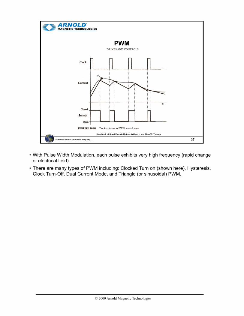
• With Pulse Width Modulation, each pulse exhibits very high frequency (rapid change of electrical field).
• There are many types of PWM including: Clocked Turn on (shown here), Hysteresis, Clock Turn-Off, Dual Current Mode, and Triangle (or sinusoidal) PWM.
© 2009 Arnold Magnetic Technologies
38Our world touches your world every day…
Induct
ion, B
(G
auss)
1: Hysteresis Curve
Applied Field, H (Oersted)
B saturation
B remanance
Hccoercivity
Material Resistivity5:
Magnetostriction4:
Laminations3:
Eddy Current2:
Hysteresis1:
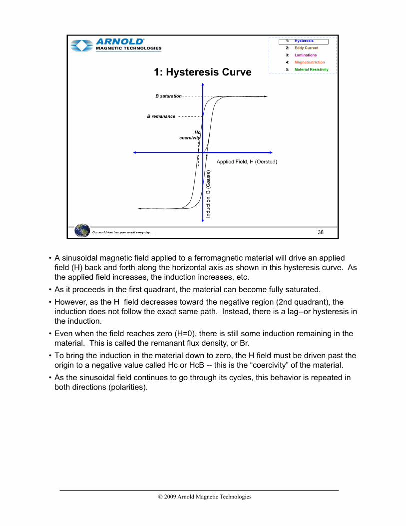
• A sinusoidal magnetic field applied to a ferromagnetic material will drive an applied field (H) back and forth along the horizontal axis as shown in this hysteresis curve. As the applied field increases, the induction increases, etc.
• As it proceeds in the first quadrant, the material can become fully saturated.
• However, as the H field decreases toward the negative region (2nd quadrant), the induction does not follow the exact same path. Instead, there is a lag--or hysteresis in the induction.
• Even when the field reaches zero (H=0), there is still some induction remaining in the material. This is called the remanant flux density, or Br.
• To bring the induction in the material down to zero, the H field must be driven past the origin to a negative value called Hc or HcB -- this is the “coercivity” of the material.
• As the sinusoidal field continues to go through its cycles, this behavior is repeated in both directions (polarities).

© 2009 Arnold Magnetic Technologies
39Our world touches your world every day…
1: Hysteresis Loss
Applied Field, H (Oersted)
Induct
ion, B
(G
auss
)
Bsaturation
Bremanance
Hc
• One implied property from these hysteresis curves is that there is significant energy absorption, represented by the area inside the hysteresis curve.
• In soft magnetic applications, this energy absorption manifests itself as “hysteresis loss”.
• The hysteresis loss is the energy absorbed by the material as it being magnetized in one direction, magnetized in the reverse direction, and re-magnetized in the original direction.

© 2009 Arnold Magnetic Technologies
40Our world touches your world every day…
1: Hysteresis Curve - Minor Loops
8000
6000
4000
2000
0
-2000
-4000
-6000
8000
-20 -12 -4 0 4 12 20
FIELD STRENGTH, H (Oe)
IND
UC
TIO
N, B
(G
AU
SS
)
Matches DC Mag curve
• In a PM motor, the material is not likely to be driven to saturation except at the pole tips. As a result, much of the material will be using “minor” loop properties.
• This is a series of super-imposed minor hysteresis loops. It can be clearly seen that the induction response differs greatly depending upon the level of applied field (H).
• The energy loss will be equal to the area within the specific minor loop experienced by each part of the lamination.
• Since not all the material will see the same externally applied field, there will be unequal energy loss from place to place within the lamination structure.
© 2009 Arnold Magnetic Technologies
41Our world touches your world every day…
1: Hysteresis Loss - Frequency Effects
Applied Field, H (Oersted)In
duct
ion, B
(G
auss
)
Low FrequencyHigh Frequency
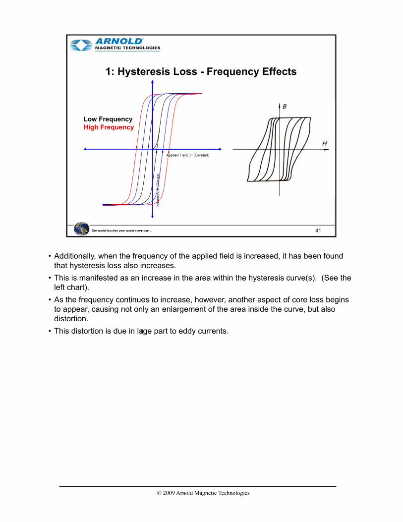
• Additionally, when the frequency of the applied field is increased, it has been found that hysteresis loss also increases.
• This is manifested as an increase in the area within the hysteresis curve(s). (See the left chart).
• As the frequency continues to increase, however, another aspect of core loss begins to appear, causing not only an enlargement of the area inside the curve, but also distortion.
• This distortion is due in large part to eddy currents.

© 2009 Arnold Magnetic Technologies
42Our world touches your world every day…
2: Eddy Current Loss
NS
Material Resistivity5:
Magnetostriction4:
Laminations3:
Eddy Current2:
Hysteresis1:
hyperphysics.phy-astr.gsu.edu/hphys.html
• As the magnetic field alternates through a conductor, eddy currents are created in the material. These are localized currents, flowing in a closed path within the lamination. In accordance with Lenz’s law, these currents oppose change in the field that is inducing the eddy currents.
• The creation of these currents requires energy, and therefore is a source of energy loss.
• Eddy current loss is in addition to hysteresis loss.
• It should be noted that eddy currents can occur in any conductive material including non-magnetic copper and aluminum. In fact, it can be shown that eddy currents in a non-magnetic conductor can exert significant braking effect relative to a moving magnet (forming the basis for hysteresis brakes, clutches and drives).
• The key point here is that eddy currents are caused either by a permanent magnet moving in relation to the conductive material or by a changing electromagnetic field generated by current flow in a conductor.

© 2009 Arnold Magnetic Technologies
43Our world touches your world every day…
2: Eddy Current Skin Depth
Ferromagnetism, R.M. Bozorth, p.771
By definition then, when s = 1/e, H ~ 36.8% of the surface field, HO
• As frequency increases, eddy currents cannot penetrate as far into the conductive material. This is known as skin effect.
• Bozorth shows the skin depth, “s”, as a function of
f = frequency in Hz
Mu = permeability
Rho = resistivity in ohm•cm

© 2009 Arnold Magnetic Technologies
44Our world touches your world every day…
2: Eddy Current Skin Depth
Percent of Skin Depth, "s", at 50 Hz
0%
10%
20%
30%
40%
50%
60%
70%
80%
90%
100%
0 500 1,000 1,500 2,000 2,500 3,000 3,500 4,000 4,500 5,000
Frequency, Hz
• As frequency increases eddy currents penetrate to a far lesser extent.
• Penetration depth decreases very rapidly when (switching) frequency increases above 50 Hz, reaching at 400 Hz just ~35% of the penetration depth at 50 Hz .

© 2009 Arnold Magnetic Technologies
45Our world touches your world every day…
2: Eddy Current Loss
NS
• Since eddy currents are caused by induced voltage in conductive material, dividing the material into insulated layers breaks up the induced voltage lowering eddy current loss dramatically. That is: the sum of the losses per layer is much less than the loss for the undivided material. Induced voltage is proportional to frequency so there is greater benefit from more and thinner layers as the frequency increases.
• In practical devices then, eddy current loss can be lowered by reducing the thickness of the laminations and including an insulating coating between the laminations.
• In fact, coating technology plays a major role in the ability to use soft magnetic materials at the high frequencies becoming common today.
• A second method to achieve reduction in eddy current loss is use of materials with relatively high resistivity.
• Incidentally, this is why ferrite cores, being a ceramic insulator, are used in very high frequency transformer/inductor applications. However, their saturation magnetization is so low that they are not considered useful for motors and generators.
• Another family of materials, SMC’s (Soft Magnetic Composites) are of interest for frequencies above those where thin gauge Si-Fe is useful.

© 2009 Arnold Magnetic Technologies
46Our world touches your world every day…
2: Si-Fe Resistivity
K1 = Magnetocrystalline Anisotropy constantRho = Electrical Resistivity
Js = Saturation MagnetizationSigma = Yield Stress
Measurement and Characterization of Magnetic Materials, Fausto Fiorillo, p.39
or micro-ohm•cm
• The electrical resistivity of 3% Silicon-iron is approximately 48 micro-ohm• cm.
• This is about five times higher than low carbon steel.
• Saturation magnetization is reduced by the presence of silicon, dropping by about 6% with 3% Si. But since most of the lamination is not driven to saturation in PM motors, this small drop has minimal affect on normal use.

© 2009 Arnold Magnetic Technologies
47Our world touches your world every day…
2: Core Loss MechanismsSilicon Steel Core Loss
Measurement and Characterization of Magnetic Materials, Fausto Fiorillo, p.31
W = Wh + Wcl + Wexc Where Classical Loss is
• This chart shows the actual measured core loss of a silicon iron lamination structure with loss components.
• Note that in reference literature, the Hysteresis Loss (Wh) is close to constant with frequency. The distortion of the hysteresis loop and the resulting shifts in loss may be ascribed to the eddy currents.
• The Classical Loss (Wcl, including eddy current loss) is shown as proportional to frequency.
• The remaining loss is complex in mechanism, and is often referred to as: Anomalous Loss, Residual Loss or Excess Loss. It has not yet been satisfactorily explained though efforts are underway to do so such as the efforts at Clarkson University under the direction of Professor Prag Pillay.
• Lamination thickness in this example is 0.29 mm under sinusoidal time dependence of polarization.
Delta = density
d = lamination thickness
Sigma = conductivity
Jp = Peak Polarization
f = frequency

© 2009 Arnold Magnetic Technologies
48Our world touches your world every day…
3: Stacking Factor
75%
80%
85%
90%
95%
100%
0.000 0.010 0.020 0.030 0.040 0.050 0.060 0.070
Stacking Factor
Stacking Factor is limited by:
• Strip Flatness
• Wedge
• Coating Thickness
• # of layersCoating as a % of Lamination Thickness
0%
2%
4%
6%
8%
10%
12%
14%
0.000 0.005 0.010 0.015 0.020 0.025 0.030
Nominal Lamination Thickness, inches
Co
ati
ng
as a
% o
f T
hic
kn
ess
Nominal coating thicknessof 0.000075” per surface
Material Resistivity5:
Magnetostriction4:
Laminations3:
Eddy Current2:
Hysteresis1:
Relevant StandardASTM A 719/A 719M – 02Standard Test Method for Lamination Factor of Magnetic Materials
0.005” 0.014”
• We’ve seen that reducing lamination thickness can reduce core loss due to eddy currents. However, there are several drawbacks that provide practical limits to how thin the laminations may be economically made and used.
1. COATING: First, the coating, although very thin (between 50 and 120 millionths of an inch), separates the laminations. We see in the chart to the right that with 0.005” laminations that a typical coating represents 3% of the total lamination thickness. Were there no other effects, the stacking factor could be a maximum of only 97%.
2. PHYSICAL IMPERFECTIONS: Secondly, laminations are not physically perfect. They sufferfrom wedge and waffling, both contribute to irregular gaps between layers and the actual achievable stacking factor is approximately as shown in the left chart.
3. QUANTITY HANDLED: Another issue is that of requirements for punching and stacking larger numbers of laminations to make up the total stack height.
4. PUNCH DIFFICULTY: A 4 th issue is that punching of steel becomes more difficult as the laminations become thinner. Thicknesses to 0.001” are possible, but punch difficulty increases dramatically below a lamination thickness of 0.005”. At these thin gauges punching is actually a controlled tear. Punch tooling has to be of the highest quality and maintained rigorously.
• The use of thin gauge, therefore, depends upon a balance of performance with cost and technical feasibility. Switching frequencies of 400 Hz and higher or the requirement for extremely low core loss make thin gauge NGOES a requisite.

© 2009 Arnold Magnetic Technologies
49Our world touches your world every day…
4: Magnetostriction
Li, Initial Length �L, length change in presence of magnetic field
• Magnetostriction: Dimensional changes due to applied field
• Common in many soft magnetic materials
• Can contribute to core loss
Material Resistivity5:
Magnetostriction4:
Laminations3:
Eddy Current2:
Hysteresis1:
• Ferromagnetic materials experience minor dimensional change when placed in a magnetic field. This effect is called “magnetostriction.”
• The magnitude of these physical changes (�L / Li) are small, typically a few parts per million.
• These dimensional changes absorb energy and contribute to the total core loss.
• Magnetostriction can manifest itself as audible noise, e.g. “transformer hum.”
© 2009 Arnold Magnetic Technologies
50Our world touches your world every day…
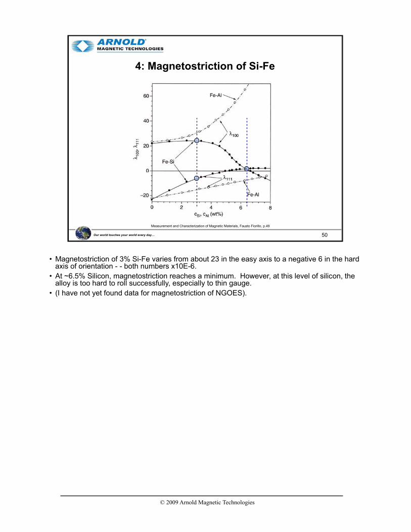
4: Magnetostriction of Si-Fe
Measurement and Characterization of Magnetic Materials, Fausto Fiorillo, p.49
• Magnetostriction of 3% Si-Fe varies from about 23 in the easy axis to a negative 6 in the hard axis of orientation - - both numbers x10E-6.
• At ~6.5% Silicon, magnetostriction reaches a minimum. However, at this level of silicon, the alloy is too hard to roll successfully, especially to thin gauge.
• (I have not yet found data for magnetostriction of NGOES).

© 2009 Arnold Magnetic Technologies
51Our world touches your world every day…
5: Material Options & Applications
100 Hz
1 kHz
10 kHz
100 kHz
1 MHz
10 MHz
100 MHz
1 GHz
10GHz
Soft Magnetic MaterialsSoft Magnetic Materials ApplicationsApplications
Cost Per Unit Volume
Si Laminations
Iron Powder
Sendust
Si Tape
50% Ni-Fe Powder
Amorphous
Ni Tape
MPP
Fre
qu
en
cy
Nanocrystalline
Cobalt Tape
Ni-Zn Ferrite
Mn-Zn Ferrite
IronDC Ni Laminations
Microwave Circulators, Broadband Transformers, Radar, Communication Transceivers
Distribution, Welding and Ferroresonant Transformers, Electromagnetic Ballasts, Power Inductors, Motors, Generators, Relays
Aircraft (400hz) Power Transformers, Resonant Inductors for lighting, Industrial Power Control, Current Transformers
Audio frequency Transformers, Instrumentation Transformers, Telephone Line Interface Transf ormers for Modems, Speaker Crossover Networks
Railroad Signaling, Audio Transformers, Medical CT & NMR Scanners, Switchmode Power Transformers, Filters, Chokes, UPS , Industrial Control Transformers, Electronic Ballast
EMI & RFI Filters, Broadband Baluns & Transformers for DSL & Modems, ISDN, Flyback Transformers for Televisions & Computer Monitors, Switchmode Power Supplies, Regulators for Battery Powered Devices
Ferrite Antenna Rods, Impedence Matching Transformers, EMI Supression Beads, Cable Shields, Filter Inductors, RF Power Amplifiers, Wireless Communication Equipment
Material Resistivity5:
Magnetostriction4:
Laminations3:
Eddy Current2:
Hysteresis1:
• This chart offers a comparison of soft magnetic materials as a function of cost and usable frequency range.
• Maximum use frequency depends on the operating flux density so the chart should be viewed as a general guide.
• Increasing cost per unit volume is shown from left to right. Performance improvements from a more expensive core material can provide for lower overall system cost.
• Silicon steel is used so widely because itr epresents a good comb ination of cost and performance.

© 2009 Arnold Magnetic Technologies
52Our world touches your world every day…
5: Comparing Properties
Relative Permeability
10 102 103 104 105 106
Bs (
Satu
rati
on
In
du
cti
on
), k
Gau
ss
0
05
10
15
20
25
30
Co-Fe
FeSi-Fe
36-50% Ni-Fe
Amorphous Alloys
75% Ni-Fe
Fe Powder Cores
Ni-Fe Powder Cores
Soft Ferrites
Co-Fe: Outstanding performance but at a high price
Si-Fe: Excellent performance at a reasonable price
• This slide plots permeability versus saturation induction for common soft magnetic materials. Both properties are usually desirable, so the best performing material shown would be the iron-cobalt alloys. While they are expensive, they are among of the best performers.
• Only slightly lower in performance is the much less costly Si-Fe material.
• Although iron can have very high permeability and high magnetic saturation, it must be pure, annealed properly and is still susceptible to hardening from mechanical working and aging.
© 2009 Arnold Magnetic Technologies
53Our world touches your world every day…
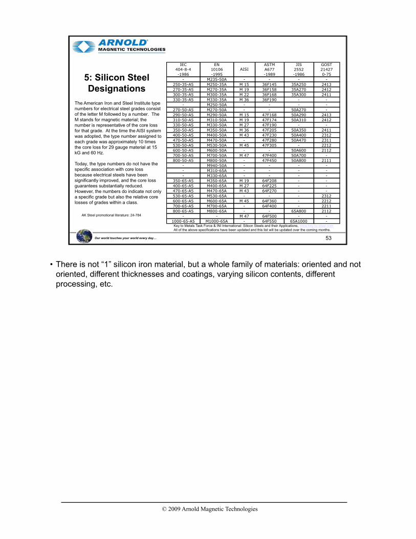
5: Silicon Steel Designations
Key to Metals Task Force & INI International: Silicon Steels and their Applications, www.key-to-steel.comAll of the above specifications have been updated and this list will be updated over the coming months.
IEC EN ASTM JIS GOST404-8-4 10106 A677 2552 21427
-1986 -1995 -1989 -1986 0-75
- M235-50A - - - -
250-35-A5 M250-35A M 15 36F145 35A250 2413
270-35-A5 M270-35A M 19 36F158 35A270 2412
300-35-A5 M300-35A M 22 36F168 35A300 2411
330-35-A5 M330-35A M 36 36F190 - -
- M250-50A - - - -
270-50-A5 M270-50A - - 50A270 -
290-50-A5 M290-50A M 15 47F168 50A290 2413
310-50-A5 M310-50A M 19 47F174 50A310 2412
330-50-A5 M330-50A M 27 47F190 - -
350-50-A5 M350-50A M 36 47F205 50A350 2411
400-50-A5 M400-50A M 43 47F230 50A400 2312
470-50-A5 M470-50A - 47F280 50A470 2311
530-50-A5 M530-50A M 45 47F305 - 2212
600-50-A5 M600-50A - - 50A600 2112
700-50-A5 M700-50A M 47 47F400 50A700 -
800-50-A5 M800-50A - 47F450 50A800 2111
- M940-50A - - - -
- M310-65A - - - -
- M330-65A - - - -
350-65-A5 M350-65A M 19 64F208 - -
400-65-A5 M400-65A M 27 64F225 - -
470-65-A5 M470-65A M 43 64F270 - -
530-65-A5 M530-65A - - - 2312
600-65-A5 M600-65A M 45 64F360 - 2212
700-65-A5 M700-65A - 64F400 - 2211
800-65-A5 M800-65A - - 65A800 2112
- - M 47 64F500 - -
1000-65-A5 M1000-65A - 64F550 65A1000 -
AISI
The American Iron and Steel Institute type numbers for electrical steel grades consist of the letter M followed by a number. The M stands for magnetic material; the number is representative of the core loss for that grade. At the time the AISI system was adopted, the type number assigned to each grade was approximately 10 times the core loss for 29 gauge material at 15 kG and 60 Hz.
Today, the type numbers do not have the specific association with core loss because electrical steels have been significantly improved, and the core loss guarantees substantially reduced. However, the numbers do indicate not only a specific grade but also the relative core losses of grades within a class.
AK Steel promotional literature: 24-784
• There is not “1” silicon iron material, but a whole family of materials: oriented and not oriented, different thicknesses and coatings, varying silicon contents, different processing, etc.

© 2009 Arnold Magnetic Technologies
54Our world touches your world every day…
Agenda
• Introduction
• GOES versus NGOES
• Manufacturing Process
• Motor & Transformer Efficiency
• Loss Factors
• NGO Thin Gauge (Arnon)
• Thin gauge Si-Fe (<=0.007”, e.g. Arnon) is particularly useful for high frequency operation to reduce eddy current loss.
• Oriented product is commonly used in high frequency or burst pulse transformer applications where the benefit of directional properties can be utilized.
• In motors, generators and rotating machinery in general, non-oriented Si-Fe is preferred since the field intersects the material at varying angles and performance benefits from material isotropy.

© 2009 Arnold Magnetic Technologies
55Our world touches your world every day…
Applications
• Silicon-Steel– Reduced eddy current losses due to material resistivity
• Thin Gauge (<0.014”)– Reduced eddy currents at frequencies of 400 Hz and higher
• Non-Grain Oriented– Where the direction of magnetic flux is changing
– Less sensitive to strain than grain oriented
Low loss Arnon materials, at 0.005 and 0.007” thicknesses, are especially useful in totally enclosed motor designs and large
devices where heat cannot be easily removed.
• Three good reasons to use Arnon are:
- Silicon steel has higher inherent resistivity
- Thin gauge reduces eddy current loss
- Non-oriented magnetic properties improve performance in rotating machinery
• Arnon HcB is less than 0.6 Oersteds, 8 to 15% less than competitive NGOES, resulting in lower hysteresis core loss. (Comparative measurements on same equipment during the same measurement session). Total loss is reported to be as much as 50% lower than for competitive thin gauge materials.
• This lower HcB results from very specific processing conditions during rolling and annealing.

© 2009 Arnold Magnetic Technologies
56Our world touches your world every day…
DC Measurements
• Recent measurements or Arnon 5 and 7 mil product versus other commercial products is shown in these DC hysteresis loops.
• In addition to the different loop shapes, Arnon has consistently lower values for HcB(18% lower for Arnon 5 versus competitive materials).
© 2009 Arnold Magnetic Technologies
57Our world touches your world every day…
Hysteresis Curve - Minor Loops
8000
6000
4000
2000
0
-2000
-4000
-6000
8000
-20 -12 -4 0 4 12 20
FIELD STRENGTH, H (Oe)
IND
UC
TIO
N, B
(G
AU
SS
)
Matches DC Mag curve
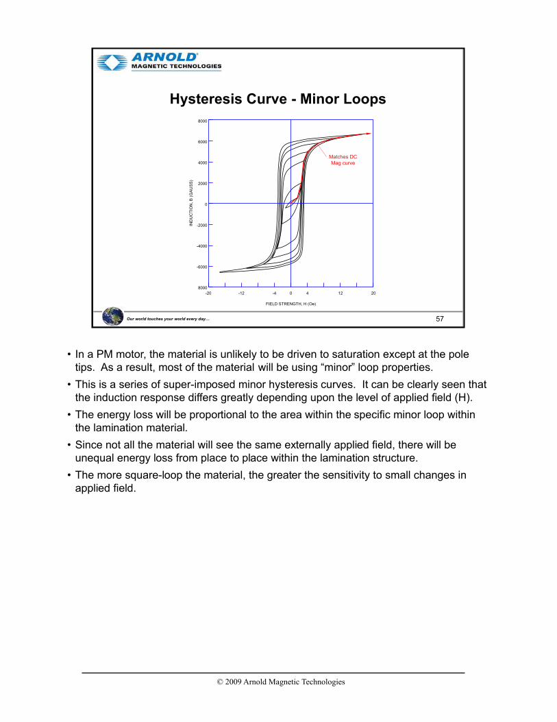
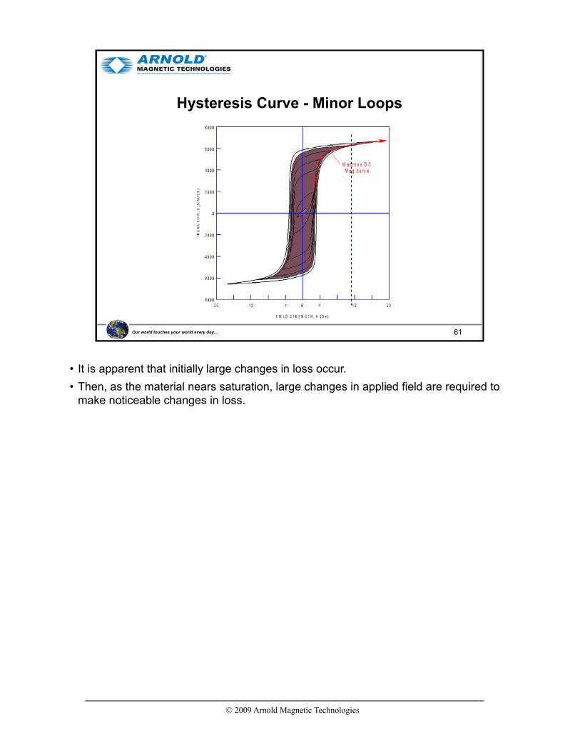
• In a PM motor, the material is unlikely to be driven to saturation except at the pole tips. As a result, most of the material will be using “minor” loop properties.
• This is a series of super-imposed minor hysteresis curves. It can be clearly seen that the induction response differs greatly depending upon the level of applied field (H).
• The energy loss will be proportional to the area within the specific minor loop within the lamination material.
• Since not all the material will see the same externally applied field, there will be unequal energy loss from place to place within the lamination structure.
• The more square-loop the material, the greater the sensitivity to small changes in applied field.
© 2009 Arnold Magnetic Technologies
58Our world touches your world every day…
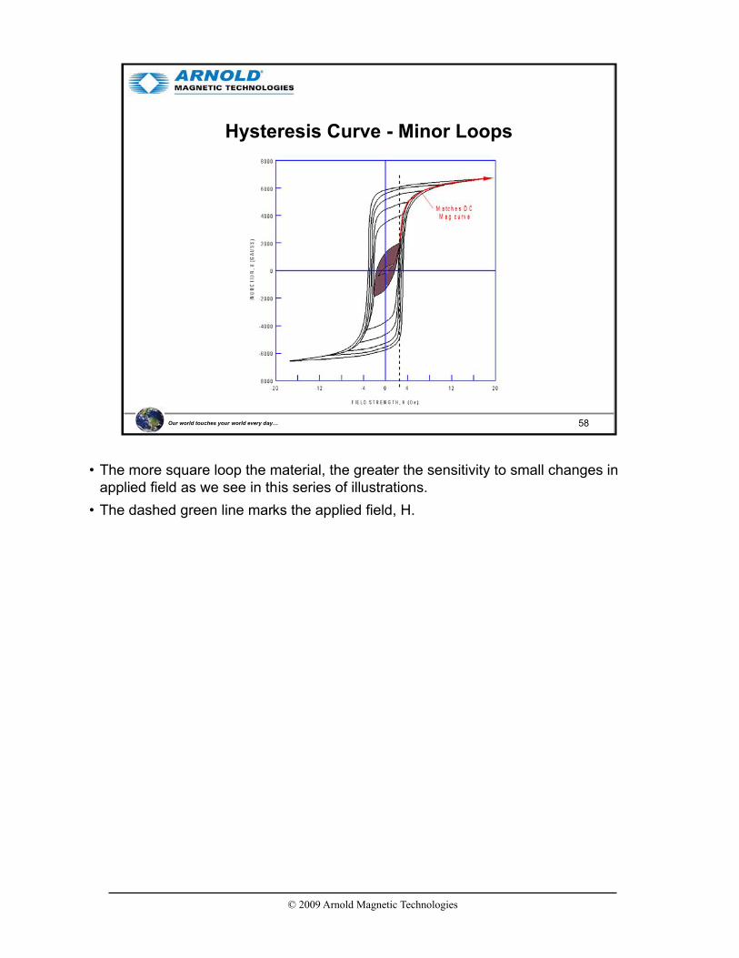
Hysteresis Curve - Minor Loops
• The more square loop the material, the greater the sensitivity to small changes in applied field as we see in this series of illustrations.
• The dashed green line marks the applied field, H.

© 2009 Arnold Magnetic Technologies
59Our world touches your world every day…
Hysteresis Curve - Minor Loops

© 2009 Arnold Magnetic Technologies
60Our world touches your world every day…
Hysteresis Curve - Minor Loops
© 2009 Arnold Magnetic Technologies
61Our world touches your world every day…
Hysteresis Curve - Minor Loops
• It is apparent that initially large changes in loss occur.
• Then, as the material nears saturation, large changes in applied field are required to make noticeable changes in loss.
© 2009 Arnold Magnetic Technologies
62Our world touches your world every day…
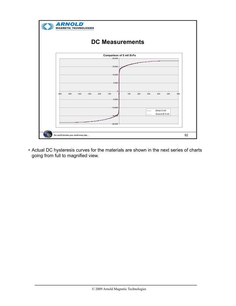
DC Measurements
Comparison of 5 mil Si-Fe
-20,000
-15,000
-10,000
-5,000
0
5,000
10,000
15,000
20,000
-600 -500 -400 -300 -200 -100 0 100 200 300 400 500 600
Arnon 5 mil
Source B 5 mil
• Actual DC hysteresis curves for the materials are shown in the next series of charts going from full to magnified view.

© 2009 Arnold Magnetic Technologies
63Our world touches your world every day…
DC Measurements
Comparison of 5 mil Si-Fe
-15,000
-10,000
-5,000
0
5,000
10,000
15,000
-20 -15 -10 -5 0 5 10 15 20
Arnon 5 mil
Source B 5 mil
• In this second chart the difference between Arnon and the competitive material is clearly evident.

© 2009 Arnold Magnetic Technologies
64Our world touches your world every day…
DC Measurements
Comparison of 5 mil Si-Fe
0
5,000
10,000
15,000
-1 0 1 2 3
Arnon 5 mil
Source B 5 mil
• What we see is the difference in “B” achieved at any level of “H”.
• Specifically, The applied field to drive the competitor material to B=10,000 only drives the Arnon to 9200 Gauss.
• At the pole tips both materials will be driven to saturation. However, at locations of lower applied field, the Arnon will not be driven to as high a “B.”
• While we could integrate within the curves to calculate the difference in hysteresis loss, it is easier to simply measure it.
© 2009 Arnold Magnetic Technologies
65Our world touches your world every day…
Arnold 0.005" Ring, 9294MPS08
100
1,000
10,000
100,000
0.01 0.1 1 10 100 1000 10000
Core Loss (W/lb)
B (
G)
60 Hz120 Hz200 Hz400 Hz1000 Hz2000 Hz3000 Hz4000 Hz5000 Hz10,000 Hz20,000 Hz
Core Lossas a Function of Frequency
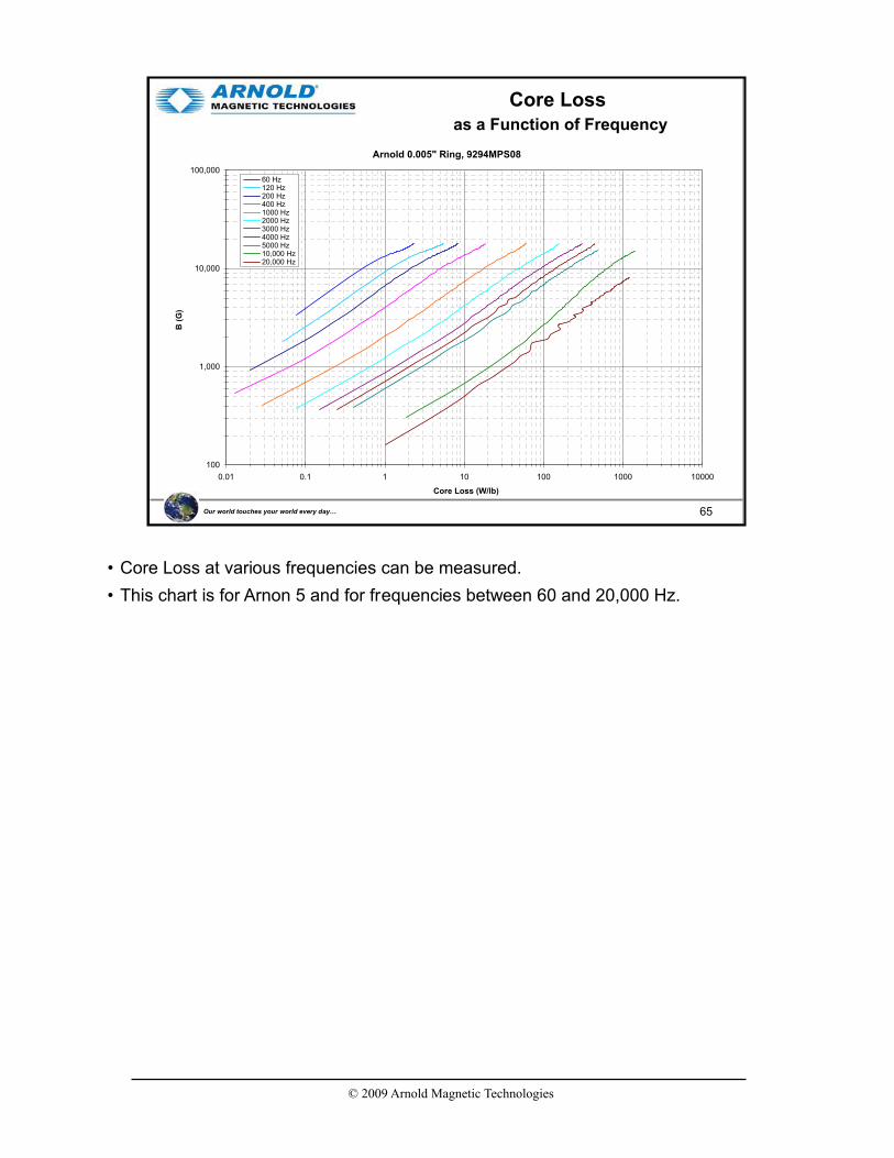
• Core Loss at various frequencies can be measured.
• This chart is for Arnon 5 and for frequencies between 60 and 20,000 Hz.

© 2009 Arnold Magnetic Technologies
66Our world touches your world every day…
Arnold 0.007" Ring, 9295MPS08
100
1,000
10,000
100,000
0.01 0.1 1 10 100 1000 10000
Core Loss (W/lb)
B (
G)
60 Hz120 Hz200 Hz400 Hz1000 Hz2000 Hz3000 Hz4000 Hz5000 Hz10000 Hz20000 Hz
Core Lossas a Function of Frequency
• This presents the same data for Arnon 7.

© 2009 Arnold Magnetic Technologies
67Our world touches your world every day…
Comparison of Arnon and Source "B" 5 mil Si-Fe
1,000
10,000
100,000
0.01 0.10 1.00 10.00 100.00
Core Loss (W/lb)
B (
G)
Arnon, 5 mil, 60 Hz
Source B, 5 mil, 60 Hz
Arnon, 5 mil, 400 Hz
Source B, 5 mil, 400 Hz
Core LossComparison of 5 mil by Product Source
• A comparison between Arnon 5 and the source B 5 mil material is shown here.

© 2009 Arnold Magnetic Technologies
68Our world touches your world every day…
Comparison of 5 mil Si-Fe
0
5,000
10,000
15,000
-1 0 1 2 3
Arnon 5 mil
Source B 5 mil
Comparison of 5 mil Si-Feby Achieved Induction “B”
• By referring to this chart we see that when Source B material is driven to 10,000 Gauss, that the Arnon is driven to 9300.

© 2009 Arnold Magnetic Technologies
69Our world touches your world every day…
Comparative Core Loss, 5 mil Si-Fe
• By comparing the core loss at the level of “B” achieved by the applied field in the device, we see a core loss difference of 0.45 (Arnon) versus 0.68 (Source B).
• Source B is 50 % higher than the Arnon when driven by the same “H” field.
• This confirms anecdotal customer information on the relative performance.
• It confirms the importance of hysteresis curve shape as well as saturation magnetization.

© 2009 Arnold Magnetic Technologies
70Our world touches your world every day…
Arnon 5 and 7 Core LossNon-Grain Oriented, 5 and 7 mil Si-Fe
0
10
20
30
40
50
60
70
0 500 1000 1500 2000
Frequency
Co
re L
os
s,
W/p
ou
nd
7 mil
5 mil
8 pole, 10000 rpm
8 pole, 14000 rpm
8 pole, 5400 rpm
4 pole, 3600 rpm
Arnon 5is 24% lower
• Below 400 Hz, core loss for both Arnon 5 and Arnon 7 are similarly low.
• Above 400 Hz, Arnon becomes increasingly more advantageous.
• Several example frequencies are shown here emphasizing that higher RPM and greater number of poles drives the switching frequency higher.
© 2009 Arnold Magnetic Technologies
71Our world touches your world every day…
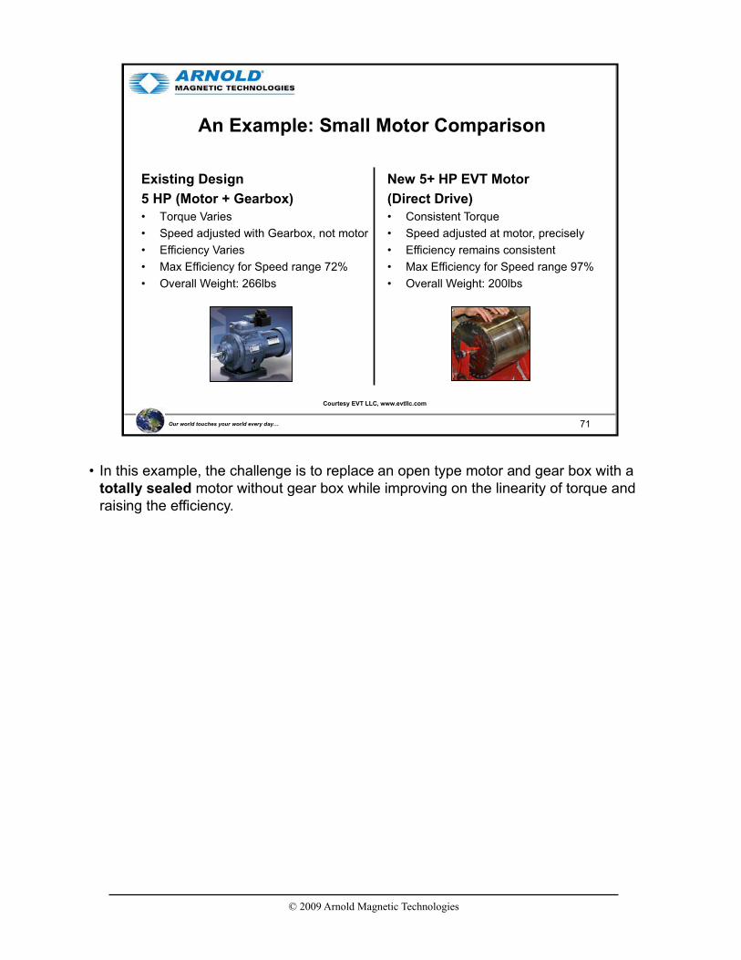
An Example: Small Motor Comparison
Existing Design
5 HP (Motor + Gearbox)
• Torque Varies
• Speed adjusted with Gearbox, not motor
• Efficiency Varies
• Max Efficiency for Speed range 72%
• Overall Weight: 266lbs
New 5+ HP EVT Motor
(Direct Drive)
• Consistent Torque
• Speed adjusted at motor, precisely
• Efficiency remains consistent
• Max Efficiency for Speed range 97%
• Overall Weight: 200lbs
Courtesy EVT LLC, www.evtllc.com
• In this example, the challenge is to replace an open type motor and gear box with a totally sealed motor without gear box while improving on the linearity of torque and raising the efficiency.
© 2009 Arnold Magnetic Technologies
72Our world touches your world every day…
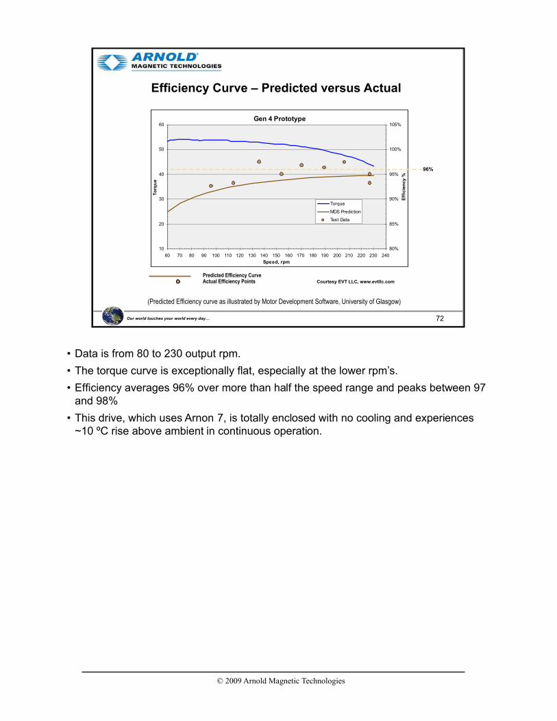
Efficiency Curve – Predicted versus Actual
(Predicted Efficiency curve as illustrated by Motor Development Software, University of Glasgow)
Predicted Efficiency CurveActual Efficiency Points Courtesy EVT LLC, www.evtllc.com
96%
Gen 4 Prototype
10
20
30
40
50
60
60 70 80 90 100 110 120 130 140 150 160 170 180 190 200 210 220 230 240
Speed, rpm
To
rqu
e
80%
85%
90%
95%
100%
105%
Effi
cie
ncy %
Torque
MDS Prediction
Test Data
• Data is from 80 to 230 output rpm.
• The torque curve is exceptionally flat, especially at the lower rpm’s.
• Efficiency averages 96% over more than half the speed range and peaks between 97 and 98%
• This drive, which uses Arnon 7, is totally enclosed with no cooling and experiences ~10 ºC rise above ambient in continuous operation.

© 2009 Arnold Magnetic Technologies
73Our world touches your world every day…
Very Thin Gauge Si-Fe (Grain-Oriented)
Frequency
RecommendedThickness
Approximate Inductionfor 300 mW/cc
18 W/lb, 40 W/kg*
400 Hz 4 mil or 6 mil 15,000 G*1 kHz 4 mil or 6 mil 10,000 G2 kHz 2 mil 6,000 G5 kHz 1 mil 3,000 G
Table 1. Recommended Grain Oriented Silicon Steel Thicknesses for Various Operating Frequencies
* For reference only. Based on Arnold C-core data records. (Arnold no
longer manufactures C-cores). At 400 Hz, magnetizing current limits the
maximum flux density.
Pulse WidthRecommended
ThicknessPulses per Second
2 to 1000microseconds
4 mil or 6 mil(D-U, U-I, L-LLaminations)
to 1000
0.25 to 2microseconds
1 mil or 2 mil(C-core)
to 1000
Table 2. Recommended Grain Oriented Silicon Steel Thicknesses for High-Power Pulse Operating Conditions*
* For reference only. Based on Arnold C-core data records. (Arnold no
longer manufactures C-cores). At 400 Hz, magnetizing current limits the
maximum flux density.
NGOES is used for rotating machinery.GOES (Grain oriented electrical steel) is used in transformers and inductors.
• Arnold also produces grain oriented Si-Fe at 1, 2, 4, and 6 mil, primarily for use in laminated and wound high frequency transformers and chokes.
• Although Grain-Oriented is not normally used for rotating machinery, at least one recent design incorporates this material in a segmented stator design - - segmented to allow alignment of the laminations more closely to the applied field.

© 2009 Arnold Magnetic Technologies
74Our world touches your world every day…
Summary
• Higher efficiency is being driven by both economic and political forces
• Si-Fe offers performance improvements over steel and cost reduction over Co-Fe
• Thin gage Si-Fe provides efficiency improvements with thinner gage increasingly advantageous with higher frequencies
• The magnetic loop shape of Arnon provides substantially reduced hysteresis loss in rotating machinery.
© 2009 Arnold Magnetic Technologies
75Our world touches your world every day…
References
• Ferromagnetism, Richard M. Bozorth, IEEE Press, 1993
• Measurement and Characterization of Magnetic Materials, Fausto Fiorillo, Elsevier Academic Press, 2004
• Handbook of Small Electric Motors, William H. Yeadon and Alan W. Yeadon, McGraw-Hill, 2001
• Handbook of Electromagnetic Materials, Perambur S. Neelakanta, CRC Press, 1995
• Electrical Materials Handbook, Allegheny Ludlum Steel Corp., 1961
• Handbook of transformer Design & Applications, William M. Flanagan, McGraw-Hill, 1992
• Applications of Magnetism, J.K. Watson, Storter Printing, 1985
• Proto Laminations Website (www.protolam.com)
• Lamination Steels CD-ROM, EMERF
• Silicon Steels and Their Applications (www.key-to-steel.com/DE/DE/Articles/Art101.htm)
• Hyperphysics (http://hyperphysics.phy-astr.gsu.edu/hbase/HFrame.html)
• Wikipedia (www.wikipedia.org)
• All of these were useful, but the three in dark blue were excellent.

© 2009 Arnold Magnetic Technologies
76Our world touches your world every day…
Thank you !
FEA from Permanent Magnet Motor Technology: Design and Applications, Jacek Gieras and Mitchell Wing, p.200


![On Arnold’s variational principles in fluid mechanicski502/review6.pdf · On Arnold’s variational principles in fluid mechanics V.A.Vladimirov ... (see Arnold [1965a, 1966a],](https://static.fdocuments.in/doc/165x107/5b1f1a957f8b9af1328c41a0/on-arnolds-variational-principles-in-uid-mechanics-ki502-on-arnolds.jpg)

