Energy Recovery Rooftop System - bosch-climate.us Recovery Rooftop System COMMERCIAL ... Over 30...
12
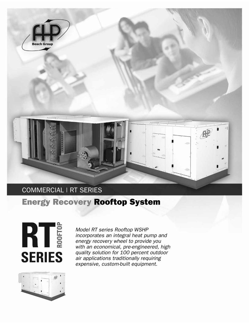
Energy Recovery Rooftop System COMMERCIAL | RT SERIES Model RT series Rooftop WSHP incorporates an integral heat pump and energy recovery wheel to provide you with an economical, pre-engineered, high quality solution for 100 percent outdoor air applications traditionally requiring expensive, custom-built equipment.
Transcript of Energy Recovery Rooftop System - bosch-climate.us Recovery Rooftop System COMMERCIAL ... Over 30...
Energy Recovery Rooftop System
COMMERCIAL | RT SERIES
Model RT series Rooftop WSHP incorporates an integral heat pump and energy recovery wheel to provide you with an economical, pre-engineered, high quality solution for 100 percent outdoor air applications traditionally requiring expensive, custom-built equipment.

2 | RT SERIES
970-457
Building design specifications require a certain amount of fresh air be delivered into the building. Introducing untreated air has the potential for creating uncontrolled conditions in the space resulting in conditions of high humidity with the resultant formation of mold which not only can create a sick building syndrome but can be prohibitively expensive to rectify. Without a heat recovery device energy in the exhaust air is lost increasing the operating cost significantly.
The RT series combines the benefits of the total energy wheel with supplemental heating and cooling by the water source heat pump. The result is a product that is specifically designed to process 100% outdoor air to desired supply conditions.
Four cabinet sizes provide air flow capacities from 1,000 cfm to 10,000 cfm with external static pressures up to 2.5 in. wg.
FHP RT series unit’s built-in energy recovery wheel can recover 75% of the energy normally wasted through the exhausted air which is then used to condition the incoming supply air. This means savings of 3 to 4 tons of cooling and 50 – 60 MBH of heating for every 1,000 cfm of outdoor air depending on local climatic conditions.
Over 30 years of heat pump design experience lies behind the factory installed heat pump providing peace of mind and the knowledge that you will have a matched system. It also eliminates the cost and liability associated with field piping, charging and wiring by the contractor. A computer selection program simplifies unit selection and provides you several options to meet your specific requirements.
All this without having to pay a custom unit premium.
The result, reduced installation costs and increased energy savings over the life of the unit.
Cooling1.Outdoor air enters RT unit
2.The energy recovery wheel cools and dehumidifies outdoor air using energy from the exhaust airstream. Load is reduced by 3 to 4 tons per 1,000 cfm for many climates.
3.The heat pump provides supplemental cooling to further treat the outdoor air to desired supply conditions.
4.Optional reheat available to provide space neutral air.
5. Indoor space conditions
Energy Recovery Rooftop System

RT SERIES | 3
REV. 08-10
System Benefits •Versatile Application: FHP RT Series are suitable
for diverse applications, for example schools, office buildings, virtually any building requiring ventilation air.
•Humidity Control: Ventilate buildings adequately without losing control of indoor humidity levels. The RT is capable of conditioning summer outdoor air to room design conditions. Also, it helps prevent overly dry winter air that can contribute to respiratory irritation.
•System Design Simplicity: The RT is designed specifically to provide outdoor air to the space at desired conditions. This effectively de-couples the outdoor air load from the building load.
•Load Reduction: The energy wheel saves 3 to 4 tons of cooling and 50-60 MBH of heating for every 1,000 cfm of outdoor air for many climates.
•Reduced Footprint: In a water source heat pump system the interior units can be sized only for the space load. This reduces the size of these units and the required air flow
providing additional energy savings and reduced installation costs for the system.
•Low Maintenance: Servicing is minimal. All components have a well established history of reliable operation.
•ASHRAE 62 Compliance: By assuring that minimum outdoor air volumes are delivered to the room spaces, compliance with the ASHRAE 62 Standard is clearly demonstrated.
Heating1.Outdoor air enters RT unit
2.The energy recovery wheel heats and humidifies winter outdoor air using energy from the exhaust airstream. Heating bills are significantly reduced and overly dry indoor conditions are eliminated.
3.The heat pump provides supplemental heating to further treat the outdoor air to desired supply conditions.
4. Indoor space conditions
4 | RT SERIES
970-457
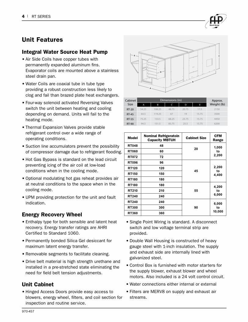
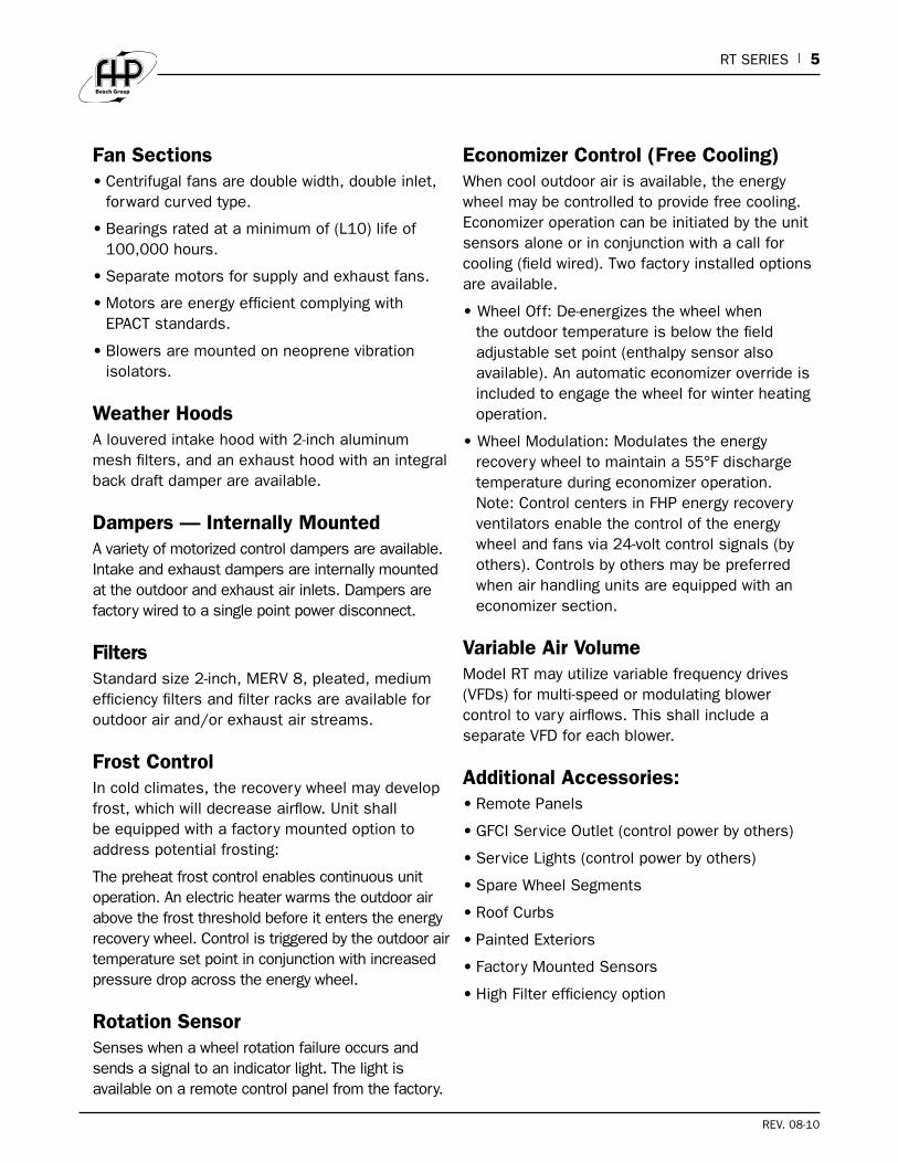
Unit Features
Integral Water Source Heat Pump•AirSideCoilshavecoppertubeswith
permanently expanded aluminum fins. Evaporator coils are mounted above a stainless steel drain pan.
•WaterCoilsarecoaxialtubeintubetypeproviding a robust construction less likely to clog and fail than brazed plate heat exchangers.
•Four-waysolenoidactivatedReversingValvesswitch the unit between heating and cooling depending on demand. Units will fail to the heating mode.
•ThermalExpansionValvesprovidestablerefrigerant control over a wide range of operating conditions.
•Suctionlineaccumulatorspreventthepossibilityof compressor damage due to refrigerant flooding.
•HotGasBypassisstandardontheleadcircuitpreventing icing of the air coil at low-load conditions when in the cooling mode.
•Optionalmodulatinghotgasreheatprovidesairat neutral conditions to the space when in the cooling mode.
•UPMprovidingprotectionfortheunitandfaultindication.
Energy Recovery Wheel•Enthalpytypeforbothsensibleandlatentheat
recovery. Energy transfer ratings are AHRI Certified to Standard 1060.
•PermanentlybondedSilicaGeldesiccantformaximum latent energy transfer.
•Removablesegmentstofacilitatecleaning.
•Drivebeltmaterialishighstrengthurethaneandinstalled in a pre-stretched state eliminating the need for field belt tension adjustments.
Unit Cabinet •HingedAccessDoorsprovideeasyaccessto
blowers, energy wheel, filters, and coil section for inspection and routine service.
•SinglePointWiringisstandard.Adisconnectswitch and low voltage terminal strip are provided.
•DoubleWallHousingisconstructedofheavygauge steel with 1-inch insulation. The supply and exhaust side are internally lined with galvanized steel.
•ControlBoxisfurnishedwithmotorstartersforthe supply blower, exhaust blower and wheel motors. Also included is a 24 volt control circuit.
•Waterconnectionseitherinternalorexternal
•FiltersareMERV8onsupplyandexhaustairstreams.
D
A
E
B
C
Cabinet Size
Dimensions (in) Approx. Weight (lb)A B C D E
RT-20 54.25 108.25 48.75 20.75 17.5 2150
RT-45 64.5 119.25 67 19 15.75 3500
RT-55 75.25 133.5 68.25 23.75 15.75 4450
RT-90 94.5 151.5 83.75 25.5 15.75 6200
Model Nominal Refrigeratoin Capacity MBTUH Cabinet Size CFM
Range
RT048 4820 1,000
to 2,200
RT060 60
RT072 72
RT096 96
452,200
to 4,400
RT120 120
RT150 150
RT180 180
RT180 180
554,200
to 6,000
RT210 210
RT240 240
RT240 240
906,000
to 10,000
RT300 300
RT360 360
RT SERIES | 5
REV. 08-10
Fan Sections•Centrifugalfansaredoublewidth,doubleinlet,
forward curved type.
•Bearingsratedataminimumof(L10)lifeof100,000 hours.
•Separatemotorsforsupplyandexhaustfans.
•MotorsareenergyefficientcomplyingwithEPACT standards.
•Blowersaremountedonneoprenevibrationisolators.
Weather HoodsA louvered intake hood with 2-inch aluminum mesh filters, and an exhaust hood with an integral back draft damper are available.
Dampers — Internally MountedA variety of motorized control dampers are available. Intake and exhaust dampers are internally mounted attheoutdoorandexhaustairinlets.Dampersarefactory wired to a single point power disconnect.
FiltersStandard size 2-inch, MERV 8, pleated, medium efficiency filters and filter racks are available for outdoor air and/or exhaust air streams.
Frost ControlIn cold climates, the recovery wheel may develop frost, which will decrease airflow. Unit shall be equipped with a factory mounted option to address potential frosting:
The preheat frost control enables continuous unit operation. An electric heater warms the outdoor air above the frost threshold before it enters the energy recovery wheel. Control is triggered by the outdoor air temperature set point in conjunction with increased pressure drop across the energy wheel.
Rotation SensorSenses when a wheel rotation failure occurs and sends a signal to an indicator light. The light is available on a remote control panel from the factory.
Economizer Control (Free Cooling)When cool outdoor air is available, the energy wheel may be controlled to provide free cooling. Economizer operation can be initiated by the unit sensors alone or in conjunction with a call for cooling(fieldwired).Twofactoryinstalledoptionsare available.
•WheelOff:De-energizesthewheelwhenthe outdoor temperature is below the field adjustablesetpoint(enthalpysensoralsoavailable).Anautomaticeconomizeroverrideisincluded to engage the wheel for winter heating operation.
•WheelModulation:Modulatestheenergyrecovery wheel to maintain a 55°F discharge temperature during economizer operation. Note: Control centers in FHP energy recovery ventilators enable the control of the energy wheelandfansvia24-voltcontrolsignals(byothers).Controlsbyothersmaybepreferredwhen air handling units are equipped with an economizer section.
Variable Air VolumeModel RT may utilize variable frequency drives (VFDs)formulti-speedormodulatingblowercontrol to vary airflows. This shall include a separateVFDforeachblower.
Additional Accessories:•RemotePanels
•GFCIServiceOutlet(controlpowerbyothers)
•ServiceLights(controlpowerbyothers)
•SpareWheelSegments
•RoofCurbs
•PaintedExteriors
•FactoryMountedSensors
•HighFilterefficiencyoption

6 | RT SERIES
970-457
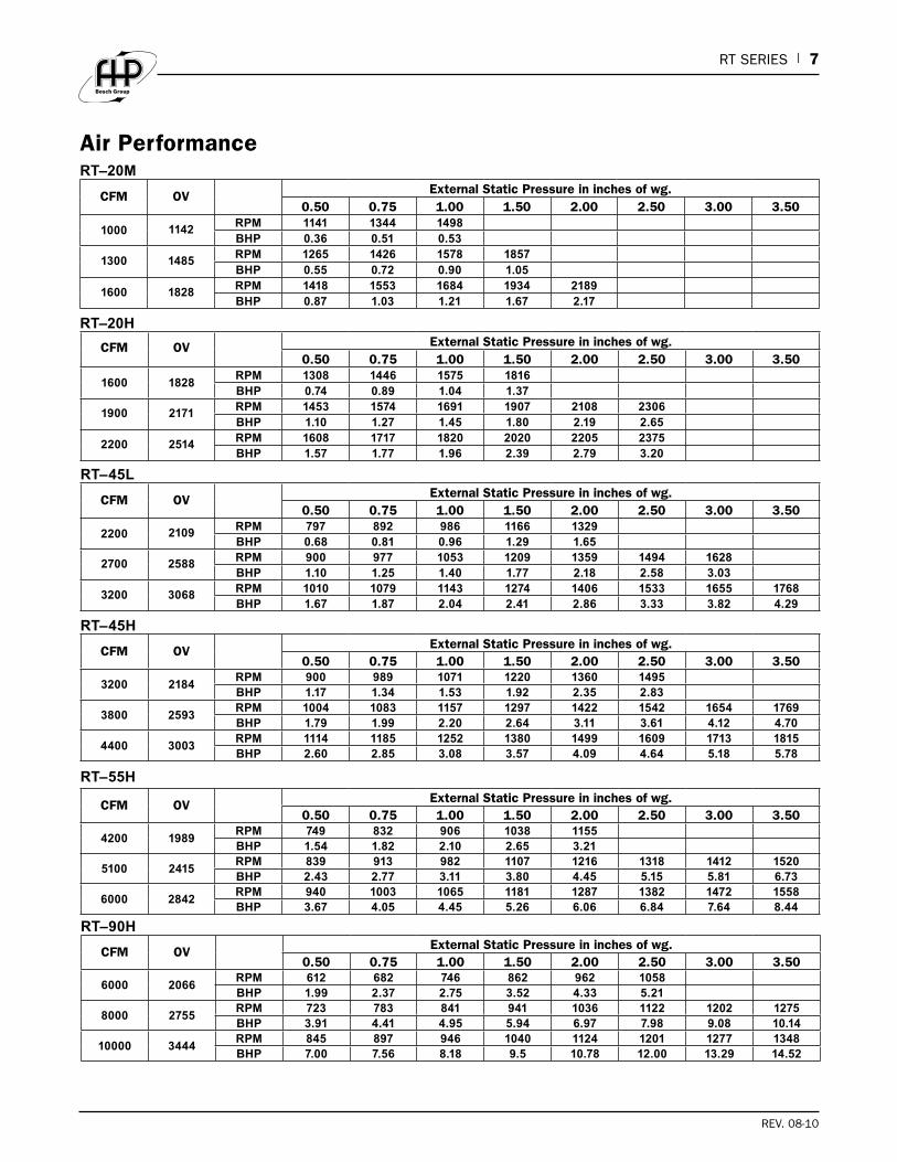
Air Performance
Intake and Discharge Options With the RT Series, you have many air intake and discharge options available to simplify duct layout for rooftop and equipment room installations. Refer to the table below for the intake and discharge locations available for outdoorair(OA)andexhaustair(EA).
The air performance data on page 6 accounts for the pressure drop across the energy recovery wheel and the internal housing losses, but does not include pressure drop for filters or air coil.
Addfilterand/oraircoilpressuredrop(fromthetablesbelow)toexternalstaticpressuretodetermine correct rpm and horsepower.
Filter Pressure Drop (33% eff.)
Model CFM Pressure Drop (in. wg)
RT-201000 0.04
2200 0.22
RT-452200 0.06
4400 0.24
RT-554200 0.09
6000 0.18
RT-906000 0.10
10000 0.27
Tempering Options Pressure Drop
Model CFM Pressure Coil (in. wg)
RT-201000 0.17
2200 0.62
RT-452200 0.31
4400 0.66
RT-554200 0.38
6000 0.64
RT-906000 0.28
10000 0.66
Bottom Top Side End
OA Intake X X
OA Discharge X X X1 X2
EA Intake X X X
EA Discharge X X X1Side OA Discharge is ONLY available with the Indirect Gas (IG) heater.
2End OA Discharge is NOT available with the Indirect Gas(IG) heater.
RT SERIES | 7
REV. 08-10
Air Performance
CFM OV External Static Pressure in inches of wg.0.50 0.75 1.00 1.50 2.00 2.50 3.00 3.50
1000 1142RPM 1141 1344 1498BHP 0.36 0.51 0.53
1300 1485RPM 1265 1426 1578 1857BHP 0.55 0.72 0.90 1.05
1600 1828RPM 1418 1553 1684 1934 2189BHP 0.87 1.03 1.21 1.67 2.17
RT–20M
CFM OV External Static Pressure in inches of wg.0.50 0.75 1.00 1.50 2.00 2.50 3.00 3.50
1600 1828RPM 1308 1446 1575 1816BHP 0.74 0.89 1.04 1.37
1900 2171 RPM 1453 1574 1691 1907 2108 2306BHP 1.10 1.27 1.45 1.80 2.19 2.65
2200 2514 RPM 1608 1717 1820 2020 2205 2375BHP 1.57 1.77 1.96 2.39 2.79 3.20
RT–20H
CFM OV External Static Pressure in inches of wg.0.50 0.75 1.00 1.50 2.00 2.50 3.00 3.50
2200 2109 RPM 797 892 986 1166 1329BHP 0.68 0.81 0.96 1.29 1.65
2700 2588 RPM 900 977 1053 1209 1359 1494 1628BHP 1.10 1.25 1.40 1.77 2.18 2.58 3.03
3200 3068 RPM 1010 1079 1143 1274 1406 1533 1655 1768BHP 1.67 1.87 2.04 2.41 2.86 3.33 3.82 4.29
RT–45L
CFM OV External Static Pressure in inches of wg.0.50 0.75 1.00 1.50 2.00 2.50 3.00 3.50
3200 2184RPM 900 989 1071 1220 1360 1495BHP 1.17 1.34 1.53 1.92 2.35 2.83
3800 2593RPM 1004 1083 1157 1297 1422 1542 1654 1769BHP 1.79 1.99 2.20 2.64 3.11 3.61 4.12 4.70
4400 3003RPM 1114 1185 1252 1380 1499 1609 1713 1815BHP 2.60 2.85 3.08 3.57 4.09 4.64 5.18 5.78
RT–45H
CFM OV External Static Pressure in inches of wg.0.50 0.75 1.00 1.50 2.00 2.50 3.00 3.50
4200 1989RPM 749 832 906 1038 1155BHP 1.54 1.82 2.10 2.65 3.21
5100 2415RPM 839 913 982 1107 1216 1318 1412 1520BHP 2.43 2.77 3.11 3.80 4.45 5.15 5.81 6.73
6000 2842RPM 940 1003 1065 1181 1287 1382 1472 1558BHP 3.67 4.05 4.45 5.26 6.06 6.84 7.64 8.44
RT–55H
CFM OV External Static Pressure in inches of wg.0.50 0.75 1.00 1.50 2.00 2.50 3.00 3.50
6000 2066RPM 612 682 746 862 962 1058BHP 1.99 2.37 2.75 3.52 4.33 5.21
8000 2755RPM 723 783 841 941 1036 1122 1202 1275BHP 3.91 4.41 4.95 5.94 6.97 7.98 9.08 10.14
10000 3444RPM 845 897 946 1040 1124 1201 1277 1348BHP 7.00 7.56 8.18 9.5 10.78 12.00 13.29 14.52
RT–90H

8 | RT SERIES
970-457
Series RT Energy Recovery Rooftop System Specification
General: Packaged Energy Recovery Units shall be fully assembled at the factory. Unit shall be suitable for installation outdoors on a roof and designed to pre-treat 100% outdoor air. Units shall comprise the following sections:
•Water-cooled,reversecycleheatpump
•AirtoAirheatwheelheatrecovery
•Filtersectioninbothsupplyandexhaustsections
•Supplyfan
•Exhaustfan
Units shall be UL or ETL Listed. Energy recovery wheel shall be ARI 1060 Certified. Unit shall bear the AMCA Certified Rating seal for Air Performance.
Unit Casing and Frames: Unit construction shall be suitable for indoor and outdoor installations. Exterior panels shall be either galvanized, baked enamel or prepainted steel. Unit shall be of internal frame type construction of galvanized steel. Frame and panels shall beG90galvanizedsteel.Unitshallbeinternallylinedwith galvanized sheet metal creating a double wall. Where top panels are joined there shall be an overlapping, standing seam to insure positive weather protection. All metal-to-metal seams shall be factory sealed, requiring no caulking at job site. Unit base to be designed for curb mounting. Unit base shall overhang the curb for a positive seal against water run-off.
Weather hoods: Weather hoods shall be the same finish as the unit. Outdoor air weather hood shall incorporate a louvered design and moisture eliminator. Weather hoods shall be tested in accordance with AMCA Standard 500-L to prevent water penetration up to 3 in/hr at 29 mph.
Insulation: Unit casing to be insulated with 1-inch fiberglass. Insulation shall have a maximum flame spread of 25 and smoke developed of 50, when tested in accordance with ASTM C 411. Insulation shall be enclosed in double wall construction and provide full coverage of the entire cabinet including walls, roof and floor.
Intake and Discharge Options: Outdoor Air Intake shall beToporEnd.OADischargeshallbeBottom,ToporEnd. Exhaust Air Intake shall be Bottom, Top or End. ExhaustAirDischargeshallbeTop,SideorEnd.
Dampers: Dampersshallbemotorized and be wired to a single point power disconnect. Intake and exhaust dampers shall be internally mounted at the air inlet.
P Trap:APtrap(condensatedrain)assemblyshallbeprovidedfor each unit, to include cleanout ports, cleanout tool, vacuum break device and see-through reservoir to permit visual verification of water or glycol solution levels.
Energy Recovery Wheel: Wheel shall be of the total enthalpy rotary air-to-air type for both sensible and latent energy recovery and be designed to insure laminarflow.Desiccantshallbesilicagelformaximumlatent energy transfer. Wheel shall be constructed of lightweight polymer media to minimize shaft and bearing loads. Polymer media shall be mounted in a stainless steel rotor for corrosion resistance.
Wheel design shall consist of removable segments for ease of service and/or cleaning. Silica gel desiccant shall be permanently bonded to wheel media to retain latent heat capability after cleaning. Energy recovery drive belt material shall be high strength urethane and shall be factory installed in a pre-stretched state, eliminating the need for field belt tension adjustment. Link style belts are not acceptable.
The entire heat recovery wheel assembly shall be capable of being easily removed for cleaning.
Performance criteria are to be as specified in AHRI Standard 1060, complying with the Combined Efficiency data in the submittal.
Hinged Access Doors: All components shall be easily accessible through hinged access doors for exhaust, supply, filter, and damper compartments. Energy recoverywheels(smallerthan58inches)shallbemounted in a slide-out track for ease of inspection, removal, and cleaning.
Roof Curbs: Roof curb to be supplied by unit manufacturer for field assembly. Curb shall consist of die formed galvanized steel sections. Curb shall be full perimeter type with gasketing provided for field installation between curb and unit base.
Fan Sections: Centrifugal fans to be double width, double inlet, forward curved type. All blower wheels shallbestaticallyanddynamicallybalanced.Groundand polished steel fan shafts shall be mounted in

RT SERIES | 9
REV. 08-10
permanently lubricated, sealed ball bearing pillow blocks. Bearings shall be selected for a minimum (L10)lifeinexcessof100,000hoursatmaximumcataloged operating speeds. Separate motors for exhaust and supply blowers shall be provided. Adjustable sheaves on belt-driven fans with motors less than 10 hp shall allow independent balancing of exhaust and supply airflow. Fan and motor assemblies are mounted to heavy gauge galvanized rails with neoprene isolators as standard. Fans shall be located in draw-through position in reference to the energy recovery wheel.
Motors and Drives: Motors shall be energy efficient, complying with EPACT standards. Motors shall be permanently lubricated, heavy-duty type, matched to the fan load and furnished at the specified voltage, phase,andenclosure.Drivesshallbesizedforaminimum of 150% of driven horsepower. Pulleys shall be of the fully machined cast type, keyed and securely attached to the fan wheel and motor shafts; 10 hp and less shall be supplied with an adjustable drive pulley. Energy wheel motors shall have integral overload protection.
Optional Variable Frequency shall be factory installed for modulation of the intake and exhaust blower assemblies.InadditionaVFDshallbeavailableforthe energy wheel drive motor.
Filters: Supply and exhaust air filters shall be MERV 8 2-inch thick pleated fiberglass, tested to meet UL Class 2. Optional combination MERV 8 and MERV 13 pleated fiberglass shall be provided on the outside air stream.
Heat Pump ModuleModules shall be suitable for a geothermal operation and utilize refrigerant R-410A. All modules shall contain a sealed refrigerant circuit including the following components:
•Hermeticcompressor(s)withcrankcaseheater,
•Balanceportexpansionvalve(s)
•Refrigerantdrier(s)
•Refrigerantreversingvalve(s)
•Serviceports
•Hotgasbypassoncircuitone
•Suctionlineaccumulators
Compressor shall be high efficiency scroll, designed for heat pump duty and mounted on rubber vibration isolators. Compressor motors shall be equipped with overload protection. Unit sizes 096 and larger shall have independent dual refrigerant circuits.
Refrigerant reversing valves shall be pilot operated sliding piston type with replaceable encapsulated magnetic coils energized only during the cooling cycle.
All refrigerant lines, except hot gas lines, shall be insulated.
The coaxial water-to-refrigerant heat exchanger shall be constructed as follows:
•Convolutedcopperinner-tubeandsteeloutertubewithadesignedrefrigerantworkingpressureof600PSIG(4125kPa).
•Designedwatersideworkingpressureofnolessthan400PSIG(2750kPa).
Safety devices shall include:
•Lowpressurecutoutseta40PSIG(275kPa)forlossofchargeprotection(freeze-statand/or high discharge gas temperature sensor is not acceptable).
•Highpressurecutoutcontrolsetat600PSIG(4125kPa).
Options for heat pump:
•Modulatinghotgasreheat
•Cupro-Nickelrefrigeranttowatercoils
Heat Pump Controls A control box shall be located within the unit and shall contain a printed circuit UPM control board, controls for compressor, reversing valve, and optional condensate safety sensor and freeze stat. Unit controls shall be 24 volts and shall provide heating or cooling as required by the temperature control system.
The unit-mounted UPM heat pump control system shall have the following features:
•Anti-shortcycletimedelayoneachcompressoroperation.
•Randomstartonpowerupmode.
•Lowvoltage(BrownOut)interruptionprotectionforeach compressor circuit.
•120-secondbypasstimerforthelowpressureswitch.
•Shutdownonhighorlowrefrigerantpressureswitch,optional freezestat or condensate sensor.
•Optionalfreezestatsetat35°F
•Alarmoutputwhichclosesforremotefaultindication, pulsed or constant output based on specificfault(selectable).
•ResetofaunitsafetyswitchatthewallPCoratthemain power disconnect.
10 | RT SERIES
970-457
•Automaticintelligentreset.Unitshallautomaticallyreset the unit twice after a safety shut down before going into a hard lockout.
•Abilitytodefeattimedelaysforservicing.
•ALEDtoindicatesafetyalarms.TheLEDshallannunciate the following alarms: high refrigerant pressure, low refrigerant pressure, low water temperature, or a high level of condensate in the drain pan.
Cooling Coil:Directexpansion(DX)coilsshallbeAHRICertified and factory tested and rated in accordance with ARI 410. Coils shall have copper tubes with permanentlyexpandedaluminumfins.DXcoilsshallbeequipped with distributors to receive expansion valves attheliquidconnections.Dualcompressorunitsshallhave interlaced refrigerant circuiting to provide active cooling or heating of the entire face area at part load operation.
Drain Pans:DrainpanshallbeformedofweldedAustenitic stainless steel sheet material and provided with a welded drain connection at the front for connection to a P trap.
Electrical: All internal electrical components shall be factory wired for single point power connection. All electrical components shall be UL or ETL Listed, Approved, or Classified where applicable and wired in compliance with the National Electrical Code. Weatherproof, integral door interlocking disconnect switch, motor starters, control circuit fusing, control transformer for 24 VAC circuit, and terminal strip shall be supplied as standard components in the control center. Motor starters consist of a contactor and Class 20 electronic adjustable overload protection and shall be provided for all fan motors.
Microprocessor Discharge Temperature Control (Optional)The microprocessor controller is specifically designed and programmed to optimize the performance of an RT unit with supplemental heating and cooling. This option ensures that the outdoor air is conditioned to the desired discharge conditions. The controller and accompanying sensors are factory mounted, wired and programmed.Defaultsettingsarepreprogrammed,butare easily field adjustable. The microprocessor controller can be interfaced with a Building ManagementSystem(BMS)throughLonWorks,BACNET, or ModBus.
The unit mounted controller shall be capable of functioning as a stand-alone heating and cooling system controlled by the factory-supplied controllers,
thermostats and sensors or it can be operated as a heating and cooling system controlled by a Building ManagementSystem(BMS).
This energy recovery unit shall be controlled by a factory-installed microprocessor programmable controller that is connected to various optional sensors that may have either analog or digital output.
Roomdisplay(s)shallbeavailablethatfunctionasremote indicators of owner-selected operating parameters and also permit remote input of new operating parameters. Installed location of room display(s)shallbeasindicatedontheplans.
Supplemental Hot Water Coil: Hot water coil shall be factory tested and rated in accordance with ARI 410. Coils shall have copper tubes with permanently expanded aluminum fins, 12 fpi or less.
Auxiliary Electric Heat: Electric heat shall be UL listed and circuit fused per NEC over 48 amps. Heater shall be multi-step control, factory wired and installed. Control will be 24 volt with class 2 transformer. Standard air flow switch to shut down heater if air ceases to flow across heater.
Frost ControlUnits shall be equipped with optional frost control to prevent frosting on the energy recovery wheel in sub zero ambient conditions. An electric heater shall preheat outside air prior to entering the heat recovery wheel. The heater control shall be triggered by the outdoor air temperature set point in conjunction with the an increased pressure drop across the energy wheel.
Rotation SensorThe unit shall be equipped with an optional wheel rotation sensor. When a wheel rotation failure occurs a signal shall be sent to an indicator light.
Economizer ControlUnits shall be equipped with an optional economizer (freecooling)control.Thisshallcompriseofeither:
Wheel Off:De-energizesthewheelwhentheoutdoortemperature is below the field adjustable set point or
Wheel Modulation: Modulates the energy recovery wheel to maintain a 55°F discharge temperature during economizer operation
Variable Air Volume OperationUnit shall be provided with variable frequency drives for modulating or multi speed blower control. A separate VFDshallbeprovidedforeachblowermotor.
RT SERIES | 11
REV. 08-10
Weather HoodsA louvered intake hood with 2-inch aluminum mesh filters, and an exhaust hood with an integral back draft damper are available.
Dampers — Internally MountedA variety of motorized control dampers are available. Intake and exhaust dampers are internally mounted at theoutdoorandexhaustairinlets.Dampersarefactorywired to a single point power disconnect.
FiltersStandard size 2-inch, MERV 8, pleated, medium efficiency filters and filter racks are available for outdoor air and/or exhaust air streams.
Accessories:•RemotePanels
•GFCIServiceOutlet(controlpowerbyothers)
•ServiceLights(controlpowerbyothers)
•SpareWheelSegments
•RoofCurbs
•PaintedExteriors
•FactoryMountedSensors
•HighFilterefficiencyoption

RT ROO
FTO
P
SERIES
970-457
601 N.W. 65th Court, Ft. Lauderdale, FL 33309Phone: 954-776-5471 | Fax: 954-776-5529www.boschtaxcredit.com | www.fhp-mfg.com


![Notice of Decision the rooftop addition and rooftop patio ...€¦ · the rooftop addition and rooftop patio, 5.54 metres by 4.04 metres) [2] The subject property is on Condo Common](https://static.fdocuments.in/doc/165x107/5fbd4da09cef473df80642ed/notice-of-decision-the-rooftop-addition-and-rooftop-patio-the-rooftop-addition.jpg)