
Energy Management for Fuel Cell Powered Hybrid-Electric...
22
American Institute of Aeronautics and Astronautics 1 Energy Management for Fuel Cell Powered Hybrid- Electric Aircraft Thomas H. Bradley 1 Colorado State University, Fort Collins, Colorado, 80523-1374 Blake A. Moffitt 2 , David E. Parekh 3 United Technologies Research Center, East Hartford, Connecticut, 06108 and Thomas F. Fuller 4 , Dimitri N. Mavris 5 Georgia Institute of Technology, Atlanta, Georgia, 30332-0150 Many researchers have proposed hybridization of fuel cell powerplants for unmanned aerial vehicles with the goal of improving the aircraft performance. The mechanisms of this performance improvement are not well understood. This work poses the problem of deriving energy management strategies for fuel cell powered, hybrid fuel cell powered and internal combustion powered aircraft as an optimal control problem. Dynamic programming and sequential quadratic programming are used with reduced order dynamic models to solve for optimal energy management strategies and optimal flight paths for these aircraft. Results show that hybridization and flight path management does not improve the endurance of fuel cell powered aircraft for a fixed airframe design, as it can for internal combustion powered aircraft. During the aircraft design process, hybridization does allow the aircraft power constraints to be decoupled from the aircraft energy requirements, with beneficial results in an integrated aircraft design process. Nomenclature α = angle of attack, rad α max = angle of attack at stall, rad b = vector of controls for sequential quadratic programming routine C = battery coulombic capacity, Ah C D,0 = aircraft coefficient of drag at α = 0 C D,α = derivative of aircraft coefficient of drag w.r.t. α C L,0 = aircraft coefficient of lift at α = 0 C L,α = derivative of aircraft coefficient of lift w.r.t. α C q = propeller coefficient of torque C T = propeller coefficient of thrust D = drag force, N d = propeller diameter, m f() = function operator 1 Assistant Professor, Department of Mechanical Engineering, Fort Collins, Colorado 80523-1374, AIAA Member. 2 Senior Engineer/Scientist, United Technologies Research Center, 411 Silver Lane MS129-01, East Hartford, Connecticut 06108, AIAA Member. 3 VP Research and Director, United Technologies Research Center, 411 Silver Lane MS129-01, East Hartford, Connecticut 06108, Associate Fellow of AIAA. 4 Professor, School of Chemical & Biomolecular Engineering, 311 Ferst Drive N.W., Atlanta, Georgia 30332-0100. 5 Boeing Professor of Advanced Aerospace Systems Analysis, The Daniel Guggenheim School of Aerospace Engineering, 270 Ferst Drive N.W. Atlanta, Georgia 30332-0150, Associate Fellow of AIAA. 7th International Energy Conversion Engineering Conference 2 - 5 August 2009, Denver, Colorado AIAA 2009-4590 Copyright © 2009 by T. H. Bradley. Published by the American Institute of Aeronautics and Astronautics, Inc., with permission.
Transcript of Energy Management for Fuel Cell Powered Hybrid-Electric...

American Institute of Aeronautics and Astronautics
1
Energy Management for Fuel Cell Powered Hybrid-
Electric Aircraft
Thomas H. Bradley1
Colorado State University, Fort Collins, Colorado, 80523-1374
Blake A. Moffitt2, David E. Parekh3
United Technologies Research Center, East Hartford, Connecticut, 06108
and
Thomas F. Fuller4, Dimitri N. Mavris5
Georgia Institute of Technology, Atlanta, Georgia, 30332-0150
Many researchers have proposed hybridization of fuel cell powerplants for
unmanned aerial vehicles with the goal of improving the aircraft performance. The mechanisms of this performance improvement are not well understood. This work
poses the problem of deriving energy management strategies for fuel cell powered,
hybrid fuel cell powered and internal combustion powered aircraft as an optimal
control problem. Dynamic programming and sequential quadratic programming
are used with reduced order dynamic models to solve for optimal energy
management strategies and optimal flight paths for these aircraft. Results show
that hybridization and flight path management does not improve the endurance of
fuel cell powered aircraft for a fixed airframe design, as it can for internal
combustion powered aircraft. During the aircraft design process, hybridization
does allow the aircraft power constraints to be decoupled from the aircraft energy
requirements, with beneficial results in an integrated aircraft design process.
Nomenclature
α = angle of attack, rad
αmax = angle of attack at stall, rad
b = vector of controls for sequential quadratic programming routine C = battery coulombic capacity, Ah
CD,0 = aircraft coefficient of drag at α = 0
CD,α = derivative of aircraft coefficient of drag w.r.t. α CL,0 = aircraft coefficient of lift at α = 0
CL,α = derivative of aircraft coefficient of lift w.r.t. α Cq = propeller coefficient of torque
CT = propeller coefficient of thrust
D = drag force, N
d = propeller diameter, m
f() = function operator
1Assistant Professor, Department of Mechanical Engineering, Fort Collins, Colorado 80523-1374, AIAA Member. 2Senior Engineer/Scientist, United Technologies Research Center, 411 Silver Lane MS129-01, East Hartford, Connecticut 06108, AIAA Member. 3VP Research and Director, United Technologies Research Center, 411 Silver Lane MS129-01, East Hartford, Connecticut 06108, Associate Fellow of AIAA. 4Professor, School of Chemical & Biomolecular Engineering, 311 Ferst Drive N.W., Atlanta, Georgia 30332-0100. 5Boeing Professor of Advanced Aerospace Systems Analysis, The Daniel Guggenheim School of Aerospace
Engineering, 270 Ferst Drive N.W. Atlanta, Georgia 30332-0150, Associate Fellow of AIAA.
7th International Energy Conversion Engineering Conference 2 - 5 August 2009, Denver, Colorado
AIAA 2009-4590
Copyright © 2009 by T. H. Bradley. Published by the American Institute of Aeronautics and Astronautics, Inc., with permission.

American Institute of Aeronautics and Astronautics
2
γ = aircraft flight path angle, rad
g = acceleration due to gravity, m/s2
γclimb = aircraft flight path angle during climb, rad
gcost = cost weighting function
γglide = aircraft flight path angle during gliding descent, rad
h = aircraft altitude, m
ηLHV = fuel cell lower heating value based efficiency Ib = battery current, A
Ibmax = maximum battery power, W
Ibmin = minimum battery power, W
IFC = fuel cell stack current, A
IMOTOR = electric motor current, A
J = propeller advance ratio
Jcost = objective function
k = discrete index
L = lift force, N
m = aircraft mass, kg
N = number of discrete times
p = propeller pitch, m Pbatt = battery power, W
PFC = fuel cell power, W
PICE = internal combustion engine power, W
PP = electrical power to the propulsion motor, W
Q = propeller and electric motor torque, Nm
qLHV = lower heating value of hydrogen, J/kg
ρ = air density, kg/m3
Rint = battery internal ohmic resistance, Ω S = vector of states for dynamic programming routine
SOC = battery state of charge
SOCf = final battery state of charge
SOCi = initial battery state of charge Sw = wing area, m2
T = thrust force, N
τ = time period of periodic optimal control
u = vector of controls for dynamic programming routine
v = airspeed, m/s
V = dynamic programming cost to go function
VFC = fuel cell potential, V
w = vector of disturbances
Ωb = vector of admissible controls for sequential quadratic programming routine
ωmotor = propulsion electric motor output speed, rad/sec
ΩS = vector of admissible states for dynamic programming routine
Ωu = vector of admissible controls for dynamic programming routine
Ωy = vector of admissible states for sequential quadratic programming routine
y = vector of states for sequential quadratic programming routine
2HW& = flow rate of hydrogen, kg/sec
I. Introduction
Fuel cell powered aircraft have been of long term interest to the aviation community because of their
potential for improved performance and environmental compatibility. Only recently have improvements in
the technological readiness of fuel cell powerplants enabled the first aviation applications of fuel cell
technology. Because of the evolving nature of the technology, many aspects of the performance, design
and construction of robust and optimized fuel cell powered aircraft are under continuing refinement. This
study aims to determine the effectiveness of powerplant hybridization and flight path optimization in
improving the performance of fuel cell powered aircraft.

American Institute of Aeronautics and Astronautics
3
Hybridization has been proposed as a means to improve the performance of fuel cell powerplants for
aircraft [1][2][3]. In general, hybridization can allow the power and energy demands of the fuel cell system
to be isolated from those required of the aircraft. For example, a hybrid aircraft that must transition from
cruise to climb can do so with the assistance of stored energy from an energy buffer. Decoupling the
aircraft power demands from the fuel cell power demands may be able to improve the efficiency of the
maneuver by allowing the fuel cell powerplant to maintain operation at near optimal conditions. Other means of improving the energy management of an aircraft through hybridization such as regenerative wind-
milling, regenerative solar energy capture, and accessory load electrification are not considered in this
study.
Aviation flight path optimization is an important and well developed field whose goal is the derivation
of control strategies to improve the endurance or range of a variety of aircraft [4][5][6][7]. A majority of
the studies of optimal periodic control have focused on gas turbine or internal combustion engine
powerplants. For fuel cell powered aircraft flight path optimization has primarily been considered in the
contexts of thermal soaring for range extension [1], and diurnal flight paths for solar powered fuel cell
aircraft [8][9]. In this study we consider the more general problem of evaluating the effectiveness of flight
path optimization for range and endurance optimization without external energy inputs.
In this work, energy management for hybrid fuel cell aircraft and flight path optimization for fuel cell
aircraft are evaluated in simulation for their effect on the flight performance of a fuel cell powered aircraft. We would like to discover and quantify the benefits (if any) of hybridization and flight path optimization in
fuel cell powered aircraft. Two non-linear programming algorithms are implemented in order to determine
the effectiveness and characteristics of optimal energy management strategies for fuel cell powered aircraft.
First, a dynamic programming algorithm is proposed with reduced order models of the fuel cell powerplant,
aircraft dynamics and energy consumption. Next, a sequential quadratic programming routine is used to
evaluate the possibility of extending endurance of fuel cell powered aircraft using flight path optimization.
Simulation results with the optimal control strategies are presented for a variety of generic fuel cell aircraft
missions. For comparison, optimal flight paths and energy management strategies are derived for an
example aircraft powered by an internal combustion engine. Discussion focuses on an efficiency
comparison of hybridization to flight path optimization and a discussion of regimes of effectiveness for
both strategies.
II. Problem Formulation
The aircraft that are under consideration for this study are represented by a set of simplified component
models that are derived from experimental data. Simplifications to the aircraft and powerplant models are required in order to cast the problem as a controls optimization problem of sufficient scope to reach
generalizeable conclusions. The model simplifications are applied to be able to isolate the phenomena of
interest: long-period, optimal energy management behavior.
A. Aircraft Characteristics To simply the problem of flight path optimization, the aircraft is constrained to a flight path in a
vertical plane. The aircraft neither turns nor banks. Using a flat earth coordinate system the equations of
motion of the aircraft are as follows [10].
γsinvh =& (1)
γα
sincos
gm
DTv −
−=& (2)
γα
γ cossin
v
g
vm
LT−
+=& (3)
Aircraft lift and drag are defined as:

American Institute of Aeronautics and Astronautics
4
( )0,
2
2
1LLw
CCSvL +⋅= αρ α (4)
( )0,
2
2
1DDw
CCSvD +⋅= αρ α (5)
The mass and aerodynamic characteristics of the aircraft, presented in Table 1, are derived from fuel
cell powered aircraft design studies from literature [11][12].
Table 1. Low fidelity aircraft model characteristics for energy management studies Aircraft Model Characteristic
Value
α,LC 0.0979 rad-1
0LC 0.482
α,DC 0.0029 rad-1
0DC 0.0229
wS 1.08 m2
m 12.5 kg
d 0.52 m
p 0.37 m
B. Fuel Cell Powertrain Modeling The fuel cell system is the primary power source for the fuel cell aircraft. A fuel cell is a direct
electrochemical conversion device that converts reactants into products and electrical power. The fuel cell
powerplant is modeled as a static polarization curve that represents the performance of the fuel cell stack
and balance of plant systems. The performance of the fuel cell used in this study is based on direct
hydrogen polymer electrolyte membrane fuel cell technology. This study assumes that the hydrogen
reactant for the fuel cell powerplant is stored on board the aircraft in a compressed pressure vessel, and that the oxygen reactant is supplied from ambient air. The hydrogen consumption and fuel cell lower heating
value efficiency are functions of fuel cell output power as shown in Figure 1 and Figure 2. These curves
are based on fits to experimental system test data [11][13]. They include the effects of plant energy
consumption, hydrogen utilization, varying cathode stoichiometry and balance of plant loads. The fuel cell
system output power is calculated as the product of fuel cell system voltage and current:
FCFCFC IVP ⋅= (6)
The LHV efficiency of the fuel cell is the ratio of fuel cell output power to the heating value of the
hydrogen flow into the system.
2HLHV
FCLHV
Wq
P
&⋅=η
(7)
The dynamics of air handling, water transport and electrochemistry for the fuel cell stack and balance of plant are not modeled as they are known to take place at a frequency much greater than the bandwidth of
the aircraft and energy management controller [13].

American Institute of Aeronautics and Astronautics
5
Figure 1. Fuel cell hydrogen consumption model
Figure 2. Fuel cell efficiency model
The aircraft electric motor is modeled using a 3 layer perceptron neural network surrogate model
trained using experimental data from dynamometer motor testing [14]. The neural network model outputs
the efficiency of the electric motor and motor controller as a function of output torque, input voltage and
motor rotational speed. A subset of the electric motor surrogate model behavior is shown in Figure 3 and
Figure 4. Motor efficiency is calculated as the ratio of mechanical output power to DC electrical input power:
MOTORFC
MOTOR
MOTORIV
Q
⋅
⋅=
ωη (8)
Figure 3. Electric motor efficiency map at motor
input potential of 40V
Figure 4. Electric motor model training data set

American Institute of Aeronautics and Astronautics
6
Figure 5. Propeller thrust coefficient model
Figure 6. Propeller torque coefficient model
The propeller model is used to relate the electric motor torque to the aircraft thrust. The thrust, T,
applied to the aircraft is defined by, [10][17]
TCdT
4
2
2
=
π
ωρ (9)
The propeller torque, Q, to be applied to the electric motor is determined from the software propeller
model using the relation:
qCdQ
5
2
2
=
π
ωρ (10)
Both the thrust and torque coefficients, Cq and CT, are a function of the propeller advance ratio J, as
shown in Figure 5 and Figure 6. The performance of the propeller is derived from wind tunnel test data
[16].
d
vJ
=
π
ω
2
(11)
C. Hybrid Energy Storage System Modeling The hybrid energy storage system is modeled as a pack of model 18650 lithium polymer battery cells.
The open circuit voltage and internal resistance characteristics of each 18650 cell are derived from
experimental data from the literature and are summarized in Figure 7 and Figure 8 [18]. The battery pack
is assembled with each cell in electrical series so that when current into the battery has positive sign,
intbbOCbattRIIVP
2+=
(12)

American Institute of Aeronautics and Astronautics
7
Figure 7. Lithium Ion battery open circuit
voltage model
Figure 8. Lithium Ion battery internal resistance
model
Figure 9. Hybrid electric fuel cell airplane diagram
Figure 9 shows a schematic of the aircraft powerplant. Between the battery pack and the fuel cell
power bus is a power management system that allows the battery pack to discharge power to the fuel cell
power bus and to charge from the power bus without requiring a matching of the fuel cell bus voltage and
battery voltage. The power management device provides design freedom to specify the battery bus voltage
and fuel cell bus voltage independently. The battery and fuel cell power sum to provide the electrical
power to the electric motor such that :
PbattFCPPP =−
(13)
The battery model assumes that the battery coulombic efficiency is 100%, so that the state of charge
can be defined as:
C
dtISOC
b∫=
(14)
The battery capacity C = 12Ah. The battery energetic efficiency is defined by the ratio of the electrical
energy that enters the battery to the energy extracted from the battery at constant state of charge. The
energetic efficiency of the battery is less than 100% because of losses from ohmic losses during charging
and discharging that are modeled using the battery internal resistance. The thermal state of the battery is
not modeled.

American Institute of Aeronautics and Astronautics
8
D. Internal Combustion Engine Powertrain Modeling In order to make a comparison between the energy management strategies for fuel cell powered aircraft
and those of conventional internal combustion aircraft, we will repeat the analyses with an internal
combustion powerplant model. The internal combustion engine model is based on experimental testing of
the UAV engine that powers the commercial UAV Aerosonde [15]. The performance and efficiency of the
internal combustion engine are shown in Figure 10 and Figure 11. This analysis assumes that the internal combustion engine does not idle and that it can be restarted instantly.
Figure 10. Internal combustion engine fuel consumption model
Figure 11. Internal combustion engine efficiency
model
E. Energy Management Optimization Algorithms Two nonlinear programming algorithms are used to determine the effectiveness of flight path
optimization and hybridization as means to improve the performance of the fuel cell powered aircraft.
First, a dynamic programming routine is used to determine the effectiveness of varying degrees of
hybridization for varying aircraft flight profiles. Next a sequential quadratic programming routine is used
to compare the effects of flight path optimization on both fuel cell powered and internal combustion engine
powered aircraft.
Investigation I In the first part of this study, a dynamic programming algorithm will be used to derive optimal
battery/fuel cell power flows so as to optimize the endurance of the hybrid electric aircraft for predetermined flight paths. The resulting optimal energy consumptions can be compared among battery
sizes and flight profiles to define optimal degrees of hybridization for fuel cell hybrid aircraft.
The aircraft can be described with the nonlinear system dynamics equation
),,( wuSfS =& (15)
The problem is then to determine the control sequence in discrete time,
1...2,1,0),( −= Nkku (16)
that minimizes the objective function,
( ) ( ) ( )[ ]∑−
=
=1
0
costcost
N
k
kw,ku,kSgJ, (17)

American Institute of Aeronautics and Astronautics
9
subject to state and control constraints,
( ) ( ) [ ] [ ] )()()(|)(
)()0(%90)(%20|)(
maxminkSIkkSIkku
SOCNSOCkkkS
bubu
fSiSSS
≤Ω≤Ω∈
=Ω∩=Ω∩≤Ω≤Ω∈ (18)
The objective function Jcost is a summation of the fuel consumption at each stage g(k), so that
minimization of Jcost maximizes aircraft endurance given a fixed fuel storage. The fuel consumption at
each stage g(k) is calculated from the set of equations (6,7,12-14,17,18) and the data in Figures 1,2,7,8,10,
and 11 with S(k)=SOC, u(k)=Ib and w(k)=PP as inputs. The state of charge is constrained to remain within a recommended state of charge range where SOCmin=20% and SOCmax=90%. The initial and final states of
charge (SOCi and SOCf) are constrained to ensure that the change in state of charge over the flight is small.
The battery current is constrained to remain within the battery charging current limits (maxb
I ) and
discharging current limits (minb
I ), which are calculated at each stage from the battery state of charge.
Deterministic dynamic programming proceeds by splitting the N-stage optimal control problem into a
set of recursive 1-stage problems, with discrete states. Working backwards in time, dynamic programming
with backward induction defines a cost to go V(S(k),k) at each state S(k). The cost to go defines the
minimum cost to proceed from S(k) to each final state S(N). The optimal control policy u(k) satisfies the
Bellman principal of optimality:
[ ])k),k(S(V))k(u),k(S(Jmin)k),k(S(V +−−=−− 1111 cost (19)
This equation allows for the recursive calculation of the optimal control sequence u(k) beginning from
S(N). The state space is discretized into 20,000 discrete states (a spacing of 0.00005 SOC) at N=1000
points in time. Dynamic programming algorithm explores all possible control policies to reach a global
optimum in the discretized time-space domain.
Investigation II In the second part of this study, a sequential quadratic programming algorithm will be used to
determine the effectiveness of flight path optimization for fuel cell powered aircraft. No hybrid energy
storage is considered in this part of the study. The optimal flight path results for the fuel cell powered
aircraft will be compared to results for an internal combustion powered aircraft.
This problem is posed as an optimal periodic endurance problem where the periodic flight of duration τ is split into two phases: a gliding flight phase (k=0), and a powered climb phase (k=1). The prototypical
flight path is shown in Figure 12.
Figure 12. Diagram showing climb-glide flight path template for flight path optimization
The aircraft and powerplant systems can be described with the nonlinear dynamic equations

American Institute of Aeronautics and Astronautics
10
=
=
=
Tb
vy
byfy
α
γ
),(&
(20)
The state variable y includes the velocity of the aircraft v and the flight path angle γ. The control
variables are the propulsive thrust T and the aircraft angle of attack α. The problem is then to determine the discrete control sequence
1,0),( =kkb, (21)
that minimizes the objective function,
( ) ( )[ ]∑
=
=1
0
,
k
kbkygR
τ , (22)
subject to state and control constraints,
( )
( )
∞≤ΩΩ∈
Ω≤
∞−Ω∈
max)(|)(
)(0
|)(
αkkkb
kkky
bb
yy
, (23)
The objective function J is a summation of the fuel consumption at each stage g(k) divided by the time
τ required to complete the periodic flight cycle. In this case, the fuel consumption is calculated from the set of equations (1-14 and 20-23) and the data in Figures 1-11. The aircraft velocity is constrained to remain
positive and the aircraft angle of attack is constrained to remain lower than stall.
Sequential quadratic programming is initialized with the feasible state and control policy of steady
level flight. At this initial and subsequent feasible states, the nonlinear programming problem is
approximated by a quadratic programming subproblem. By solving the quadratic programming
subproblem, we can derive a search direction for a line search procedure. This line search procedure moves
the feasible state iteratively towards the solution to the nonlinear problem. Sequentially solving these quadratic programming subproblems allows the sequential quadratic programming algorithm to define
optimal policies for the nonlinear problem. No discretization of the state space is required for sequential
quadratic programming. It is possible for sequential quadratic programming to not reach a global optimum,
but the algorithms used in this study (MATLAB™ fmincon.m with active set optimization algorithms) are
very robust against this fault and a design space exploration is performed and presented to ensure against
drawing conclusions from local optima.
III. Aircraft Hybridization Results
This section compares the optimal energy management patterns for hybridized fuel cell powered
aircraft by solving the problem as posed in the section labeled Investigation I. For each flight path we will
derive the optimal energy management strategy so as to maximize the endurance of the aircraft over that
flight. These investigations will allow for the assessment of the efficacy of hybridization as a means for
improving aircraft performance over a variety of flight profiles. The flight profiles that will be presented
here include steady level flight, steady level flight with random disturbances (as might result from the use
of an autopilot speed controller), a cyclic power demand (as might result from orbiting flight with a steady

American Institute of Aeronautics and Astronautics
11
wind), and a burst power demand (as might result from a high power takeoff). Each flight path is 1000
seconds in length.
A. Energy Management for Steady Level Flight The flight path for this first experiment is a steady, level flight at 142W of DC powerplant output
power. The size of the battery pack is varied by changing the number of batteries between 2 and 12. In
each case, the most efficient energy management strategy for the fuel cell hybrid aircraft is to not use energy from the battery pack at all, as shown in Figure 13. These results are independent of the size of the
battery pack.
B. Energy Management for Level Flight with Random Disturbance The flight path for this next experiment is a level flight at an average of 142W of DC powerplant
output power. The literature has shown that modern autopilot UAV flight controllers can maintain a set
airspeed against disturbances such as turbulence, steady winds, and aircraft dynamics with standard
deviation of approximately 3.1% [19]. This corresponds to an 11.8W uncertainty in DC electric power
required for flight for the example fuel cell aircraft. This uncertainty is modeled by a power trace with
random deviations at 1/25 Hz [19] about the average cruise power of the aircraft.
As shown in Figure 14, the optimal energy management strategy for this flight path does not use the
battery at all. Again, this result is independent of battery sizing.
Figure 13. Optimal energy management strategy
for hybrid fuel cell powered aircraft during
steady flight
Figure 14. Optimal energy management strategy
for hybrid fuel cell powered aircraft during
turbulent level flight
C. Hybridization for Cyclical Power Missions and Level Flight The flight path for this experiment includes a cyclic power demand on top of the steady state cruise
power. Figure 15 shows the behavior of the optimal energy management strategy for this power demand
cycle. As before, the optimal control strategy for the hybrid electric system is to not use the battery power
at all.
D. Hybridization for Missions with a High Power Climb Followed by Steady Level Flight The last flight path to be investigated represents the flight path of a UAV that has a large climb rate
requirement. The power demand has a 500 second high power burst followed by a 500 second cruise.
When the initial and final states of charge are constrained so that the battery ends the cycle at the same
state of charge as it began at, no battery power is used until the power demand becomes greater than the
power that can be supplied by the fuel cell alone. This is shown in Figure 16 and Figure 17. In Figure 16,
the power required by the aircraft is less than the 270W maximum output power of the fuel cell and the the
optimal energy management strategy does not use the battery at all. Only, as in Figure 17, when the
aircraft power demand becomes greater than the peak power of the fuel cell system (PP = 272W), will the energy management strategy take power from the batteries in order to meet the power demand.

American Institute of Aeronautics and Astronautics
12
Figure 15. Optimal energy management
strategy for hybrid fuel cell powered aircraft
during level flight with cyclic power demands
Figure 16 Optimal energy management
strategy for hybrid fuel cell powered aircraft
during level flight with burst power demands
and a charge sustaining strategy. P
Figure 17 Optimal energy management
strategy for hybrid fuel cell powered aircraft
during level flight with burst power demands
higher than the maximum fuel cell power and
a charge-sustaining strategy
Figure 18. Optimal energy management
strategy for hybrid fuel cell powered aircraft
during level flight with burst power demands
higher than the maximum fuel cell power and
a charge-depleting strategy
Of course, when the battery state of charge is allowed to deplete over the course of the cycle, the
energy management strategy takes advantage of the energy available in the batteries to lessen the load on
the fuel cell system and reduce its hydrogen consumption. This condition is shown in Figure 18. In this
case, the power demanded by the aircraft is much larger than the power that can be provided by the fuel cell
powerplant and the battery pack must deplete over the first 500 seconds of the flight. After this high power
period, the aircraft flies on fuel cell power alone and the battery does not recharge.
E. Summary of Fuel Cell Aircraft Hybridization Results Table 2 summarizes the results of Investigation I, which explores the role of hybridization in
improving the endurance performance of fuel cell powered aircraft. Table 2 presents a subset of the cases
run for this Investigation and characterizes the performance of the optimal energy management strategy, as
derived from the dynamic programming algorithm, against the default energy management strategy. The
default energy management strategy is one where the fuel cell power is equal to the demanded power at
each period in time. Table 2 presents a battery energy to flight energy ratio which is the ratio of the
electrical energy available in the battery to the energy consumed over the 1000 second cycle. This ratio is
designed to quantify the energy available in the batteries. For battery energy to flight energy ratios greater

American Institute of Aeronautics and Astronautics
13
than 1.0, the aircraft has the battery energy available to fly the 1000 second flight using battery energy
alone. Degree of hybridization (DOH) is defined to quantify the relationship between the power of the
battery and the power of the fuel cell or internal combustion engine. The degree of hybridization varies
between 0 (for a fuel cell aircraft with no battery) and 1 (for a battery powered aircraft with no fuel cell).
For a fuel cell powered aircraft degree of hybridization is defined as:
( )( ) ( ))(max)(max
)(max1DOH
FCFCbattbatt
battbatt
IPIP
IP
+−= (24)
The hydrogen consumption is normalized by the energy required during the flight. The ratio of
hydrogen consumptions quantifies the effectiveness of energy management to improve the endurance of the
aircraft over the flight test. For ratios of hydrogen consumption less than 1.0, the hybridization of the
aircraft combined with an optimal energy management strategy has improved the efficiency of the aircraft.
For ratios of hydrogen consumption equal to 1.0, hybridization and energy management has not improved
the efficiency of the aircraft relative to the default strategy, which is to allow the fuel cell to meet all power
demands. Several trends are of note in the results of Table 2. First, the steady flight tests show the lowest
hydrogen consumption. This result suggests that disturbances to steady level flight decrease the efficiency
and endurance of the fuel cell aircraft. Second, as shown in Figures 12-15 and Tests 1-16, hybridization
makes no improvement in the hydrogen consumption of the aircraft for any of the charge sustaining tests
where the power demanded by the aircraft is less than the maximum fuel cell power. The optimal strategy
for managing the energy flows to and from the fuel cell and battery powerplants is allow the fuel cell to
produce the instantaneous power demanded by the aircraft with no input or output from the battery.
Finally, for Test 18 and all other scenarios where the battery state of charge is allowed to decrease over the
course of the test, the optimal energy management strategy is to allow the battery to discharge thereby
powering the aircraft without using stored hydrogen. For Test 18, this resulted in a 27.2% reduction in
hydrogen consumption and improved endurance for the aircraft. For long-endurance flights, the charge depleting strategy is not relevant as the energy that can be stored on board of the aircraft in batteries is
limited and the specific energy of fuel cell powerplants (500-1000Wh/kg [21]) is significantly higher than
the specific energy of batteries (<200 Wh/kg [24]).

American Institute of Aeronautics and Astronautics
14
Table 2. Summary of hybrid fuel cell UAV dynamic programming energy management strategy
optimizations
Test
# Power Trace Scenario
Number
of
Batteries
Battery Energy
to Flight
Energy Ratio
Degree of
Hybrid-
ization
H2
Consumption
Under Optimal
Strategy (L/J)
Ratio of H2
Consumption
(Optimal Strategy /
Default Strategy)
1 Steady Flight 1 32% 6% 9.9427E-05 1.0
2 Steady Flight 3 96% 16% 9.9427E-05 1.0
3 Steady Flight 5 161% 24% 9.9427E-05 1.0
4 Steady Flight 7 225% 31% 9.9427E-05 1.0
5 Steady Flight with
Random Disturbance 1 32% 6% 1.6971E-04 1.0
6 Steady Flight with
Random Disturbance 3 96% 16% 1.6971E-04 1.0
7 Steady Flight with
Random Disturbance 5 161% 24% 1.6971E-04 1.0
8 Steady Flight with
Random Disturbance 7 225% 31% 1.6971E-04 1.0
9 Steady Flight with
Cyclic Disturbance 1 31% 6% 1.6950E-04 1.0
10 Steady Flight with
Cyclic Disturbance 3 94% 16% 1.6950E-04 1.0
11 Steady Flight with
Cyclic Disturbance 5 157% 24% 1.6950E-04 1.0
12 Steady Flight with
Cyclic Disturbance 7 220% 31% 1.6950E-04 1.0
13 Steady Flight with
Burst Disturbance 1 29% 6% 1.6734E-04 1.0
14 Steady Flight with
Burst Disturbance 3 88% 16% 1.6734E-04 1.0
15 Steady Flight with
Burst Disturbance 5 146% 24% 1.6734E-04 1.0
16 Steady Flight with
Burst Disturbance 7 205% 31% 1.6734E-04 1.0
17 Steady Flight with
High Power Burst Disturbance
1 21% 6% 1.9934E-04
Cycle Power Demand Exceed Fuel Cell Power
(No Default Strategy)
18
Burst Disturbance
Charge Depletion Allowed
1 32% 6% 1.6500E-04 0.738
F. Internal Combustion Engine Aircraft Hybridization Results To validate the performance of the dynamic programming algorithm, we can repeat these analyses
using the internal combustion engine model. To avoid the confounding factors of transmission gear ratio
choices, propeller resizing and engine torque-speed dependencies, we will model the engine as an
engine/generator set whose output is electrical power. The generator is assumed to be 100% efficient and
the engine fuel consumption is as shown in Figure 10. The unimodal model of engine fuel consumption is
used in this case to improve computational efficiency. All internal combustion engine tests are performed
with SOCi = SOCf = 50%.
Results for a variety of tests are presented in Table 3. For the internal combustion powered aircraft,
degree of hybridization is defined as:
( )( ) ( ))(max)(max
)(max1DOH
ICEbattbatt
battbatt
ωPIP
IP
+−= (25)

American Institute of Aeronautics and Astronautics
15
The results for the internal combustion powerplant are very different from those of the fuel cell
powerplant. During steady state flight (for Tests 2-4), the optimal energy management strategy for the
aircraft is to deplete and then charge the battery. Increasing the degree of hybridization decreases the fuel
consumption of the aircraft over the same steady flight trace. The behavior of the battery SOC as a
function of time is shown in Figure . Figure shows that although the aircraft power demand is steady at
142W for the entire of the 1000 second cycle, the engine power varies considerably. For the first 200 seconds, the engine produces ~400W of power to charge the battery from 50% state of charge to SOCmax =
90%. Foir the last 200 seconds, the engine produces <100W to discharge the battery back to the initial state
of charge of 50%. During the middle portion of the cycle, the engine is chattering back and forth between a
power of 0W and a power of ~400W. This chattering is a classical result for nonconvex systems and its
analogues have spawned the considerable field of flight path management for internal combustion
powerplants for aircraft [4][5][6][7]. That the dynamic programming routine is able to replicate this
classical behavior provides verification and validation of the algorithms and modeling schemes. Table 3. Summary of hybrid internal combustion UAV dynamic programming energy management strategy optimizations
Test #
Power Trace
Scenario
Number
of
Batteries
Battery Energy
to Flight
Energy Ratio
Degree of
Hybrid-
ization
Gasoline
Consumption
Under Optimal
Strategy (g/J)
Ratio of Gasoline
Consumption
(Optimal Strategy /
Default Strategy)
19 Steady Flight 1 32% 2% 1.7239E-04 1.0
20 Steady Flight 3 96% 7% 1.1032E-04 0.937
21 Steady Flight 5 161% 11% 8.6857E-05 0.713
22 Steady Flight 7 225% 15% 7.8983E-05 0.637
Figure 19. Optimal energy management results for hybrid internal combustion aircraft (Test #20)
IV. Flight Path Optimization Results
This section compares the characteristics of optimal flight patterns for un-hybridized fuel cell powered
and internal combustion engine powered aircraft by solving the problem as posed in the section labeled
Investigation II. The result for each aircraft type is the optimal flight path trajectory which is defined by
the velocity and flight path angle during the climb and glide phases.

American Institute of Aeronautics and Astronautics
16
Figure 20. Optimal periodic flight paths for fuel cell and internal combustion powered aircraft
These results are presented in Figure 20. For the fuel cell powered aircraft, the optimal flight path for
endurance is steady, level flight. Periodic climbing-gliding flight has no positive effect on the endurance of
fuel cell powered aircraft. For the internal combustion powered aircraft the optimal flight path is a periodic
optimal cruise where the flight is characterized by a γclimb of 10 degrees followed by a gliding phase. To numerically show that the flight paths shown in Figure 20 are optimal flight paths, the design space
was mapped by constraining γclimb. Figure 21 shows that the period averaged fuel consumption for the fuel cell aircraft is minimized when the flight path angle is zero. This condition corresponds to steady, level
flight.
Figure 22 shows the results of this same analysis for the internal combustion engine powered aircraft.
The optimal flight path for the internal combustion engine powered aircraft is the periodic climb glide path shown in Figure 20. As can be seen in Figure 22, the optimal periodic flight path for the internal
combustion engine requires a flight path angle during climb (γclimb) of 10 degrees to minimize fuel consumption suing the piecewise engine model. This corresponds to a climbing speed of 16.7 m s-1, a
gliding speed of 12.6 m s-1, a gliding angle of -2.47 degrees, and a climbing/gliding duty cycle of 15.8%.
The unimodal engine model shows similar behavior in that the climb-glide flight path is more efficient than
steady level flight, but reaches a minimum fuel consumption at γclimb = 12.8 degrees.

American Institute of Aeronautics and Astronautics
17
Figure 21. Fuel consumption versus flight path
angle for fuel cell powered aircraft undergoing periodic flight
Figure 22. Fuel consumption versus flight path
angle for internal combustion engine powered
aircraft undergoing periodic flight
V. Discussion
There exists a natural connection between the concepts of hybridization and flight path optimization as
both of these can be categorized as energy management strategies. In hybrid systems, the energy is stored
as electrochemical energy. In aircraft under flight path optimization, the energy is stored as potential
energy. In both cases they are strategies to improve the effectiveness of an aircraft for a particular mission
through energy management.
The stated goal of this study is to determine the effectiveness of powerplant hybridization and flight
path optimization in improving the performance of long-endurance fuel cell powered aircraft. Through a variety of simulation and optimization schemes we have sampled the design space for fuel cell aircraft and
can report conclusions.
In terms of the energy management of fuel cell powered aircraft through flight path optimization
(Investigation II), the benefits of such a strategy for improving fuel cell aircraft endurance are not in
evidence. The primary reason is that the behavior of fuel cell powerplants under climb-glide flight paths is
different than the behavior of internal combustion engines is that the derivative of fuel cell efficiency with
respect to output power is negative where as the derivative of engine efficiency with respect to output
power is positive.6 Fundamentally this means that it is more efficient for an internal combustion engine to
operate at higher output power than is required for steady level flight. For the internal combustion engine
aircraft, climb-glide flight paths can improve efficiency as long as the losses from decreased aerodynamic
efficiency are overcome by increased engine efficiency. For the fuel cell aircraft, the opposite is true. The efficiency of the powerplant at high power is lower than it is at the lower power required for steady level
flight. No cyclical flight path can improve the endurance of the fuel cell aircraft relative to its endurance
during steady level flight.
In terms of the energy management of fuel cell powered aircraft through hybridization (Investigation
I), the conclusions are more nuanced. When the power required of the aircraft is less than the power that
the fuel cell can provide, hybridization of the powerplant provides no benefit in terms of endurance. The
concepts of 1) isolating the fuel cell from power transients so as to improve its efficiency, 2) “energy
banking” to store energy in the battery during cyclic power demands, and 3) using stored energy to provide
takeoff energy that will be recharged over the course of the flight are not in evidence. Only under the
6 These characteristics are common to nearly all internal combustion engines where the cruise power is lower than peak power [22]
and all fuel cells [23]. Engine efficiency goes up with power due to the decrease in throttling losses in spark ignition engines. The
effect in diesel engines is present although less significant. Fuel cell efficiency goes down with loading due to ohmic and mass
transfer losses.

American Institute of Aeronautics and Astronautics
18
conditions where the fuel cell cannot meet the power demand of the aircraft or when the energy from the
battery need not be replaced should the battery be used at all.
These results lead us to question whether the battery system can be a functional component of the
powerplant that can improve aircraft efficiency and endurance. For example, consider a fuel cell hybrid
aircraft that has a peak power demand of 500W, a 400W fuel cell system and a 100W battery system, for a
degree of hybridization of 20%. The results of Investigation I indicate that this aircraft could improve its endurance by depleting its battery over the course of its long endurance flight, relative to maintaining a
fixed SOC. Investigation I does not answer whether or not the hybrid aircraft is more effective or longer
endurance than a fuel cell aircraft with no battery.
A. Hybrid FCUAV Design Example To test the tradeoff between the improved efficiency of the hybridized aircraft fuel cell powerplant and
the increased weight of the hybrid system components, we can use the design tools of [11]. The aircraft
mission is broken up into takeoff segment and a long endurance orbiting flight segment.
A hybrid, charge-depleting, fuel cell powered aircraft is designed that uses the battery system for
takeoff and uses a fuel cell for long endurance cruise. The aircraft is designed by optimizing the aircraft for
endurance with a reduced fuel cell powered climb rate. To deliver the 700W of power required to climb at
120m/min, 2.35kg of the 18650 lithium polymer battery cells are added to the aircraft mass. The
architecture of the aircraft powerplant is shown in Figure 9. The hybrid aircraft is constrained to weigh less than 20kg, climb at > 120 m/min and carry a 1 kg, 15W payload over a maximum endurance mission.
Table 4 compares the design characteristics and performance of the fuel cell powered aircraft and the
fuel cell hybrid aircraft. Decoupling of the climb rate constraint from the endurance requirement allows the
fuel cell hybrid aircraft to show much higher endurance than the conventional fuel cell powered UAV. Of
course, the energy limitations of the batteries only allow the aircraft to climb for 18 minutes to an altitude
of approximately 2100m. Despite that, the reduced power requirements of the fuel cell for the hybrid
aircraft allows the downsizing of the fuel cell and the upsizing of the hydrogen tank. These effects work to
increase the endurance of the aircraft from >22 hrs to > 47.5 hours.
Table 4. Fuel cell aircraft and hybrid fuel cell aircraft comparison
Aircraft Characteristic
Fuel Cell
Powered Aircraft
Fuel Cell
Hybrid Aircraft
Endurance, hrs 22.1 47.7
Climb rate, m min-1 120 120
Payload mass, kg 1 1
Payload power, W 15 15
Hybrid battery mass, kg 0 2.35
Wing span, m 4.38 5.55
Powerplant and Energy Storage Specific
Energy, Wh kg-1 340 561
Hydrogen tank mass, kg 4.1 8.1
Number of fuel cells 50 31
Fuel cell active area, cm2 35.8 35.1
B. Hybrid Fuel Cell Aircraft Design Space With the results of these analyses, we can map out the design space for fuel cell powered hybrid
aircraft. The design space is diagrammed conceptually in Figure 23. Figure 23 shows the tradeoff between
fuel cell and battery power as functions of degree of hybridization. At any given degree of hybridization,
the power from the two components sum so that the aircraft can meet the power required to takeoff at a
given distance or rate of climb. The other power level labeled in Figure 23 is the power required for steady
level flight. Because fuel cell powerplants have higher specific energy (energy per unit mass) than
batteries, aircraft with very high degrees of hybridization will begin to perform more like electric aircraft

American Institute of Aeronautics and Astronautics
19
than fuel cell hybrid aircraft. The aircraft endurance will become limited by the specific energy of the
batteries rather than the specific energy of the fuel cell system.
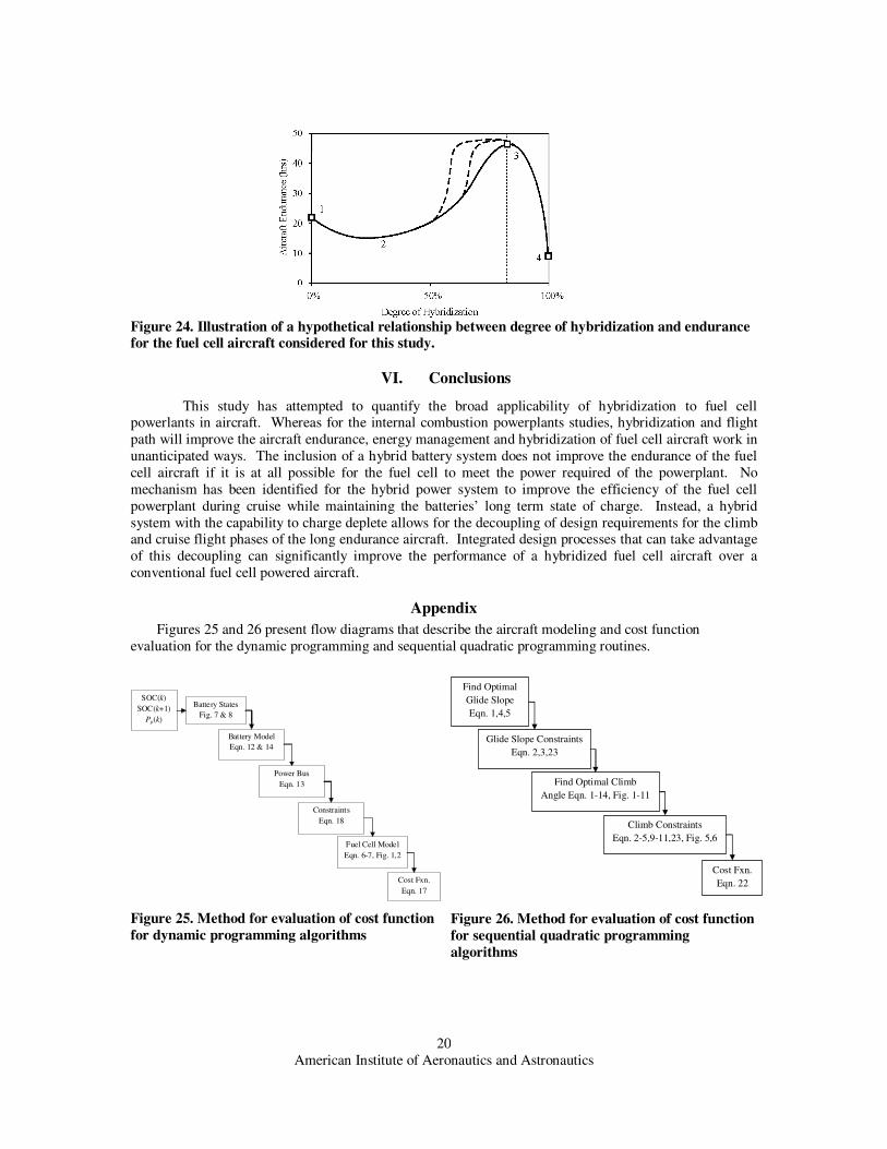
Figure 24 populates the design space shown in Figure 23 with the results of this study and results from
references [11] and [20]. All studies are concerned with a PEM fuel cell powered aircraft with the
characteristics of Table 1. The relationship between degree of hybridization and aircraft endurance is
pinned at points 1, 3 and 4 by the results of this study and [20]. The exact location of the line between the labeled points is hypothetical, but defensible.
Point 1 represents the fuel cell powered aircraft with a degree of hybridization of 0% whose
performance is presented in Table 4. The aircraft at point 1 has an endurance of 22.1hrs. As the
hybridization of this aircraft increases, this study has shown that hybridization has no effect in improving
the endurance of the aircraft. In fact, the lower specific energy of the batteries will have the result of
reducing the specific energy of the aircraft and reducing the maximum endurance of the aircraft. Between
point 1 and point 2, the batteries have no beneficial effect on the endurance of the aircraft. At some point
between point 2 and point 3, the batteries begin to have a beneficial effect. As the degree of hybridization
goes up, the power required of the fuel cell goes down. In turn, the fuel cell becomes less optimized to
meet the takeoff power constraint and becomes more optimized at meeting the high specific energy
requirements. Although the shape of the curve between point 2 and point 3 is highly uncertain (as
represented by the dotted lines), the aircraft performance at point 3 is much improved relative to point 1. At point 3, the fuel cell system is entirely absolved of meeting the takeoff power constraint. With no need
to recharge the batteries, the batteries can be sized to provide most of the takeoff power and then can sit
unused for the remainder of the flight. Table 4 shows that this configuration can lead to a significant
increase in aircraft endurance. Between point 3 and point 4, the aircraft endurance decreases dramatically.
Point 4 is defined at a degree of hybridization of 100%, representing a battery powered aircraft. The lower
specific energy of the battery relative to a fuel cell means that the endurance of the aircraft is much lower
than that of the fuel cell and hybrid aircraft. Reference [20] calculates the endurance of a lithium ion
battery powered aircraft at 9.3 hrs.
Figure 23. Tradeoff between degree of hybridization and power requirements of the fuel cell hybrid
aircraft.
American Institute of Aeronautics and Astronautics
20
Figure 24. Illustration of a hypothetical relationship between degree of hybridization and endurance for the fuel cell aircraft considered for this study.
VI. Conclusions
This study has attempted to quantify the broad applicability of hybridization to fuel cell powerlants in aircraft. Whereas for the internal combustion powerplants studies, hybridization and flight
path will improve the aircraft endurance, energy management and hybridization of fuel cell aircraft work in
unanticipated ways. The inclusion of a hybrid battery system does not improve the endurance of the fuel
cell aircraft if it is at all possible for the fuel cell to meet the power required of the powerplant. No
mechanism has been identified for the hybrid power system to improve the efficiency of the fuel cell
powerplant during cruise while maintaining the batteries’ long term state of charge. Instead, a hybrid
system with the capability to charge deplete allows for the decoupling of design requirements for the climb and cruise flight phases of the long endurance aircraft. Integrated design processes that can take advantage
of this decoupling can significantly improve the performance of a hybridized fuel cell aircraft over a
conventional fuel cell powered aircraft.
Appendix
Figures 25 and 26 present flow diagrams that describe the aircraft modeling and cost function
evaluation for the dynamic programming and sequential quadratic programming routines.
Battery States
Fig. 7 & 8
Battery Model
Eqn. 12 & 14
SOC(k)
SOC(k+1)
Pp(k)
Power Bus
Eqn. 13
Constraints
Eqn. 18
Fuel Cell Model
Eqn. 6-7, Fig. 1,2
Cost Fxn.
Eqn. 17
Figure 25. Method for evaluation of cost function
for dynamic programming algorithms
Find Optimal
Glide Slope
Eqn. 1,4,5
Glide Slope Constraints
Eqn. 2,3,23
Climb Constraints
Eqn. 2-5,9-11,23, Fig. 5,6
Cost Fxn.
Eqn. 22
Find Optimal Climb
Angle Eqn. 1-14, Fig. 1-11
Figure 26. Method for evaluation of cost function
for sequential quadratic programming
algorithms

American Institute of Aeronautics and Astronautics
21
Acknowledgments
This research was funded in part by the NASA University Research Engineering Technology Institute
(URETI) grant to the Georgia Institute of Technology and the Colorado Space Grant Consortium Award to
Colorado State University.
References
[1] Herwerth, C., Chiang, C., Ko, A., Matsuyama, S., Choi, SB., Mirmirani, M., Gamble, D., Arena, A.,
Koschany A., Gu, G., and Wankewycz, T., “Development of a Small Long Endurance Hybrid PEM Fuel Cell Powered UAV,” Society of Automotive Engineers Paper 2007-01-3930, Sep. 2007.
[2] Choi, T.P., Soban D.S., and Mavris, D.N., “Creation of a Design Framework for All-Electric
Aircraft Propulsion Architectures,” AIAA Paper 2005-5549, Aug. 2005.
[3] Choi, T.P., “A recourse-based solution approach to the design of fuel cell aeropropulsion systems,”
PhD Dissertation, Georgia Institute of Technology, 2008.
[4] Qu, Y.C., and Zhao, Y.J., “Energy-Efficient Trajectories of Unmanned Aerial Vehicles Flying
through Thermals,” Journal of Aerospace Engineering, Vol. 18, No. 2, 2005, pp. 84-92.
[5] Menon, P.K., Sweriduk, G.D., Bowers, A.H., “A study of near-optimal endurance maximizing
periodic cruise trajectories,” AIAA Paper 2005-6046, Aug. 2005..
[6] Speyer, J.L., Dannemiller, D., and Walker D., “Periodic Optimal Cruise of an Atmospheric
Vehicle.” Journal of Guidance, Vol. 8, No. 1, pp. 31-38, 1985.
[7] Chen, R.H., and Speyer, J.L., “Improved Endurance of Optimal Periodic Flight,” Journal of
Guidance, Control and Dynamics, Vol. 30, No. 4, 2007, pp. 1123-33.
[8] Youngblood, J., and Talay, T., “Solar powered airplane design for long-endurance, high altitude
flight,” AIAA Paper 1982-0811, May 1982.
[9] Keidel, B., "Auslegung und Simulation von hochfliegenden, dauerhaft stationierbaren
Solardrohnen," PhD Dissertation, Technischen Universität München, 2000.
[10] Phillips, W.F., Mechanics of Flight, John Wiley and Sons, Inc., Hoboken, New Jersey, 2004.
[11] Moffitt, B., Bradley, T.H., Mavris, D., and Parekh, D.E., “Reducing Design Error of a Fuel Cell
UAV through Variable Fidelity Optimization,” AIAA Paper 2007-7793, Sep. 2007.
[12] Bradley, T.H., Moffitt, B., Mavris, D., and Parekh, D.E., “Development and Experimental
Characterization of a Fuel Cell Powered Aircraft,” Journal of Power Sources, Vol. 171, 2007, pp.
793-801. [13] Pukrushpan, J.T., Stefanopoulou, A.G., and Peng, H., Control of Fuel Cell Power Systems, Springer:
2004.
[14] Daberkow, D.D., and Mavris, D.N., “New Approaches to Conceptual and Preliminary Aircraft
Design: A Comparative Assessment of a NN Formulation and RSM”, AIAA Paper 98-5509, Sep.
1998.
[15] Hendrickson, S.P., “A miniature powerplant for very small, very long range autonomous aircraft,”
Insitu Group, Bingen, Washington, 1999.
[16] Moffitt, B A., Bradley, T.H., Parekh, D.E., and Mavris, D. “Vortex propeller model generation and
validation with uncertainty analysis for UAV design.” AIAA Paper 2008-406, Jan. 2008.
[17] Goldstein, S., “On the Vortex Theory of Screw Propellers,” Proceedings of the Royal Society of
London, Series A. Vol. 123, No. 792, pp. 440-495, 1929. [18] Zhang, S.S., Xu K., and Jow, T.R., “Charge and discharge characteristics of a commercial LiCoO2-
based 18650 Li-ion battery,” Journal of Power Sources, Vol. 160, 2006, pp. 1403–1409.
[19] Schmalle III, D.G., Dingus, B.R and Reinholtz, C. “Development and application of an autonomous
unmanned aerial vehicle for precise aerobiological sampling above agricultural fields,” Journal of
Field Robotics Vol. 25, No. 3, 2008, pp. 133–147.
[20] Bradley, T.H., Moffitt, B.A., Mavris, D.N., Fuller, T.F., and Parekh, D.E., “Hardware in the loop
testing of a fuel cell aircraft powerplant,” In press at Journal of Propulsion and Power, 2009.
[21] Moffitt, B., Bradley, T. H., Mavris, D., and Parekh D. E. “Design Space Exploration of Small- Scale
PEM Fuel Cell Long Endurance Aircraft.” AIAA Paper 2006-7701.
[22] Bosch Automotive Handbook, 7th Edition, Society of Automotive Engineers, Warrendale, PA: 2007.
[23] Larminie, J., and Dicks, A., Fuel Cell Systems Explained, 2nd Edition, Wiley, New York, 2003.

American Institute of Aeronautics and Astronautics
22
[24] Sanyo Electric Company Ltd., Lithium Polymer Rechargeable Batteries, Product Literature, October
10, 2002.