Energy Gain from Thermonuclear Fusion S Lee & S H Saw Institute for Plasma Focus Studies INTI...
64
Energy Gain from Thermonuclear Fusion S Lee & S H Saw Institute for Plasma Focus Studies INTI University College, Malaysia Turkish Science Research Foundation Ankara 1 October 2009 -6 pm
-
Upload
maryann-stephens -
Category
Documents
-
view
216 -
download
0
Transcript of Energy Gain from Thermonuclear Fusion S Lee & S H Saw Institute for Plasma Focus Studies INTI...

Energy Gain from Thermonuclear Fusion
S Lee & S H SawInstitute for Plasma Focus Studies
INTI University College, Malaysia
Turkish Science Research Foundation Ankara 1 October 2009 -6 pm

Content
• Thermonuclear fusion reactions
• Energy gain per D-T reaction; per gm seawater
• Cross sections vs beam energies & temperatures
• IIT, ntT criteria
• Progress up to 2009
• ITER, DEMO
• Other schemes: Inertial, Pinches

STARS:- Nature’s Plasma Fusion Reactors
Whilst above the white stars quiver
With nuclear fusion burning-bright!

Tokamak-planned nuclear fusion reactor

Natural Fusion Reactors vsFusion Experiments on Earth

Introductory: What is a Plasma?
Four States of Matter
SolidLiquidaseousPlasma
Four States of Matter SOLID LIQUID GAS PLASMA
Matter heated to high temperatures
becomes a Plasma

Characteristics of Plasma State• Presence of electrons and ions• Electrically conducting• Interaction with electric & magnetic fields• Control of ions & electrons: applications• High energy densities/selective particle energies
-Cold plasmas: several eV’s; (1eV~104K) -Hot plasmas: keV’s ; (1keV~107K)• Most of matter in Universe is in the Plasma State
(e.g. the STARS)

Major technological applications
• Surface processing, cleaning, etching, deposition• Advanced materials, diamond/CN films• Environmental e.g.waste/water treatment• High temperature chemistry• MHD-converters, thrusters, high power switches• Radiation sources: Microelectronics lithography• Medical: diagnostics, cleaning, instrumentation• Light sources, spectroscopic analysis, FP displays • Fusion Energy

The Singular, arguably Most Important Future Technological Contribution, essential to Continuing Progress of Human Civilization:-
A NEW LIMITLESS SOURCE OF ENERGY

Scenario: World Population stabilizes at 10 billion; consuming energy at 2/3 US 1985 per capita rate
Fossil, Hydro, fission
Consumption
Supply
Shortfall

Plasma Fusion (CTR) & the Future of Human Civilization
A new source of abundant (limitless) energy is needed for the continued progress of human civilization.
Mankind now stands at a dividing point in human history:
•200 years ago, the Earth was under-populated with abundant energy resources
•100 years from now, the Earth will be over-crowded, with no energy resources left

Without a new abundant source of energy
Human civilization cannot continue to flourish.
Only 1 good possibility:
Fusion (CTR) Energy from Plasma Reactors

Collisions in a Plasma
The hotter the plasma is heated, the more energetic are the collisions

Nuclear Fusion
If a Collision is sufficiently energetic, nuclear fusion will occur

Isotopes of hydrogen- Fuel of Fusion

Release of energy in Fusion

Conversion of mass into Energy

Fusion Energy Equivalent
50 cups water
• 1 thimble heavy water, extracted from 50 cups of water

• One litre of water contains 30mg of deuterium. If fully burned in fusion reactions, the energy output would be equivalent to 300 litres of gasoline.
• Equivalent to filling the Atlantic and Pacific oceans 300 times with gasoline.
• Would satisfy the entire world's energy needs for millions of years.
• Fusion can also produce hydrogen which may be useful for transportation.
Fusion Energy Equivalent

Energy-Demand and Supply: 3% demand scenario
Supply able to match demand up to critical point of time
Supply unable to match demand without new source
Fusion Energy

1Q=1018 BTU~1021Jestimates: various sources (conservative)
World consumption per year:
1860: 0.02Q
1960: 0.1 Q
1980: 0.2 Q
2005: 0.5Q
Doubling every 20-30 years into the future (depending on scenario)

• Coal: 100Q• Oil: 10Q• Natural gas: 1 Q• Fission: 100Q• Low grade ore for fission (economic?): 107 Q• D-T fusion (Li breeding): 100Q• D-T fusion (low grade Li economic?): 107 Q
• Fusion deuterium> 1010 Q
1Q=1018 BTU~1021JWorld reserves: -H R Hulme

Cross sections for D-T, D-D reactions- 1 barn=10-24 cm2;1 keV~107K
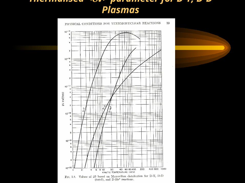
Thermalised <v> parameter for D-T, D-D Plasmas

Power densities for D-T, D-D reactions and Bremsstrahlung defining Ideal Ignition Temperatures- for 1015 nuclei cm-3
Mean free paths and mean free times in fusion plasmas
• These have also to be considered, as at the high temperatures, the speeds of the reactons are high and mfp of thousands of kms are typical before a fusion reaction takes place.
• Such considerations show that at 10 keV, the plasma lifetime (containment time) has to be of the order of 1 sec for a density of 1021 m-3
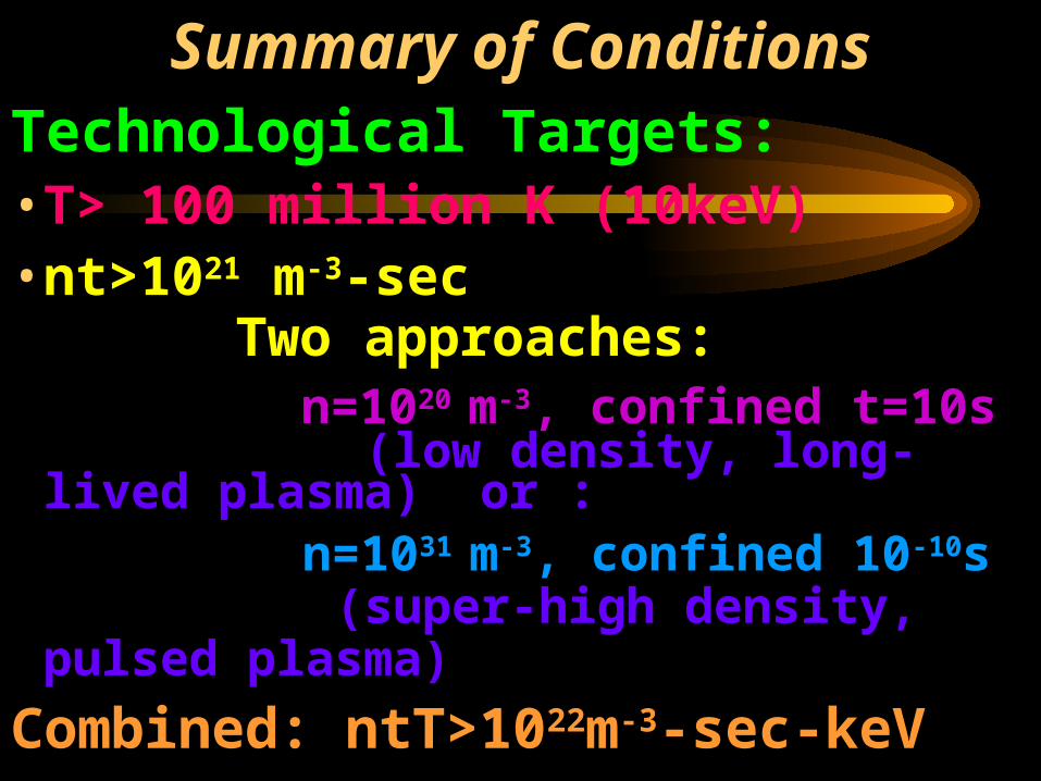
Summary of Conditions
Technological Targets:• T> 100 million K (10keV)• nt>1021 m-3-sec Two approaches: n=1020 m-3, confined t=10s
(low density, long-lived plasma) or : n=1031 m-3, confined 10-10s
(super-high density, pulsed plasma)
Combined: ntT>1022m-3-sec-keV

Containing the Hot Plasma
Continuous Confinement
Long-lived low-density Confinement
Pulsed High Density Confinement

Low Density, Long-lived Approach (Magnetic Compression)
Tokamak• Electric currents for heating
• Magnetic fields in special configuration for stability

Schematic of Tokamak

Magnetic Yoke to induce Plasma Current
Field Coils to Produce suitable Magnetic Field Configuration

JET (Joint European Torus)
• Project successfully completed January 2000

Inside JET

JET X-Section

Energy confinement time t scales as some functions of:
• Plasma current Ip• Major Radius R• Minor radius ‘a’• Toroidal Magnetic Field B
scaling law: t~IpRaB
indicesare all positive
To achieve sufficient value of ntT requires:
scaling of present generation of Tokamaks upwards in terms of:
Ip, R, ‘a’ and B.

Fusion Temperature attained Fusion confinement one step away

International Collaboration to develop Nuclear Fusion Energy-ITER
• 1985- Geneva Superpower Summit:• Reagan (US) & Gorbachev (Soviet Union)
agreed on project to develop new cleaner, sustainable source of energy- Fusion energy
• ITER project was born• Initial signatories: former Soviet Union, USA,
European Union (via EURATOM) & Japan• Joined by P R China & R Korea in 2003 & India
2005• ITER Agreement- signed in November 2006

ITER (International Thermonuclear Experimental Reactor)

ITER Construction has now started in Cadarache, France
First plasma planned 2018First D-T planned 2022

Q>10 and BeyondITER : to demonstrate: possible to produce commercial energy from fusion.
Q= ratio of fusion power to input power. Q ≥ 10 represents the scientific goal of ITER :
to deliver 10x the power it consumes. From 50 MW input power to 500 MW of fusion power - first fusion experiment to produce net energy.
Beyond ITER will be DEMO (early 2030’s), demonstration fusion power plant which will put fusion power into the grid as early as 2040

FIRE: Incorporates Many Advanced Features

Potential Next Step Fusion Burning Experiments

The other approach: Pulsed Super-high Density
(Inertial Compression)
•Radiation Compression

Pulsed Fusion: Radiation Compression
• Radiation Pressure Compression: Ignition: Burn:
• e.g. powerful lasers fuel is compressed by density of fuel core Thermonuclear fusion
• beamed from all rocket-like blow-off of reaches 1000 times spreads rapidly through
• directions onto D-T hot surface material density of water super-compressed fuel
• pellet (0.1mm radius) & ignites yielding many times
• at 100 million K input energy

Cross-sectional view of the KOYO-F fast ignition reactor (Norimatsu et al.)

Large scale Fusion Experiments
• Tokamaks: Low density, long confinement plasmas
• Laser Implosions: Super-dense, sub-nanosecond plasmas
Smaller scale Fusion ExperimentsPinches: Dense, microsecond plasmas

Introduction• Plasma Focus (PF)-
– remarkably copious source of multiple radiation: x-rays, fast electrons, ions and plasma stream
– Fusion neutrons demonstrated even in table top devices
– same energy density at storage energy levels of 0.1-1000 kJ; hence scalability of neutrons

Superior method for dense pinches
• The PF produces suitable densities and temperatures.
• A simple capacitor discharge is sufficient to power the plasma focus.

THE PLASMA FOCUS (PF)
• The PF is divided into two sections.
• Pre-pinch (axial) section: Delays the pinch until the capacitor discharge current approaches peak value.
• The pinch starts & occurs at top of the current pulse.

The Plasma Dynamics in FocusThe Plasma Dynamics in Focus
HV 30 F, 15 kV
Inverse Pinch Phase
Axial Accelaration Phase
Radial Phase

Radial Compression (Pinch) Phase of the Plasma Focus

High Power Radiation from PF
• powerful bursts of x-rays, ion beams, REB’s, & EM radiation (>10 gigaW)
• Intense radiation burst, extremely high powers
• E.g. SXR emission peaks at 109 W over ns
• In deuterium, fusion neutrons also emitted

Same Energy Density in small and big PF devices leads to:
• Scalability– constant speed factor, [(I/a)/1/2] for all machines,
big or small lead to same plasma energy density
• from 0.1 to 1000 kJ of storage energy– predictable yield of radiation

One of most exciting properties of plasma focus is its neutron yield Yn
• Early experiments show: Yn~E02
• Prospect was raised in those early research years that, breakeven could be attained at several tens of MJ .
• However quickly shown that as E0 approaches 1 MJ, a
neutron saturation effect was observed; Yn does not increase as much as expected, as E0 was progressively raised towards 1 MJ.
• Question: Is there a fundamental reason for Yn saturation?

Chart from M Scholz (November 2007 ICDMP)

Yn ‘saturation’ observed in numerical experiments (solid line) compared to measurements on various machines (small squares) -IPFS

Comparing generator impedance & Dynamic Resistance DR0 of small & large plasma focus- before Ipeak
Axial Axial Ipeak
PF Z0 =(L0/C0)1/2 DR0 dominance
Small 100 mmZ0 V0/Z0
Large 1 mmDR0V0/DR0
As E0 is increased by increasing C0, with voltage kept around tens of kV, Z0 continues to decrease and Ipeak tends towards asymptotic value of V0/DR0

Confirming Ipeak saturation is due to constancy of DR0
Ipeak vs E0 from DR0 analysis compared to model simulation
Model simulation gives higher Ipeak due to a ‘current overshoot effect’ which lifts the value of Ipeak before the axial DR0 fully sets in
Ipeak vs E0 on log-log scale
DR0 analysis
Confirming that Ipeak scaling tends to saturate before 1 MJ
y = 228x0.48
y = 1923x0.08
100
1,000
10,000
0 10 1000 100000
E0 in kJ
Ipe
ak
in
kA
Ipeak, Low E0
Ipeak, High E0
Ipeak, Mid E0
Power (Ipeak,Low E0)Power (Ipeak,High E0)

At IPFS, we have shown that: constancy of DR0 leads to current ‘saturation’ as E0 is increased by increasing
C0. Tendency to saturate occurs before 1 MJ
From both numerical experiments as well as from accumulated laboratory data:
• Yn~Ipinch4.5
• Yn~Ipeak3.8
Hence the ‘saturation’ of Ipeak leads to saturation of neutron yield Yn

Insight- neutron saturation
• A major factor for ‘neutron saturation’ is simply: Axial Phase Dynamic Resistance

Conclusions and Discussion Beyond saturation?
Possible ways to improve Yn: • Increase operating voltage. Eg SPEED II uses Marx technology: 300kV,
driver impedance 60 m. With E0 of under 200 kJ, the system was designed to give Ipeak of 5 MA and Ipinch just over 2 MA.
• Extend to 1MV-with low bank impedance- would increase Ipeak to 100 MA; at several tens of MJ. Ipinch could be 40 MA
• Yn enhancing methods such as doping deuterium with low % of krypton.
• Further increase in Ipinch by fast current-injection near the start of radial phase. This could be achieved with charged particle beams or by circuit manipulation such as current-stepping. This model is ideally suited for testing circuit manipulation schemes.

Ongoing IPFS numerical experiments of Multi-MJ, High voltage MJ and Current-step Plasma Focus

Conclusion:
• Tokamak programme is moving steadily towards harnessing nuclear fusion energy as a limitless clean energy source for the continuing progress of civilisation
• Alternative and smaller scale experiments will also play a role in this most challenging technological development

THANK YOU Appreciation to the following web-sites:
• http://fusion.gat.com• http://chandra.harvard.edu• http://fire.pppl.gov• http://www.jet.efda.org• http://www.iter.org• http://www.fusion.org.uk• http://www-jt60.naka.jaeri.go.jp
• http://www.hiper-laser.org/ • http://www.intimal.edu.my/school/fas/UFLF• http://www.plasmafocus.net