Energy from the sea for seagoing vessels - Maritime...
29
Rotterdam Mainport University of Applied Sciences - RMU Energy from the sea for seagoing vessels Igor Donker Philip van Herwaarden Léon Stuurman Otto van Zutphen
Transcript of Energy from the sea for seagoing vessels - Maritime...

Rotterdam Mainport University of Applied Sciences - RMU
Energy from the sea for seagoing vessels
Igor Donker Philip van Herwaarden Léon Stuurman Otto van Zutphen

1
Preface This project started in September 2009 as a school assignment. We were free to choose a direction and we came up with propulsion and auxiliary engines. From our principle we had to choose a subject. At first we had no idea what we had to investigate, however after a week we had an idea; How can energy be gained from the sea, and is it possible to use this in the maritime industry in any way? The first weeks we all did a lot of desk research on the subject and found out that there is a lot of ideas about how to gain energy from the sea. We wanted to know if you can generate energy, while making use of the tidal streams, waves and the difference in potential between salt water and fresh water. We chose these subjects because the shipping industry is a big polluter of CO2. All of the investigated subjects do not emit CO2, sulphur or soot particles, which is good for the environment and will contribute to a greener image of the shipping industry. We have learned from this project that a proper planning is essential for a good work climate and that it is important to have good communications between group members. We want to thank Mr. Van Kluijven, Mr. Naudts and Mr. Veldhoedt for their comments and directions.
Rotterdam, January 25th 2010 Project Group P&A2 Igor Donker Philip van Herwaarden Léon Stuurman Otto van Zutphen

2
Table of contents 1. Introduction .................................................................................................................................................... 3
1.1 Background ............................................................................................................................................ 3 1.2 Objectives .............................................................................................................................................. 3 1.3 Project borders ...................................................................................................................................... 4 1.4 Structure ................................................................................................................................................ 4
2. Wave energy ................................................................................................................................................... 5 2.1 Introduction ........................................................................................................................................... 5 2.2 Types of Wave Energy ........................................................................................................................... 5 2.3 Wave Energy Converter ......................................................................................................................... 6 2.4 Wavegen Energy Converter ................................................................................................................... 8 2.5 Wave energy applications on seagoing vessels ................................................................................... 10
3. Tidal energy .................................................................................................................................................. 12 3.1 Introduction ......................................................................................................................................... 12 3.2 Types of tidal energy converters ......................................................................................................... 12 3.3 Energy from the difference in tides ..................................................................................................... 12 3.3.1 Working principle ..................................................................................................................................... 12 3.3.2 Examples currently in use ........................................................................................................................ 13 3.3.3 Applications in the Netherlands ............................................................................................................... 15 3.4 Tidal current energy ............................................................................................................................ 15 3.4.2 Applications in the Netherlands .......................................................................................................... 17 3.4.3 Tidal reefs ............................................................................................................................................ 17 3.5 Application on seagoing vessels .......................................................................................................... 18
4. Blue energy ................................................................................................................................................... 19 4.1 Pressure retarded osmosis (PRO) ........................................................................................................ 19 4.2 Reverse electro dialysis (RED) .............................................................................................................. 21 4.3 Application of both PRO and RED on seagoing vessels ....................................................................... 23
5. Conclusions and recommendations ............................................................................................................. 24 5.1 Conclusions and recommendations on wave energy .................................................................................. 24 5.2 Conclusions and recommendations on tidal energy ................................................................................... 25 5.3 Conclusions and recommendations on blue energy ................................................................................... 26 5.4 Comparison of the different methods ........................................................................................................ 26
6. References .................................................................................................................................................... 27

3
1. Introduction
1.1 Background
In the world today, there is an ever-growing need for green energy. Fossil fuels are running out and the emission of greenhouse gas are harmful to the future of our planet. The maritime industry is one of the largest emitters of carbon dioxide in the world. To not only reduce pollution in the maritime industry, but also to innovate the industry by making it more profitable, we have looked for ways to incorporate the concept of green energy into the shipping industry (with a preference for application onboard seagoing vessels). One gigantic potential energy source is the sea itself, on which all seagoing vessels sail. The sea is in constant motion, waves forming, currents, tidal streams, etc. etc. If seagoing vessels were in any way able to use this energy, a lot of money can be saved and the environment will be spared, for it would mean free energy as well as a reduction in carbon dioxide emissions. Nowadays, a lot of ways of gaining energy from the sea, or any kind of water, are in development. Yet others have already been used for decades. The blue energy that will be discussed in this report is a less known form of green energy, however its potential is enormous. For example the potential energy of the tidal currents along the Dutch coast is, at any given time, enough to power every household in the Netherlands for one year. There is a lot of potential energy in the sea, getting it out so that it can be used properly is a challenging subject but none the less we wanted to research if, and how seagoing vessels can benefit from this technology in any way.
1.2 Objectives
The main objective of this report is to present our research concerning energy from the sea. The research was performed to find an answer to the main research question: How can energy be gained from the sea, and is it possible to use this in the maritime industry in any way ? This is a very broad question to give answer to as there are so many ideas on how to gain energy from the sea. The main focus will be on seagoing vessels, and ways to gain power for their propulsion and auxiliary systems. It is not the intention to come up with our own inventions so the research has been restricted to three forms of energy from the sea. These three possible energy sources in the sea form the core of the sub-questions of this research report: How can energy be gained from the waves, and is it possible to use this in the maritime industry? How can energy be gained from the tides, and is it possible to use this in the maritime industry? How can energy be gained from the difference in potential between fresh and salt water, and how can this be used in the maritime industry ?

4
In this report each of the three sub-questions will be answered as complete as possible. To do this, the following topics will be discussed for each separate method:
A short history on the subject
Technical information on how it works, or should work
Description of applications already in use
Possible applications onboard seagoing vessels and related equipment
Advantages of the described methods
Disadvantages of the described methods
Problems and solutions concerning the described methods All the research findings will eventually be compared with each other so that a conclusion can be drawn onto the best way to use energy from the sea for seagoing vessels.
1.3 Project borders
This project is about ways to use energy from the sea for seagoing vessels. It will only address, wave, tidal and blue energy.
Although the main focus is on seagoing vessels, applications for uses on land may also have been researched. This in possible relation to shore power.
When addressing the issue of shore power connection, only Dutch ports will be researched for ways of using water energy for this purpose.
It was never the intention to come up with a new way of gaining energy from the sea.
This project will only focus on gaining energy from the sea for direct or indirect power delivery to propulsion and auxiliary systems on board
1.4 Structure
To give an answer to the main question of this report, chapter 2, 3 and 4 will give a comprehensive explanation on the three researched subjects. Chapter 2 will be a report on all findings concerning wave energy. Chapter 3 will do the same for tidal energy and Chapter 4 will explain all about blue energy. Each of these chapters will contain possible ways to use the technology onboard or relating to seagoing vessels. In chapter 5, the conclusions and recommendations, all three methods will be compared against each other so that the possibilities of all three methods in the future can be mapped out properly.

5
2. Wave energy 2.1 Introduction
Wave Energy is energy that is produced by the motion of waves. This form of energy generation was invented recently, and there is still a lot of research to do. Currently there are wave energy converters in the trial phase in more locations. Wave energy contributes to a better environment, this is because there are no emissions. There are no greenhouse gases, and that is good for the environment. Wave energy is really another form of wind energy, because waves are produced by wind. This energy is easy to catch, and it is better then when we use fossil fuels and our consumption, which are bad for the environment. This energy is a new source of energy, and it overcomes fossil fuels, because this type of energy generation is very attractive. The types of wave energy that we will treat all based on the same system. There are several ways of generating energy by waves. Wave energy has advantages and there are also some disadvantages, which are also described. Finally, we highlight applications to seagoing vessels, which are already applied to small vessels. Wave energy will certainly find more applications in the near future 2.2 Types of Wave Energy There are several different types of wave powered generators. You would not think, simply because waves are waves. The difference exists in the location where the power of the waves is captured. We describe wave energy into two distinct categories. - Wave energy at sea - Wave energy at the embankment. Wave energy at sea means that the wave energy generators float in the sea, and that the energy is generated by an interconnected network which than sends the energy to a receiver. This type of wave energy is very interesting, because we ultimately want a ship that has no emissions. As waves move alongside the ship, the ship should be able to obtain (clean) energy from it. Wave energy at the embankment means that the generator is built on the mainland, and the waves will stop there. This type of wave energy is also interesting, because this technique is practical, and relatively inexpensive. These two types of wave energy are again divided into the different types of wave energy, because they are implemented in many different forms. We will explain one type of both kinds of wave energy, because they all function in similar ways. Wave energy at sea There are a lot of different ways to gain energy from waves, however they all have one thing in common: all the wave energy generators gain their energy from moving parts driven by waves. There are currently several places in the world where wave energy fields are being built at this time, this is a huge project. The company whose technique we researched is Pelamis Wave Energy. This company is currently the most advanced in the field of collecting Wave Energy.
6
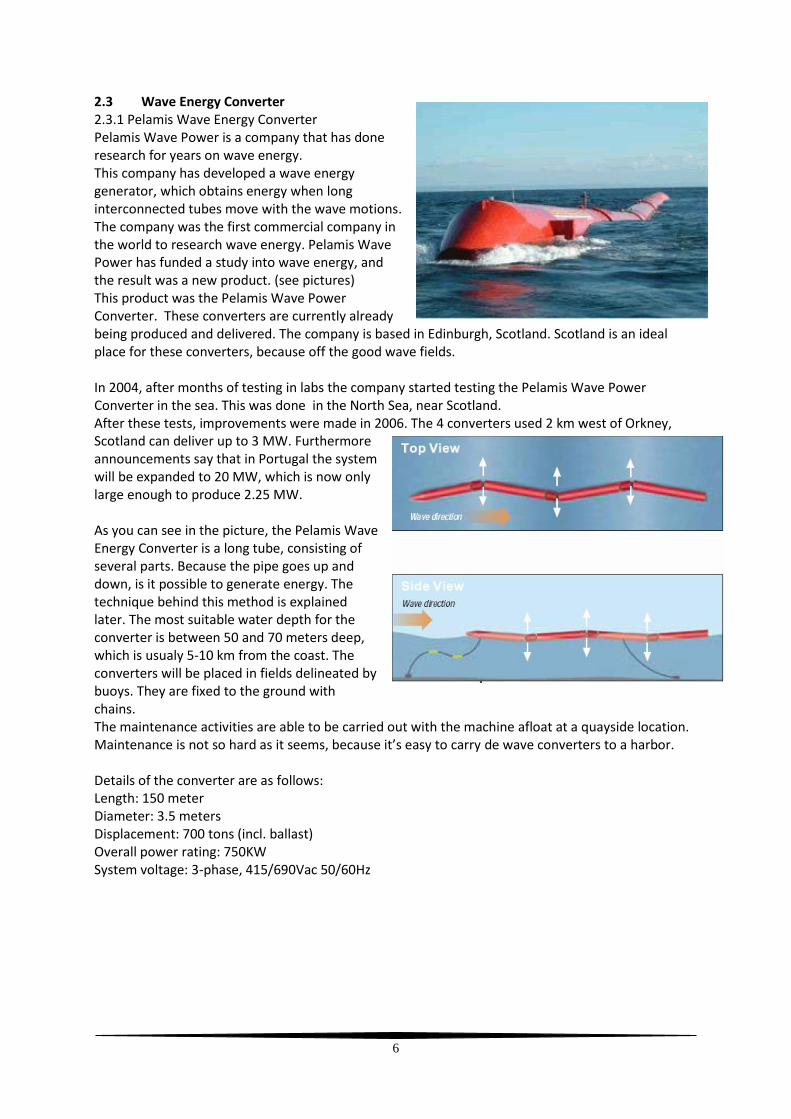
2.3 Wave Energy Converter 2.3.1 Pelamis Wave Energy Converter Pelamis Wave Power is a company that has done research for years on wave energy. This company has developed a wave energy generator, which obtains energy when long interconnected tubes move with the wave motions. The company was the first commercial company in the world to research wave energy. Pelamis Wave Power has funded a study into wave energy, and the result was a new product. (see pictures) This product was the Pelamis Wave Power Converter. These converters are currently already being produced and delivered. The company is based in Edinburgh, Scotland. Scotland is an ideal place for these converters, because off the good wave fields. In 2004, after months of testing in labs the company started testing the Pelamis Wave Power Converter in the sea. This was done in the North Sea, near Scotland. After these tests, improvements were made in 2006. The 4 converters used 2 km west of Orkney, Scotland can deliver up to 3 MW. Furthermore announcements say that in Portugal the system will be expanded to 20 MW, which is now only large enough to produce 2.25 MW. As you can see in the picture, the Pelamis Wave Energy Converter is a long tube, consisting of several parts. Because the pipe goes up and down, is it possible to generate energy. The technique behind this method is explained later. The most suitable water depth for the converter is between 50 and 70 meters deep, which is usualy 5-10 km from the coast. The converters will be placed in fields delineated by buoys. They are fixed to the ground with chains. The maintenance activities are able to be carried out with the machine afloat at a quayside location. Maintenance is not so hard as it seems, because it’s easy to carry de wave converters to a harbor. Details of the converter are as follows: Length: 150 meter Diameter: 3.5 meters Displacement: 700 tons (incl. ballast) Overall power rating: 750KW System voltage: 3-phase, 415/690Vac 50/60Hz

7
2.3.2 Power Supply
What we can see in this diagram is the power produced by a significant wave height We clearly see that the generator in a wave height of about 5.5 meters delivers approximately 750 kW. This makes clear that wave fields are needed to reach a large amount. Waves are not constant, therefore the energy generation is also not constant. In this diagram we can see why the energy generated cannot go to users immediately. This is because the supply is too irregular. The current would be supplied with too many power fluctuations. Because a constant power supply is required by users a direct connection is not a solution. To compensate for the power fluctuations a hydraulic buffer installed. Because of this a requirement is that the pressure does not become too high, and if the pressure does get too high the pressure is buffered, this buffer will then release the stored pressure to be released when the pressure drops. This gives the results shown in the following graphic. These power fluctuations are a lot smaller end are more acceptable. What we can see now is that the power peaks are lower than in the previous graph, but it is better distributed and deliverable.

8
2.3.3 Working of the Pelamis Wave Energy Converter. The converter consists of several long cylindrical parts, which are connected together with a hinge. When the tube parts move, an angle will be created between the two parts, and these forces will be transferred into the hydraulic rams. This creates a pressure that is converted into a rotating force. The hydraulic rams build pressure, which is transferred to a hydraulic pump. However, if the pressure gets too high it will be temporarily stored in a buffer, to be used when the pressure drops. This hydraulic power will be delivered to the generator, which supplies power. These converters are composed of 7 parts. Because the motions they make are not all vertically alligned, they can also move horizontal to prevent damage to the converter. The power is supplied to a network, from which power can be taken to provide energy were needed at a voltage of 6,6 kV. 2.3.4 The prices of electricity generated by the Pelamis Wave Converter are not clearly found. After a long investigation which was completed in 2007, the following information is known. Prices depend very much on the cost of the materials required to build the wave converter. The prices of the current that will be delivered, are variable by location. Theories suggest that the price of the energy will be around 0.20 Euro / kWh. However researchers claim that to make sure that no financial loss is created a price of 0.30 Euro / kWh must be expected. The study also showed that in winter the wave energy converter will provide the most energy at the Irish coast. There are also disadvantages to this converter, however these don’t exceed the benefits. The following is a list of advantages and disadvantages, starting with the advantages: - Existing technology, no experimental technology - Cheapest kWh production - High efficiency Disadvantages are: - Cannot be placed everywhere, because it requires accurate waves - No local maintenance possible 2.3.3 Wave energy at the embankment. Wave energy at the embankment is also a feasible way of obtaining energy. This is because this form of gaining energy needs less consideration for the direction of the waves. There are several manufacturers that produce this type of converter. These converters operate almost the same everywhere. Seawater generates a pressure, and this pressure is converted into a rotating motion, which can then drive a turbine. 2.4 Wavegen Energy Converter
One of the manufacturers of these converters is Wavegen. Wavegen is a Scottish company, based in Inverness, Scotland. The company has 2,500 employees and is the largest in its segment. The company started in 1990. They have spent years for improving the converters. Since 2005 Wavegen is the center for wave energy with Voith Hydro. Since November 2000 Wavegen has delivered power to the national grid. This happens on Islay, a small island off the Scottish coast.

9
The converter that is designed by Wavegen is based on air-pressure that is generated by waves. The waves roll in (as you can see the picture) in the collector. This collector is completely closed, and by a huge wave of water mass, the pressure will increase. The airflow which is obtained by the pressure passes through a turbine to leave. This turbine generates electricity. We call this phenomenon also oscillating water column (OCW). The depth of the wave generator is often around 7 meters. The performance has been optimized for annual average wave intensities of between 15 and 25kW / m. The water column feeds a pair of counter-rotating turbines, each of which drives a 250kW generator, giving a nameplate rating of 500kW. Currently the technique is still being improved, by optimizing the turbine. This is done by varying the pitch of the turbine propeller blades to produce an optimal amount of power. The current that will be delivered has a voltage of 400 volts, with a deviation of 10%. The turbine runs up to 1500 rpm, 1016 rpm normal average. Both generators deliver 500 kW, that’s 250 kW each. There is nothing to write about costs, because we cannot find anything about it. 2.4.1 Maintenance The wavegen generator needs very infrequent maintenance. However, it is important that this maintenance is done, to guaranty a long generator life. Because there are a lot of moving parts in the wavegen generator, these parts need maintenance in the form of lubrication. The generator has grease reservoirs to lubricate the bearings of the generator, this grease is replaced every 8000 running hours, the grease of the butterfly valve bearings is replaced each half year. What happens is a weekly general checkup of the system, and the draining of the air compressor. This generator also has advantages and disadvantages. The advantages here simply ranged:. - Reliable - Simple and robust - No hydraulics - No gearbox The disadvantages are that the generator cannot be built anywhere along the Dutch coast, because the appropriate heights and wave fields are required. Another disadvantage is that a constant speed turbine is required, to maintain the same effectiveness.

10
2.5 Wave energy applications on seagoing vessels
Wave energy research on ships is a modern subject. If this is possible in the future, then it will be a major progress in the shipping industry. Several experiments are being conducted to see if it is possible to sail without fossil fuel. We think that it is possible for a ship to continue moving through the energy from waves. Currently in Japan there is a 69-year-old man who has designed a catamaran that has neither engine nor sails, but moves by the energy of waves. This Japanese would like to travel over the world by sailing 4350 Miles. This is a voyage from Hawaii to Japan. This technique is still not applicable to really big ships, however it is applicable to smaller type vessels, which are then completely green energy propelled. The ship moves because the flaps move up and down in a dolphin-like motion. This causes the ship to move forward. It does not matter from where the waves come, but the speed is limited 5 knots. The fins are connected to a spring, which keep the fin in the right position. Because this method of energy generation delivers no electrical power, this boat also needs solar panels, to feed the navigational computer and other electrical consumers. Another example is the design of the ship "Orcelle 'of the Scandinavian company Wallinson Wilhelmson, full speed with clean energy. This ship utilizes both solar energy and wave energy. The solar panels are placed on the sails, and propulsion is the same as the method described above. This ship, like the catamaran from the Japanese has fins under the ship as propulsion. Because the movement of these fins is similar to that of a dolphin the ship was named Orcelle, which is a dolphin species. The ship is less than 250 meter long, and will be able to transport 10,000 vehicles The cruise speed of this ship is 15 knots, with a top speed of 27 knots. We will have to wait several years before this ship really exists however. Mentioned dates are all around 2025. It should be possible to catch the waves without creating additional resistance.

11
This could be by using stabilizers, which are connected to a generator. When the ship lists, the stabilizers are pushed up or pulled down, allowing the hydraulic rams to be pushed or pulled. This creates a pressure, which can be converted into electricity. As a ship is not always listing, the stabilizers are not always able to provide energy. Therefore more energy sources on board vessels are needed in order to meet the required capacity. However, cruise and passenger ships always use stabilizers during the trip. These could be linked so that they produce energy instead of just costing energy in the form of resistance. It is probably possible to build the wave energy generator from Wavegen into ships. It is probably not always profitable while under way. However if the ship is anchored, than it can be profitable to use these generators as an extra power source. There is still much research on what is possible with wave energy. As described above, there is a draft of a ship fully sailing on 'green' energy. This design will only improve in the future.

12
3. Tidal energy
3.1 Introduction
The tides are the rise and fall of the sea level. This motion contains potential energy. The largest tidal energy plant was built in France in 1965 it is still operational and produces 540 GWh/year with a price of € 0,03 KWh. There is still a lot of research going on and there are tidal energy generation fields planned in the UK, Canada and South Korea. The Dutch government is also interested in this kind of green power since we have to look for other kinds of energy sources which are carbon emission free. With fossil fuels running out and global warming threatening the climate it is good to know that there are other forms of energy which are environment friendly. Rotterdam is one of the major ports in the world and has the ambition to have a net zero carbon footprint in 2012. One of the ideas to accomplish this is to use shore power for vessels that are in port; This is being tested by Stena Line. To generate energy with no carbon emission tidal energy has potential, with an estimated length of 250 kilometers and an average depth of 20 meter and a current of 1 m/s. The theoretical energy supply along the Dutch coastline is 22 TWh. There are several ways to catch this energy. With all restrictions a respectable 1.39 TWh is feasible.
3.2 Types of tidal energy converters There are several ways to convert tidal energy into electric energy. The difference is to get the energy from the difference in the tide or make use of the tidal currents. Tidal power can be divided into two categories. • Tidal range technologies exploiting the difference in water level between high and low tides. • Tidal stream technologies exploiting the fast-moving water found in channels and around some parts of the coastline. Both types of tidal power are being researched at this moment and a new tidal energy converter called a tidal reef has made its way to the drawing board.
3.3 Energy from the difference in tides A power plant that uses the difference in tides is call a barrage tidal power generator. This kind of construction is used in France, it’s also being researched in Russia, Canada and China. The difference in the rise and fall of the seawater in La Rance is 8 meters with a maximum of 13.5 meters. A study to apply this technology into the Oosterschelde turned out negative because of the ecological problems that will occur. Tidal range technology is only feasible in places where the difference in tide level is 7 meters or more. 3.3.1 Working principle To gain energy from hydraulic fall and rising of water a basin is needed. In this example the basis is separated by the sea using a dam like construction. When there is high water, the water level on the sea side will increase and will be higher than the water level in the basin. The water pressure on the sea side will be higher thus it will flow through the dam powering a turbine as it goes. At a certain point in time the level in the basin will be the same as the sea level, now no water will flow through the turbine.
13
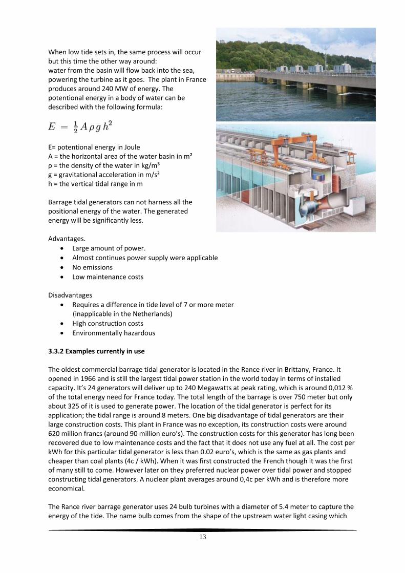
When low tide sets in, the same process will occur but this time the other way around: water from the basin will flow back into the sea, powering the turbine as it goes. The plant in France produces around 240 MW of energy. The potentional energy in a body of water can be described with the following formula:
E= potentional energy in Joule A = the horizontal area of the water basin in m² ρ = the density of the water in kg/m³ g = gravitational acceleration in m/s² h = the vertical tidal range in m Barrage tidal generators can not harness all the positional energy of the water. The generated energy will be significantly less. Advantages.
Large amount of power.
Almost continues power supply were applicable
No emissions
Low maintenance costs
Disadvantages
Requires a difference in tide level of 7 or more meter (inapplicable in the Netherlands)
High construction costs
Environmentally hazardous 3.3.2 Examples currently in use The oldest commercial barrage tidal generator is located in the Rance river in Brittany, France. It opened in 1966 and is still the largest tidal power station in the world today in terms of installed capacity. It’s 24 generators will deliver up to 240 Megawatts at peak rating, which is around 0,012 % of the total energy need for France today. The total length of the barrage is over 750 meter but only about 325 of it is used to generate power. The location of the tidal generator is perfect for its application; the tidal range is around 8 meters. One big disadvantage of tidal generators are their large construction costs. This plant in France was no exception, its construction costs were around 620 million francs (around 90 million euro’s). The construction costs for this generator has long been recovered due to low maintenance costs and the fact that it does not use any fuel at all. The cost per kWh for this particular tidal generator is less than 0.02 euro’s, which is the same as gas plants and cheaper than coal plants (4c / kWh). When it was first constructed the French though it was the first of many still to come. However later on they preferred nuclear power over tidal power and stopped constructing tidal generators. A nuclear plant averages around 0,4c per kWh and is therefore more economical. The Rance river barrage generator uses 24 bulb turbines with a diameter of 5.4 meter to capture the energy of the tide. The name bulb comes from the shape of the upstream water light casing which
14
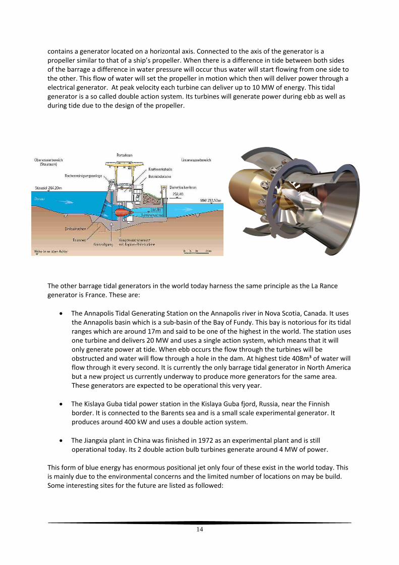
contains a generator located on a horizontal axis. Connected to the axis of the generator is a propeller similar to that of a ship’s propeller. When there is a difference in tide between both sides of the barrage a difference in water pressure will occur thus water will start flowing from one side to the other. This flow of water will set the propeller in motion which then will deliver power through a electrical generator. At peak velocity each turbine can deliver up to 10 MW of energy. This tidal generator is a so called double action system. Its turbines will generate power during ebb as well as during tide due to the design of the propeller.
The other barrage tidal generators in the world today harness the same principle as the La Rance generator is France. These are:
The Annapolis Tidal Generating Station on the Annapolis river in Nova Scotia, Canada. It uses the Annapolis basin which is a sub-basin of the Bay of Fundy. This bay is notorious for its tidal ranges which are around 17m and said to be one of the highest in the world. The station uses one turbine and delivers 20 MW and uses a single action system, which means that it will only generate power at tide. When ebb occurs the flow through the turbines will be obstructed and water will flow through a hole in the dam. At highest tide 408m³ of water will flow through it every second. It is currently the only barrage tidal generator in North America but a new project us currently underway to produce more generators for the same area. These generators are expected to be operational this very year.
The Kislaya Guba tidal power station in the Kislaya Guba fjord, Russia, near the Finnish border. It is connected to the Barents sea and is a small scale experimental generator. It produces around 400 kW and uses a double action system.
The Jiangxia plant in China was finished in 1972 as an experimental plant and is still operational today. Its 2 double action bulb turbines generate around 4 MW of power.
This form of blue energy has enormous positional jet only four of these exist in the world today. This is mainly due to the environmental concerns and the limited number of locations on may be build. Some interesting sites for the future are listed as followed:

15
3.3.3 Applications in the Netherlands
The first thing needed for a barrage tidal generator is a substantial tidal range. And that is pretty much were the future for such power plants end in the Netherlands. Nowhere in the Netherland are the tidal ranges big enough to make such a power plant worth its money. One study suggested that a tidal range of at least 7 meters is needed to make a tidal plant economically feasible. None the less, if the tidal range is not big enough, the power output of a tidal power plant can be made bigger if the basin is made larger. The same study as mentioned before made plans to close of the entire Oosterschelde for use as a basin. Though the theoretical output of such a plant was estimated at 734 MW, the construction costs and the damage to the environment would have been too high.
3.4 Tidal current energy This way to generate green energy is researched allot and has several designs as to how the generator should look. There are rotor based concepts such as the underwater windmills, but there are also studies with turbines or impellers. The largest amount of energy is produced where current is the strongest. The South Korean government is planning one of the largest projects concerning tidal current energy. When it is finished in 2015, a total of 300 turbines will produce 300 MW. Working principle. As long as the seawater rises and falls there is current. The way to extract energy from this current is fairly simple. It works just as windmills work on wind. There are several ideas on how to do this but they all work on basically the same principal. Water will flow through a underwater turbine or rotor creating kinetic energy. This is then converted into electrical energy which will be transported using a cable connection whit the shore. A turbine can convert up to 40% of the potential energy from the water that flows through it. It is impossible to get all the kinetic energy from the sea current because the law of Betz says the maximum theoretical output from a free stream is equal to 16/27 (0.593) of the total kinetic energy. There are also turbines that

16
make use of the Venturi effect ( picture with the yellow turbines) it will increase the speed of the turbine but not its efficiency, but the turbine can be made smaller. The power created by underwater turbine can be calculated with the following formula:
P = The power generated in Watts ρ = the density of the water in kg/m³ A = the sweep area of the turbine in m²
V = ambient water velocity ξ = The turbine efficiently Advantages.
No emissions.
Renewable energy source.
Low on construction material
Out of sight
Cheaper than tidal range technology Disadvantages.
No local maintenance possible. Type of rotors There are four kinds of rotors:
A rotor based on drag forces such as a Savonius-Rotor.
A rotor based on hydrodynamic forces or lift forces, like a wing of an airplane
Axial rotor, like a wind turbine.
Cross flow rotor, the rotor is perpendicular to the current.
3.4.1 Examples currently in use This idea is more simple and its construction costs are lower than that of a barrage tidal generator. For this reason there are currently a lot of prototypes being tested all around the world. One such example can be found in Norway near the village of Hammerfest. In 2003 the then first commercial subsea power station was hooked up to the electricity network. The generator closely resembles a typical modern windmill only it uses the flow of water to generate movement instead of the winds. The current prototype generates around 300 kW of electricity, enough to power 30 Norwegian homes. This may not seem much but the underwater mills are relatively cheap and can be mass produced. There is no limitation as to how much generators can be placed under water and unlike ordinary windmills they do not pollute the horizon. The generator is connected to the electricity grit via underwater cables. Also in 2003 the SeaFlow project in England was launched. It was a prototype underwater rotor which also delivered around 300 kW. This project was so successful that a new project was started named SeaGen. Today a SeaGen tidal turbine is located of the coast of Scotland in the Strangford Lough. Nearly 400 million gallons of water flow in and out of Strangford Lough every day allowing the blades to spin. The picture to the left shows the generator whit its two blades above water. The blades can be moved up or down

17
along the structure to allow maintenance. Both blades are 16 meters across and can turn 180 degrees to face the incoming tidal current. Each blade drives a generator through a gearbox much like a hydro-electric or wind turbine. All in all this generator can generate 1.2 MW for 18 to 20 hours a day when there is current. Constructing and placing 1 turbine is estimated to cost about 9.5 million Euros. The cost per kWh will be around 6 cents which is relatively high but it must be held in mind that this is just a prototype. Whit the figures just mentioned it will have paid back itself in 20 years, the same time it is estimated to wear out. Being confronted with these figures one could argue that it is not really such a great idea after all, but as mentioned before this is just a prototype and its design will certainly be improved in the future. Off the coast of South Korea a British company is currently constructing the world’s largest tidal current scheme. When it is finished in 2015 it will consist of 300 underwater turbines generating 1 MW each. These are underwater turbines and differ from the underwater windmill design. A picture can be seen on page 13 of this report (yellow turbines). Each turbine has a 11.5 meter diameter and consists of a 2500 ton frame with a pump, generator, motor and electronics. They will be placed deep on the ocean floor causing no hazards for the shipping traffic. The estimated cost of the total project will be around 550 million Euros. Because it is build on the ocean floor, any possible maintenance costs will off course be high.
3.4.2 Applications in the Netherlands These generators can be build anywhere were there is enough current. The generators will generate electricity in low current speeds as well as in fast current speeds. So it is possible to build these generators anywhere along the Dutch coastline. Off course one should not let them interfere with maritime traffic, but this should not be a problem when build deep enough. A possible application is to build generators near ports so that their power can be used for ships shore connections (see conclusions).
3.4.3 Tidal reefs
A tidal reef is a totally new concept to gain energy from tidal energy. Unlike tidal barrages which are designed to hold back the full height of the tide, the tidal reef only holds back of about two meters between the sea and the ‘basin’. This in turn introduces only a short delay to the natural tidal cycle and thus avoids almost all the adverse environmental consequences of a large fixed barrage. Studies conclude that this kind of energy converter can convert more energy as a tidal barrage. No current tidal reef generators are operational in the world today.
Advantages
Minimal environmental impact
Safe passage of migratory fish through turbines
Low visual impact and disruption locally
Maintained high water levels for navigation
Reduced risks of flooding from storm surges using Active Tidal Control System
Efficient plant and grid utilization
Sited for maximum power generation
Disadvantages.

18
Needs shallow water
High construction and maintenance costs
3.5 Application on seagoing vessels The application on ships is only feasible with shore power, which is better then burning HFO in the auxiliary engines, for example The Pride Of Rotterdam from P&O ferries is in port for 12 hours. The auxiliary engines are always in operation, which produce a lot of CO2 emission. Using shore power generated by one of the machines mentioned in this report, air quality will increase and noise of the auxiliary engines will be gone.

19
4. Blue energy
4.1 Pressure retarded osmosis (PRO) How does pressurized retarded osmosis work and how efficient is it?
The pressurized retarded osmosis is explained by means of reverse osmosis because this is a process that is already used in laboratories in miniature form, though the membranes used in these experiments are not yet very efficient.
The thermodynamic principles state that any method of water desalination will be most efficient if it involves a reversible thermodynamic process. The same energy is invested in any reversible desalination process, and it is independent of the detailed technology employed, exact mechanism, or number of process stages. Calculation of the energy for a particular reversible system is the same for every other system, and it serves as the lower energy limit for any other process.
Osmosis is, in principle, a reversible process, though its application deviates from reversibility. The energy of seawater desalination by osmosis can be calculated. (later on in this chapter some calculations will we shown concerning this process)
Osmosis is the phenomenon of water flow through a semi permeable membrane that blocks the transport of salts through it. The external pressure on the salt solution determines the speed and direction of water flow through the membrane.
figure B1
Figure-B1 shows a vessel divided by a semi permeable membrane. The left side contains seawater, and a moving partition pushes the water through the membrane. The membrane blocks salt transport and only pure water flows through it. Therefore, the right side of the vessel will contain only pure water. The process is reversible since the direction of the partition movement, and therefore, also of the water flow through the membrane, can be reversed at any given moment.
The force acting on the partition is equal to the osmotic pressure multiplied by the partition area. The osmotic pressure π is given by van't Hoff formula:
π = cRT
where c is the molar concentration of the salt ions, R = 0.082 (liter∙bar) / (deg∙mol), is the gas constant, and T = 300 K is the ambient temperature on the absolute temperature scale (Kelvin).
The amount of salt in seawater is about 33 gram / liter. the calculation will be simplified by assuming that all the salt in the sea is sodium chloride (NaCl). The atomic weight of sodium is 23 gram, and of chlorine is 35.5 gram, so the molecular weight of NaCl is 58.5 gram. The number of NaCl moles in seawater is, therefore, 33 / 58.5 = 0.564 mol / liter.

20
When NaCl salt dissolves in water it dissociates into Na+ and Cl- ions. There are two ions per salt molecule, so the ions' concentration is twice the molecules' concentration. c = 2∙0.564 = 1.128 mol / liter. Inserting the values into the van't Hoff formula gives the osmotic pressure:
π = 1.128∙0.082∙300 = 27.8 bar or, 27.8 kilogram per square centimeter.
Assume now that the partition area is one square centimeter. It then has to travel a distance of 1000 cm, or, 10 meters, in order to push one liter of solution through the membrane. The work of this travel is:
W = F∙x = 27.8∙1∙10 = 278 kg meter / liter or, 2780 Joules / liter, (since 10 Joules are equal to 1 kg∙meter) which produces 2780 / 3600 = 0.77 (kWatt hour / (cubic meter).
0.77 kWh/m3 is minimum energy required for the desalination of one cubic meter of seawater, regardless of the technology applied to the process.
When comparing this energy to the heat required to boil one liter of water and condense its vapors one sees that about 19,4 kWh/m3 are required to heat water to the boiling temperature, then more 150 kWh/m3 are required to boil it. Most of the invested heat comes back during condensation and a lot of it is recoverable by use of heat exchangers. However this is still way more than the energy used for osmosis.
Producing a volume of desalinated water requires the pumping of a higher volume of seawater. Part of the input seawater is transformed into output desalinated water, and part of it goes back to the sea as a high-salinity water. The ratio of the desalinated water output-volume to the seawater input-volume used to produce it is called the water recovery ratio.
Pressurized retarded osmosis
figure B2
Now that the process of (reverse) osmosis is clear, retarded osmosis can be easily explained. On the left side of the membrane seawater is stored and on the right side the freshwater is places, because of osmosis freshwater will start to migrate through the membrane to the salt water creating a raised pressure in the saltwater basin this pressure is captured with a turbine to the generate force which can drive an electric motor. Because of the slight delay between osmosis a energy generation (water level needs to rise) this is pressurized retarded osmosis.

21
figure B3a
figure B3b
In figure B3a a schematic design is shown for a PRO power plant underwater, and in figure B3b a schematic is shown for a PRO plant.
Cost
Not much is known about the cost of PRO other than some price estimates from the 1977, a research in the 1977 concluded that the cost of PRO at the time was around 36.000 euro per kilowatt in a PRO plant. Other than that that not much is general knowledge about PRO.
4.2 Reverse electro dialysis (RED) General
The global potential to obtain clean energy from mixing river water with seawater is considerable. Reverse electro dialysis is a membrane-based technique for direct production of sustainable electricity from controlled mixing of river water and seawater. It has been investigated generally with a focus on obtained power, without taking care of the energy recovery. Optimizing the technology to power output only, would generally give a low energetic efficiency. In this chapter, however, emphasis is placed on the aspect of energy recovery. No fundamental obstacle exists to achieve an energy recovery of >80%. This number was obtained by taking into account no more than the energetic losses for ionic transport. With regards to the feasibility, it is assumed to be a necessary but not sufficient condition that these internal losses are limited. The internal losses can be minimized by reducing the inter-membrane distance, especially from the compartments filled with the low-conducting river water. It was found that a reduction from 0.5 to 0.2 mm indeed could be beneficial, although not to the expected extent. From an evaluation of the internal losses, it is supposed that besides the compartment thickness, also the geometry of the spacer affects the

22
internal resistance. These arguments point to two points, one is that membrane technology needs more research to make this a feasible energy source, and two research must be done into spacer geometry.
How does it work?
The blue energy plant generates power from a difference in the salinity grade of two flows of water. Saline water contains more dissolved salt then freshwater. As explained in the previous chapter on PRO, salt consists of sodium chloride (NaCl). In water sodium chloride dissolves in sodium and chloride, here sodium is called a cation and chloride is called an anion. Because of this Saline water contains way more ionic particles then freshwater. However because both saline water and freshwater contain ionic particles, the water as a whole is electrically neutral.
figure B4 Figure B5: Experimental setup to test the capacity and energy consumption of a drum filter and the effectiveness of this pre-filtration on a flow cell which represents the hydrodynamic design of a single membrane in a full-scale reverse electrodialysis stack.
The generator needs two kinds of membranes: an anionic membrane that only lets chloride ions pass, and a cathode membrane that only lets sodium ions pass. In figure B4 a depiction of a small scale power plant is made, here can be seen that the plant is made by layering the two types of membranes one atop the other. By doing so the plant is effectively divided in two types of cells: in the first type there is a cathode membrane on the left and an anionic membrane on the right, and in the second type this is the opposite. Tubes guide the freshwater through the first type cells, while the saline water is guided through the second type cells.
This way the saline water and the freshwater are always besides one another. Because saline water contains a much higher ratio of charged particles than freshwater, the amount of particles migrating from saline water will be much more than the amount of particles that go the other way. Because the total migration rate from saline water’s positive ions to the right and negative ions to the left (because of the membranes), power is generated.
In the freshwater the positive and negative particles come together again. Because of this the saline water becomes fresher and the freshwater becomes more saline (though the particles do remain

23
solvent). The larger the difference between the freshwater and the saline water the larger the generated current. In the end it is the thermal energy of the water that is partially converted to electric energy. Because of this conversion the water temperature of the used water drops with approximately 0.5 degrees Celsius.
Cost
A RED power plant can cost approximately 500 €/m3, this is taking into account the heavy construction and strong foundation because of the large amounts of water that are channeled through the power plant. Since a large RED plant is estimated to be around 200.000 m3 construction costs can rise to over 100 million euro’s
1: Membrane lifetime 7 years; 2: Depreciation in 20 year; 3: Annuity depreciation: discount rate 6%; 4: Operation and maintenance: 3% of construction costs; 5: Production of 8,000 hours per year (base load)
Potential energy The prototype plant will consist of four modules of each two by two by two meters, and will produce an approximate total of 250 kW. Calculations with theoretical values estimate that each cubic meter freshwater that flows in to the sea per second can generate around one Megawatt. For comparison a 100 meter high windmill with a rotor diameter of 70 meter has an average power output of around 300 kW.
4.3 Application of both PRO and RED on seagoing vessels
On a ship obtaining power is easy as long as you have an engine running, with this power we can run the process of RED, to use pro no power sources are needed. However both processes need a source of freshwater, this is the current bottleneck for both processes. However this does not mean that there is no possible application in the shipping industry. Because fresh water is in ample supply on land there are ample possibilities to use this as shore power or to power harbor machinery.

24
5. Conclusions and recommendations
5.1 Conclusions and recommendations on wave energy What we can conclude from this is that wave energy cannot be used for the complete propulsion of large ships. This form of propulsion is still under development, so maybe it will become a feasible propulsion in the future. However wave energy does remains a very interesting concept, because waves have so much potential energy. It probably takes a number of years to live on green energy alone. However wave energy will undoubtedly be a part of that. We have seen in this study that energy from waves is enough to advance towards the goal of a country powered by green energy but not enough to switch to green energy completely. In the future more pelamis wave converters will be provided and more wave energy fields will be created around the world. This is not only beneficial for Western countries, but with the necessary funding, it can certainly be provided to third world countries under development. This will not only ensure a greener world, but also a bit of third world aid. We believe that wave energy generation on ships can be used, but in limited form. The ship (Orcelle) in the chapter of wave energy will be designed with wave energy generators, and in the future more ships will probably be equipped with wave energy converters. The Orcelle is partly driven by wave energy. These green ships are currently still very expensive and unattractive, but we are running out of the fossil fuels, so we have to switch to something else, and that’s were wave energy becomes very attractive. We expend effort to attain these fossil fuels, however the sea constantly moving and always close by, this movement energy is easy to and convert, and it is better for the environment. So then why should we use fossil fuels? It is possible to design a ship (Orcelle) which uses wind speed and wave energy, because even if that ship is anchored in a current, we can generate power to operate the systems of the ship. You can make this as difficult as you want, but because the fossil fuels run out we shouldn’t hesitate and switch to green energy fast, because the sooner we are independent of fossil fuels, the better for the environment. At this time we cannot rely on green energy. But in the future we will have to. Therefore we recommend a ship design on green energy, which is independent of fossil fuel. Of course we must still go a long way. But because we have to start somewhere and we cannot lead the whole world, we chose for this section. The study could have been more successful if we had a solution to the climate problem. But because we want to remain realistic and not too futuristic, we decided not to go beyond this. Our conclusion is that mass implementation for the propulsion of ships is not feasible yet, however we have hopes that in future this will change. For now wave energy is a good way to power harbors, shore equipment and to deliver shorepower.

25
5.2 Conclusions and recommendations on tidal energy
Looking at the findings of chapter 2 of this report, we must conclude that it is not in any way feasible to use tidal energy onboard of seagoing vessels. All of the discussed techniques to gain power from the tidal movements require constructions that are embedded into the bottom of the sea or the river. Furthermore most tidal movements in the Netherlands do not exceed over 4 knots. Almost all seagoing vessels have a speed greater than this so gaining energy from the slow tidal movement would be pointless because the vessel them self create a faster flow of water underneath their hull on their own. However this technology can be used in other sectors of the maritime industry. The most obvious application of tidal energy for the shipping industry would be to use it for shore connection for seagoing vessels. As environmental protection is becoming more and more of a issue nowadays, every way of abandoning our reliance on fossil fuels should be grabbed whit both hands. Every large port, and area surrounding it, in the Netherlands is subjected to tidal movements. The amount MW needed by a vessel may vary but an average vessel requires around 2.5 MW1) of power when in harbor to keep it running. When a vessel is connected to shore electricity it does not need to run it’s generators thus emersions will drop to zero. When this power is generated by e.g. a form of tidal energy air pollution of the entire process will be zero as well. The usage of a tidal generator that uses the different in water height created by the tide is not feasible in the Netherlands. It is estimated that the height difference between high and low tide must be at least 7 meters for this energy concept to work 2). There is no such tidal movement in the Netherlands. Techniques that use the tidal current however do look promising. They have already been tested and are in constant development around the world. The two different project discussed in chapter 2 suggest that each underwater turbine can deliver up to 1 MW each. Assuming that one seagoing vessel requires 2,5 MW for its shore connection, 10 tidal stream generators will be enough to supply 4 vessels with shore power. Giving this data, a very interesting subject for the use of tidal energy in the future will be the 2e Maasvlakte. There the sea, and thus the tide, will be very close to the port and the vessels that need shore power. There is enough current in the north sea to provide the necessary energy for tidal stream converters. One idea that came up was to place tidal current convertors, as discussed in this report, in the sea surrounding the 2e Maasvlakte, preferably on the south side were no vessels will voyage. For the horizon pollution it is wise to use the underwater convertors. This a possibility for the future, but when around 100 of these devices are placed in the vicinity of the port, they will give enough power to supply all the ships that are staying in the port at one time whit shore power. The big advantage is of course that the method does not have any running costs. Also the emissions of ships, directly and indirectly, will be a thing of the past. Our recommendation concerning the use of tidal energy in the marine industry is that certainly tidal stream convertors of any kind have a large potential. To use them onboard seagoing vessels is not feasible but they can be used to provide green energy for the use in shore connection for seagoing vessels. Therefore research on the technique and applications of tidal stream converters must continue.

26
5.3 Conclusions and recommendations on blue energy
For now it is still impossible to implement blue energy onboard ships either because a fresh water source is required or because membrane technology is still too expensive. Because of these requirements we believe that it will take some time before applications can be considered on board ships, however even then only PRO will be usable since pro only refreshes the saline water to continue the osmosis. However despite the lack of applicability onboard ships at the moment both methods can still become a viable power source in sea harbors. This is mainly because sea harbors are usually near mixing areas of saline and fresh water. Blue energy has a lot of potential as an energy source so we believe that despite its current lack of applications onboard ships, it’s still a good power source for the marine industry to invest in, so that in the future membranes will become cheaper and PRO might be implemented on board ships. 5.4 Comparison of the different methods
Type Power output
Construction costs
Maintenance costs
Viable onboard seagoing vessels
Viable for shore connection power
Current development
Wave energy at embankment
250 kW per unit
-- + No Yes Already in use
Wave energy at sea
750 kW per unit
- -- Yes, small vessels only
No Already in experimental use, still being researched
Tidal generators using current
1 MW per unit
+ - No Yes Already in experimental use, still being researched
Tidal generators using high/low tide
300 MW per unit
-- + No Yes, but not in the Netherlands
Already in use
Pressurized retarded osmoses
1 MW per m³ of salt water
- + Yes, when technology improves
Yes Still in development
Reversed electro dialysis
1 MW per m³ of salt water
- + No Yes Still in development

27
6. References
Tidal Energy - http://www.portofhelsinki.fi/content/pdf_in_english/ymparisto/maasahkoselvitys_final_en.pdf - Kansen voor energiewinning uit getijden in de Oosterschelde (rapport) - Severn Barrage
Feasibility of “Tidal Reef” Scheme by Atkins Limited The RSPB, Saddlers House The Lodge, Gutter Lane, Sandy, London EC2V 6BR
- http://www.atlantisresourcescorporation.com/index.php - http://www.c-energy.nl/index.php?option=com_frontpage&Itemid=1 - http://www.cleancurrent.com/technology/index.htm - Future Marine Energy
Results of the Marine Energy Challenge: Cost competitiveness and growth of wave and tidal stream energy
- Kansen voor energiewinning uit getijden in de Oosterschelde Ir. P.C. Scheijgrond Ir. A. Schaap Ir. E.A. Sjerps-Koomen
- http://www.energieportal.nl/Nieuws/Waterkracht/Getijdenenergie-pas-in-2020-rendabel-6406.html
- Jaarverslag Port of Rotterdam 2008 - http://www.marineturbines.com/21/technology/ - http://natschool.hro.nl/CMS/PROJECTS/250/PJ208%20group%20P&A2,%20begeleider%20naudt
s%20en%20v.%20Kluyven/Werkruimte/Tidal%20energy/tidal%20energy.pdf - Tidal Energy
- a primer by Michael Maser Blue Energy Canada Inc. 2004
- La Rance tidal barrage case study by the University of Strathclyde: http://www.esru.strath.ac.uk/EandE/Web_sites/01-02/RE_info/tidal1.htm
- http://www.reuk.co.uk/La-Rance-Tidal-Power-Plant.htm - http://www.world-nuclear.org/info/inf02.html - http://www.annapolisbasin.com/sys-tmpl/tidalgeneratingstation/ - http://www.rise.org.au/info/Tech/tidal/index.html - http://www.theregister.co.uk/2007/08/23/tidal_power_held_back_for_now/
Wave Energy. - http://www.darvill.clara.net/altenerg/wave.htm - http://www.pelamiswave.com/ - http://www.wavegen.co.uk/index.html - http://yachtpals.com/boating/wave-powered-boat - http://www.solarnavigator.net/solar_transporter_orcelle.htm - http://en.wikipedia.org/wiki/Wave_power - http://www.alternative-energy-news.info/technology/hydro/wave-power/ - http://www.esru.strath.ac.uk/EandE/Web_sites/01-02/RE_info/wave%20power.htm

28
- http://www.envirovaluation.org/index.php/2009/10/13/case-study-feasibility-analysis-of-the-pelamis-wave-energy-convertor-in-ireland-portugal-and-north-america
-
Blue Energy - http://www.kennislink.nl/publicaties/blauwe-energie - http://www.wur.nl/NL/nieuwsagenda/dossiers/Blauwe_stroom.htm - http://pubs.acs.org/doi/abs/10.1021/es8004317 - http://www.statkraft.com/energy-sources/osmotic-power/default.aspx - http://www.senternovem.nl/mmfiles/Blue%20Energy%20-
%20handout%20tijdens%20deelsessie_tcm24-302811.pdf - http://www.exergy.se/goran/cng/alten/proj/97/o/#_Toc461960133 - http://www.yale.edu/env/elimelech/publication-pdf/Cath-Childress-Elimelech-JMS-2006.pdf