Energy Equip. Sys. / Vol. 8/No. 3/Sep. 2020/ 217-235
19
Energy Equip. Sys. / Vol. 8/No. 3/Sep. 2020/ 217-235 Energy Equipment and Systems http://energyequipsys.ut.ac.ir www.energyequipsys.com Cost and performance analysis of an integrated solar combined cycle with two tanks for indirect thermal energy storage Authors Bagher Shahbazi a* Faramarz Talati a Mohammad Seyyedmahmoodi a Mortaza Yari a a Faculty of Mechanical Engineering, University of Tabriz, Tabriz, Iran ABSTRACT In this paper, the annual and economic performance of an integrated solar combined cycle (ISCC) with indirect energy storage tanks is investigated. The study includes four scenarios, in which the combined cycle performance was studied exclusively in the first scenario. In the second scenario, the integrated solar combined cycle (ISCC) was examined, and the use of supplementary firing instead of solar energy with the assumption of producing the same power as that by the ISCC scenario was examined for the third scenario. For the fourth scenario, the use of energy storage in the form of indirect tanks with the purpose of energy storage during peak solar direct normal irradiation times and discharge during peak power electricity consumption within the network for such power plants were subjected to investigation. Results show that the contribution of solar energy in the annual produced power by the ISCC scenario is 40 GWh, which is 2.2% of the total. In the case that this amount of power is produced using supplementary firing, there will be about 1.98 tons of increased fuel consumption, and about 18 kton increased in CO2 production. By using the energy storage system, the annual power generation increases by 5 GWh, which will raise the plant's annual revenue by 0.25 M$ if the increment occurs during peak hours. Moreover, the levelized costs of energy (LCOE) for the four scenarios are 8.99, 8.86, 9.04, and 9.135 cents/kWh, respectively. Article history: Received : 7 June 2019 Accepted : 16 September 2019 Keywords: Integrated Solar Combined Cycle, Thermal Energy Storage, Economic Analysis, Levelized Cost of Electricity. 1. Introduction Given the increasing growth in energy consumption with the worldwide expansion of technology, the need to enhance power generation systems is essential. Due to the environmental issues that have risen in the last century (such as the increase in greenhouse gas Corresponding author: Bagher Shahbazi Faculty of Mechanical Engineering, University of Tabriz, Tabriz, Iran Email: [email protected] emission that has caused global warming and climate change), the use of new energy sources and highly efficient fossil energy production systems should be taken into considerations. In Iran, by the end of 2018, the share of thermal power plants from the network's electricity generation capacity was about 81%, and the share of combined cycle power plants from the power production of thermal
Transcript of Energy Equip. Sys. / Vol. 8/No. 3/Sep. 2020/ 217-235

Energy Equip. Sys. / Vol. 8/No. 3/Sep. 2020/ 217-235
Energy Equipment and Systems
http://energyequipsys.ut.ac.ir www.energyequipsys.com
Cost and performance analysis of an integrated solar combined cycle with two tanks for indirect thermal energy storage
Authors
Bagher Shahbazi a*
Faramarz Talati a
Mohammad Seyyedmahmoodi a Mortaza Yari a a Faculty of Mechanical Engineering, University of Tabriz, Tabriz, Iran
ABSTRACT
In this paper, the annual and economic performance of an integrated solar combined cycle (ISCC) with indirect energy storage tanks is investigated. The study includes four scenarios, in which the combined cycle performance was studied exclusively in the first scenario. In the second scenario, the integrated solar combined cycle (ISCC) was examined, and the use of supplementary firing instead of solar energy with the assumption of producing the same power as that by the ISCC scenario was examined for the third scenario. For the fourth scenario, the use of energy storage in the form of indirect tanks with the purpose of energy storage during peak solar direct normal irradiation times and discharge during peak power electricity consumption within the network for such power plants were subjected to investigation. Results show that the contribution of solar energy in the annual produced power by the ISCC scenario is 40 GWh, which is 2.2% of the total. In the case that this amount of power is produced using supplementary firing, there will be about 1.98 tons of increased fuel consumption, and about 18 kton increased in CO2 production. By using the energy storage system, the annual power generation increases by 5 GWh, which will raise the plant's annual revenue by 0.25 M$ if the increment occurs during peak hours. Moreover, the levelized costs of energy (LCOE) for the four scenarios are 8.99, 8.86, 9.04, and 9.135 cents/kWh, respectively.
Article history:
Received : 7 June 2019 Accepted : 16 September 2019
Keywords: Integrated Solar Combined Cycle, Thermal Energy Storage, Economic Analysis, Levelized Cost of Electricity.
1. Introduction
Given the increasing growth in energy consumption with the worldwide expansion of technology, the need to enhance power generation systems is essential. Due to the environmental issues that have risen in the last century (such as the increase in greenhouse gas
Corresponding author: Bagher Shahbazi Faculty of Mechanical Engineering, University of Tabriz, Tabriz, Iran Email: [email protected]
emission that has caused global warming and climate change), the use of new energy sources and highly efficient fossil energy production systems should be taken into considerations.
In Iran, by the end of 2018, the share of thermal power plants from the network's electricity generation capacity was about 81%, and the share of combined cycle power plants from the power production of thermal
218 Bagher Shahbazi et al. / Energy Equip. Sys. / Vol. 8/No. 3/Sep. 2020
plants was about 25%. There exist about 28 thousand megawatts of power generation (about 44% of thermal power plants) by simple gas cycle plants within the network. It is a well-known fact that the change of gas units to combined cycle units will result in a significant increase in plant efficiency (from about 30%-35% to over 45% [1]). Thus, the country's policies in the past few years have shifted towards the change of these power plants to combined cycle power plants, which are increasing every year. One of the disadvantages of combined cycle power plants is their severe dependence on environmental conditions (namely ambient temperature). That is, with increased temperatures during the summer, the gas turbine power production decreases sharply due to the lower gas flow through the compressor. The decrease in mass flow rate is affected by air density. Lower power production in the gas turbine results in reduced steam turbine's production power due to the reduction of generated steam (despite the higher capacity of the steam turbine in utilizing steam). One of the alternative schemes to compensate for such reduction in power production is the use of supplementary firing in the heat recovery steam generator (HRSG). Supplementary firing will increase the production capacity of the steam section but also entails disadvantages which include: increased CO2 production, reduced lifecycle of heat exchangers pipes due to increased temperature of the input gas to the HRSG from about 560 ℃ to 580 ℃ (at an ambient temperature of 40 ℃). Another method that can be used to compensate for the reduction in power generation is the use of new energy sources [2], which eliminates the disadvantages of using supplementary firing in the HRSG. Among such new resources, solar energy is highly favorable [3], and due to the imminent maximum daily temperature (minimum power generation of the combined cycle section) with the maximum daily solar energy, the use of this energy source is highly efficient. There are different ways to integrate the solar section with the combined cycle, including the use of solar energy in the upper cycle (gas cycle) or lower cycle (steam cycle) or its use in both cycles. However, one of the
most prevalent methods (due to the necessity of lower temperature) is the use of solar energy with collectors to absorb energy and produce steam in solar heat exchangers and adding the produced steam to the Rankine cycle. The use of solar energy collectors has entailed considerable studies in recent years, namely on the arrangement and optimization of such cycles [4-11]. In recent years, the integration of the solar cycle with the combined cycle has been successful in numerous countries [7 and 12]. Among the implemented ISCCs, the ones implemented in North Africa, Italy, Spain, Mexico, and the United States are successful examples. Furthermore, given the properties of such power plants in terms of increased power, thermal efficiency and reduced investment costs [13], various countries (Saudi Arabia, China, Iran, Mexico, and the United States) are planning to develop these power plants. As previously mentioned, environmental, energy and economic issues are the main motivations for countries to utilize such power plants [12].
Therefore, the main issues resulting in the emergence of ISCC cycles can be summarized as follows: 1) repowering the plants in accordance to environmental regulations 2) increasing production capacity alongside reduced greenhouse gases 3) reducing the risks pertaining to the construction of extensive solar power projects [14 and 15].
In a study conducted by Kelly et al. [16], they showed that the highest yields in ISCC cycles were related to the use of solar energy for generating high-pressure steam and returning it to the HRSG to get the required conditions (superheated steam). They also showed that if the share of solar power generation reaches 12%, the cycle's economic benefits will increase. Gulen et al. [17] investigated a three-pressure level cycle, which proved that the use of solar energy in the lower pressure sections of the HRSG entails lower yields. In the examined cycles in this paper, solar energy is used to generate high-pressure steam to achieve higher solar energy efficiency. Dersche et al. [18] examined the annual and economic performance of an ISCC cycle and found that

Bagher Shahbazi et al. / Energy Equip. Sys. / Vol. 8/No. 3/Sep. 2020 219
by limiting the share of the solar sector from the overall power production capacity, higher efficiency can be achieved. Also, in the examined cycle, the share of the solar section without an energy storage system is about 5.6%, whereas there is an increase of up to 9.4% upon the addition of an energy storage system. Zhu et al. [4] assessed the performance of an ISCC by making changes in the input of the solar energy system in a three-pressure level combined cycle. Mabrouk et al. [11] proposed an algorithm to obtain an optimal arrangement of ISCC cycles and showed that by increasing the share of the solar system, the efficiency of the solar cycle will be reduced.
The price of electricity produced for solar combined systems is based on their type and size (the share of the solar section significantly differs). However, studies show that this amount is lower for combined systems of lower shares such as ISCC and coal-fired systems compared to combined systems of higher solar share such as CSP+Biomass and CSP+NG. Other factors, including environmental conditions, solar system share, etc. are also influential for the aforementioned systems, and the price of generated electricity for ISCC cycles in the conducted studies was typically below 10 cents/kWh [7]. In three different scenarios (including an energy storage system of 3h and 4h capacity and excluding an energy storage system), the prices for electricity generation for a combined cycle with solar collectors was determined as 12.9, 15.4 and 13.6 cents/kWh by Turchi et al. [15], respectively. Montes et al. [6] determined the generated electricity price for a combined solar cycle, including steam production in solar heat exchangers for two different regions (Almeria, Las Vegas) as 10.4 and 10.28 cents/kWh. Allani et al. [19] determined the generated electricity price for a solar combined cycle in various scenarios (with a change in the share of the solar system from 13% to about 26%) as 6.6 to 10.5 cents/kWh. Gau et al. [20] evaluated the ISCC cycle using CO2 as a heat transfer fluid (HTF) in terms of economic feasibility and reported the price of electricity generation as 8.81 cents/kWh. Nezammahalleh et al. [21] evaluated an ISCC cycle in both direct steam
production and the use of HTF in terms of economic feasibility and reported the price of generated electricity as 7.5 and 7.6 cents/KWh, respectively.
Some of the disadvantages of the solar section include the instability created by changes in weather conditions, the lack of control of timeliness and power production quantity, and the lack of distribution and transferability, which can be appeased through the addition of an energy storage system entailing stability in increased power production capacity as well as increased production capacity coefficient [16]. In addition to the advantages of using the aforementioned thermal energy storage, energy storage in peak hours and its use during peak hours of network consumption can be referred to as causes of significantly increased electricity costs that are sold by the power plant. Moreover, solar is stored when the steam section (solar energy consumer) is outside the circuit and the use of this energy upon the launch of the steam section, which contributes to the electricity price [12, 17].
In this paper, the annual performance of a combined cycle power plant from an energy and economic point of view is investigated in four different scenarios. It is the first time to study these four scenarios for a combined cycle simultaneously. These scenarios include: 1- Combined cycle reference mode, 2- The reference combined cycle by adding the solar section and becoming the ISCC cycle, 3- Reference combined cycle with supplementary firing without solar section so that the output power is equal to the state in which the solar section is in the circuit, 4- The ISCC cycle with the solar sector in the circuit as well as the thermal energy storage with the assumption that solar energy is stored at peak hours and returned at non-peak hours. Investigations include comparisons of power generation, CO2 production, fuel consumption, as well as comparisons of economic parameters with sensitivity analysis on economic parameters for these scenarios. Briefly, the examined scenarios are: 1- Combined cycle reference power plant
(CC) 2- Combined cycle reference power plant
with supplementary firing (CC+SF)

220 Bagher Shahbazi et al. / Energy Equip. Sys. / Vol. 8/No. 3/Sep. 2020
3- Combined cycle reference power plant with solar section (ISCC)
4- Solar combined cycle power plant with thermal energy storage (ISCC+TSE)
Nomenclature
A heat transfer area (m2)
AC air compressor
Ai Interior surface area of tubes (m2)
Ao Exterior surface area of tubes (m2)
BFP boiler feed water pump
CC combined cycle
COND condenser
Cp specific heat capacity (kJ (kg℃)-1)
CSP concentrating solar power
DEA deaerator
Di Inside diameter of tubes (mm)
DNI direct normal irradiance
Do the outer diameter of Hx (mm)
Eco economizer
Ɛg gas emissivity
Eva evaporator
FTN Fortran
GT gas turbine
hi average inside heat transfer
coefficient (w.m2.k-1)
ho average actual outside heat transfer
coefficient (w.m2.k-1)
HP high pressure
HPT high-pressure turbine
HRSG heat recovery steam generator
HTF heat transfer fluid
HX heat exchanger
ISCC integrated solar combined cycle
j Modified Colburn factor
Km heat transfer coefficient of tube
wall(kW (kg ℃)-1)
L tube length (m)
LCOE levelized cost of electricity
LMTD mean-log temperature difference
LP low pressure
LPT low-pressure turbine
m mass flow rate
NGCC natural gas combined cycle
O&M operation and maintenance
P pressure
Re Reynolds number
Rfi fouling factor inside tubes
Rfo fouling factor outside tubes
S LMTD correction factor
SH superheater
TES thermal energy storage
U Overall heat-transfer coefficient
WACC Weighted Average Cost of Capital
µ viscosity (Pa s)
Subscripts i inlet stream
o outlet stream
s shell side
2. System description The schematic of the desired combined cycle is shown in Fig.1. The combined cycle in Yazd has a nominal capacity of 474 MW, which consists of two 157 MW capacity gas turbines of type V94.2. The gas turbines are linked with two HRSGs (with supplementary firing) supplying steam to a 160 MWel steam turbine. The main cooling system used in this power plant is the Heller Tower. This power plant is developing and integrating with a solar section. Additional steam is provided by the parabolic mirror field via solar heat exchangers. Hot heat transfer fluid (HTF) is pumped from the parabolic mirror field (LS-3 type [22]) through two heat exchangers where saturated steam is generated. This solar steam is admitted to the HRSGs and contributes to an electrical power output of approximately 17 MWel (at rated conditions). The total generated steam enters the steam turbine to generate more power. The energy storage section considered for this system includes two storage tanks and heat exchangers (shell and tube type ), which with increasing direct normal irradiation (DNI), starts from the design point (800 w/m2) of energy storage and the extra HTF flow from the design point is sent to the energy storage heat exchangers via a pump.
Meanwhile, the molten salt (60% KNO3 and 40% NaNO3) from the cold tank side enters the heat exchangers via a pump and passes through the hot tank upon receiving energy from the HTF for storage purposes. At the time of discharge, the molten salt is pumped from the hot tank to the heat exchangers and then enters the cold tank upon heat loss. Moreover, the HTF flows through these heat exchangers to absorb energy from molten salt, and upon achieving optimum temperature for steam generation, it enters the solar heat exchangers. Tables (1) to (4) present the design parameters in ISO

Bagher Shahbazi et al. / Energy Equip. Sys. / Vol. 8/No. 3/Sep. 2020 221
conditions for the gas turbine, design parameters for the HRSG and steam turbine, design parameters relevant to the solar
collectors, data for the heat exchangers and tanks relevant to energy storage, respectively.
Fig. 1. Schematic of the combined cycle
Table1. Flow parameter values in ISO conditions for the gas turbine
Stream Pressure
(bar)
Temp
(°C)
Flow
(kg/s)
Gas component (mole %)
N2 O2 CO2 H2O AR
Compressor inlet 1.003 15 495 77.29 20.74 0.03 1.01 0.93
Compressor outlet 11.15 434.2 434.2 77.29 20.74 0.03 1.01 0.93
Turbine inlet 10.88 1148.9 444.1 74.96 13.79 3.25 7.1 0.9
Turbine outlet 1.042 543 504.9 74.96 13.79 3.25 7.1 0.9
Fuel 15.75 25 9.89

222 Bagher Shahbazi et al. / Energy Equip. Sys. / Vol. 8/No. 3/Sep. 2020
Table 2. Flow parameter values in design conditions for the HRSG and steam turbine
Equipment Section Flow (kg/s) Pressure (bar) Temperature (°C)
HRSGs HP 67 95.1 520
LP 9 9 235
ST HP 134 90 520
LP 18 8.5 235
Table3. Geographical coordinates and geometric details of the solar field
geographical coordinate
Altitude [m as] Longitude
[0] Latitude [0]
1100 54.042 31.939
Collector Specification
Aperture area per SCA m2 545
Number of collector - 216
Total collector area of solar field m2 104640
HCE absorptivity % 0.96
HCE emittance - 0.17
HCE transmittance - 0.96
Peak collector efficiency % 0.68
Mirror reflectivity - 0.94
Optical efficiency % 80
Table 4. Flow parameter values for solar heat exchangers
C)0Feed water inlet to HE: Temp ( 210
Feed water inlet to HE: Pres (bar) 116
C)0Steam outlet from HE: Temp ( 310
Steam outlet from HE: Pres (bar) 98
Steam flow rate (kg/s) 13.1
C)0HTF inlet Temp ( 392
HTF inlet Pres (bar) 16
C)0HTF outlet Temp ( 299
HTF outlet Pres (bar) 11
HTF flow rate (kg/s) 109
3. Off-design modeling of the system Four scenarios are considered to assess the performance of the desired combined cycle power plant. The first scenario is related to the reference combined cycle, which is referred to as CC. the second scenario concerns the reference combined cycle with supplementary firing, which will be referred to as CC+SF. The third scenario concerns the solar combined cycle, which will be referenced as ISCC and finally, the fourth scenario includes the addition of a thermal energy storage system to the solar combined cycle, which will be referred to as
ISCC+TSE. Performance analysis was conducted for a year, and the main model inputs are environmental conditions, including ambient temperature and DNI intensity, as shown in Fig.2. Thus, to analyze the performance of the cycle at off-design operating conditions, it is necessary to obtain an accurate and comprehensive simulated model of the main components including the gas turbine, HRSGs, steam turbine, cooling system, solar section, and energy storage system which have been developed using Fortran software. Modeling of the three system modes of the reference combined cycle with supplementary firing and solar

Bagher Shahbazi et al. / Energy Equip. Sys. / Vol. 8/No. 3/Sep. 2020 223
Fig.2. Environmental conditions (average hourly ambient temperature and DNI) in various months of the year
section is presented in detail in [23] by the authors, and modeling of the TSE section is also presented in this paper.
3.1. Energy storage system modeling
The molten salt used in the energy storage system consists of a combination of two salts (60% KNO3 and 40% NaNO3) with a melting temperature of about 239 °C [24]. Some of its benefits include stability up to 600 °C.
Thermal properties for HTF and solar salt are found in [24] and listed in Eqs. (1-6), and Eqs.(7-10) are used to model the shell and tube heat exchanger [25]:
2( ) 1000 (1.509 0.002496 0.0000007888 )p
C T T T
(1)
2( ) 0.1381 0.00008708 0.0000001729K T T T (2)
)0.3638(0.2877 log( )0.87030( ) 0.001 (10 )TT T (3)
0
5
10
15
20
25
30
35
40
45
0 2 4 6 8 10 12 14 16 18 20 22 24
Am
bie
nt
Tem
per
ature
(°C
)
hour
jan Feb Mar Apr May Jun
Jul Aug Sep Oct Nov Dec
0
200
400
600
800
1000
0 2 4 6 8 10 12 14 16 18 20 22 24
DN
I (W
/m2)
hour
Jan Feb Mar Apr May Jun
Jul Aug Sep Oct Nov Dec

224 Bagher Shahbazi et al. / Energy Equip. Sys. / Vol. 8/No. 3/Sep. 2020
( ) 1443 0.172p
C T T (4)
( ) 0.443 0.00019K T T (5)
2 3( ) 0.001 (22.714 0.12 0.0002281 0.0000001474 )T T T T (6)
0ln1 1 1
2
fi foi
i i i o o o
DR RD
UA h A A kL A h A
(7)
0.80.023 Re .Prni i
i D
i
h DNu
k
(8)
(n=0.3 cooling fluid n=0.4 heating fluid)
2
0.143
s s so ps
m ps s c,w
m kh jC
S C
(9)
0.8
ref ref
UA m
UA m
(10)
Storage system design considers the energy storage capacity on the 173rd day of the year, where there is maximum DNI for complete energy storage capability. Figure 3 shows the temperature and solar DNI changes (model inputs) during this day. Thus, the model is implemented from the midnight of this day up to the midnight of the next day in 15minutes intervals. During this time interval, changes pertaining to the combined cycle regarding minor input changes (ambient temperature)
can be considered as stable; hence initial condition for the storage tank level is considered for the tank from the previous interval. Two scenarios are considered for storage system enclosure discharge. The first scenario is when discharge starts upon DNI intensity reaching a point that is less than the design point (800 W/m2), and the second scenario is when discharge at peak consumption times is implemented.
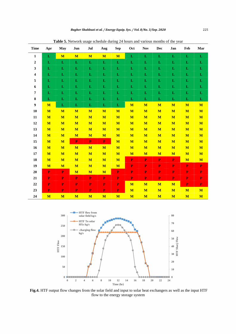
Table 5 presents the time schedule of network consumption during 24 hours and various months of the year. As can be seen, the amount of consumption is divided into three categories: low (L), medium (M), and peak (P). The purchase price of electricity generated by the power grid in these three times is different; for example, at peak times, it is twice the low load times. Figure 4 depicts HTF output flow from the solar field, which is changed by a variable speed pump upon changes in solar DNI intensity, so the output temperature stays constant at 392 degrees and shows the HTF flow to the solar heat exchangers in the cycle to generate steam. Evidently, when DNI levels reach over design point (800 MW/m2), the surplus of HTF flow (relative to design point) is sent to energy storage heat exchangers.
Fig. 3. Temperature variations and solar DNI on the 173th day of the year.
15
20
25
30
35
40
0
100
200
300
400
500
600
700
800
900
1000
0 2 4 6 8 10 12 14 16 18 20 22 24
Am
bie
nt
Tem
pera
ture (
0C
)
DN
I (w
/m2)
Time (hr)
DNI W/m^2 Tamb C
Bagher Shahbazi et al. / Energy Equip. Sys. / Vol. 8/No. 3/Sep. 2020 225
Table 5. Network usage schedule during 24 hours and various months of the year
Time Apr May Jun Jul Aug Sep Oct Nov Dec Jan Feb Mar
1 L M M M M M L L L L L L
2 L L L L L L L L L L L L
3 L L L L L L L L L L L L
4 L L L L L L L L L L L L
5 L L L L L L L L L L L L
6 L L L L L L L L L L L L
7 L L L L L L L L L L L L
8 L L L L L L L L L L L L
9 M L L L L L M M M M M M
10 M M M M M M M M M M M M
11 M M M M M M M M M M M M
12 M M M M M M M M M M M M
13 M M M M M M M M M M M M
14 M M M M M M M M M M M M
15 M M P P P M M M M M M M
16 M M M M M M M M M M M M
17 M M M M M M M M M M M M
18 M M M M M M P P P P M M
19 M M M M M M P P P P P P
20 P P M M M P P P P P P P
21 P P P P P P P P P P P P
22 P P P P P P M M M M P P
23 P P P P P P M M M M M M
24 M M M M M M M M M M M M
Fig.4. HTF output flow changes from the solar field and input to solar heat exchangers as well as the input HTF
flow to the energy storage system
0
10
20
30
40
50
60
70
80
0
50
100
150
200
250
300
0 2 4 6 8 10 12 14 16 18 20 22 24
HT
F S
harj
Flo
w
HT
F F
low
Time (hr)
HTF flow from
solar field kg/s
HTF To solar
HXs kg/s
charging flow
kg/s

226 Bagher Shahbazi et al. / Energy Equip. Sys. / Vol. 8/No. 3/Sep. 2020
Figure 5 shows the storage tank level, which is filled on the determined day.
Figure 6 shows the output HTF flow from the solar section, HTF flow sent to the solar heat exchangers in the combined cycle
throughout the day as well as for the two discharge scenarios. Table 6 presents the geometric information for the tanks designed using the hypotheses.
Fig.5. Changes in tank storage levels during the day
Fig.6. Flow rate changes of the HTF sent to the solar heat exchangers during charge and discharge
Table 6. Geometric parameters related to storage tanks
Stored Fluid Nitrate Salt 60% NaNO3 - 40% KNO3 by wt
Volume 1419 m3
hours of storage 6.2 hr
Nominal capacity 92.8 MWhr
tank side flow rate operation/rated 112 / 117 kg/s
Field side flow rate 67 kg/s
Hot tank Temperature 387 oC
Cold tank Temperature 302 oC
Field-side pump auxiliary power 221.3 kW
Tank-side pump auxiliary power 35.9 kW

Bagher Shahbazi et al. / Energy Equip. Sys. / Vol. 8/No. 3/Sep. 2020 227
3.2. The economic model In industry, the economic performance of power plants used to be measured by the LCOE as one of the most important performance indicators. The LCOE is a measure of cost per unit-energy produced over the course of the lifetime of a power plant. In different scales of operation and level of investments, for comparing different energy technologies, the LCOE was used. Equation 11 illustrates that the LCOE is presented as the ratio between the lifetime cash outflows of the project and the lifetime electricity yield. Key inputs to calculating LCOE include capital costs, fuel costs, fixed and variable operations, and maintenance (O&M) costs, financing costs, capacity factor, availability factor, discount rate, plant life and an assumed utilization rate, which is denoted in US cents/kWh [26-32]. Hence,
1
1
( ( & ) )n
t t t t
t
n
t
t
I O M F C
LCOE
E
and
(11)
(1 )
(1 ) 1
n
t Total n
i iI I
i
.
Capacity factor
The ratio between the actual output power of the power plant and its maximum potential output power over a specific period is defined as the capacity factor.
Availability factor
In the situation that a power plant operates continuously at full output, the amount of its power can deliver as a ratio of what it would provide is presented as the availability factor. The availability factor is including time for forced outages caused by plant trips or failures and for scheduled outages to complete any maintenance or significant overhauls.
Capital cost
For an ISCC, the capital costs are those costs considered in the EPC price, and those include the main equipment (GT's, HRSG's,
ST's, condensers, solar section and cooling system), construction and commissioning costs, transport, contractor's fee, and contingency. The main OEM types of equipment (i.e., the GT, ST, solar section and the generators) are the most expensive components of an EPC price.
Discount rate
The time value of money is considered as the discount rate, which is typically related to the rate of return that could be earned on comparable investments. A discount rate is the best solution for calculating future costs and power generation outputs translation, which presents values and calculates the costs per unit of produced energy. Typical discount rates for LCOE calculations are between 5% and 10%, and the rates can affect LCOE calculations significantly. A 6% discount rate is assumed for the base case of this study.
Fuel cost
Because fuel cost can make up to 80% of the total costs, it is one of the most important factors in an LCOE for a CCGT. In comparison with renewable energy, the low capital costs compensate for the high fuel costs in an LCOE calculation. In this study, the fuel source is only natural gas. The fuel gas cost is represented in US$ per SI Thermal Units (MWh). The initial case of this study assumes 26 $/MWh for fuel cost.
O&M costs (fix and variable)
Fixed O&M costs, is represented in US $/kW/year typically include spare parts, planned maintenance activities, and any owner's costs such as wages, leases, insurance, etc. Fixed costs for ISCC are not as high as other thermal generation technologies that require a low level of staff, and changes in electricity generation levels do not lead to significant changes in costs. The inflation rate (O&M escalation rate) for both the fixed and the variable costs is 2.38% per annum.
Plantlife
228 Bagher Shahbazi et al. / Energy Equip. Sys. / Vol. 8/No. 3/Sep. 2020
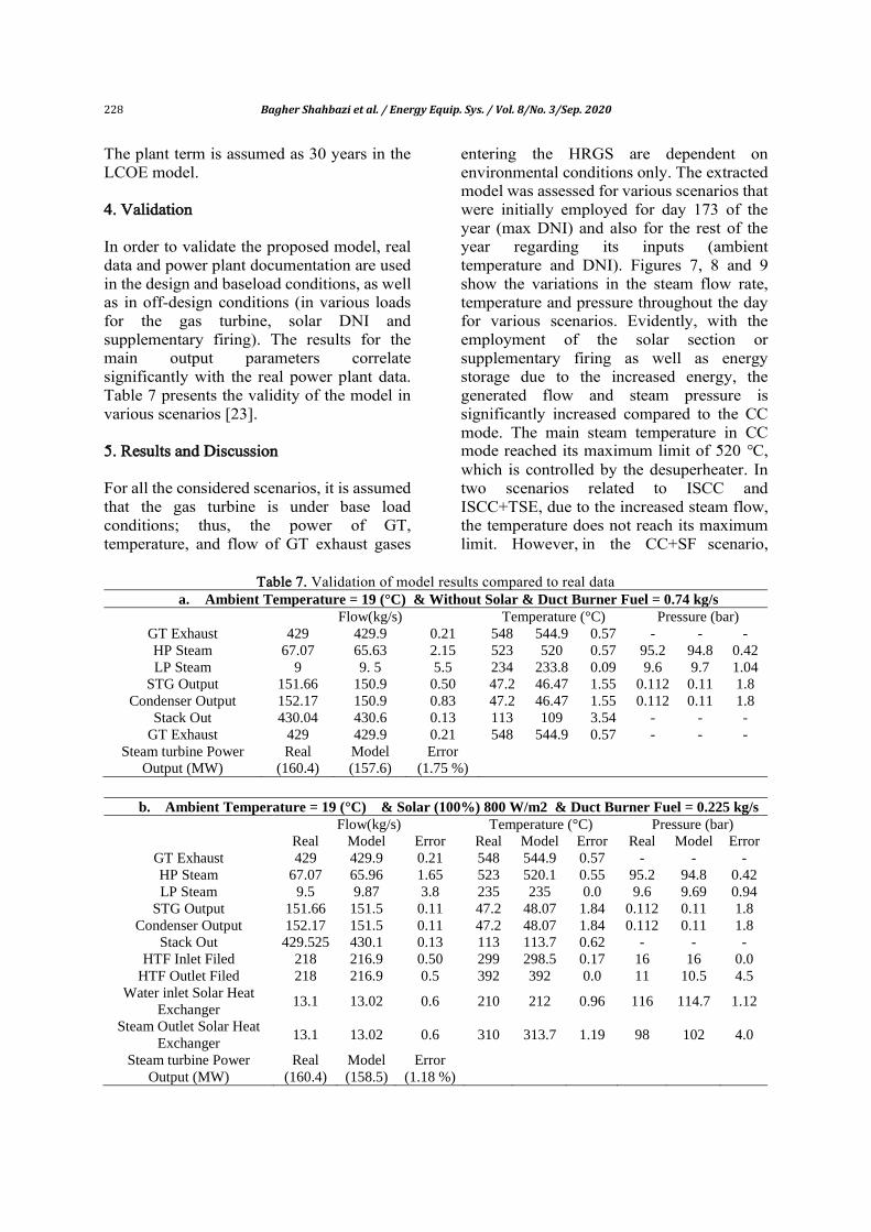
The plant term is assumed as 30 years in the LCOE model.
4. Validation In order to validate the proposed model, real data and power plant documentation are used in the design and baseload conditions, as well as in off-design conditions (in various loads for the gas turbine, solar DNI and supplementary firing). The results for the main output parameters correlate significantly with the real power plant data. Table 7 presents the validity of the model in various scenarios [23]. 5. Results and Discussion For all the considered scenarios, it is assumed that the gas turbine is under base load conditions; thus, the power of GT, temperature, and flow of GT exhaust gases
entering the HRGS are dependent on environmental conditions only. The extracted model was assessed for various scenarios that were initially employed for day 173 of the year (max DNI) and also for the rest of the year regarding its inputs (ambient temperature and DNI). Figures 7, 8 and 9 show the variations in the steam flow rate, temperature and pressure throughout the day for various scenarios. Evidently, with the employment of the solar section or supplementary firing as well as energy storage due to the increased energy, the generated flow and steam pressure is significantly increased compared to the CC mode. The main steam temperature in CC mode reached its maximum limit of 520 ℃, which is controlled by the desuperheater. In two scenarios related to ISCC and ISCC+TSE, due to the increased steam flow, the temperature does not reach its maximum limit. However, in the CC+SF scenario,
Table 7. Validation of model results compared to real data
a. Ambient Temperature = 19 (°C) & Without Solar & Duct Burner Fuel = 0.74 kg/s
Flow(kg/s) Temperature (°C) Pressure (bar)
GT Exhaust 429 429.9 0.21 548 544.9 0.57 - - -
HP Steam 67.07 65.63 2.15 523 520 0.57 95.2 94.8 0.42
LP Steam 9 9. 5 5.5 234 233.8 0.09 9.6 9.7 1.04
STG Output 151.66 150.9 0.50 47.2 46.47 1.55 0.112 0.11 1.8
Condenser Output 152.17 150.9 0.83 47.2 46.47 1.55 0.112 0.11 1.8
Stack Out 430.04 430.6 0.13 113 109 3.54 - - -
GT Exhaust 429 429.9 0.21 548 544.9 0.57 - - -
Steam turbine Power
Output (MW)
Real
(160.4)
Model
(157.6)
Error
(1.75 %)
b. Ambient Temperature = 19 (°C) & Solar (100%) 800 W/m2 & Duct Burner Fuel = 0.225 kg/s
Flow(kg/s) Temperature (°C) Pressure (bar)
Real Model Error Real Model Error Real Model Error
GT Exhaust 429 429.9 0.21 548 544.9 0.57 - - -
HP Steam 67.07 65.96 1.65 523 520.1 0.55 95.2 94.8 0.42
LP Steam 9.5 9.87 3.8 235 235 0.0 9.6 9.69 0.94
STG Output 151.66 151.5 0.11 47.2 48.07 1.84 0.112 0.11 1.8
Condenser Output 152.17 151.5 0.11 47.2 48.07 1.84 0.112 0.11 1.8
Stack Out 429.525 430.1 0.13 113 113.7 0.62 - - -
HTF Inlet Filed 218 216.9 0.50 299 298.5 0.17 16 16 0.0
HTF Outlet Filed 218 216.9 0.5 392 392 0.0 11 10.5 4.5
Water inlet Solar Heat
Exchanger 13.1 13.02 0.6 210 212 0.96 116 114.7 1.12
Steam Outlet Solar Heat
Exchanger 13.1 13.02 0.6 310 313.7 1.19 98 102 4.0
Steam turbine Power
Output (MW)
Real
(160.4)
Model
(158.5)
Error
(1.18 %)

Bagher Shahbazi et al. / Energy Equip. Sys. / Vol. 8/No. 3/Sep. 2020 229
Fig.7. Changes in generated steam flow for various scenarios during the day
Fig.8. Changes in generated steam temperature for various scenarios during the day
Fig.9. Changes in generated steam pressure for various scenarios during the day
50
52
54
56
58
60
62
64
66
0 2 4 6 8 10 12 14 16 18 20 22 24
HP
S f
low
(k
g/s
)
Time (hr)
ISCC+TES
ISCC
CC+SF
CC
510
512
514
516
518
520
522
0 2 4 6 8 10 12 14 16 18 20 22 24
HP
S T
em
pera
ture (
0c)
Time (hr)
ISCC+TES ISCC CC+SF CC
76
78
80
82
84
86
88
90
92
94
0 2 4 6 8 10 12 14 16 18 20 22 24
HP
S P
ress
ure (
bar)
Time (hr)
ISCC+TES ISCC CC+SF CC

230 Bagher Shahbazi et al. / Energy Equip. Sys. / Vol. 8/No. 3/Sep. 2020
similar to scenario CC, the temperature reaches its maximum limit. With increased input gas temperature to the HRSG with fuel consumption in the burners, water spraying in the desuperheater increases to limit the temperature of the main steam to 520 ℃, and subsequently, the generated steam flow will also increase. Figure 10 shows the variations in power production during this day for various scenarios.
5.1. Annual energy sector results
The results of the annual system performance for various defined scenarios are presented in terms of environmental conditions as inputs (ambient temperature and DNI) in Figs.11-14. Evidently, the Fig.11 shows the generated power by the power plant in various months of the year for various scenarios. As can be
seen in this figure, the amount of power generated at different months of the year for both the ISCC scenario and the CC + SF scenario is significantly higher than the CC scenario. And in the ISCC + TES scenario, the power generation capacity increased compared to the ISCC scenario due to the storage of solar energy at peak radiation times and the use of this energy in the cycle at peak hours of consumption. And, as can be seen, the power outputs for the two ISCC and CC + SF scenarios are the same, considering the assumption made by the authors to compare these two scenarios. Figure 12 shows the share of solar power generated by the solar section. The amount of energy sent to the energy storage system for storing and discharging energy from the system in different months of the year is shown in Fig.13.
Fig. 10. Changes in generated power for various scenarios during the day
Fig.11. Production power for various scenarios in annual performance
310
320
330
340
350
360
370
380
0 2 4 6 8 10 12 14 16 18 20 22 24
Net
Pow
er (
MW
)
Time (hr)
ISCC+TES
ISCC
CC+SF
CC
230
240
250
260
270
280
290
300
Jan Feb Mar Apr May Jun Jul Aug Sep Oct Nov Dec
Increm
en
tal
en
ergy f
rom
sola
r (G
Wh
)
Month
CC ISCC or CC+SF ISCC+TES

Bagher Shahbazi et al. / Energy Equip. Sys. / Vol. 8/No. 3/Sep. 2020 231
Fig.12. The share of generated power by the solar section in ISCC in the annual performance
Fig.13. The amount of energy stored and discharged monthly from the energy storage system
Figure 14 shows the amount of fuel
consumption and CO2 produced by supplementary firing. The use of solar energy increases the annual plant power production by 40 GWh, which equals 2.2% of the total production capacity. In order to produce this quantity of power using the supplementary firing, fuel consumption should be approximately 1.98 tons, which increases the production of CO2 by the power plant by 18 kton. Due to the increased input, the gas temperature to the HRSG, the lifespan of the superheater heat exchangers exposed to this temperature will be reduced. In the fourth scenario, the use of an energy storage system increases power production by 5 GWh in peak times with a higher sales price.
5.2. Annual results of the economic
section
The annual economic analysis of the system is presented for four scenarios based on the value of LCOE with sensitivity analysis on input economic parameters that are presented in Table 8. The input economic parameters with implemented sensitivity analysis include different fuel prices, deviations in the investment cost estimate for the solar field, discount rate, and CO2 gas emission costs. The values of these parameters are at a base value of 26 $/MWh for fuel price, CO2 gas emission cost is 25 $/tonCO2, the solar field cost is 350 $/m2, and the discount rate is
2
3
4
5
6
7
8
Jan Feb Mar Apr May Jun Jul Aug Sep Oct Nov Dec
Increm
en
tal
en
ergy f
rom
sola
r (G
Wh
)
Month
0
0.1
0.2
0.3
0.4
0.5
0.6
0.7
0.8
0.9
1
Jan Feb Mar Apr May Jun Jul Aug Sep Oct Nov Dec
Sto
rage
Ener
gy (
GW
h)
Month
Storage sharj Energy
storage desharj Energy

232 Bagher Shahbazi et al. / Energy Equip. Sys. / Vol. 8/No. 3/Sep. 2020
considered 6%. The obtained results for the annual performance based on the aforementioned conditions for various scenarios show that the value of LCOE for (CC) is equal to 8.99 cents/kWh, 8.99 cents/kWh for (CC+SF), 9.04 cents/kWh for (ISCC) and 9.13 cents/kWh for (ISCC+TES). Sensitivity analysis on the economic parameter values was conducted by considering changes in input parameters in four cases (low, base cases, high, very high): discount rate (4, 6, 8, 10%), contingency in the investment cost estimate for the solar part (-10, 0, 5, 20%), fuel prices (20, 26, 33, 40
$/MWh) and CO2 emission costs (0, 25, 50,75 $/tonCO2). The results of the sensitivity analysis show that when increasing discount rate, the LCOE rate will increase in all scenarios and such increase is higher in terms of significant investment costs for the solar section and energy storage system for these two scenarios (ISCC, ISCC+TSE) compared to the scenarios pertaining to CC and (CC+SF). Increased contingency considered for the solar part and added to the combined cycle in a state where contingency is -10%, entails lower LCOE for the ISCC scenario compared to the CC and (CC+SF) scenarios.
Fig. 14. Increase in fuel consumption and CO2 produced in various scenarios of using the supplementary firing
Table 8. LCOE results for various scenarios with sensitivity analysis on main input parameters
Cassese LCOE (CC) LCOE (Burner) LCOE (ISCC) LCOE (Storage)
Discount Rate Base 6% 8.9888 8.8623 9.0109 9.1357
4% 8.8646 8.7401 8.8712 8.977
8% 9.1203 8.9916 9.1588 9.2822
10% 9.2582 9.1272 9.314 9.4468
Contingency Base 0% 8.9888 8.8623 9.0109 9.1357
5% 8.9888 8.8623 9.0983 9.2653
20% 8.9888 8.8623 9.3605 9.5278
-10% 8.9888 8.8623 8.8361 9.0028
Fuel Cost Base 8 8.9888 8.8623 9.0109 9.1357
6 EUR 7.3728 7.2778 7.4324 7.5557
10 EUR 10.6048 10.4468 10.5894 10.7158
12 EUR 12.2208 12.0312 12.1678 12.2959
CO2 Base 25 8.9888 8.8623 9.0109 9.1357
0 $/kton 8.0173 7.8659 8.062 8.1858
50 $/kton 9.9603 9.8587 9.9598 10.0857
0
500
1000
1500
2000
2500
3000
3500
4000
0
50
100
150
200
250
300
350
400
Jan Feb Mar Apr May Jun Jul Aug Sep Oct Nov Dec
CO
2 (
ton)
Fuel
Co
nsu
mp
tio
n (
kg)
Month
Duct Burner Fuel (kg) Duct Burner CO2 Generation (kg)

Bagher Shahbazi et al. / Energy Equip. Sys. / Vol. 8/No. 3/Sep. 2020 233
The next examined case was sensitivity analysis on fuel costs, where results show that when fuel prices are reduced compared to the base value, the difference between LCOE in the ISCC scenario is increased compared to the CC and (CC+SF) scenario which reduces the economic feasibility of the ISCC. However, with increased fuel prices, the LCOE value in the CC and (CC+SF) scenarios are increased compared to the ISCC, and the overall LCOE value for the ISCC is less compared to the CC and (CF+SF) scenarios. 6. Conclusion In recent years, regarding issues such as the exhaustion of fossil fuels and global warming, the improvement of thermal plan efficiency and the use of new energy sources is inevitable. Among the options for utilizing new energy sources, the use of solar energy has gained considerable attention. An ISCC plant is the most prominent and practical solar energy scheme. In this paper, the off-design point model of a combined cycle using mathematical equations, including mass preservation equations, momentum, and energy, heat transfer, etc. have been developed and used to analyze its performance in various scenarios. Key findings of this research can be summarized as follows: Results show that the production power,
efficiency, and the heat rate for the reference combined cycle are 45 / 384 MW, 50/75%, and 7093/55 MJth/MWel at design point (ambient temperature, 19 o
C), respectively and these values in the condition of using solar energy are 403/45, 53/51% and 6727/4 MJth/MWel, respectively. Under the condition of using supplementary firing instead of solar energy to generate the same power as the ISCC scenario, these values will be 403/45, 50/54%, 7093/55 MJth/MWel, respectively.
The annual power generation capacity of the solar section is approximately 40 GWh, which is 2.2% of the total power generated by the power plant.
The annual reduction of CO2 emission due to the use of solar energy will be about 18 kton, and the use of solar energy will entail reduced fuel consumption by 1.98 kton. It is noteworthy that the use of solar energy instead of supplementary firing will eliminate limitations in terms of temperature pertaining to the input steam temperature entering the steam turbine and the metal temperature of heat exchanger metal in HRSG (superheaters) when using supplementary firing during the warmer hours of the year.
By using the energy storage system, annual power generation increases by 5 GWh, which, if this increase occurs in peak hours (scenario 2 discharging), will increase the plant's annual revenue by 20 M$, which is 5 M$ more than the scenario 1 discharging.
By using the energy storage system, the annual power generation increases by 5 GWh, which will raise the plant's annual revenue by 0.25 M$ if the increment occurs in peak hours (scenario 2 discharging).
An economic analysis conducted for various scenarios shows that the LCOE value for these scenarios are (8.86, 8.99, 9.04, 9.14 cents/kWh) and sensitivity analysis on economic parameters show that by increasing fuel prices by 40 $/MWh or increasing CO2 gas emission price by 50 $/kton, LCOE costs related to the ISCC scenario will be less compared to the CC scenario.
References
[1] Liu Z, Karimi I. Simulation and
optimization of a combined cycle gas turbine power plant for part-load operation. Chemical Engineering Research and Design. 2018; 131:29-40
[2] Ersayin E, Ozgener L. Performance analysis of combined cycle power plants: a case study. Renew Sustain Energy. Rev 2015; 43:832–842.
[3] Cavalcanti EJC. Exergoeconomic and exergoenvironmental analyses of an integrated solar combined cycle system.

234 Bagher Shahbazi et al. / Energy Equip. Sys. / Vol. 8/No. 3/Sep. 2020
Renew Sustain Energy. Rev 2017; 67:507–519.
[4] Zhu G, Neises T, Turchi C, Bedilion R. Thermodynamic evaluation of solar integration into a natural gas combined cycle power plant. Renewable Energy. 2015; 74:815–824.
[5] Rovira A, Montes MJ, Varela F, Gil M. Comparison of heat transfer fluid and direct steam generation technologies for integrated solar combined cycles. Appl Therm Eng. 2013; 52:264–274.
[6] Montes MJ, Rovira A, Muñoz M, Martínez M. Performance analysis of an Integrated Solar Combined Cycle using Direct Steam Generation in parabolic trough collectors. Appl Energy. 2011; 88:3228–3238.
[7] Pramanik S, Ravikrishna RV. A review of concentrated solar power hybrid technologies. Applied Thermal Engineering. 2017; 127:602-637.
[8] Aldali Y, Morad K. Numerical simulation of the integrated solar/north Benghazi combined power plant. Applied Thermal Engineering. 2016;108: 785 – 792.
[9] J. Li, X. Yu, J. Wang, S. Huang, coupling performance analysis of a solar aided coal-fired power plant. Applied Thermal Engineering. 2016;106: 613 – 624.
[10] Wang Y, Xu J, Chen Z, Cao H, Zhang B. Technical and economical optimization for a typical solar hybrid coal-fired power plant in china. Applied Thermal Engineering 2017;115: 549 – 557.
[11] Mabrouk MT, Kheiri A, Feidt M. A Systematic procedure to optimize Integrated Solar Combined Cycle power plants (ISCCs). Applied Thermal Engineering. 2018;136: 97-107.
[12] Behar O, Khellaf A, Mohammedi K, Ait-Kaci S. A review of integrated solar combined cycle system (ISCCS) with a parabolic trough technology. Renew Sust Energy Rev. 2014; 39:223–250.
[13] Jamel MS, Rahman AA, Shamsuddin AH, Advances in the integration of solar thermal energy with conventional and non-conventional power plants. Renew Sust Energy Rev. 2013; 20:71–81.
[14] Manente G, High performance integrated solar combined cycles with
minimum modifications to the combined cycle power plant design. Energy Conversion and Management. 2016; 111:186–197.
[15] Turchi CS, Ma Z, Erbes M. Gas Turbine/Solar Parabolic Trough Hybrid Designs, in: Proc. ASME Turbo Expo, ASME, 201: 989–996.
[16] Kelly B, Herrmann U, Hale M. Optimization studies for integrated solar combined cycle systems. in: Proceedings of the ASME international solar energy conference, Washington DC, USA; 2001:393- 398
[17] Li Y, Yang Y. Thermodynamic analysis of a novel integrated solar combined cycle. Applied Energy. 2014; 122:133–142
[18] Dersch J, Geyer M, Herrmann U, JonesSA, Kelly B, Kistner R, Ortmanns W, Pitz-Paal R, Price H, Trough integration into power plants- a study on the performance and economy of integrated solar combined cycle systems. Energy. 2004;29: 947-959
[19] Allani Y, Favrat D, von Spakovsky M. CO2 mitigation through the use of hybrid solar-combined cycles. Energy Conversion and Management. 1997;38: 661-667.
[20] Cau G, Cocco D, Tola V. Performance and cost assessment of Integrated Solar Combined Cycle Systems (ISCCSs) using CO2 as heat transfer fluid, Sol Energy. 2012;86: 2975–2985.
[21] Nezammahalleh H, Farhadi F, Tanhaemami M. Conceptual design and techno-economic assessment of integrated solar combined cycle system with DSG technology. Sol Energy. 2010;84: 1696–1705.
[22] Hermann Ulf, Kearney D. Survey of Thermal Energy Storage for Parabolic Trough Power Plants. Journal of Solar Energy Engineering. 2002; 124:145-152.
[23] Shahbazi B, Talati F, Mahmoudi S.M.S., Yari Mortaza, Developing Off-Design Model of Yazd integrated solar combined cycle for analyzing environmental benefits of using solar energy instead of supplementary firing. Energy Equipment and system. 2018;6: 429–448.

Bagher Shahbazi et al. / Energy Equip. Sys. / Vol. 8/No. 3/Sep. 2020 235
[24] Joseph K, Boehm RF. Comparison of Two-Tank Indirect Thermal Storage Designs for Solar Parabolic Trough Power Plants. ASME 2009 3rd International Conference on Energy Sustainability. 2009; 2:683-688.
[25] Robert W, Serth. Process Heat Transfer Principles, Applications and Rules of Thumb, Department of Chemical and Natural Gas Engineering, Texas A&M University-Kingsville, Kingsville, Texas, USA, 2014 Elsevier Inc.
[26] US Energy Information Administration (EIA), Levelized Cost and Levelized Avoided Cost of New Generation Resources in the Annual Energy Outlook, June 2015.
[27] World Energy Perspective, Cost of Energy Technologies, ISBN: 978 0 94612 130 4, 2013.
[28] International Energy Agency (IEA), Projected Costs of Generating Electricity, 2010.
[29] Technology Data for Energy Plants, Generation of Electricity and District Heating, Energy Storage and Energy
Carrier Generation and Conversion, Energy Styrelsen, 2012.
[30] Mehrpooya M, Tosang E, Dadak A. Investigation of a combined cycle power plant coupled with a parabolic trough solar field and high-temperature energy storage system, Energy Convers Manag (2018) 171:1662-1674.
[31] Jayanta Deb M, Cillian C. Techno-economic assessments of advanced Combined Cycle Gas Turbine(CCGT) technology for the new electricity market in the United Arab Emirates, Sustainable Energy Technologies and Assessments (2017) 19:160-172.
[32] Khademi M, Behzadi Forough A, Khosravi A, economic operation optimization of an HRSG in combined cycle power plants based on evolutionary algorithms: A case study of Yazd, Iran. Energy Equipment and system. 2019;7: 67–79.