Energy efficient multistage zeolite drying for heat sensitive - E-depot
170
Energy Efficient Multistage Zeolite Drying for Heat Sensitive Products Mohamad Djaeni
Transcript of Energy efficient multistage zeolite drying for heat sensitive - E-depot

Energy Efficient Multistage Zeolite Drying
for Heat Sensitive Products
Mohamad Djaeni
ii
Promotoren:
Prof. dr. ir. G. van Straten Hoogleraar in de Meet-, Regel- en Systeemtechniek Wageningen Universiteit Prof. dr. J.P.M. Sanders Hoogleraar Valorisatie van plantaardige productieketens Wageningen Universiteit Copromotoren:
Dr. ir. A.J.B. van Boxtel Universitair docent, leerstoelgroep Meet-, Regel- en Systeemtechniek Wageningen Universiteit Dr. ir. P.V. Bartels Senior onderzoeker, AFSG Fresh Food and Chains Wageningen Universiteit and Research Centrum
Promotie-commissie:
Prof. dr. ir. R.M. Boom
Wageningen Universiteit
Prof. dr.-Ing. Habil. Evangelos Tsotsas
Otto-von-Guericke University of Magdeburg, Germany
Prof. dr. ir. P.M.M. Bongers
Technische Universiteit Eindhoven
Dr. ir. P.J.T. Bussmann
TNO Kwaliteit van Leven, Zeist
Dit onderzoek is uitgevoerd binnen de onderzoekschool VLAG

iii
Energy Efficient Multistage Zeolite Drying
for Heat Sensitive Products
Mohamad Djaeni
Proefschrift
ter verkrijging van de graad van doctor
op gezag van de rector magnificus
van Wageningen Universiteit,
Prof. dr. M.J. Kropff
in het openbaar te verdedigen
op vrijdag 21 november 2008
des namiddags te half twee in de Aula

iv
Energy Efficient Multistage Zeolite Drying for Heat Sensitive Products
Mohamad Djaeni PhD thesis, Wageningen University, The Netherlands, 2008
With summaries in English, Dutch and Bahasa Indonesia
ISBN:978-90-8585-209-4

v
Preface
This thesis presents the research for my PhD-thesis in the Systems and Control Group
and Valorisation of Plant Production Chains Group, department of Agrotechnology and Food
Science and A&F of Wageningen University and Research Centre. The research was funded by
TPSDP Project Diponegoro University Semarang Indonesia, and the Energy Research Program
EOS of the Dutch Ministry of Economics conducted by SenterNovem (project NEOT01005). The
topic concerns energy efficient adsorption drying using zeolite for heat sensitive products and
was supervised by dr. Ir. A.J.B. van Boxtel, dr. ir. P.V. Bartels, Prof. dr. J.P.M. Sanders and Prof.
dr. ir. G. van Straten. To facilitate the research an adsorption dryer was constructed by Ebbens
Engineering, zeolite was provided by CECA (Brenttag), C.J. van Asselt and B. Speetjens assisted
with the measurement and control system.
The research involves the evaluation of the energy consumption of a conventional dryer,
the development of single and multistage adsorber drying systems using zeolite for air
dehumidification, the characterization of transport phenomena in zeolite beds and material to be
dried by using one and two dimensional models, the evaluation of the energy efficiency for the
developed dryer systems, the construction of an experimental dryer and evaluation of the energy
performance of this system, the prediction of the dryer performance for a range of operational
conditions, and suggestions for the construction of the drying concept for large scale application.
The work is given in seven chapters where five chapters are published in or submitted to an
international journal. Moreover, other part of the works have been presented at national and
international seminars.

vi

vii
Contents
Chapter 1: Reducing Energy Consumption In Drying:
A Challenge For Adsorption Drying 1
Chapter 2: Process Integration for Food Drying with Air Dehumidified by Zeolites 13
Chapter 3: Multistage Zeolite Drying For Energy Efficient Drying 41
Chapter 4: Energy Efficiency of Multistage Adsorption Drying for
Low Temperature Drying 69
Chapter 5: Computational Fluid Dynamics for Multistage Adsorption Dryer Design 83
Chapter 6: Performance Evaluation of Adsorption Dryer Using Zeolite 113
Chapter 7: Adsorption Dryer: Evaluation and Future Development 137
Summary 151
Samenvatting 153
Ringkasan 155
Acknowledgement 157
Curriculum Vitae 159
List of Publications 160
Training Activities 161


Chapter 1
Reducing Energy Consumption in Drying:
a Challenge for Adsorption Drying

Chapter 1
2
1. Energy consumption in drying
Drying is a basic operation in food, pharmaceutical and chemical industry. The operation
is important to enhance the preservation properties of agriculture crops and pharmaceutical
products, to reduce the costs for transportation, and to increase costumer convenience of food
products. An example is milk powder that can be stored for a period longer than a year instead of
some weeks[1] and for which the transportation volume is 8-10 times reduced. Nowadays, the
importance of powdered food products as for example soups, sauces and dried yeasts is
increasing for consumer convenience.
A large part of the total energy usage in industry is spent in drying. For example 70% of
total energy spent in the production of wood products, 50% of textile fabrics, 27% of paper, 33%
of pulp production is used for drying[2] (see Figure 1.1). In food and pharmaceutical industry the
energy consumption for drying is around 15% of the total energy usage in this sector. Energy
spent for drying varies between countries and ranges between 15-20% of the total energy
consumption in industry.[3]
0%
20%
40%
60%
80%
Wood Textile and clothing Pulp and paper Food and bevarage
Type of industries
Percentage of total energy for drying Wood
Textile and clothing
Pulp and paper
Food and bevarage
Figure 1.1: Percentage of energy used for drying for several industries
Currently several drying methods are used, ranging from traditional to modern
processing: e.g. direct sun drying, convective drying, microwave and infra-red drying, freeze and
vacuum drying. Current drying technology is often not efficient in terms of energy consumption
and has a high environmental impact due to combustion of fossil fuel or wood as energy source.[4]
The sources of fossil fuel are limited, the price of energy increases, the world wide industrial
energy usage rises, and increase of greenhouse gas emission becomes a global issue due to
climate change; the need for a sustainable industrial development with low capital and running
cost especially for energy becomes more and more important. In this context the development of

Reducing Energy Consumption in Drying :A Challenge for Adsorption Dryer
3
efficient drying methods with low energy consumption is an important issue for research in drying
technology.
A large range of drying methods is being applied by small and industrial users. Next
consideration is just a limited review on some major drying methods. Direct sun drying is simple
and doesn’t need fuel fossil for energy generation, but the system needs a large drying area, long
drying time (often 3-5 days), high operational cost for labour, and depends highly on the climate.
Furthermore, product contamination may occur due to the open air conditions and therefore sun
dried food products are not accessible for all markets. Improvement of this drier type has been
achieved by using for example a solar tunnel drier equipped with an electric fan to dry chilli.[5]
Although, the result showed that the processing time is reduced, it is still rather long (2-3 days).
Convective drying[6] is more attractive than sun drying because of the shorter operational
time, low product contamination, lower operational costs, no dependency on the climate, and
relative limited space usage. However, the disadvantage of this system is that the product quality
can be affected by the operational temperature, and the high energy consumption.
Vacuum and freeze drying systems are operated in the temperature range –20 to –0oC
and for pressures in the range of 0.0006 to 0.006 atm.[7,8] These systems are useful for the
production of high quality, high value products with minimizing flavour loss and degradation
reactions (e.g. protein denaturation, browning and enzymatic reactions [9]). However, Hu et al[7]
showed the vacuum freeze- dryer is high energy consumption, investment costs, and long drying
time.
Considerable amounts of energy are lost in the off-gas of convective drying systems. The
off-gas temperatures are commonly in the range 60-90°C but may even rise till 120°C as
reported for spray drying of Roselle extracts[10] and sugar-rich food products. Until now, off-gas
flows with these temperatures are hardly recovered for use in other processes. As a result, the
energy efficiency of drying is poor. The energy equivalent of about 1.5 kg of steam to remove 1
kg of water (i.e. 65% energy efficiency) is common for spray drying, and for low temperature
drying of heat sensitive products (food and medicines) the required amount of energy exceeds 2
kg steam for 1 kg water removal (i.e. below 50% energy efficiency).
The energy efficiency depends on various process characteristics such as evaporation
rate, steam consumption, and energy uptake by other processing units. A common definition for
energy efficiency is the ratio between the total energy required for evaporating water from the
product and the total amount of energy introduced to the system (see equation 1).[2] Table 1.1
presents the energy efficiency for drying compiled from various sources.
evap
intr,total
Qη= 100%
Q (1)
Considering the given energy efficiency values it is a challenge to work on the
development of innovative dryers with a high drying rate, high energy efficiency, low investment

Chapter 1
4
and operational costs, and feasible for low and medium drying temperatures.[7] Innovation and
research in drying technology during the last decades resulted in reasonable improvements, but
breakthrough solutions with respect to the energy efficiency are scarce. Some authors state that
innovation in drying technology tends to reach a saturation level[4] and a further significant
reduction in energy consumption seems not feasible. Positive results are obtained in zeolite
drying to speed up drying rate and to improve energy efficiency,[14-17] while other new developed
drying processes cannot compete with traditional drying method in terms of energy efficiency and
operational cost[4].
Table 1.1: comparison of average efficiency for drying in selected dryers
No. Dryer Type Energy efficiency
(η %)
Steam consumption
(kg steam/kg water removal)
1 Cabinet dryer[11] 20-30 3.0-5.0
2 Vacuum-shelf dryer[11] 35-40 2.5-3.0
3 Freeze-dryer[11] 10-20 5.0-10.0
4 Spray dyer [12] 30-60 1.6-3.0
6 Screw conveyor dryer[13] 25-60 1.6-4.0
7 Fluidized bed dryer* 30-70 1.5-3.0 * compiled from various sources and depends on product type
2. Adsorption dryer for medium temperature drying
The main problem in drying is how to improve the drying rate in combination with
minimizing energy usage. Straightforward solutions are: reducing humidity of air, increasing air
temperature, decreasing air pressure, or combinations of these three. The choice depends on the
heat sensitivity of the product to be dried. Increasing the air temperature or reducing air pressure
reduces both the relative humidity of air which increases the drying capacity and driving force for
drying. However, increasing air temperature leads to quality degradation of heat sensitive
products, while reducing the pressure yields increased operational costs and inefficient energy
usage.
Figure 1.2: A schematic diagram for drying with air dehumidification by condensation. Ambient air is
cooled to 0°C and vapor in air condenses. The dehumidified cold air is heated–up to the required
dryer temperature and fed to the dryer. In the dryer the dehumidified air dries the product and
leaves the drier.
Exhaust Air
Heater
Inlet Product
Outlet Product
Condenser
Ambient Air
Dried Air 10-40oC
Dried Air
Water
Dryer

Reducing Energy Consumption in Drying :A Challenge for Adsorption Dryer
5
Air dehumidification improves the driving force for drying at the same or lower
temperatures, and allows drying at low and medium temperatures and atmospheric pressure.
These conditions are suitable for heat sensitive materials such as food and pharmaceutical
products.
Figure 1.2 presents a conventional dryer for low temperature drying in which air is
dehumidified air by condensation. In a first step air is cooled and the vapor in air condenses.
Then the dehumidified air is heated to the drying temperature. In this system energy is used for
two functions: 1) cooling and condensation of vapor in air, and 2) for heating dehumidified air to
drying conditions[18].This method is energy inefficient. Sosle et al[19] proposed the use of a heat
pump in this system. Compared to the conventional dryer using hot air, the quality product is
better, but the energy efficiency is lower due to much of energy loss in the condenser. Xu et al[20]
proposed a combination of a vacuum freeze dryer and a convective air dryer in two successive
stages. This system could be a potential option, since the product quality is maintained. The
energy efficiency of 50-60% is only meaningful as an alternative for vacuum freeze dryers.
Air dehumidification by using adsorbents[14-17,21] is an other option to enhance the drying
efficiency (see Figure 1.3). With this method, the air is dehumidified by adsorbing vapor while the
air temperature increases at the same time due to the release of the adsorption heat. As a result,
the dryer inlet air contains more sensible heat for drying which improves the total energy
efficiency. However, straightforward application of adsorption dryers using silica, alumina or
zeolite as adsorbent for food and medicinal products is not attractive. By taking into account the
energy for standard regeneration of adsorbents, energy savings compared to a conventional
dryer are estimated to be around 10-15%. In an alternative approach, the zeolite is regenerated
with superheated steam. The benefit of this system is that the energy in the off-gas of the
regeneration unit is nearly fully recovered and can be used for other operations.[17]
Figure 1.3: A schematic diagram of an adsorption dryer in which air is dehumidified by an adsorbent in a
rotating wheel. Ambient air passes the adsorber zone of a rotating wheel where air is
dehumidified and where the air temperature increases. Then, the dehumidified air enters the
dryer where water removed from the wet product. Meanwhile, in the regenerator zone of the
rotating wheel the saturated adsorbent is dried by using hot air from a heater. In the regenerator
the temperature of air decreases while the vapor content increases.
Adsorber
Inlet Product
Outlet Product
Ambient Air Dried
Air
Hot Air
Dryer
Heater Regenerator
Exhaust Air
Ambient Air
Exhaust Hot Air

Chapter 1
6
3. Heat recovery and multistage drying
The main reason for the low energy efficiency in drying is the heat loss in the off-gas from
the dryer. The off-gas flow has a significant energy content since the air contains a high amount
of vapor from which the latent heat can be recovered by condensation (see Figure 1.4). Kemp[22]
applied pinch analysis formulated by Linnhoff[23] to recover energy in conventional drying systems
in order to minimize energy usage, but concluded that for straightforward conventional dryers the
options to reduce energy are limited. Krokida and Bisharat[24] investigated the potential of heat
exchangers, heat pumps, and combinations of heat exchangers and heat pumps for recovery of
sensible and latent heat. The result indicated that 40% of heat loss in the off-gas can be
recovered. However, after taking the amount of energy to realize this into account the
improvement of energy efficiency is marginal and ends at 60%. Iguaz et al[25] proposed the
enhancement of thermal efficiency by recycling exhaust gas from dyers operated above 200°C,
but the energy efficiency comes not further than 65%. Moreover, the system is only suitable for
high temperature drying with superheated vapor.
Figure 1.4: A schematic diagram of a dryer combined with heat recovery to reuse heat of exhaust air and
hot product from dryer. Ambient air is heated in the heat recovery unit using exhaust air from the
dryer and hot product leaving dryer. Subsequently, hot air is heated-up to dryer temperature, and
then it passes the dryer to remove water from the product. Latent and sensible heat in the
exhaust air are recovered in the heat recovery unit.
Multistage drying can also be an option to improve efficiency.[26,27] In this system, the
exhaust air of a dryer is heated again and re-used for a next drying stage. Figure 1.5 gives in a
psychometric chart a comparison of a single-stage and a multistage dryer.[26,27] Important
advantages of this multistage system is that high air temperatures in inlet air are avoided and the
required air flow is below that for a standard dryer. However, the temperatures in the second,
third and next stages increase gradually due to higher moisture content in air after contacting wet
product.
The multistage dryer system provides important benefits compared to conventional
single-stage dryer systems. The evaluation of Holmberg and Ahtila[27] showed that the investment
and operational cost of the multistage dryer competes with a single-stage dryer over a longer
amortization time. The best improvement of energy efficiency was achieved for operational
temperatures below 100°C with 2-4 drying stages where energy savings around 10% can be
Heater
Inlet Product
Hot Product
Exhaust Air
Heat Recovery
Ambient Air
Exhaust Air
Air Dryer
Hot Air
Dryer

Reducing Energy Consumption in Drying :A Challenge for Adsorption Dryer
7
achieved. However, for operational temperatures above 100°C the improvement is not
significant.[28]
Figure 1.5: Comparison of a single-stage and a multistage conventional dryer.[26,27] The single stage dryer
requires a high temperature and purges exhaust air at a higher temperature which implies more
heat loss. In the multistage dryer, the drying can be carried out gradually, which requires lower
dryer temperatures and results in a lower exhaust air temperature.
4. Research challenges
This research focuses on multistage adsorption dryers using zeolite as vapor adsorbent.
zeolite is selected as adsorbent since it can remove nearly all vapor from air. Hence, the driving
force for drying at low and medium temperature drying is increased which yields a high drying
rate while retaining quality of heat sensitive products. Other experimental work also showed the
suitability of zeolite for adsorption drying.[14-17,29] A heat recovery unit based on a heat exchanger
network and air compressor is used in this research to recover sensible and latent heat from the
off-gas. The challenges for research on drying at low and medium operational temperatures are:
1. How to use the zeolite to enhance the energy efficiency of drying systems
2. How to recover heat flows in dryer-adsorption-regeneration system
3. What is the potential for a multistage zeolite drying system?
4. How to design the zeolite drying process operation with proper dimension equipment?
5. Can the zeolite drying system be validated
6. How to use the obtained knowledge to design an energy effective dryer?
Figure 1.6 presents a possible construction of a multistage zeolite dryer. The main benefit
is that the energy content of the exhaust air is reused several times. Moreover, the released
adsorption heat is utilized to heat the air for drying in the succeeding stages. As a consequence,
product drying hardly requires heat supply. The regeneration of spent zeolite from the adsorbers
requires heat supply, but with pinch based heat recovery the net energy input can be kept low.
Humidity in air (kg vapor per kg dry air)
1
4
6
Temperature, °C
Single -stage (0-1’-2’)
0 1’
2’
heating
drying
3 2
Multistage 0-1-2-3-5-6 5

Chapter 1
8
Compared to conventional multistage dryers the concept has more benefits since the vapor
content of the air for the succeeding stages is lower (see Figure 1.7). Hence, the operational
temperature for drying can be also kept low in order to retain product quality and improve driving
force for drying.
.
Figure 1.6: A suggested lay-out for counter-current multistage zeolite dryer. Ambient air is heated up in a
heater and after dehumidification the air is used for product drying. Exiting the dryer, the vapor in
air is removed in a second adsorber and used for drying again. This process is repeated several
times depending on the number of stages. The spent zeolite from the last adsorber stage is re-
activated in the regenerator using hot air obtained by heating-up ambient air in a heat recovery
unit and a heater.
Figure 1.7: Psychometric chart of air. A. Comparison of a single-stage and a multistage zeolite dryer.
Fresh air is fed to the system at position 0. After adsorption and/or heating position 1 is reached
for the multistage systems and 1’ for the single-stage systems. From this point the multistage
systems continue with drying, adsorption or heating along the path 1-2-3 etc until 6. The single-
stage system continues to 2’.
Drying system
Product flow
AmbientAir
Heater
Heater
Regenerator
Product flow
Zeolite beds
Heater
Zeolite beds
Heater
Regenerator
Heat Recovery
Exhaust Air
Zeolite
Exhaust Air
AmbientAir
Temperature, °C
Humidity (kg vapor per kg dry air)
Multistage 0-1-2-3-5-6
2
4
6
Single -stage (0-1’-2’)
0
2’
1’ 1
3
5
adsorption
heating
drying

Reducing Energy Consumption in Drying :A Challenge for Adsorption Dryer
9
5. Research activities
The research aims the development of a multistage drying system using zeolite as
adsorbent. The work will is based on five main steps:
1. Evaluation of energy efficiency in a conventional drying system and process integration for
an adsorption drying system using zeolite,
2. Development of multistage drying system to improve drying efficiency,
3. Evaluation of energy efficiency multistage zeolite drying system for low dryer temperature,
4. Characterization of spatial distribution of temperature and moisture in a multistage zeolite
drying by computational fluid dynamics for designing dryer equipment,
5. Experimental validation to prove parts of the concept.
6. Thesis Outline
Chapter 2 concerns the comparison between conventional dryers and a single-stage
dryer using air dehumidified by zeolite. Steady-state mass and energy balances have been used
and the work concerns drying temperatures ranging from 50-70 °C. Process integration based on
pinch analysis has been applied and nine different heat exchanger networks for energy recovery
are compared.
Chapter 3 studies the potential of three multistage zeolite drying systems (counter, co,
and cross-current) with a varying number of stages. The study was done to evaluate energy
efficiency for the multistage system and the effect of the stage number for the energy efficiency.
In doing so, a compressor has been applied to recover latent heat from exhaust air for heating up
air as drying medium in additional convective dryer.
Chapter 4 is a continuation of chapter 3 where counter current multistage adsorption
dryer using zeolite and alumina pillared clay are evaluated and compared with conventional
condensation dryers at various ambient air conditions and operational drying temperatures.
Chapter 5 discusses computational fluid dynamics (CFD) modeling for a multistage
adsorption dryer. The aims of this chapter are to identify the profiles for moisture and temperature
distribution in the adsorber, dryer and regenerator, and to draw conclusions on proper dimensions
of a multistage zeolite dryer, residence time of air, product and zeolite. Using this information the
dimensions of multistage adsorption dryers can be determined. Evaluation showed that energy
efficiency of a multistage zeolite dryer designed by using CFD is close to previous model
calculations performed with a steady-state lumped model.
Chapter 6 is experimental work to validate the drying concept using adsorbents. The
experimental equipment uses a shift adsorber-regenerator system. The energy efficiency is
Chapter 1
10
derived from the experimental results, the heat recovery potential, the required heat for
regeneration, the released adsorption heat, and the heat for drying. The results show that the
energy efficiency is close to the model calculations done in previous chapters.
Chapter 7 presents a general discussion to evaluate the multistage zeolite dryer concept
and to formulate further development to bring the system towards the users. Several options have
been formulated to construct the zeolite dryer in continuous operating systems using belt moving
bed and rotating wheel of zeolite. This retrospect shows that there are a number of potential
solutions to bring the concept of multistage zeolite drying to industrial application.
References
1. Birchal, V.S. ; Passos, M.L.; Wildhagen, G.R.S.; Mujumdar, A.S. Effect of spray-dryer
operating variables on the whole milk powder quality. Drying Technology 2005, 23(3), 611-
636
2. Kudra T. Energy aspects in drying. Drying Technology 2004, 22(5), 917-932
3. Gilmour, J.E.; Oliver, T.N.; Jay, S. Energy use for drying process: The potential benefits of
airless drying. In: Energy aspects in drying; Kudra T. Drying Technology 2004, 22(5), 917-
932
4. Kudra,T.; Mujumdar, A.S. Advanced Drying Technology. Marcel Dekker Inc., New York,
USA, 2002
5. Mastekbayeva G.A; Leon M.A; Kumar S. Performance evaluation of a solar tunnel dryer for
chilli drying. ASEAN Seminar and Workshop on Drying Technology, Bangkok, Thailand; 3-
5 June 1998
6. Kiranoudis C.T.; Maroulis Z.B.; Marinos-Kouris D. Drying of solids: Selection of some
continuous operation dryer types. Computer & Chem. Eng. 1996, 20, Supplement 1, S177-
182
7. Hu, X.; Zhang Y.; Hu, C.; Tao, M.; Chen S. A comparison of methods for drying seeds:
vacuum freeze-drier versus silica gel. Seed Science Research 1998, 8, paper 7
8. Ocansey, O.B. Freeze-drying in a fluidized-bed atmospheric dryer and in a vacuum dryer:
Evaluation of external transfer coefficients. J. Food Engineering 1988, 7(2), 127-146
9. Boss, E.A.; Costa, N.A.; Rubens, M.F.; Eduardo, C.V.D. Freeze drying process:
Mathematical model and simulation. Proceedings of the 14th International Drying
Symposium (IDS 2004), Sao Paulo, Brazil, 22-25 August 2004; vol. A, 477-484
10. Andrade I.; Flores H. Optimization of spray drying roselle extract (Hibiscus sabdariffa l.).
Proceedings of the 14th International Drying Symposium (IDS 2004), Sao Paulo Brazil, 22-
25 August 2004; vol. A, 597-604
11. Grabowski S.; Marcotte M.; Poirier M.; Kudra T. Drying characteristic of osmotically
pretreated cranberries-energy and quality aspects. Drying Technology 2002, 20 (10), 1989-
2004

Reducing Energy Consumption in Drying :A Challenge for Adsorption Dryer
11
12. Mercer, A.C. Improving the energy efficiency of industrial spray dryers. Journal of Heat
Recovery Systems 1986, 6(11), 3-10
13. Waje, S. S. ; Thorat, B. N. ; Mujumdar, A.S. An Experimental Study of the Thermal
Performance of a Screw Conveyor Dryer. Drying Technology 2006,
http://www.informaworld.com/smpp/title~content=t713597247~db=all~tab=issue
slist~branches=24 - v2424(3), 293 - 301
14. Tutova, E.G. Fundamentals of contact-sorption dehydration of labile materials. Drying
Technology 1988, 6(1),1-20
15. Alikhan, Z.; Raghavan, G.S.V.; Mujumdar, A.S. Adsorption drying of corn in zeolite granules using a rotary drum. Drying Technology 1992, 10(3); 783-797
16. Revilla, G.O.; Velázquez, T.G.; Cortés, S.L.; Cárdenas, S.A. Immersion drying of wheat
using Al-PILC, zeolite, clay, and sand as particulate media. Drying Technology 2006, 24(8),
1033-1038
17. Bussmann P.J.T. Energy and product benefits with sorption drying. NWGD-symposium,
15th November 2007, Utrecht, the Netherlands
18. Ratti C. Hot air and freeze-drying of high-value foods: a review. Journal of Food Engineering 2001, 49, 311-319
19. Sosle, V.; Raghavan, G.S.V.; Kittler, R. Low-temperature drying using a versatile heat
pump dehumidifier. Drying Technology 2003, 21(3), 539-554
20. Xu, Y.; Zhang, M.; Mujumdar, A.S; Duan, X.; Jin-cai, S. A two stage vacuum freeze and
convective air drying method for strawberries. Drying Technology 2006, 24(8), 1019-1023
21. Ertas, A.; Azizul, H.A.K.M.; Kiris, I.; Gandhidasan, P. Low temperature peanut drying using
liquid desiccant system climatic conditions. Drying Technology 1997, 15(3&4), 1045-1060
22. Kemp I.C. Reducing dryer energy use by process integration and pinch analysis. Drying
Technology 2005, 23(9), 2089-2104
23. Linnhoff, B. User Guide on Process Integration for the Efficient Use of Energy; The Institution of Chemical Engineers: Rugby, UK, 1994
24. Krokida, M.K.; Bisharat,G.I. Heat recovery from dryer exhaust air. Drying Technology 2004,
22(7), 1661–1674
25. Iguaz A.; López A.; Vírseda,P.; Influence of air recycling on the performance of a
continuous rotary dryer for vegetable wholesale by-products, Journal of Food Engineering
2002, 54(4), 289–297
26. Spets, J.P. New multi-stage drying system. Proceedings of the 1st Nordic Drying
Conference, Trondheim, Norway, 2001; paper number 13
27. Holmberg, H.; Ahtila, P. Comparison of drying costs in biofuel drying between multi-stage
and single-stage drying. Journal of Biomass and Bioenergy 2004, 26(6), 515-530.
28. Holmberg, H.; Ahtila, P. Evaluation of energy efficiency in biofuel drying by means of
energy and exergy analyses. Applied Thermal Engineering 2005, 25(17-18), 3115-3128.
29. Anonymous. Siliporite data. CECA and ATO.
http://www.cecachemicals.com/sites/ceca/en/home.page (accessed September 26, 2006)

Chapter 1
12
Chapter 2
Process Integration for Food Drying
with Air Dehumidified by Zeolites
Published in: Drying Technology 2007, vol. 25 (1), 225-239

Chapter 2
14
Abstract
Zeolites have potential to increase efficiency of medium temperature drying in the food industry.
This work concerns the comparison between conventional dryers and dryers using air
dehumidified by zeolite. Steady-state mass and energy balances have been used and the work
concerns drying temperatures ranging from 52-70 °C. Process integration based on pinch
analysis has been applied and nine different heat exchanger networks for energy recovery are
compared. Results indicated that dryers using air dehumidifier by zeolites are 10-18% more
efficient than conventional dryers.
Keywords: adsorption; energy efficiency; process integration; zeolite drying

Process Integration for Food Drying wirh Air Dehumidified by Zeolites
15
Nomenclature
excA heat exchanger area (m2)
pc specific heat (kJ/kg°C)
F mass flow of dry medium (kg/hr)
H flow of enthalpy (kJ/hr)
vH∆ latent heat of water evaporation (kJ/kg)
adsH∆ latent heat of water adsorption (kJ/kg)
Q energy exchange with external utility (kJ/hr)
RH relative humidity (%)
T temperature (oC)
U overall heat transfer coefficient (kJ/m2hr°C)
X water content in solid material (kg water/kg dry material)
Y moisture content in air (kg water/kg dry air)
LMTD logarithmic mean temperature difference
A air stream
P product stream
Subscripts a dry air ad adsorber ads adsorption
c cold stream co cooler d dryer
des desorption ex exhaust evap evaporation
h hot stream he heater in inlet
out outlet p product r regenerator
sat saturated v vapor w water
z zeolite 1,2.. stream number
Chapter 2
16
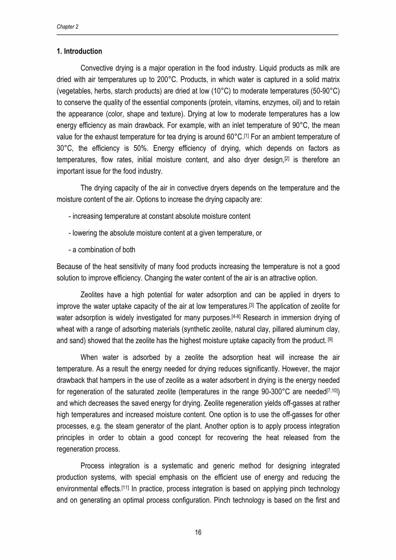
1. Introduction
Convective drying is a major operation in the food industry. Liquid products as milk are
dried with air temperatures up to 200°C. Products, in which water is captured in a solid matrix
(vegetables, herbs, starch products) are dried at low (10°C) to moderate temperatures (50-90°C)
to conserve the quality of the essential components (protein, vitamins, enzymes, oil) and to retain
the appearance (color, shape and texture). Drying at low to moderate temperatures has a low
energy efficiency as main drawback. For example, with an inlet temperature of 90°C, the mean
value for the exhaust temperature for tea drying is around 60°C.[1] For an ambient temperature of
30°C, the efficiency is 50%. Energy efficiency of drying, which depends on factors as
temperatures, flow rates, initial moisture content, and also dryer design,[2] is therefore an
important issue for the food industry.
The drying capacity of the air in convective dryers depends on the temperature and the
moisture content of the air. Options to increase the drying capacity are:
- increasing temperature at constant absolute moisture content
- lowering the absolute moisture content at a given temperature, or
- a combination of both
Because of the heat sensitivity of many food products increasing the temperature is not a good
solution to improve efficiency. Changing the water content of the air is an attractive option.
Zeolites have a high potential for water adsorption and can be applied in dryers to
improve the water uptake capacity of the air at low temperatures.[3] The application of zeolite for
water adsorption is widely investigated for many purposes.[4-8] Research in immersion drying of
wheat with a range of adsorbing materials (synthetic zeolite, natural clay, pillared aluminum clay,
and sand) showed that the zeolite has the highest moisture uptake capacity from the product. [9]
When water is adsorbed by a zeolite the adsorption heat will increase the air
temperature. As a result the energy needed for drying reduces significantly. However, the major
drawback that hampers in the use of zeolite as a water adsorbent in drying is the energy needed
for regeneration of the saturated zeolite (temperatures in the range 90-300°C are needed[7,10])
and which decreases the saved energy for drying. Zeolite regeneration yields off-gasses at rather
high temperatures and increased moisture content. One option is to use the off-gasses for other
processes, e.g. the steam generator of the plant. Another option is to apply process integration
principles in order to obtain a good concept for recovering the heat released from the
regeneration process.
Process integration is a systematic and generic method for designing integrated
production systems, with special emphasis on the efficient use of energy and reducing the
environmental effects.[11] In practice, process integration is based on applying pinch technology
and on generating an optimal process configuration. Pinch technology is based on the first and
Process Integration for Food Drying wirh Air Dehumidified by Zeolites
17
second laws of thermodynamics, which uses a minimum driving force for energy transfer called
pinch temperature.[12] The method has been widely used in various sectors and resulted in
significant energy reductions and lower environmental effects.[13-22] Based on the track record,
process integration offers potential for the development of efficient zeolite based drying systems.
This work concerns the use of zeolites in moderate temperature drying for food
applications. First, a zeolite drying system is compared with a conventional drying system by
using steady state mass and energy balances. Secondly, it is shown that compared to a
conventional dryer the energy efficiency of a zeolite dryer with process integration is higher. The
calculations are based on a dryer with an air flow of 1000 kg/hr. Although its concerns a small
dryer, the results on energy efficiency do not change for other scales; the heat exchanging area
follows from a linear scale-up.
2. Zeolite dryer versus conventional dryer
2.1 Zeolite drying system
Figure 2.1 presents the zeolite dryer system, which consists of an adsorber, heater,
dryer, and regeneration unit. The adsorber uses zeolite to reduce the humidity of the air to 10% of
its initial humidity. The air enters the adsorber at ambient temperature and due to the release of
the adsorption heat the air leaves the adsorber at a higher temperature. Before charging to the
dryer, air can be heated additionally to the required drying temperature using saturated steam
and returning the condensate to the steam supplying utility. The air is fed into the dryer where it
contacts the wet product and the sensible heat of the air is used to evaporate water. Because of
the low water content of the air, the water uptake capacity is higher and thus a lower air flow is
needed. Meanwhile, the saturated zeolite from the adsorber is dried in the regeneration unit to
obtain dry zeolite for reuse in the adsorption unit. The regeneration system uses hot air, heated
with steam, with a temperature in the range of 90-300oC. A higher temperature gives a better
regeneration. Dry zeolite is cooled down before feeding to adsorber by indirect cooling with cold
air. In this case a first step for energy recovery is already applied by using the exhaust air of the
dryer for regeneration. Even nearly saturated air from the dryer is after heating to 200-300°C
suitable for regeneration (RH<1%). The stream conditions used for the calculation are given in
Appendix 2.1. The calculations results (given in Table 2.1a) concern a small dryer with only 1000
kg air/hr, but results can be extrapolated linearly to larger systems. Note: in the picture a symbol
for a spray dryer unit is used, but any convective dryer can replace it.

Chapter 2
18
Figure 2.1: Dryer with zeolite dehumidified air; the numbers give the tags for the streams
Stream 13 also can be directly recycled by mixing with fresh air in order to minimize the
use of ambient air and to retain the energy in the dryer exhaust air. As a result the required heat
in heater 1 is reduced because the recycle temperature is higher than the ambient temperature.
In this way, the total energy consumption can be reduced. However, the heat required in Heater 2
increases due to higher water content that has to be released. The result of estimation can be
seen in Table 2.1b.
2.2 Conventional drying system
Figure 2.2 presents a conventional drying system in which the same wet material is dried.
The system consists of a heater to increase air from ambient temperature to the required drying
temperature, and a dryer to dry the product. The conditions for drying are given in Appendix 2.1.
Figure 2.2: Conventional dryer; the numbers give the tag for the streams
Dryer
Heater
Pd-in 3
Ahe,in
1 Ad-in 2
Pd-out
4
Ad-out 5
Steam
To utility
Aad-in
1
Pd-out
Aad-out 4
Dryer
Pd-in 3
12 Zr-out 8
Ar-in 9
Regenerator
Adsorber
Zad-out 5
Ar-out
10
Heater 1
Z,ad-in 2
Ad-in 6
Ahe-in 11
Heater 2
Ad-out
7
Steam
Steam
Cooler
Air
To utility
Cold Air
To utility
To utility
Aex
13

Process Integration for Food Drying wirh Air Dehumidified by Zeolites
19
2.3. Mass and energy balances
For the calculations both drying systems are split into sub systems. Steady-state models
for the subsystems, based on the conservation of mass and enthalpy are used. Assumptions for
the calculations are:
� adiabatic processes for the subunits,
� constant physical properties (density, specific heat),
� pressure drop is excluded from the calculations,
� operational pressure 1 bar,
� well mixed subsystems,
� in all cases the exhaust air of the dryer has a relative humidity of 40%,
� in the adsorption unit 90% of moisture content in the air is removed,
� at the exit of each unit air and solid material have the same temperature
� the enthalpy reference is 0°C
Values used for calculations are given in Table A1-1, Appendix 2.1.
a. Adsorber (see Figure 2.3)
Figure 2.3: Adsorber input-output streams
Assumptions
- Calculations are based on dry air and dry zeolite flows
- Dry air flow in equals dry air flow out: aout,ain,a FFF ==
- Dry zeolite flow in equals dry zeolite flow out : zout,zin,z FFF ==
The water mass balance is:
out,zzout,aain,zzin,aa XFYFXFYF +=+ (1)
The enthalpy balance for the adsorber is:
in,ain,aa T,Y,F
in,zin,zz T,X,F
Adsorber
out,zout,zz T,X,F
out,aout,aa T,Y,F
Air Zeolite

Chapter 2
20
adsout,zout,ain,zin,a HHHHH ++=+ (2)
)YHT)cYc((FH in,avin,av,pin,aa,pain,a ∆++= (3)
in,zw,pin,zz,pzin,z T)cXc(FH += (4)
)YHT)cYc((FH out,avout,av,pout,aa,paout,a ∆++= (5)
out,zw,pout,zz,pzout,z T)cXc(FH += (6)
zin,zout,zadsads F)XX(HH −∆= (7)
Physical constants and operational conditions are given Table A1-1, Appendix 2.1. The required
zeolite flow and outlet temperature of the adsorber are results of the calculations. Note: In the
calculation results not the dry air and zeolite flows are represented, but the wet air and zeolite
flows. Note: in the calculation results not the dry air and zeolite flows are represented, but the wet
air and zeolite flows. Mass flow of each stream contain dry material or air and moisture; see note
(*) in Tables 1a and 1b.
b. Regenerator
The mass and enthalpy balances for regenerator are almost equal to that of the adsorber.
However, here energy is required to release water from the zeolite.
out,zout,adesin,zin,a HHHHH +=−+ (8)
adsdes HH −= (9)
Those balances are used to calculate the temperature and air humidity of the outlet streams.
Analog equations as given for the adsorber are used.
c. Heater (see Figure 2.4)
Figure 2.4: Heater input-output streams
in,hein,aa T,Y,F out,hein,aa T,Y,F Heater
Qhe
from steam

Process Integration for Food Drying wirh Air Dehumidified by Zeolites
21
The aim of this calculation is to estimate required amount of external heat. The steam flow is not
considered since after transferring heat, it changes to condensate which is sent to steam boiler.
In the heater no mass exchange takes place; so only the enthalpy balance has to be considered.
The enthalpy balance for the heater is given as balance form:
out,ahein,a HQH =+ (10)
The inlet and outlet air enthalpy follow from the stream conditions. The required heat for the
heater is calculated.
d. Dryer (see Figure 2.5)
Figure 2.5: Dryer input-output streams
Assumptions
- Calculations based on dry air and product flows
- Dry air flow in equals dry air flow out: aout,ain,a FFF ==
- Dry product flow in equals dry product flow out : pout,pin,p FFF ==
In the dryer mass and energy exchange take place. The water balance using dry basis air and
product flow are as follows:
out,pout,pout,aain,ppin,aa XFYFXFYF +=+ (11)
satout,a Y.RHY = (12)
where satY represents the water vapor saturation line in the psychometric chart and
depends on outlet dryer temperature ( ),outdT , which follows from the enthalpy balance of dryer.
The balances are:
evapout,pout,ain,pin,a HHHHH ++=+ (13)
out,pw,pout,pp,ppout,p T)cXc(FH += (14)
pout,pin,pvevap F)XX(HH −∆= (15)
in,pw,pin,pp,ppin,p T)cXc(FH += (16)
in,ain,aa T,Y,F Dryer
in,pin,pp T,X,F
Air Product
out,pout,pp T,X,F
out,aout,aa T,Y,F

Chapter 2
22
Physical constants and operational conditions are given Table A1-1, Appendix 2.1. The
product moisture content leaving the dryer ( out,pX ) is set to 0.111 kg water/kg dry product, and
outlet temperature of product and air equals ( out,dout,aout,p TTT == ). The flow of dry product and
outlet dryer temperature are result of the calculations. The effect of product/air temperature on
product moisture at given relative humidity proved to be minimal and is neglected. Note: in the
calculation results not the dry air and zeolite flows are represented, but the wet air and zeolite
flows. Mass flow of each stream contain dry material or air and moisture; see note (*) in Tables
2.1a and 1b.
e. Cooler (see Figure 2.6)
Figure 2.6: Cooler input-output streams
The aim of this calculation is to estimate amount of heat to be removed in cooler. Here, cold air is
used to cool hot zeolite exiting regenerator. In this unit no mass exchange takes place; so only
the enthalpy balance has to be considered. The enthalpy balance for the cooler is as follows:
out,zcoin,z HQH += (17)
The inlet and outlet air enthalpy follow from the stream conditions. The required cooling capacity
is calculated.
2.4 Comparing zeolite and conventional drying system
The results for the zeolite and conventional drying systems are summarized in Table 2.1a
and Table 2.1b. The tables present the mass and energy flows at different points in the system
and temperature and moisture content of each flow.
in,coin,zz T,Y,F out,coout,zz T,Y,F
Cooler
Qco
transferred to cold air

Process Integration for Food Drying wirh Air Dehumidified by Zeolites
23
Table 2.1a: Results of drying with dehumidified air without recycle
Stream Number
Temperature oC
Moisture kg/kg
Wet Mass Flow kg/hr*
Enthalpy Flow (H) kJ/hr
1, Aad-in 25.00 0.0100 1000 49983 2, Zad-in 35.00 0.0000 45 1304 3, Pd-in 25.00 2.3333 21 1864 4, Aad-out 51.62 0.0010 991 53679 5, Zad-out 51.62 0.2000 54 3845 6, Ad-in 70.00 0.0010 991 71916 7, Ad-out 35.40 0.0150 1005 73192 8, Zr-out 141.19 0.0000 45 5259 9, Ar-in 300.00 0.0150 201 68551 10, Ar-out 141.19 0.0600 210 60900 11, Ahe-in 35.40 0.0150 201 14638 12, Pd-out 35.40 0.1111 7 588 13, Aex 35.40 0.0150 804 58553
461 HHQ ,he −= 18237
1192 HHQ ,he −= 53913
Total Heat required = 21 ,he,he QQ + 72150
28 HHQco −= 3955
Total heat removed= coQ− -3955 *Based on wet flow e.g: Aad-in = Fa (1+Ya,in)
Table 2.1b: Results of the conventional dryer
Stream Number
Temperature oC
Moisture kg/kg
Wet Mass Flow kg/hr*
Enthalpy Flow (H) kJ/hr
1, Ahe-in 25.00 0.0100 1212 60588 2, Ad-in 70.00 0.0100 1212 115638 3, Pd-in 25.00 2.3333 21 1864 4, Pd-out 41.72 0.1111 7 693 5, Ad-out 41.72 0.0216 1226 116809
12 HHQhe −= 55050
Total heat required 55050 *based on wet flow
As the zeolite system uses nearly dry air the wet bulb temperature of the air is about 6°C
below the wet bulb temperature for the conventional dryer. It gives some benefit for the energy
efficiency, but more important, the mean product temperature in the dryer will be lower and thus
degradation of product quality due to heat load is lower.
The drying capacity is related to the difference between the moisture content in inlet air
and for air with 40% relative humidity. The difference for the dehumidified air is larger than for the
fresh air and therefore the zeolite dryer needs about 20% less air than the conventional dryer.
Chapter 2
24
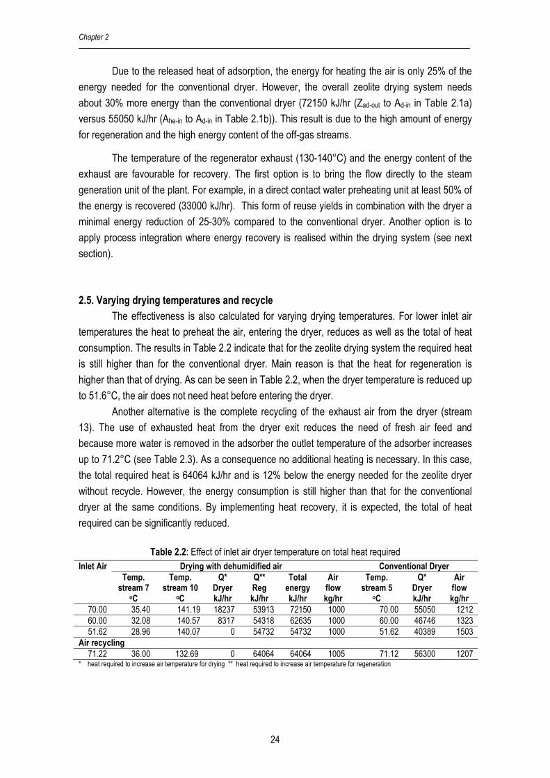
Due to the released heat of adsorption, the energy for heating the air is only 25% of the
energy needed for the conventional dryer. However, the overall zeolite drying system needs
about 30% more energy than the conventional dryer (72150 kJ/hr (Zad-out to Ad-in in Table 2.1a)
versus 55050 kJ/hr (Ahe-in to Ad-in in Table 2.1b)). This result is due to the high amount of energy
for regeneration and the high energy content of the off-gas streams.
The temperature of the regenerator exhaust (130-140°C) and the energy content of the
exhaust are favourable for recovery. The first option is to bring the flow directly to the steam
generation unit of the plant. For example, in a direct contact water preheating unit at least 50% of
the energy is recovered (33000 kJ/hr). This form of reuse yields in combination with the dryer a
minimal energy reduction of 25-30% compared to the conventional dryer. Another option is to
apply process integration where energy recovery is realised within the drying system (see next
section).
2.5. Varying drying temperatures and recycle
The effectiveness is also calculated for varying drying temperatures. For lower inlet air
temperatures the heat to preheat the air, entering the dryer, reduces as well as the total of heat
consumption. The results in Table 2.2 indicate that for the zeolite drying system the required heat
is still higher than for the conventional dryer. Main reason is that the heat for regeneration is
higher than that of drying. As can be seen in Table 2.2, when the dryer temperature is reduced up
to 51.6°C, the air does not need heat before entering the dryer.
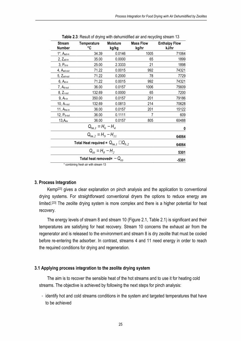
Another alternative is the complete recycling of the exhaust air from the dryer (stream
13). The use of exhausted heat from the dryer exit reduces the need of fresh air feed and
because more water is removed in the adsorber the outlet temperature of the adsorber increases
up to 71.2°C (see Table 2.3). As a consequence no additional heating is necessary. In this case,
the total required heat is 64064 kJ/hr and is 12% below the energy needed for the zeolite dryer
without recycle. However, the energy consumption is still higher than that for the conventional
dryer at the same conditions. By implementing heat recovery, it is expected, the total of heat
required can be significantly reduced.
Table 2.2: Effect of inlet air dryer temperature on total heat required Drying with dehumidified air Conventional Dryer Inlet Air
Temp. stream 7
oC
Temp. stream 10
oC
Q* Dryer kJ/hr
Q** Reg kJ/hr
Total energy kJ/hr
Air flow kg/hr
Temp. stream 5
oC
Q* Dryer kJ/hr
Air flow kg/hr
70.00 35.40 141.19 18237 53913 72150 1000 70.00 55050 1212 60.00 32.08 140.57 8317 54318 62635 1000 60.00 46746 1323 51.62 28.96 140.07 0 54732 54732 1000 51.62 40389 1503
Air recycling
71.22 36.00 132.69 0 64064 64064 1005 71.12 56300 1207 * heat required to increase air temperature for drying ** heat required to increase air temperature for regeneration
Process Integration for Food Drying wirh Air Dehumidified by Zeolites
25
Table 2.3: Result of drying with dehumidified air and recycling stream 13
Stream Number
Temperature °C
Moisture kg/kg
Mass Flow kg/hr
Enthalpy Flow kJ/hr
1*, Aad-in 34.39 0.0146 1005 71064 2, Zad-in 35.00 0.0000 65 1899 3, Pd-in 25.00 2.3333 21 1898 4, Aad-out 71.22 0.0015 992 74321 5, Zad-out 71.22 0.2000 78 7729 6, Ad-in 71.22 0.0015 992 74321 7, Ad-out 36.00 0.0157 1006 75609 8, Zr-out 132.69 0.0000 65 7200 9, Ar-in 350.00 0.0157 201 79186 10, Ar-out 132.69 0.0813 214 70628 11, Ahe-in 36.00 0.0157 201 15122 12, Pd-out 36.00 0.1111 7 609 13,Aex 36.00 0.0157 805 60488
461 HHQ ,he −= 0
1192 HHQ ,he −= 64064
Total Heat required = 21 ,h,he QQ + 64064
28 HHQco −= 5301
Total heat removed= coQ− -5301 * combining fresh air with stream 13
3. Process Integration
Kemp[23] gives a clear explanation on pinch analysis and the application to conventional
drying systems. For straightforward conventional dryers the options to reduce energy are
limited.[23] The zeolite drying system is more complex and there is a higher potential for heat
recovery.
The energy levels of stream 8 and stream 10 (Figure 2.1, Table 2.1) is significant and their
temperatures are satisfying for heat recovery. Stream 10 concerns the exhaust air from the
regenerator and is released to the environment and stream 8 is dry zeolite that must be cooled
before re-entering the adsorber. In contrast, streams 4 and 11 need energy in order to reach
the required conditions for drying and regeneration.
3.1 Applying process integration to the zeolite drying system
The aim is to recover the sensible heat of the hot streams and to use it for heating cold
streams. The objective is achieved by following the next steps for pinch analysis:
� identify hot and cold streams conditions in the system and targeted temperatures that have
to be achieved

Chapter 2
26
� configure temperature intervals and composite curves to determine the maximum energy
can be transferred, minimum hot and cold utility required and pinch point temperature
� match the possible hot and cold streams of the process to reduce external energy use
� estimate energy recovery by introducing a number of heat exchangers
Table 2.4: Hot and cold stream conditions for dehumidified air drying (Figure 2.1)
Source Target Stream
Stream Temperature oC
Stream Temperature oC
Heat capacity kJ/ oC hr
Q kJ/hr
Cold 1 11, Ahe-in 51.62 9 300 203.75 53913 Cold 2 4, Aad-out 35.40 6 70 992.01 18237
Total external heat required 72150
Hot 1 8, Zr-out 141.19 2 35 37.25 3955 Hot 2 10, Ar-out 141.19 exhaust 45 220.95 21254
Total heat released 25209
Table 2.4 shows that systems needs 72150 kJ/hr, while 25209 kJ/hr is released. With full
energy recovery minimally 46941 kJ/hr is needed, which is around 15% below the energy needed
for the conventional dryer. Streams 11 and 4, can be heated by using stream 8 and/or 10. By
matching these streams, it is expected that the main part of all potential energy can be recovered.
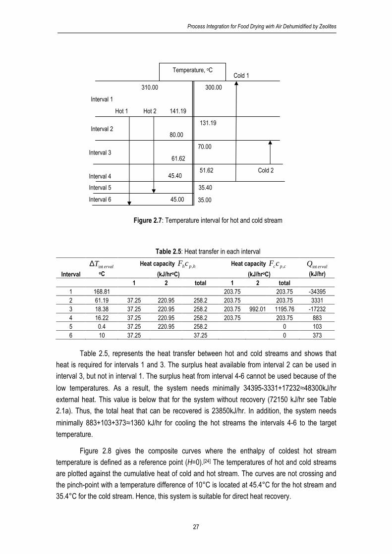
3.2. Identifying energy recovery from pinch analysis
First a scheme with the cold and hot streams and their temperature intervals is made
(see Douglas[24]). Using a minimal required driving force (∆T =10oC) yields the results in Figure
2.7, the temperatures for hot and cold stream are presented (see Figure 2.7). In each the interval,
heat transfer is given by the following equation:
[ ] i,ervalinti,cpci,hphi,ervalint T)cF()cF(Q ∆−= ∑ (18)
Process Integration for Food Drying wirh Air Dehumidified by Zeolites
27
Figure 2.7: Temperature interval for hot and cold stream
Table 2.5: Heat transfer in each interval
Interval
ervalTint∆
oC
Heat capacity hphcF ,
(kJ/hroC)
Heat capacity cpccF ,
(kJ/hroC)
ervalQint
(kJ/hr)
1 2 total 1 2 total
1 168.81 203.75 203.75 -34395 2 61.19 37.25 220.95 258.2 203.75 203.75 3331 3 18.38 37.25 220.95 258.2 203.75 992.01 1195.76 -17232 4 16.22 37.25 220.95 258.2 203.75 203.75 883 5 0.4 37.25 220.95 258.2 0 103 6 10 37.25 37.25 0 373
Table 2.5, represents the heat transfer between hot and cold streams and shows that
heat is required for intervals 1 and 3. The surplus heat available from interval 2 can be used in
interval 3, but not in interval 1. The surplus heat from interval 4-6 cannot be used because of the
low temperatures. As a result, the system needs minimally 34395-3331+17232≈48300kJ/hr external heat. This value is below that for the system without recovery (72150 kJ/hr see Table
2.1a). Thus, the total heat that can be recovered is 23850kJ/hr. In addition, the system needs
minimally 883+103+373≈1360 kJ/hr for cooling the hot streams the intervals 4-6 to the target
temperature.
Figure 2.8 gives the composite curves where the enthalpy of coldest hot stream
temperature is defined as a reference point (H=0).[24] The temperatures of hot and cold streams
are plotted against the cumulative heat of cold and hot stream. The curves are not crossing and
the pinch-point with a temperature difference of 10°C is located at 45.4°C for the hot stream and
35.4°C for the cold stream. Hence, this system is suitable for direct heat recovery.
141.19
Temperature, oC
300.00
131.19
Hot 1 Hot 2
Cold 2
Cold 1
80.00
70.00
51.62
61.62
35.40
45.40
35.00
Interval 1
Interval 2
Interval 3
Interval 4
Interval 5
45.00 Interval 6
310.00

Chapter 2
28
35
60
85
110
135
160
185
210
235
260
285
310
0 20000 40000 60000 80000
Enthalpy kJ/hr
Tem
pera
ture
°C
Hot Stream
Cold Stream
Figure 2.8: Composite curve of hot and cold stream
3.3. Heat exchanger network configuration
The hot and cold composite curves show that the possible matches are located above
the pinch point. Hot streams can be matched with cold stream when it has lower heat capacity
( c,pFc ≥ h,pFc ).[24]
Hot 2 cannot be optimally used to heat cold 1, while hot 1, with lowest heat capacity can
directly be used to heat either cold 1 or cold 2. In addition, cold 2 with highest heat capacity can
be matched to both hot 1 and 2. So, the heat exchanger network for heat recovery can be
generated in two ways. The first is a direct matching of cold 2 with hot 2, and cold 1 with hot 1
(see Figure 2.9). The second is splitting hot 2 in order to bring the heat capacity of the separate
streams below that of both cold streams. Now, the divided hot stream is matched with both cold
streams. The best solution can be found by evaluating the total quantity of energy that is
transferred, the required heat exchanger area, the amount of energy transferred per unit of area,
and the total of energy needed after integration.
3.3.1. Direct matching
The direct match is made of combining hot 2 with cold 2 and hot 1 with cold 1, as
presented in Figure 2.9 called as network 1.

Process Integration for Food Drying wirh Air Dehumidified by Zeolites
29
Figure 2.9: Heat exchanger configuration for a direct match (network 1)
Heat exchanger calculations based on the following assumptions were performed:
� a minimum temperature difference of 10oC,
� an overall gas-to gas heat transfer coefficient of 50 kJ/m2hr°C(=13.89 W/m2.°C) [25]
� an adiabatic process,
� constant physical properties (density, specific heat),
� counter current heat exchanger.
The used expressions are:
10+= in,cout,h TT (19)
)TT(cFQ in,hout,hh,phh −= (20)
0QQ i,ci,h =+∑ ∑ (21)
)TT(cFQ in,cout,cc,pci,c −= (22)
LMTDexci,hTUAQ ∆= (23)
in,cout,h
out,cin,h
in,cout,hout,cin,hLMTD
TT
TTln
)TT()TT(T
−−
−−−=∆ (24)
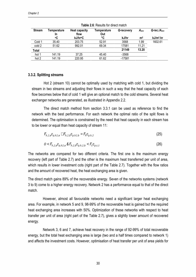
The results presented in Table 2.6 show the potential energy recovery. The total heat
transferred from hot streams to cold streams is 21149 kJ/hr, i.e. 89% of the available energy
identified from the pinch analysis (23850 kJ/hr). For the heat exchanger a total area of 13.20 m2
is required, and the total heat transferred per unit of area is 1602.61 kJ/m2hr. Around 11% of the
available heat in hot 1 and 2 is not recovered. Hot 2 has still potential for a higher degree of reuse
due to the high energy content and temperature.
Hot 1 141.19° C Hot 1
45°C
Cold 1 35.40° C
Cold 1
Hot 2
Cold 2, 51.62°C
Cold 2, 70°C
Hot 2 141.19°C
Chapter 2
30
Table 2.6: Results for direct match Stream Temperature
In oC
Heat capacity flow
kJ/hroC
Temperature Out °C
Q-recovery
kJ/hr
Aexc
m2
Q-rec./Aexc
kJ/m2.hr
Cold 1 35.40 203.75 52.91 3568 1.99 cold 2 51.62 992.01 69.34 17581 11.21
Total 21149 13.20
hot 1 141.19 37.25 45.40 -3568 hot 2 141.19 220.95 61.62 -17581
1602.61
3.3.2. Splitting streams
Hot 2 (stream 10) cannot be optimally used by matching with cold 1, but dividing the
stream in two streams and adjusting their flows in such a way that the heat capacity of each
flow becomes below that of cold 1 will give an optional match to the cold streams. Several heat
exchanger networks are generated, as illustrated in Appendix 2.2.
The direct match method from section 3.3.1 can be used as reference to find the
network with the best performance. For each network the optimal ratio of the split flows is
determined. The optimisation is constrained by the need that heat capacity in each stream has
to be lower or equal than heat capacity of stream 11:
22222 ,h,phb,h,pb,,ha,h,pa,,h cFcFcF =+ (25)
122220 ,c,pcb,,h,pb,,ha,h,pa,,h cFcF&cF << (26)
The networks are compared for two different criteria. The first one is the maximum energy
recovery (left part of Table 2.7) and the other is the maximum heat transferred per unit of area,
which results in lower investment cots (right part of the Table 2.7). Together with the flow ratios
and the amount of recovered heat, the heat exchanging area is given.
The direct match gains 89% of the recoverable energy. Seven of the networks systems (network
3 to 9) come to a higher energy recovery. Network 2 has a performance equal to that of the direct
match.
However, almost all favourable networks need a significant larger heat exchanging
area. For example, in network 5 and 9, 98-99% of the recoverable heat is gained but the required
heat exchanging area increases with 50%. Optimization of these networks with respect to heat
transfer per unit of area (right part of the Table 2.7), gives a slightly lower amount of recovered
energy.
Network 3, 6 and 7, achieve heat recovery in the range of 92-99% of total recoverable
energy, but the total heat exchanging area is large (two and a half times compared to network 1)
and affects the investment costs. However, optimisation of heat transfer per unit of area yields for

Process Integration for Food Drying wirh Air Dehumidified by Zeolites
31
network 7 a significant lower surface (even lower than the direct match), but now is the recovered
heat comparable to the direct match.
For maximum heat recovery and the lowest number of exchangers, network 4 is
preferred above networks 5, 8 or 9 due to the lower number of heat exchangers for the same
performance.
Table 2.7: Network performance for maximum energy recovery and maximum
energy transfer per unit of area Maximum Energy Recovered Maximum Q/A Network
Heat capacity
flow 10a/10b
kJ/oC hr
Heat
Recovered
kJ/hr
Aec
m2
Q/Aexc
kJ/m2hr
Heat capacity
flow 10a/10b
kJ/oC hr
Heat
Recovered
kJ/hr
Aec
m2
Q/Aec
kJ/m2hr
1
(direct
match)
-
21149
13.20
1602.61
21149
13.20
1602.61
2 107.20/113.75 21149 19.74 1071.31 107.20/113.75 21149 19.74 1071.31
3 197.20/23.75 21927 34.74 631.26 107.20/113.75 18395 15.08 1219.66
4 197.20/23.75 22733 19.35 1174.60 98.20/122.75 22225 17.05 1303.21
5 197.20/23.75 23533 19.48 1208.32 98.20/122.75 22675 15.92 1424.28
6 197.20/23.75 21927 34.89 628.27 98.20/122.75 20048 18.37 1091.18
7 197.20/23.75 23673 35.65 664.10 62.20/158.75 21080 12.90 1633.47
8 197.20/23.75 23704 19.37 1223.94 107.20/113.75 23106 17.41 1326.86
9 197.20/23.75 23773 19.33 1229.83 98.20/122.75 23293 17.20 1354.54
3.4. Network design and flexibility
The network aims to recover maximum energy by using the hot and cold stream
resources with minimum utility and low number of heat exchangers. The network is also expected
to be flexible to deal with different operation conditions of the sources and targets (i.e. other
temperature and flow levels). The suggested solutions, given in Appendix 2.2, make it possible to
operate at different levels for drying conditions.
Network 5, 6, 8 and 9 (see Appendix 2.2) can be used to recover energy for various
targeted drying temperatures. If a lower drying temperature reduces the heat demand of the
heater between adsorber and dryer, other heat recovery units still will use the energy. In
contrast, for networks 1, 2, 3, 4 and 7 the use of lower drying temperatures will result in extra
energy loss. Here the remaining heat from the hot stream is not used in other heat exchangers.
Network 1 is a clear example, if the temperature of cold 2 is 51.6oC (directly fed from adsorber to
dryer), the hot stream 2 is not recovered.
4. Discussion
4.1. Heat exchanger selection
Network 1, 4, 5 and 9 have the best characteristics in heat recovery and the required
heat exchanger (see Table 2.7). Combination with the criterion of flexibility network 5 and 9

Chapter 2
32
remain. Specifications of these two networks with respect to the hot and cold streams that leave
the networks are given in Table 2.8. In this table “Utility” presents the additional heat requirement
to reach the target conditions in the drying system.
Table 2.8: Condition of each stream leaving the network and total required utility Network Hot 1
oC
Hot 2
oC
Cold 1
oC
Cold 2
oC
Cold Utility
kJ/hr
Hot Utility
kJ/hr
5 45.4 50.83 61.41 70 1676 48613
9 61.16 47.09 62.59 70 1436 48377
Network 5 and 9, give a cold 2 stream that matches directly to the required target
temperature. These networks are able to reduce the temperature of hot 2 below 55oC, which is
close to the target value of 45oC. So a minimal cooling with cold air is necessary.
The zeolite dyer system with energy integration needs around of 48500 kJ/hr, which
contributes in the reduction of used energy (see Table 2.8). Compared to conventional dryer that
uses 55050 kJ/hr (as presented in Table 2.2), the zeolite dryer yields 12% higher energy
efficiency. Calculation results (not given) show also that with increasing moisture content of the
ambient air, the improvements increase.
4.2. Variation of drying temperatures
Table 2.2 shows that the required energy decreases for lower drying temperatures. Here,
the energy consumption of the integrated zeolite dryer is evaluated and compared to conventional
dryer for different drying temperatures. The calculations were done for network 9 because of its
high degree of energy recovery and flexibility. The results are presented in Table 2.9
The total energy recovery (except for total recycle), in the range 20700 to 23773 kJ/hr,
corresponds to energy savings of 12 to 14% compared to a conventional dryer. The remaining
heat in the exhaust air (hot 2) and zeolite stream (hot 1) cannot be reused further in the drying
system. At a temperature of 51.6°C the air preheating unit does not need additional heat. When a
total recycle is applied, the reduction of energy is also significant compared to that of a
conventional operating at the same conditions: the heat required is reduced with 18%.
The results of the calculations indicate that at the lower drying temperature, and for the
total recycle, the heat exchanger area required increases significantly to recover the heat. In
addition, for these operations, the air fed to the dryer does not require additional energy and now
hot 2 is maximally recovered for cold 1. As an alternative, exhausted energy can be used in other
parts of the production plant (e.g. steam boiler).

Process Integration for Food Drying wirh Air Dehumidified by Zeolites
33
Table 2.9: Maximum heat recovered at various temperature dryer conditions using network 9 Maximum Energy Recovered Temp.
Condition
oC
Heat Capacity
Flow 10a/10b
kJ/oC hr
Heat
Recovered
kJ/hr
Area
m2
Q/A
kJ/m2hr
Total Q
required
with recovery
kJ/hr
Q
Conventional
Dryer
kJ/hr
70 197.20/23.75 23773 19.33 1229.83 48377 55050
60 197.20/23.75 21782 26.10 834.67 40850 46746
51.62 197.20/23.75 20070 36.03 631.26 34662 40389
Air recycling
71.22 205.07/23.90 17777 36.47 487.46 46287 56300
5. Conclusions
The simulation calculations show that for medium temperature drying (50-70°C) of food
products, a direct zeolite drying system with partial air recycle cannot compete with a
conventional dryer. The main reason is the high energy content in the off-gas of the zeolite
regeneration system. However, the energy in the off-gas can be recovered, and then the zeolite
drying system is more energy efficient than a standard dryer.
For the three options for heat recovery the following conclusions were made:
− Direct use of the off-gas for a steam or power generation unit elsewhere on the plant. This
option is most efficient and energy consumption is 25-30% below that of a conventional
dryer.
− A direct match of the off-gas and hot zeolite for heating the drying air and regeneration
gains 89% of the recoverable heat and makes the zeolite system 10% more efficient than a
conventional dryer. However, changing the operation condition for drying affects the degree
of heat recovery.
− Pinch based process integration with a heat exchanger network gives several solutions. Now, up to 99% of the recoverable heat is gained and compared to the conventional dryer
the efficiency of the zeolite dryer increases up to 12-14%.
− For lower operating temperature the efficiency of the integrated zeolite dryer increases
slightly.
− A total recycle of drying air gives another step in the efficient improvement. The total of
heat required in this system is 18% below that of a conventional dryer.
− In the considerations for the choice of a network it is important to take the flexibility of the
heat exchanger network for drying at different temperature levels into account

Chapter 2
34
Acknowledgement
This work is supported by the staff training program (TPSDP) of the Chemical
Engineering Department of the Diponegoro University, Semarang, Indonesia.
References
1. Temple, S.J; van Boxtel, A.J.B. Modelling of fluidized bed drying of black tea. Journal of
Agriculture Engineering Research 1999, 74 (2), 203-212
2. Kudra, T. Energy aspect in drying. Drying Technology 2004, 22(5): 917-932
3. Tutova, E.G. Fundamentals of contact-sorption dehydration of labile materials. Drying
Technology 1988, 6(1),1-20
4. White, D.A.; Bussey, R.L. Water sorption properties of modified clinoptilolite. Separation
Purification Technology 1997, 11, 137-141
5. Zhu, W.; Gora L.; van den Berg, A.W.C; Kapteijn, F.; Jansen, J.C.; Moulijn, J.A. Water
vapour separation from permanent gases by a zeolite-4A membrane. Journal of Membrane
Science 2005, 253(1-2), 57-66
6. Liu, Y.; Leong, K.C. Numerical modeling of combined heat and mass transfer in the
adsorbent bed of a zeolite/water cooling system. Applied Thermal Engineering 2004, 24,
2359-2374
7. Liu, Y.; Leong, K.C. The effect of operating conditions on the performance of zeolite/water
adsorption cooling systems. Applied Thermal Engineering 2005, 25(10), 1403-1418
8. Anonymous. Siliporite data. CECA and ATO.
http://www.cecachemicals.com/sites/ceca/en/home.page (accessed September 26, 2006)
9. Revilla, G.O.; Velázquez, T.G.; Cortéz, S.L.; Cárdenas, S.A. Immersion drying of wheat
using Al-PILC, zeolite, clay and sand as particulate media. Drying Technology 2006, 24,
1033-1038
10. Jenkins, S.A.; Waszkiewicz, S.; Quarini, G.L.; Tierney, M.J. Drying saturated zeolite pellets
to assess fluidised bed performance. Applied Thermal Engineering 2002, 22, 861-871
11. Gundersen, T. A Process Integration Primer; SINTEF Energy Research, Dept. of Thermal
Energy and Hydro Power,Trondheim, Norway, 2002
12. Anonymous. Pinch Analysis: For The Efficient Use of Energy, Water, and Hydrogen;
Natural Resources, Verennes, Canada, 2003
13. Al-Riyami, B.A.; Klemeš J.; Perry S. Heat integration retrofit analysis of a heat exchanger
network of a fluid catalytic cracking plant. Applied Thermal Engineering 2001, 21,1449-
1487
14. Bošnjaković, F.; Knoche, K.F. Pinch analysis for cooling towers. Energy Conversion and Management 1998, 39(16-18), 1745-1752
15. Matijaševiae, L.; Otmaèiae, H. Technical Note: Energy recovery by pinch technology.
Applied Thermal Engineering 2004, 22,477-484
Process Integration for Food Drying wirh Air Dehumidified by Zeolites
35
16. Wang, Y.; Du, J.; Wu J., He, G.; Kuang, G.; Fan, X.; Yao, P.; Lu, S.; Li, P.; Tao, J.; Wan,
Y.; Kuang, Z.; Tian, Y. Application of total energy-integration in retrofitting an ammonia
plant. Applied Energy 2003, 76, 467-484
17. Herrera, A.; Islas, J.; Arriola, A. Pinch technology application in a hospital. Applied Thermal
Engineering 2003, 23,127-139
18. Dunn, R.F.; Bush, G.E. Using process integration technology for CLEANER production.
Journal of Cleaner Production 2001 , 23,1-23
19. Suaysompol, K.; Wood, R.M. Estimation of installed cost of heat exchanger networks.
International Journal of Production Economics 1993, 29, 303-312
20. Akahira, A.; Alam, A.K.C; Hamamoto, Y.; Akasiwa, A.; Kashiwagi, T. Mass recovery four-
bed adsorption refrigeration cycle with energy cascading. Applied Thermal Engineering
2005, 25(11-12),1764-1778
21. Kakaras, E.; Ahladas, P.; Syrmopoulos, S. Computer simulation studies for the integration
of an external dryer into a Greek lignite-fired power plant. Fuel 2002, 81 (5), 583-593
22. Van Deventer, H.C. Feasibility of energy efficient steam drying of paper and textile
including process integration. Applied Thermal Engineering 1997, 17, 1035-1041
23. Kemp, I.C. Reducing dryer energy use by process integration and pinch analysis. Drying
Technology 2005, 23, 2089-2104
24. Douglas, J.M. Conceptual Design of Chemical processes. McGraw-Hill Co, Intl. ed.;
Singapore, 1988
25. Perry, R.H.; Green D.W. Perry’s Chemical Engineers’ Handbook, 7th Intl. ed.; McGraw-Hill
Co, International edition, Singapore, 1998

Chapter 2
36
Appendix 2.1
Table A1-1: Applied values for constants and process conditions
Parameter Value
Flow of wet air to adsorber (kg/h) 1000
Air humidity to adsorber (kg water/kg dry air) 0.01
Temperature of air to adsorber (oC) 25
Humidity of air after adsorber (kg water/kg dry air) 0.001
Moisture at zeolite to adsorber (kg water/kg dry material) 0.000
Temperature of zeolite to adsorber (oC) 35
Moisture at zeolite after adsorber (kg water/kg dry material) 0.200
Temperature of wet product (oC) 25
Moisture of wet product (kg water/kg dry matter) 2.333
Moisture of dry product (kg water/kg dry matter) 0.110
Relative humidity of air after dryer (%) 40
Wet bulb temperature of dryer(oC) 24.5
Temperature of air to dryer (oC) 70
Temperature of air to regenerator (oC) 300
Operational pressure (bar) 1
Specific heat of dry air (kJ/kg oC) 1
Specific heat of water vapor (kJ/kg oC) 1.93
Specific heat of zeolite (kJ/kg oC) [6,7] 0.836
Specific heat of water (kJ/kg oC) 4.180
Specific heat of dry product (kJ/kg oC) 2.20
Heat of water adsorption/desorption (kJ/kg) [6,7] 3200
Heat of water evaporation (kJ/kg) 2500
Appendix 2.2: Network systems
Network 1
Hot 1 141.19° C Hot 1
45°C
Cold 1 35.40° C
Cold 1
Hot 2
Cold 2, 51.62°C
Cold 2, 70°C
Hot 2 141.19°C

Process Integration for Food Drying wirh Air Dehumidified by Zeolites
37
Network 2
Network 3
Hot 2 out
Cold 1 in
Tco1a
Cold 1
Hot2a Cph2a
Hot2b Cph2b
Tho2b
Tho2a 2
3
Hot 2 in
Hot 1
Cold 2 in
Cold 2
Hot 1 in 1
Hot 1 in
Hot 1
Cold 2 in Tcol1
Tco1a
Cold 1
Hot2a Cph2a
Hot2b Cph2b
Tho2b
Tho2a
1
2
3
4
Tho2cb
Hot 2
Cold 2
Hot2 in

Chapter 2
38
Network 4
Network 5
Cold 2
Cold 1 in
Tco1 1a
Cold 1
Hot 2a
Hot 2a1
Tho2b2
Tho2b1 4
5
2
Hot 2
Hot 1 in
Hot 1
3
Tcol 1b
Tcol2a
Cold 2 in
1
Hot 2 in
Hot 2a2
Hot1 in
Tco1a
Cold 1
Hot2a Cph2a
Hot2b Cph2b
Tho2b
Tho2a 3
4
Hot 2 in
Cold 1 in
Cold2
Hot 2
Hot1
1
2
Cold 2 in
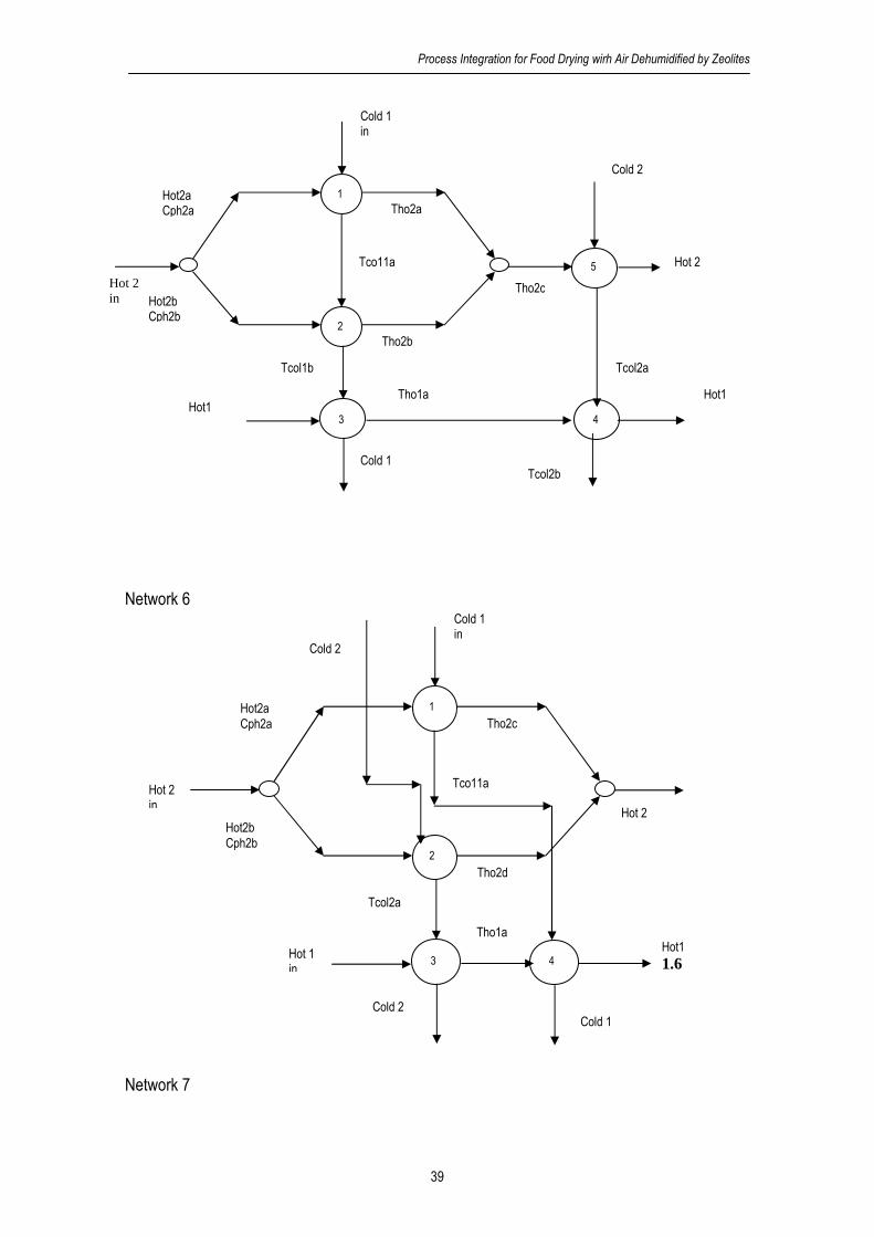
Process Integration for Food Drying wirh Air Dehumidified by Zeolites
39
Network 6
Network 7
Cold 1 in
Tco11a
Tho1a
Hot2a Cph2a
Hot2b Cph2b
Tho2d
Tho2c 1
2
Hot 2
Hot 1 in
Hot1 1.6 3
Cold 1
Tcol2a
4
Cold 2
Cold 2
Hot 2 in
Cold 2
Cold 1 in
Tco11a
Tho1a
Hot2a Cph2a
Hot2b Cph2b
Tho2b
Tho2a 1
2
5
Tho2cb
Hot 2
Hot1
Hot1
3
Tcol1b Tcol2a
Cold 1
4
Tcol2b
Hot 2 in

Chapter 2
40
Network 8
Network 9
Hot1 Tho1b
Hot1
Cold 2 in
Tcol1b
Tco1a Tco12a
Hot2a Cph2a
Hot2b Cph2b
Tho2a
Tho2b
1 2
3
5
Tho2d
Tho2c
Cold 1 in
Tcol2b
4
6
Hot 2 in
Hot 2
Tho1a
Cold 2 Cold 1
Cold 2 in
Cold 1 in
Tco11a
Tho1a
Hot2a Cph2a
Hot2b Cph2b
Tho2d
Tho2c 4
5
1
Hot 2
Hot 1 in
Hot 1 3
Tcol1b
Tcol2a
Cold 1
2
Cold 2
Hot 2 in
Chapter 3
Multistage Zeolite Drying
for Energy Efficient Drying
Published in: Drying Technology 2007, 25(6), 1053-1067
Chapter 3
42
Abstract
This work discusses the potential of three multistage zeolite drying systems (counter, co, and
cross-current) with a varying number of stages. The evaluation showed that for 2-4 stages with
heat recovery the efficiency of the systems ranges between 80-90%. Additionally, by introducing
a compressor, the latent heat in the exhaust air from the regenerator is recovered and used to
heat the inlet air for an additional drying stage. As a result, for the counter-current drying system
and compressor pressure 1.5-2 bar, a maximum energy efficiency of 120% is achieved which
results in halving the energy consumption compared to conventional drying systems.
Keyword: Drying, Efficiency, Multistage, Heat recovery, Zeolite
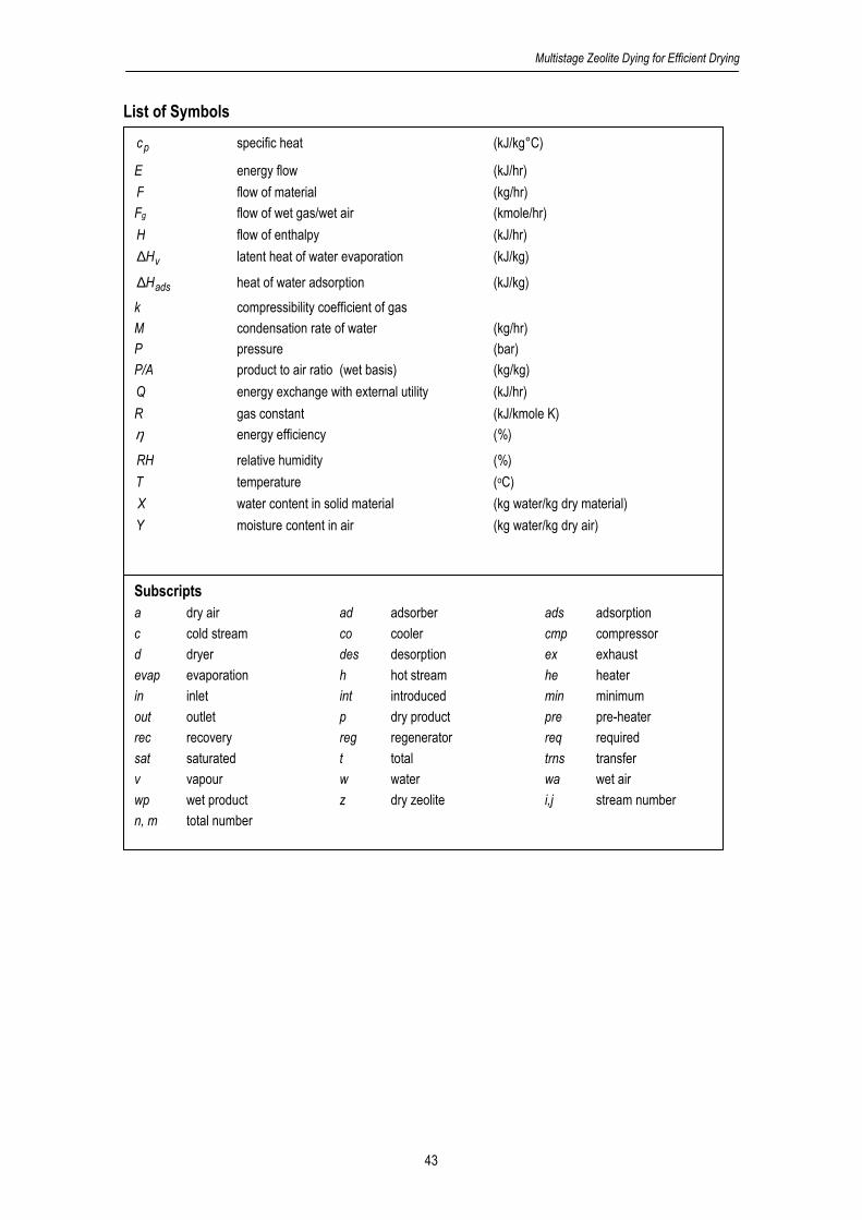
Multistage Zeolite Dying for Efficient Drying
43
List of Symbols
pc specific heat (kJ/kg°C)
E energy flow (kJ/hr)
F flow of material (kg/hr)
Fg flow of wet gas/wet air (kmole/hr)
H flow of enthalpy (kJ/hr)
vH∆ latent heat of water evaporation (kJ/kg)
adsH∆ heat of water adsorption (kJ/kg)
k compressibility coefficient of gas
M condensation rate of water (kg/hr)
P pressure (bar)
P/A product to air ratio (wet basis) (kg/kg)
Q energy exchange with external utility (kJ/hr)
R gas constant (kJ/kmole K)
η energy efficiency (%)
RH relative humidity (%)
T temperature (oC)
X water content in solid material (kg water/kg dry material)
Y moisture content in air (kg water/kg dry air)
Subscripts a dry air ad adsorber ads adsorption
c cold stream co cooler cmp compressor
d dryer des desorption ex exhaust
evap evaporation h hot stream he heater
in inlet int introduced min minimum
out outlet p dry product pre pre-heater
rec recovery reg regenerator req required
sat saturated t total trns transfer
v vapour w water wa wet air
wp wet product z dry zeolite i,j stream number
n, m total number
Chapter 3
44
1. Background
Zeolite drying systems have potential to increase the energy efficiency (i.e. total energy
required for evaporation of water divided by the consumed energy) for low and medium
temperature drying of food and other heat sensitive products. The principle of zeolite drying is
based on the removal of the water from the fresh air before feeding to the dryer. At the same time
the air is preheated due to the release of adsorption heat. As a result of these effects the driving
force for drying is enhanced, the required energy is reduced, and also a reduction of drying
temperature is possible. A preliminary evaluation[1] showed that a single stage zeolite drying
system can improve the energy efficiency with 10-18% in comparison to a conventional dryer.
Furthermore, the air flow required to dry the same amount of product is lower and might result in
smaller dryer equipment.
The disadvantage of zeolite drying is the high energy consumption and the high
temperature needed in the regenerator to release the water from the saturated zeolite. It limits the
improvement of the overall energy efficiency. For example, the release of 1 kg of water from a
zeolite type 13X, requires 3200 kJ. The release of water improves with increasing temperature[2]
and thus high regeneration temperatures are required. For 13X-zeolite temperatures above
120oC are preferred. Additionally, to make the zeolite drying system energy efficient 2-4 heat
exchangers are required to recover the energy in the exhaust air from the regenerator.[1] In
practice, it results in an increase of investment costs that may reduce the feasibility of the
system. Hence, improvement of energy efficiency is still a main issue to make a zeolite dryer
system competitive.
A promising alternative to improve the energy efficiency is the use of a multistage zeolite
drying system, where the product contacts zeolite dehumidified air in several units. Such system
consists of a number of dryers, adsorbers and regenerators in series. Before the first passage in
the first stage, the air is dehumidified. The exhaust air from the first dryer stage passes an
adsorber with zeolite which removes the water and increases the temperature due to the release
of adsorption heat. Then the air is fed into the second dryer stage etc. In this system the energy
content of the exhaust air is not lost, but upgraded and reused for drying at a higher temperature
and lower water content. The multistage drying results in a higher product capacity and higher
energy efficiency. Figure 3.1 part A, gives a schematic overview of the psychometric chart for the
zeolite dryer concept for a single and a multistage system, and shows that the drying
temperatures in the multistage system are lower. In this schematic presentation the water
adsorption from the air by the zeolite is about 75%, but in practice it can go up to 95%.

Multistage Zeolite Dying for Efficient Drying
45
Figure 3.1: A. Comparison of a single stage and a multistage zeolite dryer. B. Comparison of a single
stage and multistage conventional dryer.[3,4] Fresh air is fed to the system at position 0. After adsorption
and/or heating position 1 is reached for the multistage systems and 1’ for the single stage systems. From
this point the multistage systems continue with drying, adsorption or heating along the path 1-2-3 etc until
6. The single stage system continues to 2’.
The concept of multistage drying, where the energy of the exhaust air is reused has been
proposed for non-zeolite drying systems.[3,4] To get a better driving force in the next stage
exhaust air from a stage is re-heated to lower the relative humidity and to increase the
temperature. Figure 3.1 part B represents the comparison of a single stage and a multistage
conventional dryer.[3,4] Important advantage of this multistage system is that high air temperatures
in inlet air are avoided and the air flow is below that for a standard dryer.
The multistage dryer system provided important benefits compared to conventional single
dryer systems.[5] The evaluation showed that the operational cost of the multistage dryer
competes with a single-stage dryer at longer amortization time.[4] The best improvement of
energy efficiency was achieved at operational temperatures below 100oC for 2-4 drying stages
with around 10% energy saving but the improvement is not significant for high temperature
drying.[6]
According to these results, it can be concluded that multistage drying has potential to
improve efficiency and to reduce operational costs. The disadvantage of the conventional
multistage drying system is that the water content in the air increases in each drying stage. To
compensate for this effect the temperature in the sequence of drying stages has to be increased.
For heat sensitive products such as herbal medicines and food, the increasing temperature and
drying time are not desirable since it reduces product qualities as color, essential oil content,
structure (e.g. starch) and chemical composition.[7] Furthermore, the multistage conventional
dryer cannot improve the efficiency in high temperature drying significantly.[6]
Temperature
Humidity
Multistage 0-1-2-3-5-6
A
2
4
6
Single stage (0-1’-2’)
0
2’
1’ 1
3
5
Humidity
1
4
6
Temperature
B
Single stage (0-1’-2’)
0 1’
2’ adsorption
heating
drying
3 2
Multistage 0-1-2-3-5-6 5

Chapter 3
46
These limitations can be overcome by using a multistage zeolite drying system. Here the
water in the humid air from each drying stage is adsorbed by contacting zeolite, while at the same
time the temperature increases. The driving force after passing the zeolite bed increases so that
drying can take place at moderate temperatures. Although the drying process becomes efficient
by using the zeolite, regeneration can still limit the gain in efficiency. The objective of this paper is
to evaluate multistage zeolite drying systems together with the regeneration systems and
additional heat recovery. Cross, counter and co-current drying are considered and all the systems
are equipped with heat recovery units. The energy efficiency, product to air ratio, and complexity
of the process based on the number of stages are considered as performance indicators in the
evaluation.
2. Methodology
2.1. Process Objective
The aim is to evaluate the performance of multistage zeolite drying for heat sensitive
products with respect to the following criteria:
1. energy efficiency,
2. product to air ratio, and
3. complexity of the process.
As the energy consumption of drying is high and because the costs of energy are
expected to increase in the next decades, improvement of energy efficiency is considered as the
main indicator. The product to air ratio is a measure for the amount of air required to dry the
product and affects both the size of equipment and energy required to heat the air. Complexity is
important since it will affect the investment cost to establish the system.
2.2. Process configurations
Three configurations to improve the performance of zeolite dryers are considered:
counter-current, co-current and cross-current (see Appendix 3.1). In counter-current multistage
zeolite drying (see Figure A1-1, Appendix 3.1) the product is fed at the last stage of the dryer
series. Meanwhile, after passing an adsorber with zeolite, the inlet air is used for the first drying
stage. The humidified air leaving this stage contacts the following adsorber where the humidity
decreases and the temperature increases. Then the air is fed to the next drying stage. This
process is repeated several times. At each stage the zeolite is continuously regenerated by
exchange of zeolite between adsorber and regenerator. The exhaust air of each regenerator is
reheated and used for the next regeneration unit. In this system, the dried product is obtained in
the first stage, while air leaves the system in the last dryer stage.
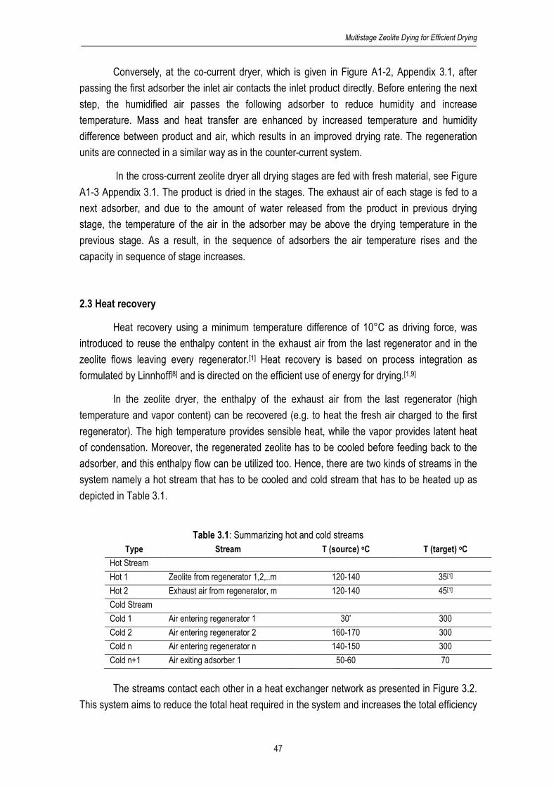
Multistage Zeolite Dying for Efficient Drying
47
Conversely, at the co-current dryer, which is given in Figure A1-2, Appendix 3.1, after
passing the first adsorber the inlet air contacts the inlet product directly. Before entering the next
step, the humidified air passes the following adsorber to reduce humidity and increase
temperature. Mass and heat transfer are enhanced by increased temperature and humidity
difference between product and air, which results in an improved drying rate. The regeneration
units are connected in a similar way as in the counter-current system.
In the cross-current zeolite dryer all drying stages are fed with fresh material, see Figure
A1-3 Appendix 3.1. The product is dried in the stages. The exhaust air of each stage is fed to a
next adsorber, and due to the amount of water released from the product in previous drying
stage, the temperature of the air in the adsorber may be above the drying temperature in the
previous stage. As a result, in the sequence of adsorbers the air temperature rises and the
capacity in sequence of stage increases.
2.3 Heat recovery
Heat recovery using a minimum temperature difference of 10°C as driving force, was
introduced to reuse the enthalpy content in the exhaust air from the last regenerator and in the
zeolite flows leaving every regenerator.[1] Heat recovery is based on process integration as
formulated by Linnhoff[8] and is directed on the efficient use of energy for drying.[1,9]
In the zeolite dryer, the enthalpy of the exhaust air from the last regenerator (high
temperature and vapor content) can be recovered (e.g. to heat the fresh air charged to the first
regenerator). The high temperature provides sensible heat, while the vapor provides latent heat
of condensation. Moreover, the regenerated zeolite has to be cooled before feeding back to the
adsorber, and this enthalpy flow can be utilized too. Hence, there are two kinds of streams in the
system namely a hot stream that has to be cooled and cold stream that has to be heated up as
depicted in Table 3.1.
Table 3.1: Summarizing hot and cold streams
Type Stream T (source) oC T (target) oC
Hot Stream
Hot 1 Zeolite from regenerator 1,2,..m 120-140 35[1]
Hot 2 Exhaust air from regenerator, m 120-140 45[1]
Cold Stream
Cold 1 Air entering regenerator 1 30* 300
Cold 2 Air entering regenerator 2 160-170 300
Cold n Air entering regenerator n 140-150 300
Cold n+1 Air exiting adsorber 1 50-60 70
The streams contact each other in a heat exchanger network as presented in Figure 3.2.
This system aims to reduce the total heat required in the system and increases the total efficiency

Chapter 3
48
by a lower amount of energy for the heating and a lower amount of cold utility for cooling. Due to
the small zeolite flow (ratio zeolite flow and air flow is 1:20), the zeolite flows from each
regenerator are mixed in one stream (hot 1) to minimize the number of heat exchangers. The
amount of heat recovery is estimated by summing the heat transferred in each heat exchanger
including sensible and latent heat, see equation 1 and 2.
Figure 3.2:Heat exchanger network
vji,wmin
ji,c
ji,h
ji,h,p
ji,hj,i,trns HM))TT(T(cFQ ∆+∆+−= (1)
∑∑= =
=n
1i
m
1j
j,i,trnsrec QQ (2)
2.4. Model Development
All the systems are simulated using steady-state mass and energy balance equations for
each operational unit as given in Figure 3.3. The model is developed by considering several
assumptions: the air is an ideal gas, relative humidity of the exhaust air from each dryer stage is
40%, the process is adiabatic and is considered as a well-mixed system, the efficiency of zeolite
to adsorb water is 90% and the physical properties (specific heat, density etc) are constant. The
models of each unit given in previous work of Djaeni et al[1] are presented in Appendix 3.2. The
models are based on the dry zeolite, air and product flows.
cold 1
cold Utility
cold n
hot 1 hot 2 hot
Utility
Target temperature
Target temperature
= Heat Exchanger
Zeolite from Regenerator n
Zeolite from Regenerator 1
Zeolite from Regenerator 2
1,1 1,2
2,1 2,2
n,1 n,2

Multistage Zeolite Dying for Efficient Drying
49
The values of the input variables, the used constants, and the stream notations for the
calculations are given in Table A2-1, Appendix 3.2. The resulting output variables are calculated
from mass and energy balances. These calculations are applied for each stage.
Figure 3.3: Operational units and their interconnection in co-current multistage zeolite dryer
2.5. Definition of evaluation criteria
The performance evaluation uses the following criteria:
a. Energy efficiency (%)
Energy efficiency is defined as the heat required for evaporating the amount of removed
water divided by total of heat introduced to the system:
%100Q
H
req
t,evap=η (3)
vn,out,p1,in,pt,pt,evap H)XX(FH ∆−= (4)
recintreq QQQ −= (5)
Dryer 1
Adsorber 1
Regenerator 1
Heater 1
Pre-heater
Cooler 1
Zeolite
Air Regenerator
Air dryer
Zeolite
Air dryer
Product
Stage 1 Dryer 2
Adsorber 2
Regenerator 2
Heater 2
Zeolite
Air Regenerator
Air dryer
Zeolite
Air dryer
Product
Stage 2 Product
Air dryer
Air Regenerator
To next Stage
To next Stage
Air
Zeolite
Product
Cooler 2

Chapter 3
50
b. Product to air ratio
This indicator represents the mass efficiency of the used air. Higher air flows require
more heating energy. Moreover, a higher product to air ratio can be profitable for the dimensions
of the equipment.
The product to air ratio is based on the total flow of product entering the zeolite dryer
system (see equation A2-17 to A2-19, Appendix 3.2).
t,wa
t,wp
F
F)A/P( = (6)
c. Complexity of configuration
An increasing number of stages will make the system more complex since more
operational units have to be used and the number of flows increases. The energy efficiency has
to be weighted with the complexity. It is expected that by extending the number of stages, the
efficiency will increase. However, at certain point the efficiency improvement is marginal while the
complexity still increases.
3. Result and Discussion
Multistage drying enhances the drying efficiency. Nevertheless heat recovery remains
also an essential step in improving the efficiency and both aspects have to be combined. In this
section the advantages of the multistage system will be qualified first and then the possibilities to
enhance the efficiency will be discussed in the following sub sections.
3.1. Basic results for multistage zeolite drying
Table 3.2 presents the results for the multistage drying systems. For all cases, extending
the dryer system increases the efficiency and product to air ratio. Without heat recovery the
efficiency achieves 67-72% at 4 stages (see column 6 row 5, 8, 11). The counter-current dryer
achieves the highest performance. Furthermore, the product to air ratio in the counter-current is
the highest which implies the most efficient usage of air. Without heat recovery the efficiency of
counter-current dryer ranges from 59 to 72%, and becomes 80-90% with heat recovery using a
heat exchanger network as presented in section 2.3. This achievement is significant compared to
the single stage zeolite dryer with heat recovery which achieves a total efficiency of 70-72%.[1]
The other process configurations give different efficiency results. For the cross-current
dryer, the air from the adsorber contacts always fresh product. The total product that is dried is
the sum of each stage. The advantage of this configuration is that it can be composed easily

Multistage Zeolite Dying for Efficient Drying
51
since the stages are independent on the other stage. As a result every stage has the inlet fresh
feed as independent variable that can be used to control the process. However, since the air
conditions vary in each stage, the equipment size in every stage can be different.
In the co-current system, the input air contacts the fresh feed in the first dryer and both
streams go in the same direction through the system. The driving force between product and air
(temperature and humidity) decreases along the stages. As a result, more heat and air is required
for drying. As given in Table 3.2, the product capacity and the efficiency of co-current dryer are
the lowest.
In the counter-current dryer, the air and product flows are in the opposite direction; fresh
product is contacted with the air in the last stage of adsorbers (see Figure A1-1, Appendix 3.1).
The advantage of this system is the ability to use the air from last stage to preheat fresh product.
Furthermore, the heat and mass transfer in every stage is enhanced which is reflected by the
enhanced product to air ratio and energy efficiency. The efficiency of counter-current is the
highest and goes up to 88%, for a three stage system with heat recovery.
In conclusion, the counter-current dryer is the most favorable alternative. The difference
between a three and four stage system is moderate and will probably not justify the extended
equipment costs.
Table 3.2: Performance of multistage zeolite dryer
Options
Stages
number
P/A
(kg/kg)
Heat
supplied
(kJ/hr)
Heat
used
(kJ/hr)
Efficiency
without heat
recovery
(%)
Heat
recovered
(kJ/hr)
Efficiency
with heat recovery
(%)
Conventional Dryer 1 0.018 55050 35000 63.6 -
63.6
1-stage zeolite with
heat recovery 1 0.021 72150 35000 48.6 23000
72
Cross-current 2 0.044 123644 73000 59.5 33022 80.5
3 0.070 174213 112594 64.6 37998 82.6
4 0.090 228627 155213 67.9 42856 83.5
Co-current 2 0.042 123644 70000 56.6 33472 77.6
3 0.066 173094 110000 63.5 38461 81.7
4 0.090 225618 150000 66.5 43271 82.2
Counter-current 2 0.044 123644 73000 59.0 32698 80.2
3 0.070 168429 116000 68.8 36894 88.1
4 0.095 218359 158500 72.5 42261 90.01
3.2. Heat recovery potential
The forgoing results show that the efficiency of the zeolite dryer is about 69% by using a
three stage counter-current dryer without energy recovery. The energy efficiency for this system
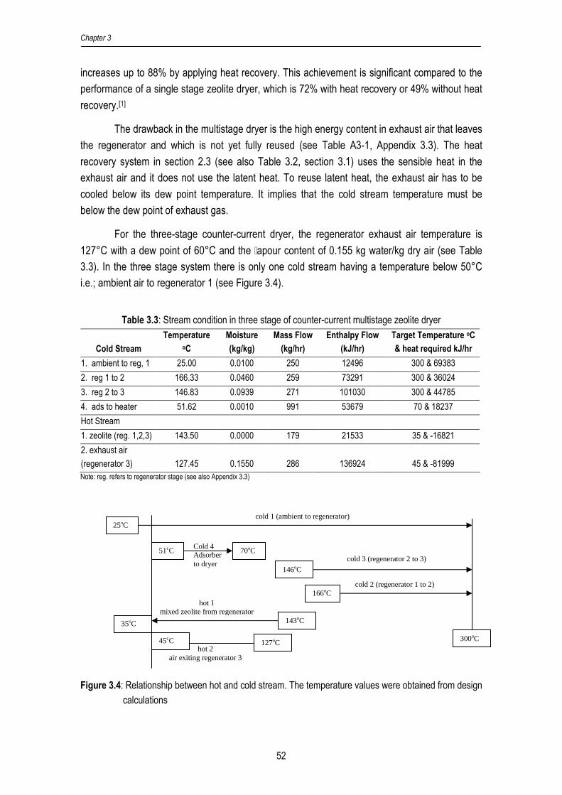
Chapter 3
52
increases up to 88% by applying heat recovery. This achievement is significant compared to the
performance of a single stage zeolite dryer, which is 72% with heat recovery or 49% without heat
recovery.[1]
The drawback in the multistage dryer is the high energy content in exhaust air that leaves
the regenerator and which is not yet fully reused (see Table A3-1, Appendix 3.3). The heat
recovery system in section 2.3 (see also Table 3.2, section 3.1) uses the sensible heat in the
exhaust air and it does not use the latent heat. To reuse latent heat, the exhaust air has to be
cooled below its dew point temperature. It implies that the cold stream temperature must be
below the dew point of exhaust gas.
For the three-stage counter-current dryer, the regenerator exhaust air temperature is
127°C with a dew point of 60°C and the `apour content of 0.155 kg water/kg dry air (see Table
3.3). In the three stage system there is only one cold stream having a temperature below 50°C
i.e.; ambient air to regenerator 1 (see Figure 3.4).
Table 3.3: Stream condition in three stage of counter-current multistage zeolite dryer
Cold Stream
Temperature
oC
Moisture
(kg/kg)
Mass Flow
(kg/hr)
Enthalpy Flow
(kJ/hr)
Target Temperature oC
& heat required kJ/hr
1. ambient to reg, 1 25.00 0.0100 250 12496 300 & 69383
2. reg 1 to 2 166.33 0.0460 259 73291 300 & 36024
3. reg 2 to 3 146.83 0.0939 271 101030 300 & 44785
4. ads to heater 51.62 0.0010 991 53679 70 & 18237
Hot Stream
1. zeolite (reg. 1,2,3) 143.50 0.0000 179 21533 35 & -16821
2. exhaust air
(regenerator 3) 127.45 0.1550 286 136924 45 & -81999 Note: reg. refers to regenerator stage (see also Appendix 3.3)
Figure 3.4: Relationship between hot and cold stream. The temperature values were obtained from design
calculations
25oC cold 1 (ambient to regenerator)
51oC
146oC
166oC
70oC Cold 4 Adsorber to dryer
cold 3 (regenerator 2 to 3)
cold 2 (regenerator 1 to 2)
hot 1 mixed zeolite from regenerator
hot 2 air exiting regenerator 3
143oC
127oC
35oC 52?
300oC 45oC 52?
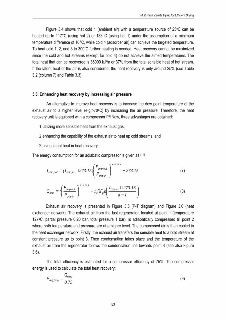
Multistage Zeolite Dying for Efficient Drying
53
Figure 3.4 shows that cold 1 (ambient air) with a temperature source of 25oC can be
heated up to 117°C (using hot 2) or 133°C (using hot 1) under the assumption of a minimum
temperature difference of 10°C, while cold 4 (adsorber air) can achieve the targeted temperature.
To heat cold 1, 2, and 3 to 300°C further heating is needed. Heat recovery cannot be maximized
since the cold and hot streams (except for cold 4) do not achieve the aimed temperatures. The
total heat that can be recovered is 36000 kJ/hr or 37% from the total sensible heat of hot stream.
If the latent heat of the air is also considered, the heat recovery is only around 25% (see Table
3.2 (column 7) and Table 3.3).
3.3. Enhancing heat recovery by increasing air pressure
An alternative to improve heat recovery is to increase the dew point temperature of the
exhaust air to a higher level (e.g;>70oC) by increasing the air pressure. Therefore, the heat
recovery unit is equipped with a compressor.[10] Now, three advantages are obtained:
1.utilizing more sensible heat from the exhaust gas,
2.enhancing the capability of the exhaust air to heat up cold streams, and
3.using latent heat in heat recovery
The energy consumption for an adiabatic compressor is given as:[11]
1527315273
1
.P
P).T(T
k/)k(
in,cmp
out,cmp
in,cmpout,cmp −
+=
−
(7)
−+
−
=
−
1
152731
1
k
.TkRF)
P
P(Q
in,cmp
g
k/)k(
in,cmp
out,cmp
cmp (8)
Exhaust air recovery is presented in Figure 3.5 (P-T diagram) and Figure 3.6 (heat
exchanger network). The exhaust air from the last regenerator, located at point 1 (temperature
127oC, partial pressure 0.20 bar, total pressure 1 bar), is adiabatically compressed till point 2
where both temperature and pressure are at a higher level. The compressed air is then cooled in
the heat exchanger network. Firstly, the exhaust air transfers the sensible heat to a cold stream at
constant pressure up to point 3. Then condensation takes place and the temperature of the
exhaust air from the regenerator follows the condensation line towards point 4 (see also Figure
3.6).
The total efficiency is estimated for a compressor efficiency of 75%. The compressor
energy is used to calculate the total heat recovery:
750.
QE
cmp
cmp,req = (9)
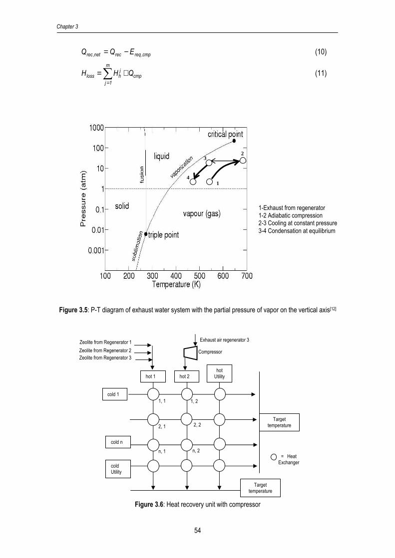
Chapter 3
54
cmp,reqrecnet,rec EQQ −= (10)
cmp
m
1j
jhloss QHH +=∑
=
(11)
Figure 3.5: P-T diagram of exhaust water system with the partial pressure of vapor on the vertical axis[12]
Figure 3.6: Heat recovery unit with compressor
cold 1
cold Utility
cold n
hot 1 hot 2 hot
Utility
Target temperature
Target temperature
= Heat Exchanger
Zeolite from Regenerator 3
Zeolite from Regenerator 1
Zeolite from Regenerator 2
Exhaust air regenerator 3
Compressor
1, 1 1, 2
2, 1 2, 2
n, 1 n, 2
1-Exhaust from regenerator 1-2 Adiabatic compression 2-3 Cooling at constant pressure 3-4 Condensation at equilibrium
1
2 3
4

Multistage Zeolite Dying for Efficient Drying
55
The calculation results, given in Table 3.4 column 5, show that with the implementation of
a compressor the recovered energy increases drastically. However, after counting the energy
used by the compressor the improvement of energy efficiency is cancelled (see Table 3.4 column
7). The heat required to heat the cold stream from its source up to 10oC below the hot stream
source is not enough. The reasons for the limitation are the low flows and high target temperature
for cold 1,2, 3 (see Figure 3.4). Moreover, cold 4 (air from adsorber to heater) needs not much
heat since this flow has to be heated up from 50oC to 70oC. As a result, the latent heat of vapor
condensation in hot 2 cannot be exploited maximally. Thus, the use of a compressor in the
system is not yet effective for the energy efficiency.
A meaningful alternative is, to reuse the heat in exhaust air from heat exchanger network
to heat other cold streams in the plant, for example boiler water or ambient air for another dryer
unit with a higher flow and lower temperature source. It is expected that in this way more heat can
be recovered.
Table 3.4: The efficiency of a three stage counter-current multistage zeolite dryer at various pressures
Pcmp,out
Bar
Dew Point*
exhaust air
oC
Hloss
kJ/hr
(3)
Ereq,cmp
kJ/hr
(4)
Qrec
kJ/hr
(5)
Qrec,net
kJ/hr
(5)-(4)
Efficiency
%
1.00 60.20 158457 0 36894 36894 88.2
1.50 69.24 173815 20477 50558 30081 83.8
2.00 76.01 185842 36513 62911 26398 81.7
2.50 81.47 195877 49893 73216 23323 79.9
3.00 86.07 204564 61476 82138 20662 78.5
3.50 90.07 212270 71751 90053 18302 77.3
4.00 93.62 219225 81024 97132 16108 76.2
4.50 96.81 225585 89504 103556 14052 75.1
5.00 99.72 231457 97333 109488 12155 74.2
5.50 102.40 236924 104623 115010 10387 73.4
*Interpolated few Figs. 2-4, page 2-90, Perry[11]
3.4. Reusing the exhaust air for an additional dryer
Despite the results of section 3.3 there is still potential to recover the latent heat of the
vapor in the compressed exhaust air from the heat exchanger network. It was realized by
extension of the network with one extra heat exchanger to heat ambient air for an extra drying
unit which can be used in the sequence of dryers of the multistage system. The temperature of
the air for this extra unit is then increased from 25°C (ambient) to a temperature 10°C below the
exhaust stream source (see section 2.3).

Chapter 3
56
In Figure 3.7, the cold streams from the multistage zeolite dryer are matched with hot
streams in the heat recovery unit. The exhaust air from the last regenerator (hot 2) is compressed
before entering the heat recovery unit. The zeolite flow (hot 1) is recycled to the multistage zeolite
dryer system. Finally, the exhaust air from the last regenerator (hot 2) contacts another cold
stream of fresh ambient air in the additional heat exchanger before purging to environment. The
total heat that can be recovered in the extra heat recovery unit is evaluated at various air
pressures; see Table 3.5.
Figure 3.7: Extended drying system with one extra drying stage and one heat exchanger to maximize heat
recovery
Table 3.5: Heat recovered for additional dryer unit Exhaust air after HRU 1 Exhaust Air after extra HRU 45°C
P
bar T
source oC
Y kg water/kg
dry air
Enthalpy kJ/hr (4)
P
bar Y target
kg water/kg dry air
Enthalpy kJ/hr (7)
Heat Recovered
kJ/hr (4)-(7)
1.0 63.35 0.1550 116311 0.9 0.0654 53017 63295 1.5 70.06 0.1550 118005 1.3 0.0421 38112 80358 2.0 76.44 0.1518 117680 1.7 0.0312 31119 87272 2.5 81.67 0.1491 117407 2.1 0.0248 27021 91288 3.0 86.03 0.1468 117142 2.5 0.0206 24327 93876 3.5 89.79 0.1450 116958 2.9 0.0176 22418 95739 4.0 93.11 0.1434 116840 3.3 0.0154 20994 97170 4.5 96.10 0.1420 116766 3.7 0.0137 19891 98312 5.0 98.81 0.1408 116705 4.1 0.0123 19011 99235 5.5 101.29 0.1397 116634 4.5 0.0112 18293 99974
Table 3.5 presents in the last column the total heat that can be recovered from the
compressed air in the extra heat recovery unit (HRU). For the calculations it was assumed that
the air was cooled down in a counter current exchanger to 45°C, which refers to previous work.[1]
Wet product
Multistage Zeolite Dryer System
HRU 1
Extra HRU
Utility Exhaust Air
Zeolite
Zeolite Dry
product Heated cold streams
Ambient Air
Cold Streams
Exhaust Air
Exhaust Air
Hot ambient air for extra dryer
Ambient air
Extra drying stage
Humidified air
Exhaust Air

Multistage Zeolite Dying for Efficient Drying
57
The air flow from the HRU 1 was 247 kg dry air/hr and the water content of the air is around 0.150
kg water/kg air. The pressure drop over the extra heat recovery unit below 0.7 bar is acceptable.
The heat recovery potential increases with compressed air pressure due to the
increasing amount of condensed vapor. However, to generate higher pressures more energy is
used by the compressor (see Table 3.4). So there will be an optimum for the compressor
pressure. If the additional dryer operates at 60% drying efficiency, the energy efficiency of the
total system increases drastically (see Table 3.6). The total efficiency for all pressures exceeds
100% since the system exploits heat from the condensing vapor in regenerator exhaust air. An
optimum efficiency energy efficiency of 120% is achieved at 1.5-2.0 bar. This result is obtained
when the ambient air flow in the range of 2000-2300 kg/hr (wet basis) is heated to 60-65oC.
Table 3.6: Total energy efficiency with additional dryer
Pcmp,out
bar
Heat recovered
from exhaust*
kJ/hr (2)
Heat used
in additional dryer
kJ/hr (3)=0.6* (2)
Heat used in three
stage zeolite
kJ/hr (4)**
Total required
with compressor
kJ/hr (5)
New energy
efficiency, %
=100%*((3)+(4))/(5)
1.0 63295 37977 116000 131535 117
1.5 80358 48215 116000 138348 120
2.0 87272 52363 116000 142032 119
2.5 91288 54773 116000 145106 118
3.0 93876 56325 116000 147767 117
3.5 95739 57444 116000 150127 116
4.0 97170 58302 116000 152321 114
4.5 98312 58987 116000 154376 113
5.0 99235 59541 116000 156275 112
5.5 99974 59985 116000 158042 111
* values transferred from Table 3.5 last column ** initial design
4. Discussion
The efficiency of zeolite dryer systems is enhanced by using a multistage zeolite dryer
system. The energy efficiency is affected by the number of zeolite drying stages and the use of a
heat recovery unit. In a single stage zeolite dryer with a heat exchanger network for heat recovery
around 25-30% from the total enthalpy in the regenerator exhaust air is recovered which leads to
an efficiency of 72% (see Table 3.2). For a multistage zeolite dryer with heat recovery the
efficiency goes up to 80-88%. To get this result, 4 additional heat exchangers are required.
A compressor offers the possibility to recover the latent heat in the regenerator exhaust
air at temperatures in the range 50-70°C. Two options in using the compressor were evaluated.
1. Direct use for heat recovery in the multistage system
2. Using for heat recovery in an extended drying stage
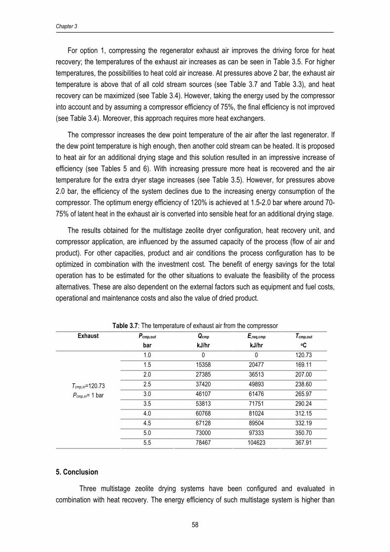
Chapter 3
58
For option 1, compressing the regenerator exhaust air improves the driving force for heat
recovery; the temperatures of the exhaust air increases as can be seen in Table 3.5. For higher
temperatures, the possibilities to heat cold air increase. At pressures above 2 bar, the exhaust air
temperature is above that of all cold stream sources (see Table 3.7 and Table 3.3), and heat
recovery can be maximized (see Table 3.4). However, taking the energy used by the compressor
into account and by assuming a compressor efficiency of 75%, the final efficiency is not improved
(see Table 3.4). Moreover, this approach requires more heat exchangers.
The compressor increases the dew point temperature of the air after the last regenerator. If
the dew point temperature is high enough, then another cold stream can be heated. It is proposed
to heat air for an additional drying stage and this solution resulted in an impressive increase of
efficiency (see Tables 5 and 6). With increasing pressure more heat is recovered and the air
temperature for the extra dryer stage increases (see Table 3.5). However, for pressures above
2.0 bar, the efficiency of the system declines due to the increasing energy consumption of the
compressor. The optimum energy efficiency of 120% is achieved at 1.5-2.0 bar where around 70-
75% of latent heat in the exhaust air is converted into sensible heat for an additional drying stage.
The results obtained for the multistage zeolite dryer configuration, heat recovery unit, and
compressor application, are influenced by the assumed capacity of the process (flow of air and
product). For other capacities, product and air conditions the process configuration has to be
optimized in combination with the investment cost. The benefit of energy savings for the total
operation has to be estimated for the other situations to evaluate the feasibility of the process
alternatives. These are also dependent on the external factors such as equipment and fuel costs,
operational and maintenance costs and also the value of dried product.
Table 3.7: The temperature of exhaust air from the compressor
Exhaust
Pcmp,out
bar
Qcmp
kJ/hr
E,req,cmp
kJ/hr
Tcmp,out
oC
1.0 0 0 120.73
1.5 15358 20477 169.11
2.0 27385 36513 207.00
2.5 37420 49893 238.60
3.0 46107 61476 265.97
3.5 53813 71751 290.24
4.0 60768 81024 312.15
4.5 67128 89504 332.19
5.0 73000 97333 350.70
Tcmp,in=120.73
Pcmp,in= 1 bar
5.5 78467 104623 367.91
5. Conclusion
Three multistage zeolite drying systems have been configured and evaluated in
combination with heat recovery. The energy efficiency of such multistage system is higher than

Multistage Zeolite Dying for Efficient Drying
59
that of conventional drying systems and single stage zeolite drying systems. The efficiency
increases with the number of stages. Generally, the multistage systems are most effective for 2-3
stages; above this number the energy efficiency improvement is marginal and probably not
sufficient to justify the increase of system complexity. The counter-current dryer is the most
efficient and achieves an energy efficiency of 88% for a 3-stage system.
Heat recovery is enhanced with the introduction of a compressor which increases the
temperature of the zeolite regenerator exhaust air. As a result the possibilities to recover sensible
and latent heat improves. Both aspects enhance the amount of recovered energy. However, it
appears that the energy required for the compressor energy cancels the benefits.
The other way is to use the compressed air to heat up other cold streams. In this work air
for an additional drying stage is heated up. It improves the energy efficiency up to 120%. In this
case, the latent heat in the exhaust gas is used by vapor condensation. Although, increasing the
exhaust air temperature and pressure gives more potential to recover latent heat, there is an
tendency for an optimum efficiency at 1.5-2.0 bar.
In many industries the high energy consumption for drying process is regarded as a
serious problem. In conventional drying systems with inlet air temperatures between 60 and 90°C
the maximal efficiency is around 60-65%. The multistage drying system realizes an efficiency
level of 110-120% for the same conditions. In other words the energy consumption is halved,
which is regarded as a significant step ahead in saving energy.
Acknowledgement
This work is supported by the staff training program (TPSDP) of the Chemical
Engineering Department of the Diponegoro University, Semarang Indonesia.
References
1. Djaeni, M.; Bartels, P.; Sanders, J.; Straten, G. van; Boxtel, A.J.B. van. Process integration
for food drying with air dehumidified by zeolites. Drying Technology 2007, 25 (1), 225-239
2. Jenkins, S.A.; Waszkiewicz, S.; Quarini, G.L; Tierney, M.J. Drying saturated zeolite pellets
to assess fluidised bed performance. Applied Thermal Engineering 2002, 22 (7), 861-871
3. Spets, J.P. New multi-stage drying system. Proceedings of the 1st Nordic Drying
Conference; Trondheim, Norway, June 21-29, 2001; paper number 13
4. Holmberg, H.; Ahtila, P. Comparison of drying costs in biofuel drying between multi-stage
and single-stage drying. Journal of Biomass and Bioenergy 2004, 26(6), 515-530
5. Spets, J.P.; Ahtila, P. Preliminary economical examinations for a new multistage biofuel
drying system integrated in industrial CHP-power plant. Proceedings of the 1st Nordic
Drying Conference; Trondheim, Norway, June 21-29, 2001; paper number 14
6. Holmberg, H.; Ahtila, P. Evaluation of energy efficiency in biofuel drying by means of
energy and exergy analyses. Applied Thermal Engineering 2005, 25, 3115-3128

Chapter 3
60
7. Arabhosseini, M.A.A. Quality, Energy Requirement, and Costs of Drying Tarragon
(Artemisia dracunculus L.). Doctoral Thesis; Wageningen University: The Netherlands,
2005
8. Linnhoff, B. User Guide on Process Integration for the Efficient Use of Energy; The
Institution of Chemical Engineers: Rugby, UK, 1994
9. Kemp, I.C. Reducing dryer energy use by process integration and pinch analysis. Drying
Technology 2005, 23, 2089-2104
10. Krokida, M.K.; Bisharat, G.I. Heat recovery from dryer exhaust air. Drying Technology
2004, 22 (7), 1661-1674
11. Perry, R.H.; Green D.W. Perry’s Chemical Engineers’ Handbook, 7th Intl. ed.; McGraw-Hill:
Singapore, 1998
12. Anonymous. Matter and its atomic structure. The University of Western
Ontario:Canada,2003. http://www.astro.uwo.ca/~jlandstr/planets/webfigs/matter/slide5.html
(accessed April 14, 2006)
Appendix 3.1
Figure A1-1: Counter-current zeolite dryer
Exhaust 120-130oC
Ambient air to Regenerator 25oC, Ya,,in =0.01
Dryer 1
Adsorber 1
Regenerator 1
Heater 1
Pre-heater
Cooler 1
Air Regenerator 110-120oC
Air dryer
Zeolite 50oC Xz=0.20
Air dryer 25oC Ya,in=0.010
Product 70-80oC Xp=0.11
Stage 1
Air Regenerator 160-170oC
Dryer n
Adsorber n
Regenerator n
Heater n
Cooler n
Air Regenerator
Heat Recovery Unit
Exhaust
Stage n
Air dryer 35-40oC
Air dryer 75-80oC
Product 25oC Xp=2.33
Zeolite 160-170oC Xz=0.0
Product
Air dryer
Stage 2
Dryer 2
Adsorber 2
Regenerator 2
Heater 2
Cooler 2
Air dryer 35-40oC Ya=0.014
Air dryer 70-75oC Ya,=0.0014
Zeolite 70-75oC Xz=0.20
Zeolite 140-150oC Xz=0.0
Zeolite 75-80oC Xz=0.20 Zeolite
120-130oC Xz=0.0
Air dryer 35-40oC
300oC

Multistage Zeolite Dying for Efficient Drying
61
Figure A1-2: Co-current zeolite dryer
Figure A1-3: Cross-current zeolite dryer
Ambient air to Regenerator 25oC, Ya=0.01
Exhaust
Exhaust 120-130oC
Dryer 1
Adsorber 1
Regenerator 1
Heater 1
Pre-heater
Cooler 1
Air dryer
Stage 1
Air dryer
Product 35-40oC Xp=0.11 Product
Dryer n
Adsorber n
Regenerator n
Heater n
Cooler n
Air Regenerator
Heat Recovery Unit
Stage n
Product 25oC Xp=2.33
Air dryer 25oC Ya,in=0.010
Air Regenerator 110-120oC
Zeolite 160-170oC Xz=0.0
Zeolite 50oC Xz=0.20
Stage 2
Dryer 2
Adsorber 2
Regenerator 2
Heater 2
Cooler 2
Air dryer 70-75oC Ya=0.0014
Air dryer 35-40oC Ya=0.014
Air Regenerator 160-170oC
Zeolite 70-75oC Xz=0.20 Zeolite
140-150oC Xz=0.0
Zeolite 75-80oC Xz=0.20
Zeolite 120-130oC Xz=0.0
Air dryer 75-80oC
Air dryer 30-35oC
Air dryer 35-40oC
300oC 300oC 300oC
Dryer 1
Adsorber 1
Regenerator 1
Heater 1
Pre-heater
Cooler 1
Air Regenerator 110-120oC
Air dryer
Zeolite 50oC Xz=0.2
Air dryer 25oC Ya,in=0.010
Stage 1
Air dryer
Stage 2
Dryer 2
Adsorber 2
Regenerator 2
Heater 2
Product 35-40oC Xp=0.11
Air dryer 35-40oC Ya=0.014
Air Regenerator 160-170oC
Dryer-n
Adsorber n
Regenerator n
Heater n
Air dryer 75-80oC
Zeolite 75-80oC Xz=0.2
Air Regenerator
Heat Recovery Unit
Ambient air to Regenerator 25oC, Ya=0.01
Exhaust
Stage n
Exhaust 120-130oC
Product Xp=0.11
Zeolite 160-170oC Xz=0.0
Zeolite 70-75oC Xz=0.2 Zeolite
150-160oC Xz=0.0
Zeolite 120-130oC Xz=0.0
Air dryer 35-40oC
Air dryer 70-75oC Ya=0.0014
Air dryer 35-40oC
Product 25oC, Xp=2.33
Product Xp=0.11
Product 25oC, Xp=2.33
Product 25oC, Xp=2.33
300oC 300oC 300oC
Cooler 2
Cooler n

Chapter 3
62
Appendix 3.2
For the calculations both drying systems are split into subsystems. Steady-state models
for the subsystems based on the conservation of mass and enthalpy are used. Assumptions for
the calculations are:
� adiabatic processes for the subunits,
� constant physical properties (density, specific heat),
� pressure drop is excluded from the calculations,
� operational pressure 1 bar,
� well mixed subsystems,
� in all cases the exhaust air of the dryer has a relative humidity of 40%,
� in the adsorption unit 90% of moisture content in the air is removed,
� at the exit of each unit air and solid material have the same temperature
� the enthalpy reference is 0°C
Values used for calculations are given in Table A2-1, Appendix 3.2.
a. Adsorption Unit (see Figure A2-1)
Figure A2-1: Adsorber input-output streams
Assumptions
- Balances are based on dry air and dry zeolite flows
- Dry air flow in equals dry air flow out: aout,ain,a FFF ==
- Dry zeolite flow in equals dry zeolite flow out : zout,zin,z FFF ==
The water mass balance is:
out,zzout,aain,zzin,aa XFYFXFYF +=+ (A2-1)
The enthalpy balance for the adsorber is:
in,ain,aa T,Y,F
in,zin,zz T,X,F
Adsorber
out,zout,zz T,X,F
out,aout,aa T,Y,F Air Zeolite

Multistage Zeolite Dying for Efficient Drying
63
adsout,zout,ain,zin,a HHHHH ++=+ (A2-2)
)YHT)cYc((FH in,avin,av,pin,aa,pain,a ∆++= (A2-3)
in,zw,pin,zz,pzin,z T)cXc(FH += (A2-4)
)YHT)cYc((FH out,avout,av,pout,aa,paout,a ∆++= (A2-5)
out,zw,pout,zz,pzout,z T)cXc(FH += (A2-6)
zin,zout,zadsads F)XX(HH −∆= (A2-7)
b. Regenerator Unit
The mass and enthalpy balances for regenerator are almost equal to that of the adsorber.
However, here energy is required to release water from the zeolite.
out,zout,adesin,zin,a HHHHH +=−+ (A2-8)
adsdes HH −= (A2-9)
Those balances are used to calculate the temperature and air humidity of the outlet
streams. Analog equations as given for the adsorber are used.
c. Heater and Pre-Heater (see Figure A2-2)
Figure A2-2: Heater input-output streams
The enthalpy balance for the heater is given as balance form:
out,ahein,a HQH =+ (A2-10)
The inlet and outlet air enthalpy follow from the stream conditions. The required heat for the
heater is calculated.
out,heout,aa T,Y,F
out,heout,aa T,Y,F Heater
Qhe

Chapter 3
64
d. Dryer (see Figure A2-3)
Figure A2-3: Dryer input-output streams
Assumptions
- Balances are based on dry air and product flows
- Dry air flow in equals dry air flow out: aout,ain,a FFF ==
- Dry product flow in equals dry product flow out : pout,pin,p FFF ==
In the dryer mass and energy exchange take place. The water balance using dry basis air and
product flow are as follows:
out,pout,pout,aain,ppin,aa XFYFXFYF +=+ (A2-11)
)T(YRHY out,dsatoutout,a = (A2-12)
where satY represents the water vapor saturation line in the psychometric chart and
depends on outlet dryer temperature ( ),outdT , which follows from the enthalpy balance of dryer.
The balances are:
evapout,pout,ain,pin,a HHHHH ++=+ (A2-13)
out,pw,pout,pp,ppout,p T)cXc(FH += (A2-14)
pout,pin,pvevap F)XX(HH −∆= (A2-15)
in,pw,pin,pp,ppin,p T)cXc(FH += (A2-16)
Physical constants and operational conditions are given Appendix 3.2. The product
moisture content leaving the dryer ( outpX , ) is set to 0.111 kg water/kg dry product, and outlet
temperature of product and air equals ( outdoutaoutp TTT ,,, == ). The flow of dry product and outlet
dryer temperature are result of the calculations. The effect of product/air temperature on product
moisture at given relative humidity proved to be minimal and is neglected.
in,ain,aa T,Y,F Dryer
in,pin,pp T,X,F
Air Product
out,pout,pp T,X,F
out,aout,aa T,Y,F
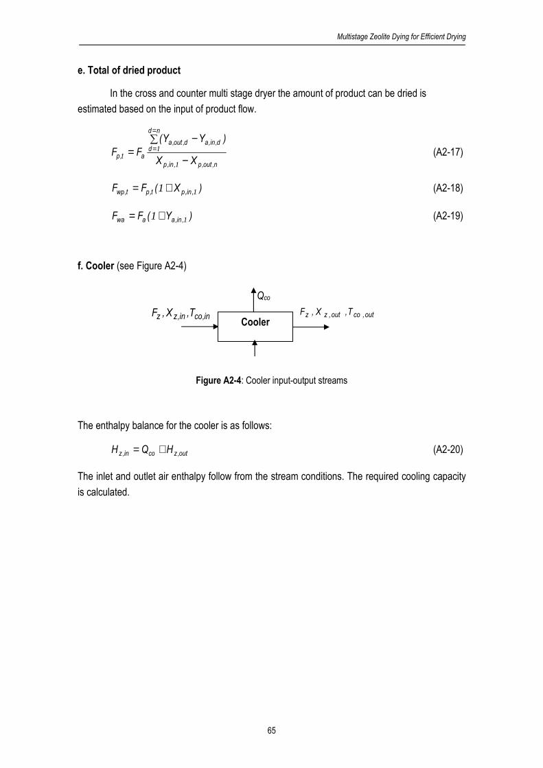
Multistage Zeolite Dying for Efficient Drying
65
e. Total of dried product
In the cross and counter multi stage dryer the amount of product can be dried is
estimated based on the input of product flow.
n,out,p,in,p
nd
dd,in,ad,out,a
at,pXX
)YY(
FF−
∑ −=
=
=
1
1 (A2-17)
)X(FF ,in,pt,pt,wp 11 += (A2-18)
)Y(FF ,in,aawa 11 += (A2-19)
f. Cooler (see Figure A2-4)
Figure A2-4: Cooler input-output streams
The enthalpy balance for the cooler is as follows:
out,zcoin,z HQH += (A2-20)
The inlet and outlet air enthalpy follow from the stream conditions. The required cooling capacity
is calculated.
in,coin,zz T,X,F out,coout,zz T,X,F Cooler
Qco
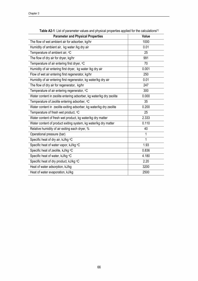
Chapter 3
66
Table A2-1: List of parameter values and physical properties applied for the calculations[1]
Parameter and Physical Properties Value
The flow of wet ambient air for adsorber, kg/hr 1000
Humidity of ambient air, kg water /kg dry air 0.01
Temperature of ambient air, oC 25
The flow of dry air for dryer, kg/hr 991
Temperature of air entering first dryer, oC 70
Humidity of air entering first dryer, kg water /kg dry air 0.001
Flow of wet air entering first regenerator, kg/hr 250
Humidity of air entering first regenerator, kg water/kg dry air 0.01
The flow of dry air for regenerator, kg/hr 247
Temperature of air entering regenerator, oC 300
Water content in zeolite entering adsorber, kg water/kg dry zeolite 0.000
Temperature of zeolite entering adsorber, oC 35
Water content in zeolite exiting adsorber, kg water/kg dry zeolite 0.200
Temperature of fresh wet product, oC 25
Water content of fresh wet product, kg water/kg dry matter 2.333
Water content of product exiting system, kg water/kg dry matter 0.110
Relative humidity of air exiting each dryer, % 40
Operational pressure (bar) 1
Specific heat of dry air, kJ/kg oC 1
Specific heat of water vapor, kJ/kg oC 1.93
Specific heat of zeolite, kJ/kg oC 0.836
Specific heat of water, kJ/kg oC 4.180
Specific heat of dry product, kJ/kg oC 2.20
Heat of water adsorption, kJ/kg 3200
Heat of water evaporation, kJ/kg 2500
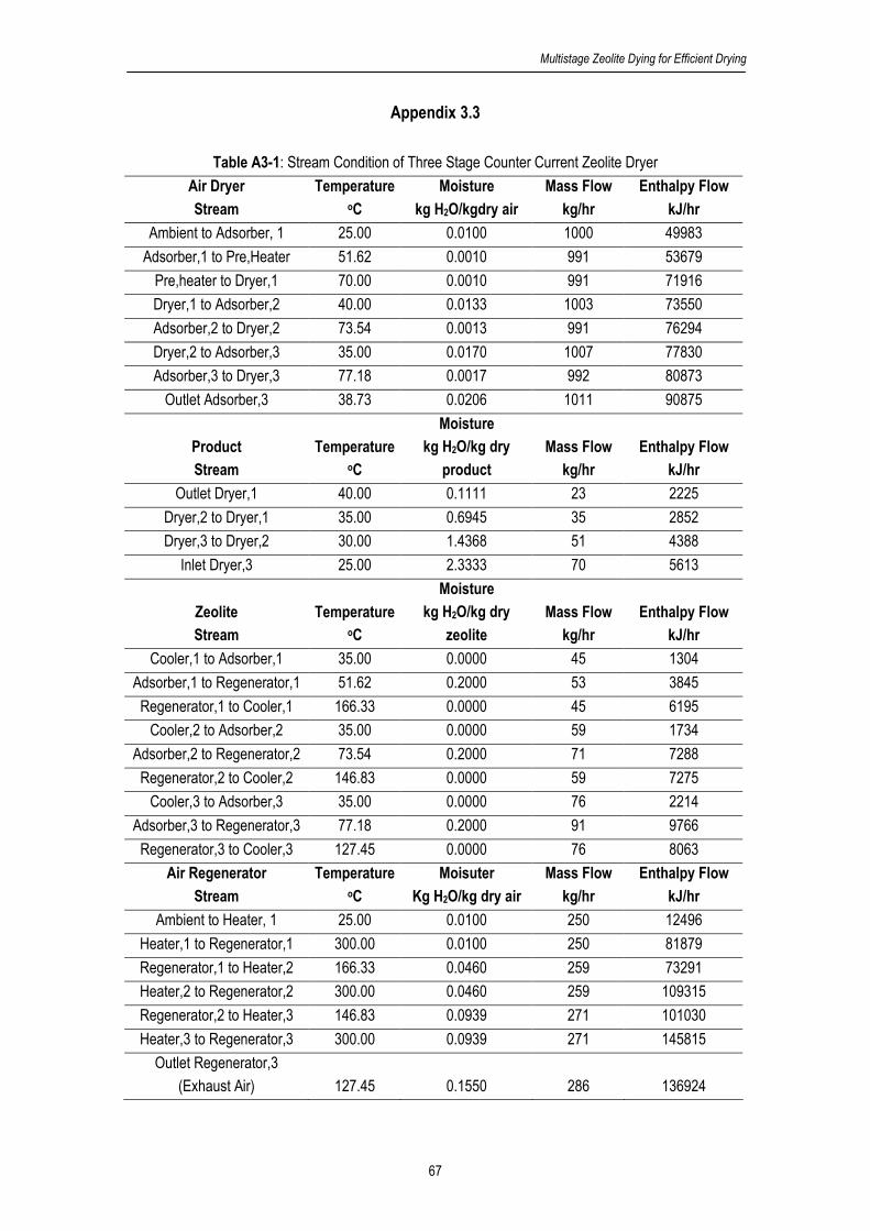
Multistage Zeolite Dying for Efficient Drying
67
Appendix 3.3
Table A3-1: Stream Condition of Three Stage Counter Current Zeolite Dryer
Air Dryer
Stream
Temperature oC
Moisture
kg H2O/kgdry air
Mass Flow
kg/hr
Enthalpy Flow
kJ/hr
Ambient to Adsorber, 1 25.00 0.0100 1000 49983
Adsorber,1 to Pre,Heater 51.62 0.0010 991 53679
Pre,heater to Dryer,1 70.00 0.0010 991 71916
Dryer,1 to Adsorber,2 40.00 0.0133 1003 73550
Adsorber,2 to Dryer,2 73.54 0.0013 991 76294
Dryer,2 to Adsorber,3 35.00 0.0170 1007 77830
Adsorber,3 to Dryer,3 77.18 0.0017 992 80873
Outlet Adsorber,3 38.73 0.0206 1011 90875
Product
Stream
Temperature oC
Moisture
kg H2O/kg dry
product
Mass Flow
kg/hr
Enthalpy Flow
kJ/hr
Outlet Dryer,1 40.00 0.1111 23 2225
Dryer,2 to Dryer,1 35.00 0.6945 35 2852
Dryer,3 to Dryer,2 30.00 1.4368 51 4388
Inlet Dryer,3 25.00 2.3333 70 5613
Zeolite
Stream
Temperature oC
Moisture
kg H2O/kg dry
zeolite
Mass Flow
kg/hr
Enthalpy Flow
kJ/hr
Cooler,1 to Adsorber,1 35.00 0.0000 45 1304
Adsorber,1 to Regenerator,1 51.62 0.2000 53 3845
Regenerator,1 to Cooler,1 166.33 0.0000 45 6195
Cooler,2 to Adsorber,2 35.00 0.0000 59 1734
Adsorber,2 to Regenerator,2 73.54 0.2000 71 7288
Regenerator,2 to Cooler,2 146.83 0.0000 59 7275
Cooler,3 to Adsorber,3 35.00 0.0000 76 2214
Adsorber,3 to Regenerator,3 77.18 0.2000 91 9766
Regenerator,3 to Cooler,3 127.45 0.0000 76 8063
Air Regenerator
Stream
Temperature oC
Moisuter
Kg H2O/kg dry air
Mass Flow
kg/hr
Enthalpy Flow
kJ/hr
Ambient to Heater, 1 25.00 0.0100 250 12496
Heater,1 to Regenerator,1 300.00 0.0100 250 81879
Regenerator,1 to Heater,2 166.33 0.0460 259 73291
Heater,2 to Regenerator,2 300.00 0.0460 259 109315
Regenerator,2 to Heater,3 146.83 0.0939 271 101030
Heater,3 to Regenerator,3 300.00 0.0939 271 145815
Outlet Regenerator,3
(Exhaust Air) 127.45 0.1550 286 136924

Chapter 3
68
Chapter 4
Energy Efficiency of
Multistage Adsorption Drying for
Low Temperature Drying
Accepted for Drying Technology, 2008;
published in Proceeding of ADC 2007, Hongkong
Chapter 4
70
Abstract
This work discusses the evaluation of multistage adsorption dryers with air dehumidification by
zeolite and alumina pillared clay. In a multistage dryer product is dried in succeeding stages while
air leaving a stage is fed to the next stage after dehumidification by an adsorbent. Energy
efficiency of the drying system is evaluated for low temperature drying (10-50°C) and compared
with conventional condenser drying. Results showed that the efficiency of the multistage
adsorption dryers increase with the number of stages. For low drying temperatures zeolite is most
favourable; for drying temperatures 40-50°C alumina pillared clay needs less cooling and
deserves preference.
Keywords: multistage drying, adsorption, zeolite, alumina pillared clay, energy efficiency,
condensation drying
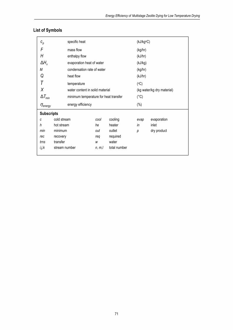
Energy Efficiency of Multistage Zeolite Dying for Low Temperature Drying
71
List of Symbols
pc specific heat (kJ/kgoC)
F mass flow (kg/hr)
H enthalpy flow (kJ/hr)
vH∆ evaporation heat of water (kJ/kg)
M condensation rate of water (kg/hr)
Q heat flow (kJ/hr)
T temperature (oC)
X water content in solid material (kg water/kg dry material)
minT∆ minimum temperature for heat transfer (°C)
energyη energy efficiency (%)
Subscripts c cold stream cool cooling evap evaporation
h hot stream he heater in inlet
min minimum out outlet p dry product
rec recovery req required
trns transfer w water
i,j,k stream number n, m,l total number

Chapter 4
72
1. Background
Low temperature drying in the temperature range 10-50°C is favorable to limit product
deterioration such as browning, shrinkage and structure deformation, the loss of valuable organic
content is inhibited and product quality is retained [1] . However, the processes are expensive,
need long operational time, and are complex if applied under vacuum and/or refrigerating
conditions. Moreover, energy efficiency is below that for high temperature drying.
In conventional low temperature dryers water is removed from the air by condensation.
The air is cooled air below the dew point temperature and subsequently heated up to the drying
temperature. The dehumidified air is then used for drying, but the total energy efficiency is mostly
below 50%. Therefore, it is a challenge to improve the energy efficiency and also to speed up the
drying rate for low temperature drying. For example, Sosle et al [2] applied a heat pump for air
dehumidification to enhance the performance. However, compared to the conventional dryer, the
result did not affect energy efficiency and drying time significantly. Xu et al [3] proposed a
combination of a vacuum freeze dryer and a convective air dryer in two successive stages. This
system could be a potential option, since the product quality is maintained. The result with a
energy efficiency of 50-60% is only meaningful as an alternative for vacuum freeze dryers.
Air dehumidification by adsorbents is another option to enhance the drying efficiency. [1,4,5,6] With this method, the air is dehumidified by adsorbing water while the air temperature
increases at the same time due to the release of the adsorption heat. As a result, the dryer inlet
air can contain more sensible heat for drying which improves the total energy efficiency.
Moreover, with a lower humidity, the driving force of drying is improved and as a result the drying
time is reduced. Simulation studies of single and multistage zeolite drying for the temperature
range 50-90°C showed that a energy efficiency of 75-90% can be achieved, and in special
configurations for heat recovery the efficiency may go up to 120%. [6,7]
For low temperature drying in the range 10-50°C, the possibilities for heat recovery differ
from medium temperature drying in multistage zeolite dryers. [8] Another aspect is that in medium
temperature drying the dehumidified air needs additional heating, while for low temperature
drying it can be necessary to cool the air after dehumidification. Both aspects result in a lower
energy efficiency of multistage adsorption dryers.
This paper evaluates the energy efficiency of low temperature adsorption dryers using
zeolite and alumina pillared clay for air dehumidification compared to condensation dryers by
taking into account the energy for heating and cooling. The effects of the number of stages, dryer
inlet temperature and ambient air on the energy efficiency of the dryers are discussed.
2.Methodology
The energy efficiency is evaluated for dryers operating with inlet temperatures in the
range10-50°C, using Dutch ambient air conditions throughout the seasons (see Table 4.1). Air is
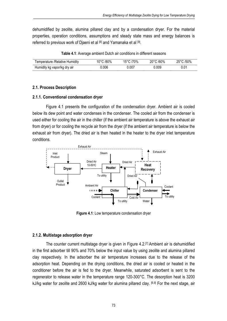
Energy Efficiency of Multistage Zeolite Dying for Low Temperature Drying
73
dehumidified by zeolite, alumina pillared clay and by a condensation dryer. For the material
properties, operation conditions, assumptions and steady state mass and energy balances is
referred to previous work of Djaeni et al [6] and Yamanaka et al [9].
Table 4.1: Average ambient Dutch air conditions in different seasons
Temperature /Relative Humidity 10°C /80% 15°C /70% 20°C /60% 25°C /50%
Humidity kg vapor/kg dry air 0.006 0.007 0.009 0.01
2.1. Process Description
2.1.1. Conventional condensation dryer
Figure 4.1 presents the configuration of the condensation dryer. Ambient air is cooled
below its dew point and water condenses in the condenser. The cooled air from the condenser is
used either for cooling the air in the chiller (if the ambient air temperature is above the exhaust air
from dryer) or for cooling the recycle air from the dryer (if the ambient air temperature is below the
exhaust air from dryer). The dried air is then heated in the heater to the dryer inlet temperature
conditions.
Figure 4.1: Low temperature condensation dryer
2.1.2. Multistage adsorption dryer
The counter current multistage dryer is given in Figure 4.2.[7] Ambient air is dehumidified
in the first adsorber till 90% and 70% below the input value by using zeolite and alumina pillared
clay respectively. In the adsorber the air temperature increases due to the release of the
adsorption heat. Depending on the drying conditions, the dried air is cooled or heated in the
conditioner before the air is fed to the dryer. Meanwhile, saturated adsorbent is sent to the
regenerator to release water in the temperature range 120-300°C. The desorption heat is 3200
kJ/kg water for zeolite and 2600 kJ/kg water for alumina pillared clay. [6,9] For the next stage, air
Heater
Inlet Product
Outlet Product
Exhaust Air
Steam
To utility
Heat Recovery
Chiller Condenser
Ambient Air
Cold Air
Dried Air
Coolant
Exhaust Air
To utility
Dried Air 10-50oC
Dried Air
Water
Dryer
Coolant To utility
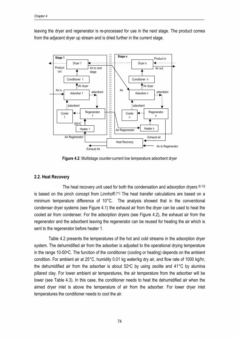
Chapter 4
74
leaving the dryer and regenerator is re-processed for use in the next stage. The product comes
from the adjacent dryer up stream and is dried further in the current stage.
Figure 4.2: Multistage counter-current low temperature adsorbent dryer
2.2. Heat Recovery
The heat recovery unit used for both the condensation and adsorption dryers [6,10]
is based on the pinch concept from Linnhoff.[11] The heat transfer calculations are based on a
minimum temperature difference of 10°C. The analysis showed that in the conventional
condenser dryer systems (see Figure 4.1) the exhaust air from the dryer can be used to heat the
cooled air from condenser. For the adsorption dryers (see Figure 4.2), the exhaust air from the
regenerator and the adsorbent leaving the regenerator can be reused for heating the air which is
sent to the regenerator before heater 1.
Table 4.2 presents the temperatures of the hot and cold streams in the adsorption dryer
system. The dehumidified air from the adsorber is adjusted to the operational drying temperature
in the range 10-50oC. The function of the conditioner (cooling or heating) depends on the ambient
condition. For ambient air at 25°C, humidity 0.01 kg water/kg dry air, and flow rate of 1000 kg/hr,
the dehumidified air from the adsorber is about 52oC by using zeolite and 41°C by alumina
pillared clay. For lower ambient air temperatures, the air temperature from the adsorber will be
lower (see Table 4.3). In this case, the conditioner needs to heat the dehumidified air when the
aimed dryer inlet is above the temperature of air from the adsorber. For lower dryer inlet
temperatures the conditioner needs to cool the air.
Air to Regenerator Heat Recovery
Exhaust Air
Dryer 1
Adsorber 1
Regenerator 1
Heater 1
Conditioner 1
Cooler 1
adsorbent
Air Regenerator
Air dryer
adsorbent
Air in
Product out
Stage 1
Air to next stage
300oC
Exhaust air
Dryer n
Adsorber n
Regenerator n
Heater n
Conditioner n
Cooler n
adsorbent
Air dryer
adsorbent
Air
Product in Stage n
Air out
Air Regenerator

Energy Efficiency of Multistage Zeolite Dying for Low Temperature Drying
75
Table 4.2 shows that the cold streams 2,3,..,n cannot be heated up by the hot streams,
since they are at same level. For heat recovery only the zeolite flow and the exhaust air flow from
the regenerators (hot 1 and 2) can be combined with the air fed to the regenerator 1 (cold 1). Air
from the adsorber can be used as cold 2 when the temperature is below the dryer inlet
temperature, or it can be used as a hot stream (hot 3 in Figure 4.3) when its temperature is above
the dryer inlet temperature. Figure 4.3 presents the possible configuration for heat recovery.
Table 4.2: Overview of hot and cold streams Type Stream T (source) oC T (target) oC Enthalpy flow
kJ/hr
Hot Stream Hot 1 Zeolite from regenerator 1,2,.,n 120-160 35 6000-13200*
Hot 2 Exhaust air from regenerator-n 120-160 35 75000-125000*
Cold Stream Cold 1 Air entering regenerator- 1 25 300 12500 Cold 2 Air entering regenerator- 2 120-160 200 73300* Cold n Air entering regenerator -n 120-160 200 75000*
* the values for enthalpy flow depend on the stage number
Table 4.3: Temperature of air exiting first adsober in different air ambient
Ambient temperature (oC)
Humidity kg water/kg dry air
Ambient Relative Humidity
%
Temperature of air from the first adsorber (oC) zeolite/pillared clay
10 0.006 80 27/22
15 0.007 70 34/28
20 0.009 60 44/36
25 0.01 50 52/41
The heat recovery system is presented in Figure 4.3. The amount of heat recovery is
calculated by summarizing the heat transferred in each heat exchanger and concerns sensible
and latent heat.
For c,pFc ≥ h,pFc , the total heat recovered is
∑∑= =
∆+∆+−=n
1i
m
1j
vji,wmin
ji,c
ji,h
ji,h,p
ji,htotal,trns HM))TT(T(cFQ (1)
If c,pFc ≤ h,pFc , the total heat recovery is:
∑∑= =
∆+−=n
1i
m
1j
minji,c
ji,h
ji,c,p
ji,ctotal,trns ))TT(T(cFQ (2)
total,trnsrec QQ = (3)

Chapter 4
76
Figure 4.3: Heat recovery unit for improving the total energy efficiency
2.3. Performance evaluation
The performance evaluation uses the overall energy efficiency as main indicator. The
energy efficiency is estimated by taking into account energy for heating and cooling. Energy for
heating is derived from heat required to the system after recovery. While, the energy for cooling is
based on the energy to cool the dehumidified air to reach dryer condition. The energy efficiency
can be as follows:
%100QQ
Q
reqcool
evapenergy +
=η (4)
with evapQ as the total heat required for evaporating water from the product, and is defined by:
vout,pin,php,pevap ∆H)XX(cFQ −= (5)
reqQ is the total of net heat used by the dryer system an follows from the total heat introduced in
all heaters minus the total recovered heat:
rec
ni
0i
ihereq Q)Q(Q −=∑=
=
(6)
At the conventional condenser dryer, the air is cooled to bring the air temperature below
its dew point and to condense the moisture in the air (see Figure 4.1). Whereas, for adsorption
cold 1
cold Utility
cold 2
hot Utility
= Heat Exchanger
Zeolite from Regenerator n
Zeolite from Regenerator 1
Zeolite from Regenerator 2
1,1 1,2
2,1 2,2
n,1 n,2
hot 3
hot 2
hot 1
Air from adsober
If temperature > dryer temperature
If temperature < dryer temperature
Target temperature
Exhaust air from last regenerator
Energy Efficiency of Multistage Zeolite Dying for Low Temperature Drying
77
dryer, cooling can be required after the adsorber to bring the air temperature at the dryer
condition (see Figure 4.2). In general, the energy for cooling can be expressed as follows:
∑=
+−=n
1i
viw,targeth,inh,p,hhcool ∆HM)T(TcFQ (7)
with coolQ as the energy for cooling in each condenser, cooler and conditioner, kJ/hr (for
adsorption dryer, 0=∆ vi,w HM )
3. Results and discussion
3.1. Effect of temperature and number of stages on efficiency
Figure 4.4 presents the energy efficiency of a single-stage (number of stages is 1) and a
series of multistage zeolite dryers which operate at different dryer inlet temperatures and use
ambient air at 25oC and with absolute air humidity of 0.01 kg water/kg dry air (i.e. 50% relative
humidity).
The energy efficiency of the adsorption dryer increases with increasing operational
temperature and stage number. For dryer inlet temperatures at 30°C and below, the number of
stages has a significant effect on the energy efficiency which indicate that heat recovery of the
exhaust air leaving the regenerators (hot 2) is significant. For 40°C, above three stages the
improvement is marginal and in such application a three stage dryer seems economically most
promising.
In these systems only hot streams with high temperatures are used for heat recovery.
The heat in the air leaving the adsorbers is not recovered since all cold streams need higher
temperature levels (see Table 4.1 and 2). Thus the adsorption heat obtained in the adsorbers is
not used.
Figure 4.4 shows also that the energy efficiency goes down for the lower operational
temperatures. This outcome is result of the lower capacity of the dehumidified air for taking up
water from the product at low temperatures. Moreover, for low temperature drying (<30oC) the
conditioner requires more energy for cooling which cannot be recovered (see Table A.1,
Appendix 4).
Compared with zeolite, alumina pillared clay has a lower capacity to adsorb water from
air, and alumina pillared clay cannot be applied as adsorbent for temperatures below 20°C (see
also Table A.1, Appendix 4). The lower capacity for adsorption of alumina pillared clay at low
temperatures results in a lower degree of dehumidification and thus a lower driving force for
drying. Hence, the energy efficiency of alumina pillared clay for low temperatures is below that of
the dryer using zeolite; while at 30°C the performance is equal. At 40°C, the energy efficiency of
alumina pillared clay system is higher than that of zeolite, since the zeolite system needs more

Chapter 4
78
energy to cool the released adsorption heat. As a consequence, by choosing an adsorbent with a
lower adsorption heat, the energy for cooling can be minimized; even up to zero (see Table A.1,
Appendix 4).
0.00
10.00
20.00
30.00
40.00
50.00
60.00
1 2 3 4
Number of stage
Ene
rgy
effic
ienc
y, %
Zeo 20
Zeo 30
Zeo 40
Clay 20
Clay 30
Clay 40
Figure 4.4: Energy efficiency for the multistage dryers as a function of the number of stages and drying
temperature. Tambient=25°C, Yambient=0.010 kg water/kg dry air, and Fair= 1000 kg/hr. Zeo refers
to zeolite, and Clay refers to alumina pillared clay
3.2 Varying ambient conditions
The performance of the adsorber dryers is evaluated for different ambient temperatures
and compared to dryers with dehumidification by condensation. The considered multistage
adsorption dryer is a three stage counter current system.
Figure 4.5 presents the energy efficiency of the condensation dryer and the three stage
adsorbent dryers using zeolite and alumina pillared clay respectively. The results show that for
the lower ambient temperatures, the energy efficiency of the adsorbent dryers surmounts that of
the condensation dryer. This outcome is sum of the following aspects:
1. at one hand, for low ambient temperatures, more energy is required to bring the air
temperature from the low values to the drying temperature, and
2. also at lower ambient temperatures a lower amount of water is removed from the air, thus
less heat is released in the adsorber which has to be compensated by additional heating,
3. but, the required extra heat is gained from the heat recovery units which makes the system
more efficient, especially for ambient air temperature below 20°C, and

Energy Efficiency of Multistage Zeolite Dying for Low Temperature Drying
79
4. because of the lower amount of water adsorbed in the adsorbers, less water has to be
removed from the adsorbent in the regenerator; therefore the regenerator requires less
energy, and
5. finally, the energy for cooling decreases, since the temperature of the dehumidified air is
close to the dryer inlet temperature.
All these aspects make the total balance profitable for the adsorbent systems.
For dryer inlet temperatures above 40°C, the energy efficiency of the conventional
condensation dryers increase for decreasing ambient temperature. The ambient air is not very
suitable as hot stream. Thus, the exhaust air from the dryer can be used as hot stream in which
increases the heat recovery. In addition, decreasing ambient air temperature also causes the
energy for cooling being lower due to less water content to be condensed in ambient air (see
Table A.2, Appendix 4).
0.00
10.00
20.00
30.00
40.00
50.00
60.00
70.00
80.00
5 10 15 20 25 30
Ambient temperature, °C
Ene
rgy
effic
ienc
y, % Zeo 20
Zeo 40
Clay 20
Clay 40
Conv. 20
Conv. 40
Figure 4.5: The effect of ambient temperature and dryer inlet temperature on the energy efficiency. Zeo:
zeolite dryer, Conv: conventional condenser dryer, Clay: alumina pillared clay
4. Conclusion
The energy efficiency of multistage adsorption dryers is significantly better than that of
conventional condenser dryers. The ambient air used for drying and the temperature of air fed to
the dryer are important parameters for the energy efficiency.
For drying inlet temperatures below 30°C the zeolite dryer is beneficial since the air fed
to the dryer has a low water content resulting in a high driving force for drying. For 40-50°C, the
multistage dryer with alumina pillared clay needs no cooling while the zeolite system has to be
cooled for these conditions. As a result, for these drying temperatures the alumina pillared clay is
advantageous compared to zeolite.

Chapter 4
80
Acknowledgement
This work is funded by the staff training program (TPSDP) of the Chemical Engineering
department of the Diponegoro University, Semarang Indonesia, and NEOT01005 project, Energy
Research Program EOS of the Dutch Ministry of Economics.
References
1. Ratti C. Hot air and freeze-drying of high-value foods: a review. Journal of Food
Engineering 2001, 49, 311-319
2. Sosle, V.; Raghavan, G.S.V.; Kittler, R. Low-temperature drying using a versatile heat
pump dehumidifier. Drying Technology 2003, 21(3), 539-554
3. Xu, Y.; Zhang, M.; Mujumdar, A.S; Duan, X.; Jin-cai, S. A two stage vacuum freeze and
convective air drying method for strawberries. Drying Technology 2006, 24(3), 1019-1023
4. Ertas, A.; Azizul, A.K.M Hoque; Kiris, I.; Gandhidasan, P. Low temperature peanut drying
using liquid desiccant system climatic conditions. Drying Technology 1997, 15(3&4), 1045-
1060
5. Revilla, G.O.; Velázquez, T.G.; Cortés, S.L.; Cárdenas, S.A. Immersion drying of wheat
using Al-PILC, zeolite, clay, and sand as particulate media. Drying Technology 2006, 24,
1033-1038
6. Djaeni, M.; Bartels, P.; Sanders, J.; Straten, G. van; Boxtel, A.J.B. van. Process integration
for food drying with air dehumidified by zeolites. Drying Technology 2007, 25 (1), 225-239
7. Djaeni, M.; Bartels, P.; Sanders, J.; Straten, G. van; Boxtel, A.J.B. van. The improvement
of zeolite dryer through development of multistage dryer combined by compressor utility.
Drying Technology 2007, 25 (6), 1063-1077
8. Djaeni, M.; Bartels, P.; Sanders, J.; Straten, G. van; Boxtel, A.J.B. van. Heat efficiency of
multistage zeolite system for low temperature drying. In Proceedings of The 5th Asia-Pacific
Drying Conference; Hong Kong, August 13-15, 2007, 589-594
9. Yamanaka, S.; Malla, P.B.; Komarneni, S. Water adsorption properties of alumina pillared
clay. Journal of Colloid and Interface Science 1990, 134 (1), 51-58
10. Kemp, I.C. Reducing dryer energy use by process integration and pinch analysis. Drying
Technology 2005, 23, 2089-2104
11. Linnhoff, B. User Guide of Process Integration for The Efficient Use of Energy. Institution of Chemical Engineers: Rugby, UK, 1994

Energy Efficiency of Multistage Zeolite Dying for Low Temperature Drying
81
Appendix 4
Table A.1: Energy for heating and cooling, and energy efficiency of adsorption dryer using zeolite and
alumina pillared clay dryer for stage 1 to 4
Inlet Ambient Dryer Condition, °C
25°C
50%
RH
10
20
30
40
50
10
20
30
40
50
Zeolite Dryer Energy for heating ( reqQ ), kJ/hr Energy for cooling ( coolQ ), kJ/hr
Stage 1 36267 36286 36282 36285 36284 41283 31363 21443 11523 1603
Stage 2 44472 48483 54318 60565 67430 44915 35409 25822 16071 6087
Stage 3 51705 59944 71812 84819 99310 46709 37981 29171 20087 10565
Stage 4 59372 72513 90240 110023 132034 48467 40512 32484 24077 15033
Heat for water evaporation ( evapQ ), kJ/hr *Energy efficiency, %
Stage 1 3750 7250 11650 16800 22500 4.84 10.72 20.18 35.14 59.39
Stage 2 8850 15500 23900 33850 45050 9.90 18.48 29.82 44.17 61.28
Stage 3 13950 23750 36150 50900 67600 14.17 24.25 35.80 48.52 61.52
Stage 4 19100 32000 48450 67950 90100 17.71 28.31 39.48 50.67 61.26
Alumina
Pillared Clay Energy for heating ( reqQ ), kJ/hr Energy for cooling ( coolQ ), kJ/hr
Stage 1 37900 37900 32973 32969 21256 11298 1339 0
Stage 2 44008 48993 53556 60202 26033 14199 1712 0
Stage 3 57951 67582 78110 86708 - 27590 15223 1715 0
Stage 4 70899 86015 102898 121681 28749 15966 1716 0
Heat for water evaporation ( evapQ ), kJ/hr *Energy efficiency, %
Stage 1 4360 9148 14616 20650 7.37 18.59 42.60 62.63
Stage 2 11017 19526 29579 40926 15.73 30.90 53.52 67.98
Stage 3 17957 30092 44602 61136 20.99 36.34 55.87 70.51
Stage 4 24933 40684 59635 81335 25.02 39.89 57.00 66.84
* Energy efficiency based on %QQ
Q
reqcool
evapenergy 100
+=η

Chapter 4
82
Table A.2: Cold and hot utility, heat evaporation, and energy efficiency of adsorption and conventional
dryer at various ambient condition
Ambient
Condition Dryer Condition, °C
°C
% RH
10
20
30
40
50
10
20
30
40
50
Zeolite Dryer Energy for heating ( reqQ ), kJ/hr Energy for cooling ( coolQ ), kJ/hr
10 80 35431 43789 54183 65632 80410 21265 12499 6707 7553 7967
15 70 39973 48291 57956 71231 89996 28951 20194 11363 7806 8217
20 60 47467 55854 67725 80091 94478 39295 30558 21741 8311 8714
25 50 51705 59944 71812 84819 99310 46709 37981 29171 20087 10565
Heat for water evaporation ( evapQ ), kJ/hr *Energy efficiency, %
10 80 14750 24500 36850 51600 68300 26.02 43.53 60.52 70.51 77.28
15 70 14550 24300 36350 51400 68100 21.11 35.48 52.44 65.03 69.34
20 60 14150 23950 36700 51050 67750 16.31 27.72 41.02 57.75 65.65
25 50 13950 23750 36150 50900 67600 14.17 24.25 35.80 48.52 61.52
Alumina Pillared
Clay Energy for heating ( reqQ ), kJ/hr Energy for cooling ( coolQ ), kJ/hr
10 80 47979 62247 70562 80051 - 5254 1283 0 0
15 70 50664 60310 72406 82683 - 12184 1950 0 0
20 60 56013 64446 76344 88587 - 21126 8788 0 0
25 50 57951 67582 78110 86708 - 27590 15223 1715 0
Heat for water evaporation ( evapQ ), kJ/hr *Energy efficiency, %
10 80 20026 31980 46340 62757 37.62 50.34 65.67 78.40
15 70 19501 31502 45900 62347 31.03 50.60 63.39 75.40
20 60 18467 30557 45031 61537 23.94 41.73 58.98 69.46
25 50 17957 30092 44602 61136 20.99 36.34 55.87 70.51
Condenser
Dryer Energy for heating ( reqQ ), kJ/hr Energy for cooling ( coolQ ), kJ/hr
10 80 12888 17763 23335 29484 15026 15026 15026 15026
15 70 12875 17745 23312 29455 22545 22545 22545 22545
20 60 9987 17710 23266 29396 22537 32554 32554 32554
25 50 4989 14966 23243 29367 25116 25116 40082 40082
Heat for water evaporation ( evapQ ), kJ/hr *Energy efficiency, %
10 80 - 2967 7952 13595 19775 10.63 24.25 35.44 44.43
15 70 - 2964 7945 13582 19755 8.37 19.72 29.62 37.99
20 60 - 2957 7929 13555 19716 9.09 15.77 24.28 31.83
25 50 - 2955 7920 13541 19697 9.82 19.76 21.38 28.36
* Energy efficiency based on %QQ
Q
reqcool
evapenergy 100
+=η

Chapter 5
Computational Fluid Dynamics for
Multistage Adsorption Dryer Design
Published in: Drying Technology 2008, 26(4),487-502
Chapter 5
84
Abstract
Two-dimensional Computational Fluid Dynamics calculations for multistage zeolite drying are
performed for two dryer configurations 1) a continuous moving bed zeolite dryer and 2) a discrete
bed zeolite dryer. The calculations concern drying of tarragon (Artemisia dracunculus L.) as a
herbal product. The results reveal the profiles of water, vapor and temperature in dryer, adsorber
and regenerator in the flow directions. The energy efficiency ranges between 80-90% and is close
to overall model calculations. The performance of continuous moving bed zeolite dryer is the
best. Residence time of air, product and zeolite are in accordance to other drying systems.
Key words: adsorber, dryer; regeneration; zeolite; tarragon; energy efficiency; CFD-model;
moving bed dryer

Computational Fluid Dynamics for Multistage Adsorption Dryer Design
85
List of Symbols
adsA constant of adsorption (1/hr)
desA constant of desorption (1/hr)
dryA constant of drying (1/hr)
n,..,,C 210 Oswin constant
D diffusivity coefficient (m2/hr)
adsE activation energy of adsorption (kJ/kmol)
desE activation energy of desorption (kJ/kmol)
F flow of material (kg/hr)
adsH∆ heat of water adsorption (kJ/kg)
vH∆ latent heat of water evaporation (kJ/kg)
Q heat flow (kJ/hr)
R gas constant (kJ/kmole K)
RH relative humidity (%)
T temperature (oC)
U overall heat transfer coefficient (kJ/hr m2 C)
pc specific heat (kJ/kg°C)
h height of equipment (m)
k conductivity of component (kJ/m°C)
l length of equipment (m)
q moisture content in dry material (kg moisture/kg dry material)
adsr rate of adsorption (kg/hr)
desr rate of desorption (kg/hr)
dryr rate of drying (kg/hr)
t time (hr)
y,x coordinate
w width of equipment (m)
ρ density (kg/m3)
η thermal efficiency (%)
Subscripts a dry air ad adsorber ads adsorption
ar air regenerator d dryer des desorption
dry drying e equilibrium evap evaporation
in inlet out outlet p dry product
r regenerator rec recovery req required
s solid v vapour w water
z dry zeolite

Chapter 5
86
1. Background
Convective drying is based on the evaporation of water from the products to be dried.
The release of water from the material and the water phase change from liquid to vapour,
requires a significant amount of heat which is difficult to recover. As a consequence drying
efficiency, defined as the ratio between the amount of heat required to evaporate the water from
the product and the amount of heat used, is for low temperature drying (20-50°C) in the range of
40-50% [1] and for medium temperature drying (50-90°C) in the range 50-60%. [2] Regarding the
costs of energy and the need to reduce energy consumption new low energy consuming drying
concepts have to be developed. Recent work has shown that adsorption drying with zeolites,
silica and other adsorbents is promising to reduce energy usage and operational cost. [3] Based
on experimental result of drying wheat conducted by Revilla et al, [4] it proved that zeolite has the
highest water adsorption capacity and the fastest adsorption rate compare to other water
adsorbents such as alumina pillared clay, sand and natural clay
Using a multistage drying system with zeolites has special advantages. Steady-state
calculations performed in previous studies of Djaeni et al. [5] showed that the efficiency of a 2-4
stage adsorption dryer using zeolite in combination with heat recovery is in the range 80-90%. If
the latent heat of the exhaust air is recovered by compression of the exhaust air the energy
efficiency goes even up to 120%.[5] However, it must be noted that the applied steady-state
calculations using an overall model are quite straightforward. Product properties are not taken
into account, the water gradient and the distribution of temperatures in the equipment are not
specified, the effects of these distributions on adsorption an drying rate were neglected, etcetera.
Hence, no information on the dimensions of the equipment is given in that work.
For a detailed study on the phenomena in multistage drying systems Computational Fluid
Dynamics (CFD), using spatial models of the dryer, adsorption and regeneration system, is a
powerful tool. Wanjari et al. [6] present a spatial model for fluid bed dryers and use it as a tool for
design. Some examples are given for spatial modeling of water adsorption and desorption in
zeolite systems.[7-11] In these publications it was shown that dynamic simulation of adsorption and
desorption using 2-dimensional models and CFD calculations, gives a lot additional information
on the process characteristics; for example how the system reacts on different flows,
temperatures and water contents in the system.
The examples in the literature consider adsorption and desorption systems only; thus not
in combination with a drying process. In this work combined adsorber, regenerator and dryer and
their interactions will be considered. CFD calculations reveal the distribution of temperature and
moisture distribution in these systems and give information about the required dimensions and
layout of the system. Moreover, because the temperature and moisture distribution in the system
are taken into account the calculations are more accurate.

Computational Fluid Dynamics for Multistage Adsorption Dryer Design
87
2. System description
In multistage zeolite dryers fresh air fed to the dryer is dehumidified by zeolite before
drying. After passing a first drying stage, the air is several times reused for drying after another
pass through a bed with zeolite. The lay-outs of the multistage zeolite dryer systems which are
considered in this work are given in Figures 5.1 and 5.2.
In the multistage dryer system with a continuous moving bed of zeolite (CMBZ-dryer) as
presented in Figure 5.1, the zeolite moves in a series of succeeding adsorbers which are directly
connected to each other; i.e. zeolite that leaves an adsorber stage is directly fed to the next
stage. After the last stage the zeolite is fed to the regenerator. This system can be used in co-
current or in counter-current flow for the zeolite and the product.
Figure 5.1: Modified Multistage dryer with a Continuous Moving Bed of Zeolite (CMBZ-dryer);
A=Adsorber, D=Dryer
Figure 5.2 represents the multistage dryer with a discrete bed of zeolite (DBZ-dryer). In
this system, the zeolite from regenerator is distributed in each adsorber. Hence, for each
adsorber stage, the wet air contacts with dried zeolite (see also Figures 5.1 and 5.2 for
comparison). After adsorbing water vapor, the spent zeolite from each adsorber is then collected
and sent to regenerator (see zeolite stream at Figure 5.2). This system is similar to that of the
previous work of Djaeni et al.[5]
Zeolite
Regeneration air
Heater 2
Product
Drying air
Regenerator
Pre-Heater
Zeolite
Exhaust air
Regeneration air
Exhaust air
Cooler
Heater 1
A 1
A 2
A 3
A 4
D 1
D 2
D 3
D 4

Chapter 5
88
For both cases the regenerated zeolite is cooled down to 35°C and then fed to the
adsorbers. Hereby the airflow towards the adsorber is used for cooling. Furthermore the
regenerator exhaust air is used to preheat the air which is fed to regenerator.
For both cases, the adsorber and dryer are split in four stages and counter and co
current flows of adsorbents and product are considered. The regenerator is one system and not
split as the adsorber and dryer. In this work only the efficiency of adsorber, regenerator and dryer
are considered and compared with the previous work of Djaeni et al. [5] Further efficiency
improvement by exhaust air compression could be an independent extension to this system.
The systems given in Figure 5.1 and 5.2 are applied to dry tarragon (Artemisia
dracunculus L.) in a moving bed system. Tarragon is used as a herbal medicine or as a spice for
cooking. Drying characteristics for tarragon as sorption isotherms, drying kinetics and physical
properties taken from Arabhosseini et al. [12]
Figure 5.2: Multistage dryer with a Discrete Bed of Zeolite (DBZ-dryer); A=Adsorber, D= Dryer
3. Modeling
For the modeling step, the overall process diagrams from Figure 5.1 and 5.2 are
transferred to detailed flow diagrams in which all flows and their properties are specified. Figure
5.3 concerns the detailed diagram for the counter current multistage zeolite dryer with continuous
adsorber that is given in Figure 5.1. A similar diagram can be made for the discrete adsorber
system.
Regeneration air
Product
Drying Air
A 1
Regenerator
Pre-Heater Heater 1
zeolite
zeolite
Exhaust air
Regeneration air
Exhaust air
A 2
A 3
A 4
Heater 2
Wet Air
zeolite
zeolite
Cooler
D 1
D 2
D 3
D 4

Computational Fluid Dynamics for Multistage Adsorption Dryer Design
89
3.1. Assumptions
The mathematical model is based on following assumptions:
1. The flow of air is turbulent-plug flow
2. The distribution of temperature and water content is 2-dimensional (x and y direction)
3. Pressure drop over the equipment is neglected
4. Processes are adiabatic; i.e. no heat exchange with the environment
5. Physical properties as density, specific heat, and diffusion coefficients is constant
6. Only the dynamics and spatial distribution in the adsorber, dryer and regenerator are
considered; transport phenomena for cooler, heater, and pipes are instantaneous
7. Flow of dry air, zeolite, and product through the stages is constant
8. The equilibrium moisture of the zeolite is according to the modified Oswin relation (raw data
cited from CECA, [13])
9. Tarragon with the properties given by Arabhoseini et al [12] used in this work
Figure 5.3: Detailed diagram of a four stage counter current zeolite dryer. A=adsorber, D=Dryer,
R=regenerator, F= mass flow (kg/hr dry basis), T=Temperature (°C), q= water content. note:
adsorber coordinates are defined as: x=0 to ld, and y=0 to had; dryer coordinates: x=0 to ld, and
y=had to hd, regenerator coordinates: x=0 to lr, and y=0 to hr ). Air from a drying stage is fed to the
next adsorber stage.
Far Tinamb,, qinv,r,
Air regenerator
D 1
D 3
D 2
D 4
A 1
A 2
A 3
A 4
(ld,0)
(ld, hd)
(0,0) Fa, in Ta,ad,, qinw,d,
Air from heater 2
Fa T1a,d,, q1v,d, To A2
Fa T1a,d,, q1v,d,
Fa T2a,d,, q2v,d, to A3
Fa T3a,d,, q3v,d, to A4
Fa T3a,d,, q3v,d,
Fa T2a,d,, q2v,d,
Fa T4a,d,, q4v,d,
Fz Toutz,r,, qoutw,r,
zeolite
Fz Toutz,ad, qoutw,ad,
zeolite
Fz Tinz,r,, qinw,r,
Fp Tinp,d,, qinw,d,
product Fp Toutp,d,, qoutw,d,
Pre-Heater
(ld,had) (0,had)
(0, hd)
R
x=0, y=hr
x= 0 ,y=0
x=lr , y=hr
Cooler
Far Toutar, qoutw,r,
Exhaust air
Exhaust air
steam
steam out
Heater
Far Tinar,, qinv,r,
Air regenerator
x=lr , y=0
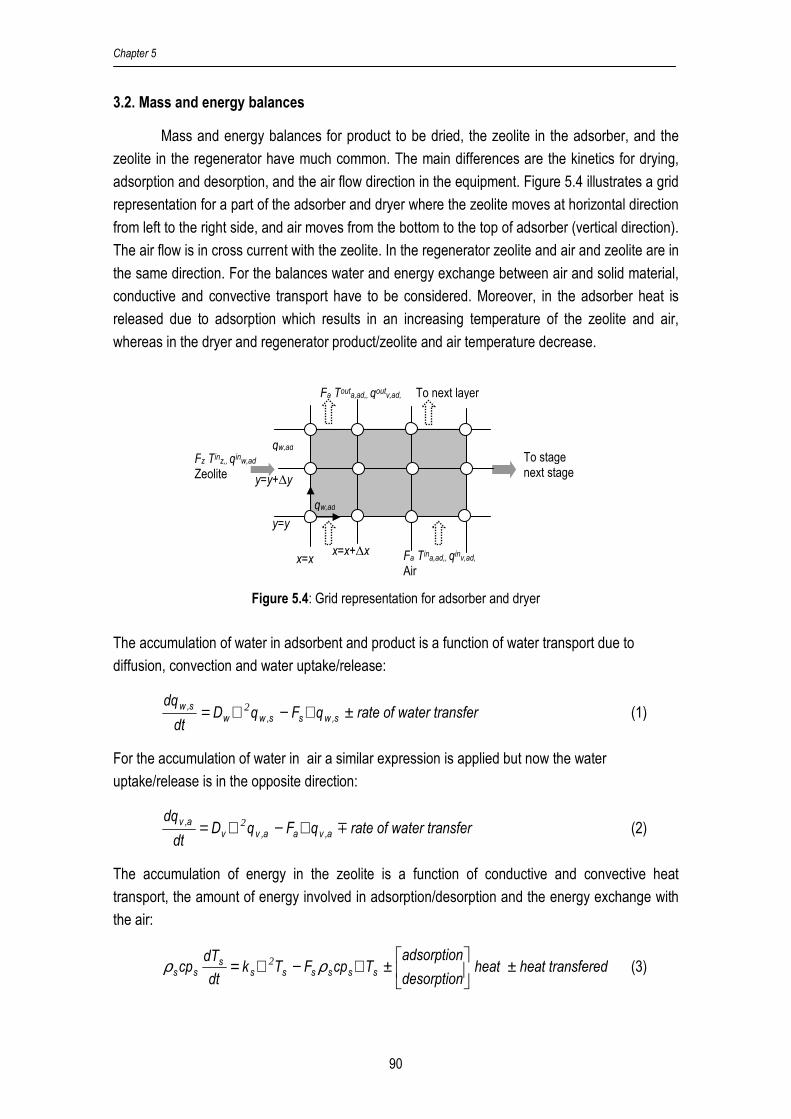
Chapter 5
90
3.2. Mass and energy balances
Mass and energy balances for product to be dried, the zeolite in the adsorber, and the
zeolite in the regenerator have much common. The main differences are the kinetics for drying,
adsorption and desorption, and the air flow direction in the equipment. Figure 5.4 illustrates a grid
representation for a part of the adsorber and dryer where the zeolite moves at horizontal direction
from left to the right side, and air moves from the bottom to the top of adsorber (vertical direction).
The air flow is in cross current with the zeolite. In the regenerator zeolite and air and zeolite are in
the same direction. For the balances water and energy exchange between air and solid material,
conductive and convective transport have to be considered. Moreover, in the adsorber heat is
released due to adsorption which results in an increasing temperature of the zeolite and air,
whereas in the dryer and regenerator product/zeolite and air temperature decrease.
Figure 5.4: Grid representation for adsorber and dryer
The accumulation of water in adsorbent and product is a function of water transport due to
diffusion, convection and water uptake/release:
erter transfrate of waqFqDdt
dqs,wss,ww
s,w ±∇−∇= 2 (1)
For the accumulation of water in air a similar expression is applied but now the water
uptake/release is in the opposite direction:
erter transfrate of waqFqDdt
dqa,vaa,vv
a,vm∇−∇= 2 (2)
The accumulation of energy in the zeolite is a function of conductive and convective heat
transport, the amount of energy involved in adsorption/desorption and the energy exchange with
the air:
feredheat trans heat desorption
adsorptionTcpFTk
dt
dTcp ssssss
sss ±
±∇−∇= ρρ 2 (3)
Fa Tina,ad,, qinv,ad, Air
qw,ad
Fa Touta,ad,, qoutv,ad,
To stage next stage
x=x x=x+∆x
y=y+∆y
y=y
qw,ad Fz Tinz,, qinw,ad Zeolite
To next layer

Computational Fluid Dynamics for Multistage Adsorption Dryer Design
91
The accumulation of energy in air is a function of conductive and convective heat transport and
the energy exchange with the zeolite:
transferedheatTcpFTkdt
dTcp aaaaaa
aaa m∇−∇= ρρ 2 (4)
Equations 1 to 4 are the basis for the formulation of the full model for each unit in the process. All
balances are given in equations A.1 to A.27, in Appendix 5.
3.3. Equipment dimensions, boundary and initial conditions
The dimensions and operation conditions are chosen in such way that the applied
conditions are comparable with previous work of Djaeni et al.[5] The equipment considered in the
calculations concerns four adsorbers and four drying stages with a total length of 2 m (i.e. 0.5
m/stage), the height of adsorbent bed is 0.2 m and the same value for the height is taken for the
dryer, the width for dryer and adsorber is 0.5 m. For the regenerator a length of 2 m is chosen, a
height of 0.2 m, and also a width of 0.5 m.
The CFD model for dryer and adsorber is realized by two connected layers: the lower
layer represents the adsorber and the upper layer the dryer. Air is not mixed between the
adsorber and dryer. The exhaust air from a dryer stage and which is fed to the next adsorber
stage is mixed. The CFD-model for the regenerator is realized by a separate unit which is fed by
the zeolite from the adsorber, and heated air. The air flow for regeneration is 80% of the air flow
through the adsorber and dryer.
The boundary conditions for each stage are given in Table A-1, Appendix 5. For the
calculations constants process parameters and the initial conditions depicted in Table A-2 and
Table A-3, are used (see Appendix 5). The operation conditions for each stream are given in
Table A-4, Appendix 5.1.
3.4. Energy efficiency
The standard definition for energy efficiency of drying processes is the ratio between the
heat required to evaporate water from the product and the total heat used in the system:
%Q
Q
req
evap 100=η (5)
voutd,w
ind,wpevap H)qq(FQ ∆−= (6)

Chapter 5
92
The required heat (req
Q ) corresponds to the sum of heat needed to heat ambient air
which is fed to the adsorber ( in
,adQ 1 ) and the heat needed to heat the air for the regenerator (
req
rQ )
minus the total heat that is recovered.
recreqr
in,adreq QQQQ −+= 1 (7)
)TT)(qcpcp(FQ ambinad,a
inad,vvaad,a
in,ad −+=1 (8)
Fresh air for the regenerator is pre-heated by air leaving the regenerator. The
temperature level of the preheated air is 10°C below the temperature at the outlet of the
regenerator (using minimum driving force for heat transfer 10°C).[14] The preheated air is then
heated further to the required temperature level for regeneration. The remaining heat to heat up
air entering regenerator ( reqrQ ) is given by:
)TT)(qcpcp(FQ outr,a
inr,a
inr,vvar,a
reqr 10−−+= (9)
Heat recovery is calculated from the amount of zeolite that leaves the regenerator and
the required inlet adsorber temperature, as follow:
)TT)(qcpcp(FQ inad,z
outr,z
outr,wwzzrec −+= (10)
3.5. Simulation method
Equations A.1-A.27 in Appendix 5, which are partial differential equations, were solved
with COMSOL, whereas the remaining equations for efficiency calculation (5-10) were processed
separately in Excel. The calculations with COMSOL concern a dynamic model and give the
development of the profiles in time and the steady-state profile in the system. The results in this
work concern the steady-state profiles.
4. Results and Discussion
4.1. Vapor and air temperature profiles in adsorber and dryer
Figures 5.5 presents the distribution of vapor and temperature of air in the adsorber and
dryer for the multistage dryer with a continuous moving bed of zeolite (CMBZ-DRYER), Figure 5.6
for multistage dryer with a discrete bed of zeolite (DBZ-dryer) .
The adsorber, where vapor in the air is adsorbed by the zeolite, has the opposite
temperature and vapor content profiles as the dryer where water evaporates from the product. In
the first adsorber the vapor content in the air decreases in the direction of the air flow (y-
direction). At the output of the first adsorber (y=0.2 m), about 70% of the initial vapor content in
the air is removed (see Figure 5.5 part a). This result is below the aimed design value of 80-90%
due to:

Computational Fluid Dynamics for Multistage Adsorption Dryer Design
93
1. In steady-state operation of the total system, the recycled zeolite fed to the first adsorber is
not totally free of water (containing 0.02 kg water/kg zeolite, see also Figure 5.7) and as a
result the driving force for adsorption is reduced.
2. Air flow of 1091 kg/hr (1.2 m/sec without porosity) is high for an adsorber bed of 0.2 m
diameter. As a result the contact time between the zeolite and air is not sufficient. The
dehumidification efficiency can be increased by a thicker layer of zeolite and by lowering
the linear air velocity.
Adsorption releases heat which results in a temperature increase of the air over the
adsorber (see Figure 5.5 part b). The air at the top of the adsorber has a temperature of 70°C,
which is 5-6°C below the temperature of the zeolite at the same position.
Leaving the first adsorber the air enters the dryer where the vapor content of the air
increases due to drying. The temperature of the air declines since the sensible heat is used to
heat the product and to evaporate water from the product. As a result, at the top of dryer, the
vapor content in the air is the highest and temperature the lowest.
In the following adsorbers (2, 3, 4) the air that leaves the previous drying stage contacts
the zeolite and here the vapor content decreases again and the temperature increases. In the
dryer with a continuous moving bed of zeolite (CMBZ-dryer) the air contacts zeolite from a
previous adsorber stage. The gradually increasing vapor content over the succeeding adsorber
stages causes a decreasing driving force for adsorption. As a result, the vapor uptake from the air
is below that of stage 1. Another consequence is a lower release of heat in the succeeding
adsorber stages and thus the temperature for drying decreases over the succeeding stages. At
the last stage the temperature of the air leaving the last adsorber stage is about 35-40°C.
The gradually decreasing temperatures and increasing air moisture content after each
adsorber stage affect the drying efficiency in the succeeding drying stages. The increased relative
humidity of the air gives a higher value for the equilibrium moisture content of the product (see
equation A-16) and thus a lower driving force for drying. For thicker layers vapor uptake is higher.
For the dryer with a discrete bed of zeolite (DBZ-dryer), the results are different ( see
Figure 5.6). Now the air contacts for every stage fresh zeolite with a low water content. The
driving force is now higher than that for the CMBZ-dryer. The dehumidification efficiency over all
adsorption stages is better and temperature increases. Air leaving each adsorber has always a
temperature above 50°C. However, it must be noted that the performance of adsorber decreases
with the stage number. This outcome is result of the gradual increasing vapor content of the air
over the succeeding stages.
For the CMBZ-dryer and DBZ-dryer systems, the efficiency differs for each stage. The
first stage with the highest temperature of air and the lowest zeolite moisture content has the best
performance for adsorption and drying. The performance, however, declines with the stage

Chapter 5
94
number. For the applied conditions and referring to Figure 5.5 and 5.6 a 2-3 stage adsorption and
drying is most efficient.
a.
b.
Figure 5.5: Vapor and air temperature distributed in multistage dryer with a Continuous Moving Bed of
Zeolite (CMBZ-dryer) where part a is for vapor and part b is for air temperature; CMBZ-dryer
at 2.00 −=y ; multi stage dryer for 4.02.0 −=y

Computational Fluid Dynamics for Multistage Adsorption Dryer Design
95
a.
b.
Figure 5.6: Vapor and air temperature distributed in multistage dryer with a Discrete Bed of Zeolite (DBZ-
dryer) where part a is for vapor and part b is for air temperature; DBZ-dryer at 2.00 −=y ;
multi stage dryer for 4.02.0 −=y
4.2. Distribution of water in zeolite for adsorber
The water content and temperature profiles over the adsorber units in the CMBZ-dryer
with the zeolite flow 120 kg/hr (dry basis) and total length of adsorber 2.0 m are given in Figure
5.7. Figures 5.8 gives the water content and temperature of DBZ-dryer with a zeolite flow of 30
kg/hr and adsorber length 0.5 m per stage. The pattern for the other adsorbers are similar.
The CMBZ-dryer and DBZ-dryer systems have a comparable residence time of the
zeolite. For both systems the zeolite water content at the exit of the last adsorber achieves with
0.12-0.13 kg water/kg dry zeolite. This value is 60-65% of the maximum zeolite capacity (0.2 kg
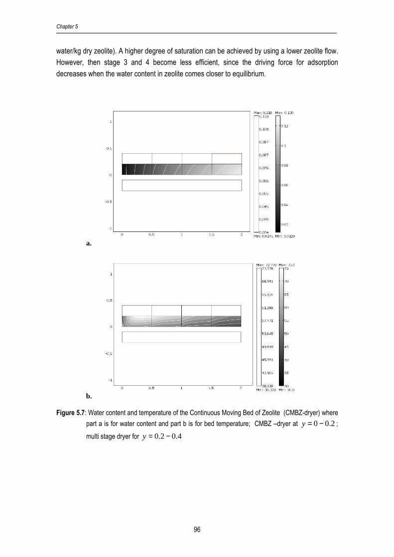
Chapter 5
96
water/kg dry zeolite). A higher degree of saturation can be achieved by using a lower zeolite flow.
However, then stage 3 and 4 become less efficient, since the driving force for adsorption
decreases when the water content in zeolite comes closer to equilibrium.
a.
b.
Figure 5.7: Water content and temperature of the Continuous Moving Bed of Zeolite (CMBZ-dryer) where
part a is for water content and part b is for bed temperature; CMBZ –dryer at 2.00 −=y ;
multi stage dryer for 4.02.0 −=y

Computational Fluid Dynamics for Multistage Adsorption Dryer Design
97
a.
b.
Figure 5.8: Water content and temperature of the Discrete Bed of Zeolite (DBZ-dryer) where part a is for
water content and part b is for bed temperature; DBZ-dryer at 2.00 −=y ; multi stage dryer
for 4.02.0 −=y
4.3. Distribution of water in product for dryer
Figures 5.9 and 5.10 present the profiles for the product water content and temperature
of product in the dryer for both systems (CMBZ-dryer and DBZ-dryer) with counter current flow of
zeolite and product (product from right to the left, and zeolite in the opposite direction). In stage 1,
product contacts air with the lowest amount of water and the highest temperature. This make that
in stage 1, despite the foregoing drying stages for the product (4, 3 and 2), the driving force for
drying is the highest. Consequently, stage 1 is the most efficient one. In stage 4, 3 and 2 drying is
less efficient, since in these stages the water content of the air is higher and the temperature

Chapter 5
98
lower. As a result the driving force and drying rate go down in these stages. The product water
content distribution is not as homogenous as in the zeolite. This means that the drying rate
decreases with the height in the dryer
a.
b.
Figure 5.9: Water content and temperature of product for multistage dryer with a Continuous Moving Bed
of Zeolite (CMBZ-dryer) where part a is for water content and part b is for bed temperature;
CMBZ-dryer at 2.00 −=y ; multi stage dryer for 4.02.0 −=y
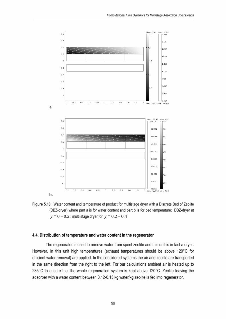
Computational Fluid Dynamics for Multistage Adsorption Dryer Design
99
a.
b.
Figure 5.10: Water content and temperature of product for multistage dryer with a Discrete Bed of Zeolite
(DBZ-dryer) where part a is for water content and part b is for bed temperature; DBZ-dryer at
2.00 −=y ; multi stage dryer for 4.02.0 −=y
4.4. Distribution of temperature and water content in the regenerator
The regenerator is used to remove water from spent zeolite and this unit is in fact a dryer.
However, in this unit high temperatures (exhaust temperatures should be above 120°C for
efficient water removal) are applied. In the considered systems the air and zeolite are transported
in the same direction from the right to the left. For our calculations ambient air is heated up to
285°C to ensure that the whole regeneration system is kept above 120°C. Zeolite leaving the
adsorber with a water content between 0.12-0.13 kg water/kg zeolite is fed into regenerator.

Chapter 5
100
Figures 5.11 and 5.12, give the distribution of water content and temperature of zeolite
temperature in regenerator for multistage dryer with CMBZ-dryer and DBZ-dryer, respectively.
The results for the discrete cycle adsorber system are similar because the regeneration system is
based on the same method.
a.
b. Figure 5.11: Water content and temperature of zeolite in regenerator for a Continuous Moving Bed of
Zeolite (CMBZ-dryer) where part a is for water content and part b is for bed temperature

Computational Fluid Dynamics for Multistage Adsorption Dryer Design
101
a.
b.
Figure 5.12: Water content and temperature of zeolite in regenerator for a Discrete Bed of Zeolite (DBZ-
dryer) adsorber where part a is for water content and part b is for bed temperature
The temperature of the zeolite increases in the first centimeters of the regenerator,
reaches a maximum and goes down in the transport direction. In the first centimeter, the hot air is
at highest temperature, and sensible heat of hot air is only used for heating up zeolite. While, at
the next position corresponding to transport direction, the heat is for heating zeolite and
evaporating water in zeolite that cause air temperature become lower than that of first centimeter.
As a consequence, the temperature of zeolite also decreases proportional with hot air
temperature (as heat source). In this case, using overall heat transfer coefficient from literature[15],
the temperature of zeolite at transport direction can close to hot air temperature. The results also
showed that the zeolite and air temperatures at the exit of the regenerator are above 160°C,
which indicates that regeneration runs well. The water content in the zeolite reduces about 80%
from inlet value and ends at the 0.02 kg water/kg dry zeolite. This value corresponds to the inlet

Chapter 5
102
value for water content of zeolite fed to the adsorber. Both air and zeolite leaving the regenerator
are reused to heat up cold streams of ambient air used for regeneration and drying
5. Discussion
5.1. Comparing the two systems
The continuous moving bed adsorber and discrete cycle adsorber show similar
phenomena in terms of their profiles for water content in zeolite, air and product and temperature.
Hence, the performance of both systems with respect to energy efficiency is quite close. For the
chosen equipment dimensions and operating conditions, the heat efficiency is 90.0% for a
multistage dryer with a continuous moving bed of zeolite (CMBZ-dryer), and 89.8% for a discrete
bed of zeolite (DBZ-dryer). These results imply that for both cases the total heat used to
evaporate water produced from adsorber and the total heat introduced to regenerate zeolite are
comparable. It is expected that the construction of the discrete cycle adsorber is more complex
than that of the continuous moving bed adsorber. Therefore, the following discussion is focused
only on the continuous moving bed adsorber system.
5.2. Energy efficiency
The energy efficiency for counter and co current zeolite dryers obtained for the two
dimensional model for the continuous moving bed adsorber is given in Figure 5.13 (dashed line).
In the same figure, the results for the lumped overall model used in previous work [5] is given by
the lines.
In the counter-current process, the fresh product contacts air from the last adsorber with
an increased relative humidity and a low temperature. The fresh product in stage 4 and 3 is
somewhat heated which is sufficient to dry the wet product. In the co-current dryer, the product
and air move in the same direction. In first dryer stage the product is directly contacted with the
air from the first stage adsorber, while for the following stages the product is dried by air from
other adsorber stages. The driving force for drying along the stage declines. In stage 4 the drying
efficiency is low because of the low drying temperature, high air moisture content and the low
moisture in the product. Both models (the two dimensional and steady state model) show that
energy efficiency of the co-current dryer is below that of the counter current dryer.
The dryer energy efficiency from the two dimensional counter-current model is close to
the results obtained in the previous work. [5] Main reasons for the differences are:
1. heat recovery system in the two dimensional model uses a slightly different direct match
since in this case, only two heat exchangers are used for heat recovery [1]

Computational Fluid Dynamics for Multistage Adsorption Dryer Design
103
2. steady-state lumped model uses fresh zeolite in every stage, while in the current system
the zeolite in the adsorber zeolite comes from a previous stage which results in a lower
effectiveness for adsorption.
3. In previous work the zeolite fed to the adsorber was water free and full saturation was assumed after adsorption, while in this case zeolite is not completely free of water. But
after taking into account heat released from adsorption and heat required for regeneration,
the total efficiency can be comparable
4. In the two dimensional system, the equilibrium sorption-isotherm is a function of the bed
height, whereas at previous model[5] the bed height was not included.
For the counter current zeolite dryer, the effects are negligible. The energy efficiency for the two
dimensional co-current model is slightly below that of the steady-state lumped model.
The number of stages has a strong effect on system performance. For the counter-
current system the efficiency increases from 80-90% by extending stage the number of stages
from 2 to 4. For the co-current system, the efficiency does not change above 3 stages.
74
76
78
80
82
84
86
88
90
92
2.00 3.00 4.00
Number of Stage
Hea
t effi
cien
cy (
%)
SS-Cocurrent
2D-Cocurrent
SS-Counter
2D-Counter
Figure 5.13: Estimated energy efficiency for counter and co-current systems for a different number of
stages. Comparing results form the lumped and two dimensional models.
The applied operational conditions for the applied equipment dimensions yield a total
product residence time (70-75 minutes) which is comparable to experimental results for drying
tarragon leafs which need 75-90 minutes (Arabhosseini et al. [12]). The residence time of zeolite is
about 65 minutes and the residence time of air dryer for one stage of adsorption and drying is
about 0.006 minutes. So, the total residence time of air is around 0.024 minutes. Using these
data, for further application, the dimension of equipments can be estimated corresponding to the
product capacity.

Chapter 5
104
5.3. The effect air to product ratio
The system has 33 equations (27 from equations A.1 to A.27, and 6 from equations 5 to
10) with 33 dependent variables and 12 independent variables (see Table A-3). So, there are
many possibilities to optimize the system. This discussion on optimization potential is here
restricted to the air to product ratio as design variable.
Figure 5.14 shows the results of efficiency calculations for a counter current dryer for which
the flow of product is varied from 15 to 27.5 kg/hr (50-90 kg/hr wet basis) while the air flow is kept
constant at 1091 kg/hr. The maximum efficiency (88-90%) is achieved at an air to product ratio
around 14-15 kg air/kg wet product or water carried capacity 0.035 kg water/kg air. The value is
higher to other dryers given in literatures which range from 0.003 to 0.025 depending on type of
dryer and product (Arabhosseini, 0.003;[16] Krokida and Bisharat, 0.025;[17] Holmberg and Ahtila,
0.01;[18] Baker et al, 0.025;[19] and Temple, 0.017[20]).
For the adsorption dryers using zeolite, higher air to product ratios are not effective since
the air is not able to take more water from the product. If the air to product ratio falls below 14 the
product is not enough heated. As a consequence the air temperature is lower, the product
equilibrium water content goes up and thus the driving force for drying and drying rate decreases.
80.00
81.00
82.00
83.00
84.00
85.00
86.00
87.00
88.00
89.00
90.00
91.00
10 12 14 16 18 20 22
Air to Product Ratio (kg/kg)
Effi
cien
cy (
%)
Figure 5.14: Effect of air to product ratio on the energy efficiency at ratio of air drying flow to air
regeneration flow 4:1
6. Conclusion
Steady-state mass balance calculations for a multistage adsorption dryer using zeolites,
presented in a previous study of Djaeni et al [5], were based on an overall model. In those
calculations equipment dimensions were not included and knowledge about the product kinetics
was not used. Moreover, such an overall model assumes that the spatial distribution has no effect
on the mass and heat transport.

Computational Fluid Dynamics for Multistage Adsorption Dryer Design
105
To take the next step ahead in the specification of the dryer dimensions and to
incorporate the drying and adsorption/desorption kinetics CFD calculations were performed for a
combined adsorber-dryer-regenerator system. The calculations showed:
1. The two-dimensional CFD model gives the internal temperature and water content
distribution of all units (dryer, adsorber and regenerator) and reveals characteristic
phenomena.
2. The energy efficiency obtained from the CFD calculations is close to the results obtained
from the overall steady state model. However, the CFD calculations reveal relevant
additional information about temperature and water content profiles. These profiles make it
possible to understand the internal phenomena, to find bottlenecks and to improve the
design.
3. The continuous moving bed adsorber dryer and the discrete cycle adsorber dryer have
comparable energy efficiency performance. The construction of the continuous moving bed
adsorber might be less complicated than that of the discrete cycle adsorber and can be
preferred for this reason.
4. The amount of vapor adsorbed in the adsorber and the amount of water evaporated in the
dryer is influenced by the height of the equipment. The height of the adsorber material is an
important variable in design because it results in more water adsorption and, as a result the
capacity and the water uptake rate of the dryer improve.
5. The quantity of water that can be adsorbed and the quantity of water removed from the
product is affected by the lengths of the adsorber and dryer. It results in a maximum of
effective stages. For the proposed capacity and the considered product, 2-3 stages satisfy.
The CFD calculations are powerful to estimate the dimensions and type of equipment for
industrial applications of multistage drying. The technical realization and operation of a multistage
dryer with a continuous moving bed of zeolite (CMBZ-dryer) is feasible.
Acknowledgement
This work is funded by the staff training program (TPSDP) of the Chemical Engineering
department of the Diponegoro University, Semarang Indonesia, and NEOT01005 project, Energy
Research Program EOS of the Dutch Ministry of Economics.
References
1. Djaeni, M.; Bartels, P.; Sanders, J.; Straten, G. van; Boxtel, A.J.B. van. Heat efficiency of
multistage zeolite system for low temperature drying. In Proceedings of The 5th Asia-Pacific
Drying Conference; Hong Kong, August 13-15, 2007, 589-594
2. Djaeni, M.; Bartels, P.; Sanders, J.; Straten, G. van; Boxtel, A.J.B. van. Process integration
for food drying with air dehumidified by zeolites. Drying Technology 2007, 25 (1), 225-239
Chapter 5
106
3. Ratti C. Hot air and freeze-drying of high-value foods: a review. Journal of Food
Engineering 2001, 49, 311-319
4. Revilla, G.O.; Velázquez, T.G.; Cortés, S.L.; Cárdenas, S.A. Immersion drying of wheat
using Al-PILC, zeolite, clay, and sand as particulate media. Drying Technology 2006, 24(8),
1033-1038
5. Djaeni, M.; Bartels, P.; Sanders, J.; Straten, G. van; Boxtel, A.J.B. van. Multistage Zeolite
Drying for Energy-Efficient Drying. Drying Technology 2007, 25 (6) 1063-1077
6. Wanjari, A.N.; Thorat, B.N.; Baker, C.G.J.; Mujumdar, A.S. Design and modeling of plug
flow fluid bed dryers. Drying Technology 2006, 24(2):147-157
7. Ahn, H.; Lee, C.H. Effects of capillary condensation on adsorption and thermal desorption
dynamics of water in zeolite 13X and layered beds. Chemical Engineering Science 2004,
59, 2727-2743
8. Leong, K.C.; Liu, Y. Numerical modeling of combined heat and mass transfer in the
adsorbent bed of a zeolite/water cooling system. Applied Thermal Engineering 2004, 24,
2359-2374
9. Kim, M.B.; Moon, J.H.; Lee, C.H.; Ahn H.; Cho, W. Effect of heat transfer on the transient
dynamics of temperature swing adsorption process. Korean J. Chem. Eng. 2004, 21(3),
703-711
10. Miltkau, T.; Dawoud, B. Dynamic modeling of the combined heat and mass transfer during
the adsorption/desorption of water vapour into/from a zeolite layer of an adsorption heat
pump. International Journal of Thermal Sciences 2002, 41, 753-762
11. Zhang, L.Z.; Wang, L. Momentum and heat transfer in the adsorbent of a waste-heat
adsorption cooling system. Energy 1999, 24(7), 605-624
12. Arabhosseini, A.; Huisman, W. ; van Boxtel, A.; Muller, J. Modeling of the Equilibrium
Moisture (EMC) Tarragon (Artemisia Dracunculus L.). International Journal of Food
Engineering 2005, 1(5), article 7
13. Anonymous. Siliporite data. CECA and ATO.
http://www.cecachemicals.com/sites/ceca/en/home.page (accessed September 26, 2008)
14. Linnhoff, B. User Guide of Process Integration for The Efficient Use of Energy; The Institution of Chemical Engineers: Rugby, UK, 1994
15. Jenkins S.A., Waszkiewicz S., Quarini G.L. and Tierney M.J. Drying saturated zeolite
pellets to assess fluidised bed performance. Applied Thermal Engineering 2002, 22, 861-
871
16. Arabhosseini, A.; Huisman, W. ; van Boxtel, A.; Müller, J. Long-term effects of drying
conditions on the essential oil and color of tarragon leaves during storage. Journal of Food
Engineering 2007, 79(2), 561-566
17. Krokida, M.K.; Bisharat, G.I. Heat recovery from dryer exhaust air. Drying Technology
2004, 22 (7): 1661-1674
18. Holmberg, H.; Ahtila, P. Comparison of drying costs in biofuel drying between multistage
and single-stage drying. Journal of Biomass and Bioenergy 2004, 26(6): 515-530

Computational Fluid Dynamics for Multistage Adsorption Dryer Design
107
19. Baker, C.G.J. ; Khan, A.R.; Ali, Y.I.; Damyar, K. Simulation of plug flow fluidized bed
dryers. Chemical Engineering and Processing 2006, 45(8): 641-651
20. Temple, S.J.; van Boxtel, A.J.B.; van Straten, G. Control of fluid bed tea dryers: controller
performance under varying operating conditions. Computers and Electronics in Agriculture
2000, 29(3), 217-231
Appendix 5
A.1. Adsorber
Water in Zeolite :
adsad,wzad,wwad,w
rqFqDdt
dq+∇−∇= 2 (A.1)
Water in air:
adsad,vaad,vvad,v
rqFqDdt
dq−∇−∇= 2 (A.2)
Temperature in zeolite bed:
)TT(UrHTcpFTkdt
dTcp ad,aad,zadadszadsad,zad,zzzad,zz
ad,zad,zz −−∆+∇−∇= ρρρ 2 (A.3)
Temperature of air in bed:
)TT(UTcpFTkdt
dTcp ad,aad,zadad,aad,aaaad,aa
ad,aad,aa −+∇−∇= ρρ 2 (A.4)
Water adsorption rate:
)qq(kr ad,wad,eadsads −= (A.5)
with [11]
).TR
Eexp(Ak
ad,a
adsadsads 15273
1
+−= (A.6)
and adeq , the equilibrium moisture for zeolite which is a function of air relative humidity (RH) and
temperature (T) according the modified Oswin equation:
210 1
C
ad
adad,aad,e )
RH
RH)(TCC(q
−+= (A.7)
C0, C1,C2 are obtained by fitting experimental data (see Table A-2).[12,13]
The heat capacities of air and zeolite in adsrober are:
ad,vvaad,a qcpcpcp += (A.8)
ad,wwzad,z qcpcpcp += (A.9)
Chapter 5
108
A.2. Dryer
Water in product:
dryd,wpd,wwd,w
rqFqDdt
dq−∇−∇= 2 (A.10)
Vapour in air:
dryd,vad,vvd,v
rqFqDdt
dq+∇−∇= 2 (A.11)
Temperature of product in dryer:
)TT(UrHTcpFTkdt
dTcp d,pd,addrypvd,pd,pppd,pp
d,p
d,pp −+∆−∇−∇= ρρρ 2 (A.12)
Temperature of air in dryer:
)TT(UTcpFTkdt
dTcp d,pd,add,ad,aaad,aa
d,ad,aa −−∇−∇= ρρ 2 (A.13)
where
)qq(kr d,wd,edrydry −= (A.14)
For the drying rate coefficient (kdry) and equilibrium moisture content cited form Arabhosseini are
used in the following equations [12]
)TCexp(Ak d,adrydrydry = (A.15)
543 1
C
d
dd,ad,e )
RH
RH)(TCC(q
−+= (A.16)
The heat capacities for product and air in dryer are:
d,wwpd,p qcpcpcp += (A.17)
d,vvad,a qcpcpcp += (A.18)
A.3. Regenerator
The mass and heat transport in the regeneration section are the opposite of that in the
adsorber section. However, some characteristic properties are related to the specific high
temperature conditions in the regenerator.
Water in zeolite:
desr,wzr,wwr,w
rqFqDdt
dq−∇−∇= 2 (A.19)
Water in air:
desr,varr,vvr,v
rqFqDdt
dq+∇−∇= 2 (A.20)

Computational Fluid Dynamics for Multistage Adsorption Dryer Design
109
Temperature of zeolite:
)TT(UrHTcpFTkdt
dTcp r,zr,ardesdeszdesr,zr,zzzr,zz
r,zr,zz −+∆−∇−∇= ρρρ 2 (A.21)
Temperature of air:
)TT(UTcpFTkdt
dTcp r,zr,ardesr,arr,aaarr,ara
r,arr,aa −+∇−∇= ρρ 2 (A.22)
where
)qq(kr r,wr,edesdes −= (A.23)
).TR
Eexp(Ak
r,ar
desdesdes 15273
1
+−= (A.24)
The desorption rate constant equals to adsorption rate constants (adsdesadsdes
EE;AA == , see
equation A.6). The equilibrium moisture is for temperatures above 100°C is given by the modified
Oswin equation.[12,13]
876 1
C
r
rr,ar,e )
RH
RH)(TCC(q
−+= (A.25)
The heat capacities of air and zeolite in regenerator are:
r,vvar,a qcpcpcp += (A.26)
r,wwzr,z qcpcpcp += (A.27)
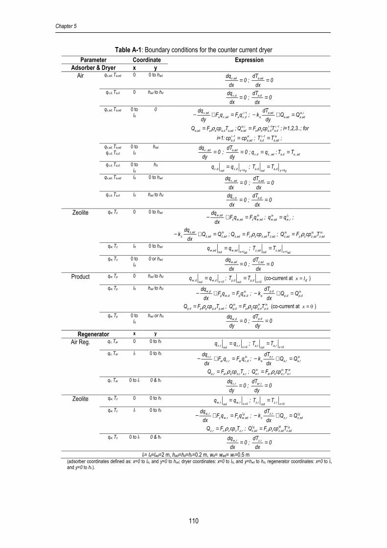
Chapter 5
110
Table A-1: Boundary conditions for the counter current dryer Parameter Coordinate
Adsorber & Dryer x y
Expression
qv,ad, Ta,ad 0 0 to had 0
dx
dq ad,v = ; 0dx
dT ad,a =
qv,d, Ta,d 0 had to hd 0
dx
dq d,v = ; 0dx
dT d,a =
qv,ad, Ta,ad 0 to ld
0 1i
d,vaad,va
ad,v qFqFdy
dq −=+− ; i,in
ad,aad,a
ad,a
a QQdy
dTk =+−
ad,ad,aaaad,a TcpFQ ρ= ; 1i
d,a
1i
d,aaa
i,in
ad,a TcpFQ −−= ρ ; i=1,2,3..; for
i=1: in
ad,a
1i
d,a cpcp =− ; in
ad,a
1i
d,a TT =− ;
qv,ad, Ta,ad qv,d, Ta,d
0 to ld
had 0
dy
dq ad,.v = ; 0dy
dT ad,a = ; ad,.vd,v qq = ; ad,.ad,a TT =
qv,d, Ta,d 0 to ld
hd dhyd,v
outd,v qq
== ;
dhyd,aout
d,a TT=
=
qv,ad, Ta,ad ld 0 to had 0
dx
dq ad,.v = ; 0dx
dT ad,a =
Air
qv,d, Ta,d ld had to hd 0
dx
dq d,v = ; 0dx
dT d,a =
qw; Tz 0 0 to had in
ad,wzad,wz
ad,wqFqF
dx
dq=+− ; rl
r,w
in
ad,w qq = ;
in
ad,zad,z
ad,z
z QQdx
dqk =+− ; ad,zad,zzzad,z TcpFQ ρ= ; in
ad,z
in
ad,zzz
in
ad,z TcpFQ ρ=
qw; Tz ld 0 to had adlxad,w
outad,w qq
== ;
adlxad,zout
ad,z TT=
=
Zeolite
qw; Tz 0 to ld
0 or had 0
dx
dq ad,w = ; 0dx
dT ad,z =
qw; Tp 0 had to hd 0xd,w
outd,w qq
== ;
0xd,p
outd,p TT
== (co-current at = dx l )
qw; Tp ld had to hd in
d,wpd,wp
p,wqFqF
dx
dq=+− ; in
d,pd,p
d,p
p QQdx
dTk =+−
ad,pd,pppd,p TcpFQ ρ= ; in
d,p
in
d,ppp
in
d,p TcpFQ ρ= (co-current at 0=x )
Product
qw; Tp 0 to ld
had or hd 0
dy
dq d,w = ; 0dy
dT d,p =
Regenerator x y qv; Tar 0 0 to hr
0xr,vout
r,v qq=
= ; 0xr,a
outr,a TT
==
qv; Tar lr 0 to hr in
d,varr,var
r,vqFqF
dx
dq=+− ; in
r,ar,a
r,a
a QQdx
dTk =+−
r,ar,aaarr,a TcpFQ ρ= ; in
r,a
in
r,aaar
in
r,a TcpFQ ρ=
Air Reg.
qv; Tar 0 to lr 0 & hr 0
dy
dq r,v = ; 0dy
dT r,ar =
qw; Tz 0 0 to hr 0xr,w
outr,w qq
== ;
0xr,zout
r,z TT=
=
qw; Tz lr 0 to hr dl
ad,wzr,wz
r,w qFqFdx
dq=+− ; dl
ad,zr,z
r,z
z QQdx
dTk =+−
r,zzzzr,z TcpFQ ρ= ; dl
ad,z
ld
ad,zzzdl
ad,z TcpFQ ρ=
Zeolite
qw; Tz 0 to lr 0 & hr 0
dx
dq r,w = ; 0dx
dT r,z =
lr= ld=lad=2 m, had=hd=hr=0.2 m, wd= wad= wr=0.5 m (adsorber coordinates defined as: x=0 to ld, and y=0 to had; dryer coordinates: x=0 to ld, and y=had to hd, regenerator coordinates: x=0 to lr, and y=0 to hr ).

Computational Fluid Dynamics for Multistage Adsorption Dryer Design
111
Table A-2: Used value for parameters Notation Parameter Value
Aads Adsorption rate factor, 1/sec 0.00404
Ades Desorption rate rate factor, 1/sec 0.00404
Adry Constant of drying rate (1/min) 0.0456/60
C0, C1,C2 Constant moisture equilibrium for zeolite < 100°C 0.24, 0.00, 0.023
C3, C4,C5 Constant moisture equilibrium for tarragon 0.131, -0.0005 , 0.50
C6, C7,C8 Constant moisture equilibrium for zeolite at higher 100°C 0.24, -0.0008, 0.023
cpa Specific heat of dry air (kJ/kg oC) 1.00
cpv Specific heat of vapor water (kJ/kg oC) 1.93
cpw Specific heat of liquid water (kJ/kg oC) 4.20
cpz Specific heat of dry zeolite (kJ/kg oC) 0.84
R/Eads Activation energy to constant ideal gas ratio, 1/oK 905.8
R/Edes Activation energy to constant ideal gas ratio, 1/oK 905.8
Edry Constant (1/oC) 0.0665
∆Hads Latent heat of water adsorption (kJ/kg) -3200
∆Hv Latent heat of water evporation (kJ/kg) 2500
RH Relative Humidity, % y,x The direction of x-y, coordinate in height and length
zd The width of bed, m 0.4
aρ Density of dry air, kg/m3 1.01
pρ Density of dry product, kg/m3 200
zρ Density of dry zeolite, kg/m3 1100
Table A-3: Initial conditions for the calculations Parameter Initial value at t=0, for all x and y
Water in zeolite adsorber, kg water/kg dry zeolite inad,w
0ad,w qq =
Temperature of zeolite in adsorber, °C inad,z
0ad,z TT =
Vapour in air adsorber, kg vapour/kg dry air inad,v
0ad,v qq =
Temperature of air in adsorber, °C inad,a
0ad,a TT =
Vapour in air dryer, kg vapour/kg dry air 005.0q0 d,v =
Temperature of air in dryer, °C 50T 0d,a =
Water in product dryer, kg water/kg dry product ind,w
0d,w qq =
Temperature of product in dryer, °C ind,p
0d,p TT =
Water in zeolite regenerator, kg water/kg dry zeolite inr,w
0r,w qq =
Temperature of zeolite in regenerator, °C inr,z
0r,z TT =
Vapor in air regenerator, kg vapour/kg dry air inr,v
0r,v qq =
Temperature of air in regenerator, °C inr,a
0r,a TT =

Chapter 5
112
Table A-4: Conditions for each flow Parameter notation value
Flow of dry zeolite to adsorber, kg/hr zF 120
Temperature of zeolite to adsorber, °C inad,zT 35
Flow of dry air to adsorber/dryer, kg/hr aF 1091
Temperature of air to adsorber, °C inad,aT 25
Vapour in air to adsorber, kg vapour/kg dry air inad,vq 0.01
Flow of dry zeolite to regenerator, kg/hr zF 120
Flow of dry air to regenerator/dryer, kg/hr arF 873
Temperature of air to regenerator, °C inr,aT 285
Vapour in air to regenerator, kg vapour/kg dry air inr,vq 0.01
Flow of dry product to dryer, kg/hr pF 15-27.5
Temperature of product to dryer, °C ind,pT 25
Water in product to dryer, kg water/kg dry product ind,wq 2.5

Chapter 6
Performance Evaluation of Adsorption
Dryer Using Zeolite

Chapter 6
114
Abstract
The potential energy efficiency improvement for single-stage drying with air dehumidification by
zeolite is validated experimentally. The experimental results are fitted to a dynamic model which
is used to find important variables for the operation of the zeolite dryer. The ratio between air flow
for drying and air flow for regeneration affect the energy efficiency significantly, just like the
ambient air temperature. Relative humidity of used air and shift time have a minor effect on the
dryer performance. The results show that with the single-stage zeolite dryer energy efficiencies of
75% can be achieved.
Keywords: drying, adsorption, regeneration, energy efficiency, zeolite

Performance Evaluation of Adsorption Dryer Using Zeolite
115
List of symbols
A cross sectional area (m2)
n,..2,1C equilibrium and kinetic constant
F flow of dry component (kg/min) G flow of wet component (kg/min) ID internal diameter (m) P total pressure (bar) Q heat flow (kJ/min) R gas constant (kJ/kmole K) RH relative humidity (%) Spa specific surface area (m2/kg) T temperature (oC) U overall heat transfer coefficient (kJ/m2 min °C) V volume (m3) cp specific heat (kJ/kg°C)
h height in adsorbent (m)
regdad h,h,h total height of adsorber, dryer, regenerator (m)
k constant of water transfer rate (1/min)
dl length of dryer (m)
q moisture content in dry matter (kg moisture/kg dry matter)
r rate of water transfer (kg water/kg dry matter/ min) t time (min) tf final time (min)
dw width of dryer (m)
y vapor in air (kmole/kmole dry air)
H∆ latent heat of water change (kJ/kg) ρ density (kg/m3)
η energy efficiency (%)
ε porosity of material Subscripts a air ad adsorber ads adsorption amb ambient c cycle col column d dryer des desorption dry drying e equilibrium evap evaporation in inlet intr introduced max maximum out outlet p product reg regenerator rec recovery req required v vapour w water z zeolite

Chapter 6
116
1. Introduction
The drying capacity of the air to evaporate water from products is related to the relative
humidity of the air used for drying, which in turn depends on the vapor content and temperature of
the air. The drying capacity increases if the relative humidity decreases. In conventional drying
systems, the drying capacity is improved by increasing the air temperature or by decreasing the
pressure in order to reduce the relative humidity of air.[1] Both approaches are successful in
improving the driving force, but are unfavorable in terms of energy use and have other
drawbacks. The first approach is disadvantageous for drying of heat sensitive products for which
the maximum drying temperature is a constraint to retain product quality. The second approach
requires high investment and operational costs to create the low pressure.
An alternative to improve the drying capacity of air is by removing the vapor in the air
used for drying by condensation or by using adsorbents. [2,3,4] Removal of vapor dehumidifies the
air and thus improves the driving force for drying. Previous work showed that an adsorption dryer
(where air is dehumidified by using adsorbents) has a higher potential for the reduction of energy
usage and operational costs than a condensation dryer (where dehumidification based on
condensation) or freeze-drying.[2,4] The total costs (fixed and operational cost for energy supply)
of an adsorption dryer are about 50% below the total costs for a freeze-dryer [2] and the energy
efficiency of an adsorption dryer operated below 50oC is up to 15-20% higher than that of a
condensation dryer.[4] For drying at operation temperatures in the range of 60-80oC, the energy
usage of adsorption dryer using zeolite can be half of the energy usage of a standard dryer
working at comparable conditions.[5,6]
Experimental work has been conducted to study the potential and effectiveness of
several solid adsorbents for dehumidifying air to improve the driving force in drying processes.
Witinantakit et al[7] tested the performance of paddy (rice) husk as vapor adsorbent in paddy
drying and concluded that the drying rate was increased and a lower final paddy moisture content
could be achieved by using dehumidified air. Nagaya et al[8] improved the drying rate for
vegetables (cabbage, egg plants and carrots) using air dehumidified by silica and could retain
product quality attributes as color and vitamin. Revilla et al[9] studied immersion drying of wheat
using several adsorbents (alumina pillared clay, sand, and zeolite) to speed up water
evaporation, and Alikhan et al[10] evaluated the potential of zeolite as adsorbent for drying corn in
a rotary dryer. They found that zeolites have potential to increase the drying rate. Moreover, the
capability of zeolites (4Å, 5Å and 13X) to dehumidify air has been tested and the results indicated
that the vapor content in air can be reduced till a dew point of -60oC.[11] With this performance
zeolite yields a far better dehumidification compared to common adsorbents as silica and
alumina, and therefore zeolite is very important for adsorption drying[12]
Despite of the improvement of the drying rate and the release of adsorption heat, spent
zeolite needs heat for its regeneration before reuse for air dehumidification. Improvements in the
energy efficiency for the drying unit are (partly) cancelled by the energy requirement for
regeneration. In the literature there is a lack on information on the effectiveness of zeolite for the
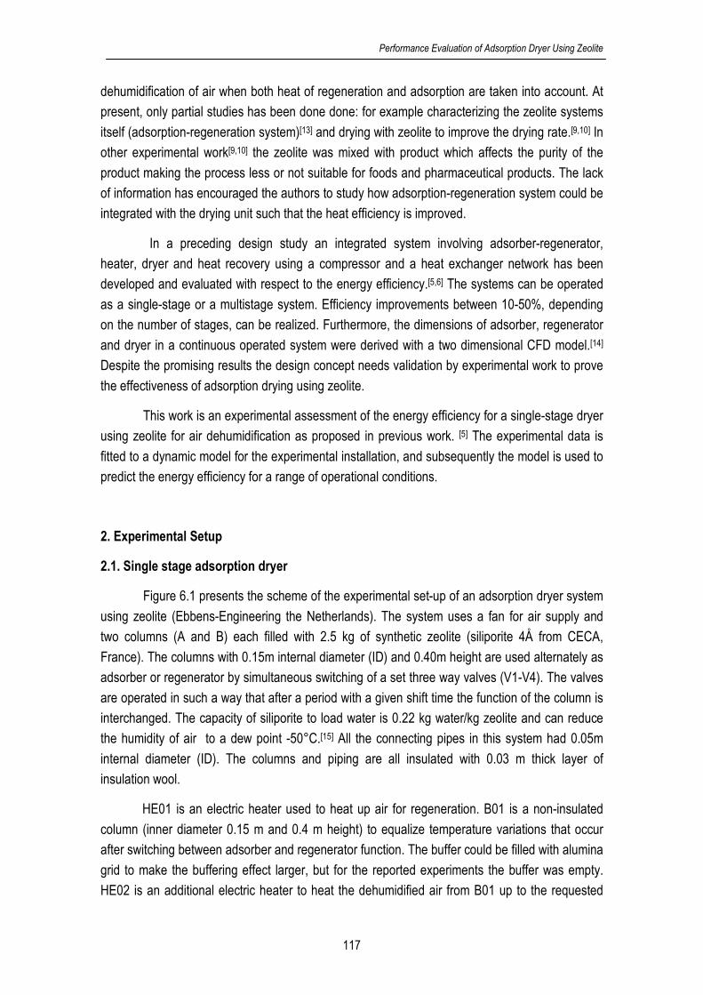
Performance Evaluation of Adsorption Dryer Using Zeolite
117
dehumidification of air when both heat of regeneration and adsorption are taken into account. At
present, only partial studies has been done done: for example characterizing the zeolite systems
itself (adsorption-regeneration system)[13] and drying with zeolite to improve the drying rate.[9,10] In
other experimental work[9,10] the zeolite was mixed with product which affects the purity of the
product making the process less or not suitable for foods and pharmaceutical products. The lack
of information has encouraged the authors to study how adsorption-regeneration system could be
integrated with the drying unit such that the heat efficiency is improved.
In a preceding design study an integrated system involving adsorber-regenerator,
heater, dryer and heat recovery using a compressor and a heat exchanger network has been
developed and evaluated with respect to the energy efficiency.[5,6] The systems can be operated
as a single-stage or a multistage system. Efficiency improvements between 10-50%, depending
on the number of stages, can be realized. Furthermore, the dimensions of adsorber, regenerator
and dryer in a continuous operated system were derived with a two dimensional CFD model.[14]
Despite the promising results the design concept needs validation by experimental work to prove
the effectiveness of adsorption drying using zeolite.
This work is an experimental assessment of the energy efficiency for a single-stage dryer
using zeolite for air dehumidification as proposed in previous work. [5] The experimental data is
fitted to a dynamic model for the experimental installation, and subsequently the model is used to
predict the energy efficiency for a range of operational conditions.
2. Experimental Setup
2.1. Single stage adsorption dryer
Figure 6.1 presents the scheme of the experimental set-up of an adsorption dryer system
using zeolite (Ebbens-Engineering the Netherlands). The system uses a fan for air supply and
two columns (A and B) each filled with 2.5 kg of synthetic zeolite (siliporite 4Å from CECA,
France). The columns with 0.15m internal diameter (ID) and 0.40m height are used alternately as
adsorber or regenerator by simultaneous switching of a set three way valves (V1-V4). The valves
are operated in such a way that after a period with a given shift time the function of the column is
interchanged. The capacity of siliporite to load water is 0.22 kg water/kg zeolite and can reduce
the humidity of air to a dew point -50°C.[15] All the connecting pipes in this system had 0.05m
internal diameter (ID). The columns and piping are all insulated with 0.03 m thick layer of
insulation wool.
HE01 is an electric heater used to heat up air for regeneration. B01 is a non-insulated
column (inner diameter 0.15 m and 0.4 m height) to equalize temperature variations that occur
after switching between adsorber and regenerator function. The buffer could be filled with alumina
grid to make the buffering effect larger, but for the reported experiments the buffer was empty.
HE02 is an additional electric heater to heat the dehumidified air from B01 up to the requested
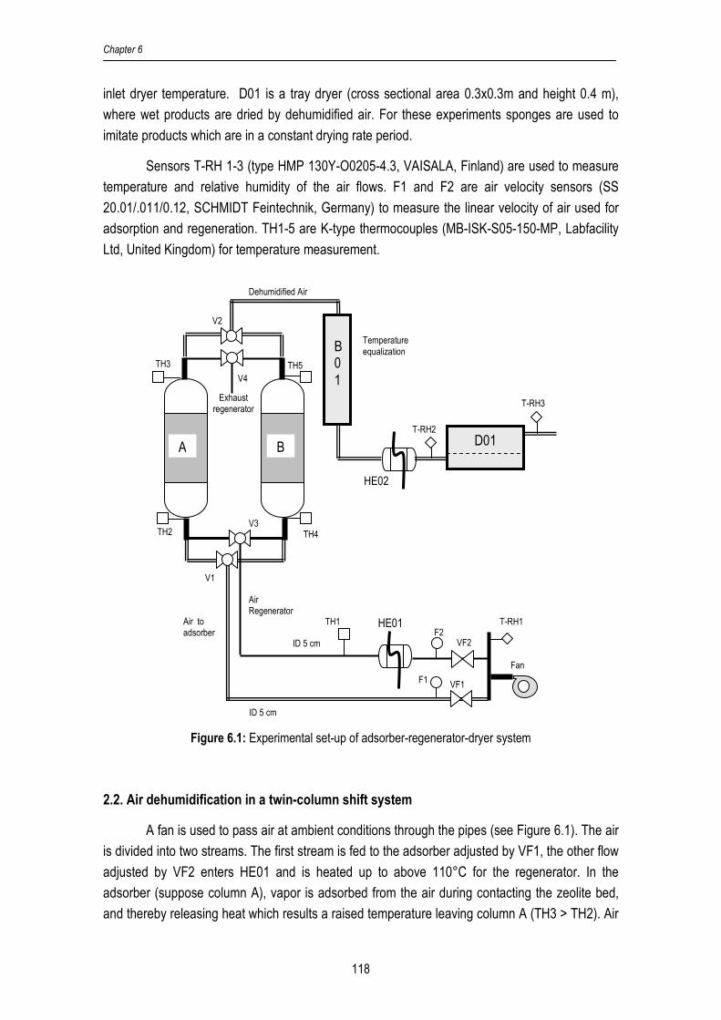
Chapter 6
118
inlet dryer temperature. D01 is a tray dryer (cross sectional area 0.3x0.3m and height 0.4 m),
where wet products are dried by dehumidified air. For these experiments sponges are used to
imitate products which are in a constant drying rate period.
Sensors T-RH 1-3 (type HMP 130Y-O0205-4.3, VAISALA, Finland) are used to measure
temperature and relative humidity of the air flows. F1 and F2 are air velocity sensors (SS
20.01/.011/0.12, SCHMIDT Feintechnik, Germany) to measure the linear velocity of air used for
adsorption and regeneration. TH1-5 are K-type thermocouples (MB-ISK-S05-150-MP, Labfacility
Ltd, United Kingdom) for temperature measurement.
Figure 6.1: Experimental set-up of adsorber-regenerator-dryer system
2.2. Air dehumidification in a twin-column shift system
A fan is used to pass air at ambient conditions through the pipes (see Figure 6.1). The air
is divided into two streams. The first stream is fed to the adsorber adjusted by VF1, the other flow
adjusted by VF2 enters HE01 and is heated up to above 110°C for the regenerator. In the
adsorber (suppose column A), vapor is adsorbed from the air during contacting the zeolite bed,
and thereby releasing heat which results a raised temperature leaving column A (TH3 > TH2). Air
TH2
TH3
HE01
HE02
ID 5 cm
ID 5 cm
A
V4
V2
V3
V1
F2
F1
TH1
TH4
TH5
B 0 1
D01
T-RH1
T-RH2
T-RH3
Fan
Exhaust regenerator
Air Regenerator
Air to adsorber
Dehumidified Air
Temperature equalization
VF2
VF1
B

Performance Evaluation of Adsorption Dryer Using Zeolite
119
is then passed though HE02 to reach the drying temperature. Leaving HE02, the dehumidified air
enters dryer (D01) to evaporate free water from the wet product.
Meanwhile, the hot air entering column B regenerates the spent zeolite. The hot air flow
evaporates water from the saturated zeolite and as a result the outlet temperature of the
regenerator is below the inlet temperature (TH5<TH4). The exhaust air from the regenerator is
not further used in this system, but from the measured temperature the heat recovery potential is
calculated.
At the end of a period with continuous air flow the zeolite in column A will become nearly
saturated with water. As a result, the adsorption effectiveness decreases. To continue air
dehumidification the air for drying is switched to the column B with dry zeolite, while the saturated
zeolite in column A is regenerated. As a consequence, the inlet and outlet point of adsorber-
regenerator are also moved from TH2-TH3 to TH4-TH5. The shift time is defined as the time
between successive switching instants.
2.3. Data collection
In the experimental system the shift time, temperature of air for dryer and regenerator are
manually controlled. The air flow is adjusted by regulating the valve positions VF1 for drying air,
and VF2 for regenerator air. A program developed in LABVIEW and running on a PC is used to
realize the setting values, to monitor drying, to collect experimental data and as a user interface.
The data is recorded every two seconds. The data concerns:
- linear velocity of dryer air and regenerator air (F1 and F2),
- temperature of air entering adsorber and regenerator (TH2 or TH4 depending on shift),
- temperature of air exiting adsorber and regenerator (TH3 or TH5 depending on shift),
- relative humidity and temperature of ambient air (T-RH1),
- air entering and exiting dryer (T-RH2 and T-RH3).
By combining experimental data, the dimension of the pipes and physical properties of the
components (air, zeolite, vapor, and water), the mass and energy flow of all the streams were
calculated at each sampling moment. The data is used to calculate the energy efficiency of the
system as presented in section 2.4.
Data was collected from the start-up of the installation. The first shift is regarded as a start shift
for heating the installation and to regenerate the zeolite. From this moment the data is used for
energy efficiency calculations, model fitting and validation.
Chapter 6
120
Experiments concerned shift times 30, 45 and 60 minutes. Ambient air was used for the
experiments. Temperature and humidity depended on the weather conditions and varied between
17-22°C, and 0.006-0.009 kg water/kg air. The inlet regeneration temperature was set to 140°C.
2.4. Energy efficiency calculation
The heat efficiency of system is calculated as follows:
Q
max,recrint
evap 100−
=η (1)
with evapQ as the total heat required for evaporating water in the dryer (kJ) which follows from the
inlet and outlet air humidity ( ind,vq , out
d,vq ), and the mass flow of dry air through the dryer ( d,aF ) . For
a total operational time tf , evapQ corresponds to:
dt)qq(HFQ
tft
0t
ind,v
outd,vevapd,aevap ∫
=
=
−∆= (2)
where the values of humidity ( ind,vq , out
d,vq ) are derived from the temperature and relative humidity
of air recorded over an experiment (T-RH2 and T-RH3). The mass flow of dry air ( d,aF ) is
calculated from the recorded air flow according:
ind,v
d,ad,a
q
GF
+=
1 (3)
with d,aG the mass flow of wet air (kg/minute) derived from the air velocity from F1 measurement
multiplied with the cross sectional area of the pipe and air density.
rintQ is total of heat introduced to system (kJ) and equals the heat supplied to the regenerator
and the heat to bring the dehumidified air from adsorber to the drying temperature:
dt))TT(cpF)TT(cpF(Q outad,a
ind,aad,aad,a
tft
t
ambinreg,areg,areg,arint −+−= ∫
=
=0
(4)
where ad,aF is the dry air flow entering the adsorber. It is equal to d,aF . reg,aF is calculated analog to
equation 3 using the data from measurement device F2, inreg,aT follows from TH2 or TH4
depending on the shift, ambT and ind,aT are measured by T-RH1 and T-RH2, respectively. Finally,
outad,aT is measured by TH3 or TH5 depending on the shift.

Performance Evaluation of Adsorption Dryer Using Zeolite
121
max,recQ is the calculated amount of heat which could be recovered from the exhaust air of the
regenerator (kJ). The recovery is based on a heat exchanger with 10°C temperature difference
between hot and cold stream. Using pinch technology as applied in previous work[4,5], the
maximum recovered heat is:
dt)TT(cpFQtft
t
amboutreg,areg,areg,amax,rec ∫
=
=
−−=0
10 (5)
Here, outreg,aT is measured from TH3 or TH5 depending on the shift.
3. Model Development
3.1. Assumptions
The model in the form of partial differential equations is set up to predict the energy
efficiency of the zeolite dryer for process conditions which are beyond the experimental range of
the installation. The model is based on mass and energy balances for air and solids in the
adsorber, regenerator and dryer. Figure 6.2 gives a schematic presentation of the flows.
Temperatures for air, zeolite and product, as well as moisture in air, zeolite and product are a
function of the vertical dimension (h). The balances consider moisture and energy exchange
between air and solid material and also heat loss due to temperature differences between the air
in the equipment and air in the environment. Moreover, heat released during adsorption and heat
required for regeneration is taken into account.
.
Figure 6.2: Spatial representation for adsorber, regenerator and dryer
h=h
h=h+∆h
Tz,ad(h,t); qw,ad(h,t)
Air: Fa, ad Ta,ad(h+∆h,t) ;qv,ad(h+∆h,t)
Tz,ad(h+∆h,t); qw,ad(h+∆h,t)
Solid layer
Gas phase
Mass/ Heat transfer
Air: Fa, ad Ta,ad(h,t);qv,ad(h,t)
Heat loss to surrounding

Chapter 6
122
The model is based on the following assumptions:
1. the flow of air through the bed of adsorbent is plug flow,
2. pressure drop over the equipment is neglected,
3. physical constants as density, specific heat, and diffusion coefficients are constant,
4. only the dynamics and spatial distribution in the adsorber, dryer and regenerator are
considered; responses for heater, and pipes are instantaneous,
5. the free water of imitated product in dryer is in excess and so that the dryer operates in a
constant drying rate period,
6. adsorption heat is equal to desorption heat,
7. the model includes heat loss from adsorber, regenerator and dryer to the environment,
8. buffer works quickly and perfectly during the operational time,
9. water and heat transport between zeolite and product particles take place through the air and not by particle contact.
3.2. Model formulation
The model includes the mass balances for liquid water, water vapor, and the heat
balances for zeolite, product and air temperature. These balances are based on the laws of
conservation for mass and energy. Table 6.1 presents the dynamic mathematical model
describing the phenomena in each equipment unit. The model is completed by the additional
equations as depicted in Table 6.2.

Performance Evaluation of Adsorption Dryer Using Zeolite
123
Table 6.1: Dynamic models of the adsorption dryer system Adsorber Mass balance of water
Zeolite: )t,h(rdt
)t,h(dqads
ad,w = (6)
Air: )t,h(r)1(dh
)t,h(dq)
A
F(
dt
)t,h(dq
adsz
a
zad,v
cola
ad,aad,v
z ερρ
ρε −−−= (7)
Heat balance
Zeolite: )))t,h(T)t,h(T((SU)t,h(rH)1(dt
)t,h(dT)1(cp
ad,aad,zz,Azadsadszz
ad,z
zad,zz −−∆−=− ερερ (8)
Air:
)T)t,h(T(ID
U4))t,h(T)t,h(T(SU
dh
)t,h(dT
A
cpF
dt
)t,h(dTcp ambad,a
col
col,bed
ad,aad,zz,Az
ad,a
ad
ad,aad,aad,a
zad,aa −−−+−=ερ (9)
Regenerator Mass balance of water
Zeolite: )t,h(rdt
)t,h(dqdes
reg,w = (10)
Air: )t,h(r)1(dh
)t,h(dq)
A
F(
dt
)t,h(dq
desz
a
zreg,v
cola
reg,areg,v
z ερρ
ρε −−−= (11)
Heat balance
Zeolite: )))t,h(T)t,h(T((SU)t,h(rH)1(dt
)t,h(dT)1(cp reg,areg,zz,Azdesdeszz
reg,z
zreg,zz −−∆−=− ερερ (12)
Air:
))..t,h(T)t,h(T(SUdh
)t,h(dT
A
cpF
dt
)t,h(dTcp
reg,areg,zz,Az
reg,a
col
reg,areg,areg,a
zreg,aa −+−=ερ
)T)t,h(T(ID
U4.. ambreg,a
col
col,bed −− (13)
Dryer Mass balance of water
product: )t,h(rdt
)t,h(dqdry
d,w −= (14)
Air: )t,h(r)1(dh
)t,h(dq)
A
F(
dt
)t,h(dq
dryp
a
pd,v
da
d,ad,v
p ερρ
ρε −−−= (15)
Heat balance
Product: )))t,h(T)t,h(T((SU)t,h(rH)1(dt
)t,h(dT)1(cp d,ad,pp,Apdryvpp
d,p
pd,pp −−∆−=− ερερ (16)
Air: )T)t,h(T(l
U))t,h(T)t,h(T(SU
dh
)t,h(dT
A
cpF
dt
)t,h(dTcp ambd,a
d
d,bed
d,ad,pp,Ap
d,a
d
d,ad,ad,a
pd,aa −−−+−=ερ (17)

Chapter 6
124
Table 6.2: Additional equations relating to equations 6 to 17 Adsorber ))t,h(q)t,h(q(k)t,h(r
ad,wad,eadsads −=
)15.273)t,h(T(Ck ad,z1ads +=
( )[ ]1)t,h(TC))t,h(P(logtanhC)t,h(q ad,z3ad,v102ad,e ++=
1132.0C2 = ; 0266.0C3 −=
The equilibrium moisture loaded in zeolite is a function of vapor partial pressure and temperature derived from zeolites properties in CECA data sheet[15].
total
ad,v
ad,v
ad,v P)t,h(y1
)t,h(y)t,h(P
+= ;
622.0/)t,h(q1
622.0/)t,h(qy
ad,v
ad,viad,v +
=
2
colcol )ID(4
Aπ= ; zz,paz,A SS ρ= ;
amb,v
ad,aad,a
q1
GF
+= ; acol1ad,a AFG ρ=
1F is linear velocity of air entering adsorber measured from F1
)t,h(qcpcpcpad,wwzad,z
+= ; )t,h(qcpcpcpad,vvaad,a
+=
Regenerator ))t,h(q)t,h(q(krreg,wreg,edesdes −=
)15.273)t,h(T(Ck reg,z4des +=
adsdes HH ∆=∆
)t,h(qcpcpcp reg,wwzreg,z+= ; )t,h(qcpcpcp reg,vvareg,a
+= ;
amb,v
reg,a
reg,aq1
GF
+= ; acol2reg,a AFG ρ=
2F is linear velocity of air entering regenerator measured from F2
Dryer 0ddry
kr −=
)t,h(qcpcpcpd,wwpd,p
+= ; )t,h(qcpcpcpp,vvad,a +=
ad,ad,a FF =
ddd lwA = ; dddd hlwV = ; dddpp,pap,A hlwSS ρ=
4. Model validation
4.1. Parameter estimation
Equations 6 to 17 with the additional equations depicted in Table 6.2 were solved using
the boundary and the initial conditions as given in Table A-1 (Appendix 6), and using the
equipment dimensions, material properties, and the process constants as given in Table A-2
(Appendix 6).
The measured values of the flows and inlet temperatures during operational time were
used as input data for the model. The model responses in time were fitted to the experimental
measured values of temperature and humidity of the air leaving the adsorber, temperature of air
leaving the regenerator, and temperature and humidity of air leaving the dryer. For response
fitting and parameter estimation Matlabs’ function fmincon is used.
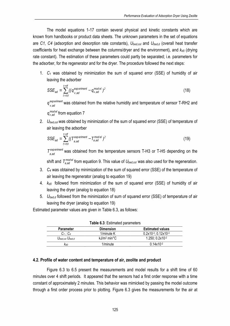
Performance Evaluation of Adsorption Dryer Using Zeolite
125
The model equations 1-17 contain several physical and kinetic constants which are
known from handbooks or product data sheets. The unknown parameters in the set of equations
are C1, C4 (adsorption and desorption rate constants), Ubed,col and Ubed,d (overall heat transfer
coefficients for heat exchange between the columns/dryer and the environment), and kd0 (drying
rate constant). The estimation of these parameters could partly be separated; i.e. parameters for
the adsorber, for the regenerator and for the dryer. The procedure followed the next steps:
1. C1 was obtained by minimization the sum of squared error (SSE) of humidity of air
leaving the adsorber
2
0
)qq((SSEtft
tt
elmodad,v
erimentexp
ad,vad ∑=
=−= (18)
erimentexp
ad,vq was obtained from the relative humidity and temperature of sensor T-RH2 and
elmodad,vq from equation 7
2. Ubed,col was obtained by minimization of the sum of squared error (SSE) of temperature of
air leaving the adsorber
2
0
)TT((SSEtft
tt
elmodad,a
erimentexp
ad,aad ∑=
=−= (19)
erimentexp
ad,aT was obtained from the temperature sensors T-H3 or T-H5 depending on the
shift and elmodad,aT from equation 9. This value of Ubed,col was also used for the regeneration.
3. C4 was obtained by minimization of the sum of squared error (SSE) of the temperature of
air leaving the regenerator (analog to equation 19)
4. kd0 followed from minimization of the sum of squared error (SSE) of humidity of air
leaving the dryer (analog to equation 18)
5. Ubed,d followed from the minimization of sum of squared error (SSE) of temperature of air
leaving the dryer (analog to equation 19)
Estimated parameter values are given in Table 6.3, as follows:
Table 6.3: Estimated parameters
Parameter Dimension Estimated values
C1 ; C4 1/minute K 0.2x10⁻³; 0.12x10⁻³
Ubed,col Ubed,d kJ/m2 min°C 1.250; 0.2x10⁻²
kd0 1/minute 0.14x10⁻²
4.2. Profile of water content and temperature of air, zeolite and product
Figure 6.3 to 6.5 present the measurements and model results for a shift time of 60
minutes over 4 shift periods. It appeared that the sensors had a first order response with a time
constant of approximately 2 minutes. This behavior was mimicked by passing the model outcome
through a first order process prior to plotting. Figure 6.3 gives the measurements for the air at
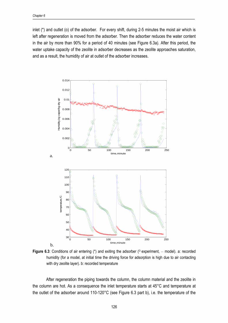
Chapter 6
126
inlet (*) and outlet (o) of the adsorber. For every shift, during 2-5 minutes the moist air which is
left after regeneration is moved from the adsorber. Then the adsorber reduces the water content
in the air by more than 90% for a period of 40 minutes (see Figure 6.3a). After this period, the
water uptake capacity of the zeolite in adsorber decreases as the zeolite approaches saturation,
and as a result, the humidity of air at outlet of the adsorber increases.
a. 0 50 100 150 200 250
0
0.002
0.004
0.006
0.008
0.01
0.012
0.014
time,minute
Hum
idity
,kg
vapo
r/kg
dry
air
b.0 50 100 150 200 250
30
40
50
60
70
80
90
100
110
120
time,minute
tem
pera
ture
,°C
Figure 6.3: Conditions of air entering (*) and exiting the adsorber (O experiment, __ model). a: recorded
humidity (for a model, at initial time the driving force for adsorption is high due to air contacting
with dry zeolite layer). b: recorded temperature
After regeneration the piping towards the column, the column material and the zeolite in
the column are hot. As a consequence the inlet temperature starts at 45°C and temperature at
the outlet of the adsorber around 110-120°C (see Figure 6.3 part b), i.e. the temperature of the

Performance Evaluation of Adsorption Dryer Using Zeolite
127
zeolite after regeneration. In the first minutes of a shift, the zeolite is cooled. Subsequently, the
temperature remains on a level of 60-70°C due to the release of adsorption heat. Towards the
end of a shift the temperature falls because the zeolite becomes saturated and thus the release
of adsorption heat goes down. Finally, the air temperature at the outlet of the adsorber is close to
the adsorber inlet temperature (*).
The measured data was fitted to the model by estimating the adsorption rate constant
(C1) and the overall heat transfer coefficient between column and environment (Ubed,ad), see also
Table 6.3. Figures 6.3 shows that the humidity and temperature of air leaving the adsorber
obtained by the model (-) and experiment (o) are close.
The inlet and exhaust air temperature for the regeneration shift are presented in Figure
6.4. First, it is noted that the inlet temperature of the regenerator (*) starts at about 110°C and
increases gradually to 140°C; i.e. the temperature after the heater. This typical response is result
of heating-up pipe walls and metal valves between the electrical heater and the entrance of the
regenerator. The heat capacity of these components is considerable compared to the heat
content of the air flow.
Next, the experimental results show that in the initial 1-2 minutes the regenerator exhaust
temperature increases slightly from the temperature which was achieved at the end of the
adsorption shift. This effect is result of an initial heating-up. Between 2-10 minutes, the energy is
used to release water from the zeolite. Thus, in this period the temperature at the outlet of the
regenerator hardly changes. After this period of about 10 minutes less water is removed from the
zeolite and as a result the temperature difference between in and outlet of the regenerator
becomes smaller. At the end of the shift there is still a temperature difference between inlet and
outlet as a result of the heat loss which occurs despite the insulation of the columns.
The air temperature at the outlet was fitted to the model by adjustment of the
regeneration rate constant (C4). Model and experimental results are nearly the same. Remark :
water removal could be improved by a higher regeneration temperature, but the equipment was
limited in its experimental range.

Chapter 6
128
0 50 100 150 200 25020
40
60
80
100
120
140
160
time,minute
tem
pera
ture
,°C
Figure 6.4: Temperature of air: (*) entering and exiting the regenerator ( __model, O experiment)
Figure 6.5 shows the humidity of air at inlet and outlet of the regenerator. The inlet
humidity is based on measurements of the ambient humidity, whereas the outlet humidity is
reconstructed from the model by using the estimated parameters given in Table 6.3. It was not
possible to measure it, because the prevailing high temperature is outside the operating range
sensor. The humidity of air leaving the regenerator is for about 2 minutes close to the last value
from the adsorber shift. After 2 minutes the humidity increases and the water removal from the
zeolite is the highest and later on the water removal decreases during of time. At the end of the
shifts the humidity of air exiting the regenerator is close to the inlet humidity (*) which indicates
that regeneration is not longer effective.
0 50 100 150 200 2500
0.005
0.01
0.015
0.02
0.025
time,minute
Hum
idity
,kg
vapo
r/kg
dry
air
Figure 6.5: Measured humidity of air entering (*) the regenerator and model based reconstruction of
humidity at the exhaust of the regenerator (-)

Performance Evaluation of Adsorption Dryer Using Zeolite
129
Results for the dryer are illustrated in Figure 6.6. The dehumidified air from the absorber
is used as drying medium, but before entering the dryer the air passes the buffer B01, which was
not insulated, and the heater HE02 operated at a low constant heating input. The buffer nearly
equalizes the temperature and as a result the inlet temperature for the dryer is nearly constant
and varies between 52.5-55.0°C (see Figure 6.6 part b).
a. 0 50 100 150 200 250
0
0.005
0.01
0.015
0.02
0.025
time,minute
Hum
idity
, kg
vap
or/k
g dr
y ai
r
b. 0 50 100 150 200 250
25
30
35
40
45
50
55
time,minute
tem
pera
ture
,°C
Figure 6.6: Conditions for air entering (*) and exiting the dryer (O experiment, __ model). a: recorded
humidity. b: recorded temperature
During these experiments wet product was dried. The vapor pressure of water in the
product was high compared to that of the air. As a result, product is dried with a constant drying
rate over the whole shift period. The humidity of air at the outlet of the dryer is related to the
response of the humidity of air after the adsorber (see Figure 6.6 part a). From the inlet and outlet
humidity follows that the drying capacity of air is indeed constant. With the estimated drying rate
Chapter 6
130
constant and overall heat transfer coefficient between dryer wall and environment (see Table 6.3)
good correspondence between model and experiment is obtained.
4.4. Efficiency calculation
Experimental data of a series of shifts were used to calculate the energy efficiencies
according equation 1 to 5. The energy efficiency was also calculated from the fitted dynamic
model (equation 6-17) and for the steady state model used in previous work.[4,5] The operational
conditions as recorded during the experiments were used as input for the efficiency calculations
with the steady state model.
The results in Table 6.5 show that the experimentally obtained heat efficiency is close to
that of the model predictions. It is also observed that for a longer shift time the experimentally
obtained results come closer to the results of the models.
Table 6.5: Efficiency of the adsorption dryer system at flow of air dryer 1.70 kg/minute and air regenerator
1.90 kg/minute Efficiency , (%) Shift Time, min
Experimental Dynamic Model Steady state model
30 50.4 49.7 53.2
45 52.7 51.6 53.9
60 53.9 52.8 54.8
5. Sensitivity Analysis
The experiments were done for a range of conditions that could be realized with the
experimental installation. As the model is based on laws of conservation it allows to extrapolate to
other operational conditions and so the model is used to investigate the effect of drying conditions
on the energy efficiency.
5.1. Effect air flow ratio and shift time
The experimental installation functions the best for a 1:1 ratio between the air flow for
adsorption/drying and air flow for regeneration. With higher flow rates fluidization and entrainment
of the particles occurred. Figure 6.7 shows that the energy efficiency increases if the ratio
between the air flow for drying and air flow for regeneration increases. At a ratio 3.5-4.0:1 the
efficiency is 70-72% which is similar to the calculations results in the previous study using a
steady-state model and a flow ratio 4:1[4,5]. This ratio is result of the fact that hot air used for water
removal from zeolite at 110-140°C can contain about 4 times more water than moderately heated
air for water removal from the product at 50°C. So, a lower air flow suffices for regeneration, and
hence heat input is less.

Performance Evaluation of Adsorption Dryer Using Zeolite
131
The shift time also affects the energy efficiency and the best performance is obtained for
a shift time of 60 minutes. Main reason is that for a short shift time (for example 30 minutes) the
zeolite is not sufficiently regenerated, which lowers the efficiency of the zeolite for air
dehumidification over a series of shifts.
Figure 6.7: Effect of ratio drying air flow/regeneration air flow. Shift times 30, 45, 60 minutes, ambient
temperature 20°C, RH 40%
5. 2. Properties of ambient air used for drying
At a higher moisture content in the inlet air, the time until the zeolite becomes saturated is
shorter, but the total amount of released heat remains the same. As a consequence, the relative
humidity of ambient air used for drying has not much effect on the energy efficiency (see Figure
6.8).
The temperature of the ambient air used for drying affects the energy efficiency
significantly (see Figure 6.9); a higher ambient air temperature is beneficial:
− A higher ambient temperature yields an almost equally higher temperature of air from the
adsorber. Hence, the required energy to heat the dehumidified air to the dryer
temperature decreases.
− In a similar way the energy to heat ambient air to the regeneration temperature is lower.
Moreover, there is some advantage from the higher temperature of the spent zeolite at
the end of the adsorption shift which requires less energy to achieve the regeneration
temperature.
− Heat loss from air in the equipment to the environment is lower.
40.0
45.0
50.0
55.0
60.0
65.0
70.0
75.0
80.0
0.50 1.00 1.50 2.00 2.50 3.00 3.50 4.00 4.50
Ratio drying air flow/regeneration air flow
Energy Efficiency
, %
Shift 60 minutes
Shift 45 minutes
shift 30 minutes

Chapter 6
132
40.0
45.0
50.0
55.0
60.0
65.0
70.0
75.0
80.0
0.00 1.00 2.00 3.00 4.00 5.00
Ratio drying air flow/regeneration air flow
Energy efficien
cy (%)
RH 40%
RH 80%
Figure 6.8: Effect of ratio drying air flow/regeneration air flow. Shift time 45 minutes, RH 40%,80% and
ambient temperature 20°C
30.0
40.0
50.0
60.0
70.0
80.0
90.0
100.0
0.00 0.50 1.00 1.50 2.00 2.50 3.00 3.50 4.00 4.50
Ratio drying air flow/regeneration air flow
Energy efficiency, %
T ambient 15°C
T ambient 20°C
T ambient 25°C
Figure 6.9: Effect of ratio drying air flow/regeneration air flow. Shift time 45 minutes, RH 40% and varying
ambient temperature at 15, 20 and 25°C.
5. Conclusion
In previous work[5] adsorption drying with zeolites and their potential to improve the
energy efficiency in drying have been discussed. In this work the energy efficiency of a single-
stage system is experimentally evaluated in a twin-column system with zeolite as adsorbent. The
twin-columns are alternately used for air dehumidification and for zeolite regeneration.
The experimental results yielded energy efficiencies in the range 50-55%. Application of
the experimental conditions to the steady-state model used in the previous study resulted in

Performance Evaluation of Adsorption Dryer Using Zeolite
133
energy efficiencies values which correspond to the obtained experimental results. So, the steady
state model gives reliable predictions of the energy efficiency which can be realized.
To be able to extrapolate the experimental results to other operational conditions the
experimental results were fitted to a dynamic model of the twin-column system. A sensitivity study
for the main process variables on this model indicated that the ratio between air flow used for
drying and air flow used for regeneration affects the energy efficiency significantly. If this ratio is
4:1, (as applied in previous study) an energy efficiency of 70-75% is obtained, which corresponds
to the result of previous work. Other important variables that affect the efficiency are the
temperature of air used for drying and the shift time.
The experimental work confirms that predictions made with the model in previous work
are accurate. The work confirms also the predicted potential of using zeolite for air
dehumidification in drying.
Acknowledgement
The experimental set up is funded by NEOT01005 project, Energy Research Program
EOS of the Dutch Ministry of Economics. Zeolite Siliporite 4Å as adsorbent is provided by CECA,
Brenttag. The drying equipment was constructed by Ebbens Engineering.
References:
1. Courtois, F. Drying of air. Encyclopedia of Agricultural, Food, and Biological Engineering
2003, 1(1); 227-230
2. Ratti C. Hot air and freeze-drying of high-value foods: a review. Journal of Food
Engineering 2001, 49; 311-319
3. Zhang, B.G.; Zhou, Y.D.; Ning, W.; Xie, D.B. Experimental study on energy consumption of
combined conventional and dehumidification drying. Drying Technology 2007, 25;471-474
4. Djaeni, M.; Bartels, P.; Sanders, J.; Straten, G. van; Boxtel, A.J.B. van. Heat efficiency of
multistage zeolite system for low temperature drying. In Proceedings of The 5th Asia-Pacific
Drying Conference; Hong Kong, August 13-15, 2007; 589-594
5. Djaeni, M.; Bartels, P.; Sanders, J.; Straten, G. van; Boxtel, A.J.B. van. Process integration
for food drying with air dehumidified by zeolites. Drying Technology 2007, 25 (1); 225-239
6. Djaeni, M.; Bartels, P.; Sanders, J.; Straten, G. van; Boxtel, A.J.B. van. Multistage Zeolite
Drying for Energy-Efficient Drying. Drying Technology 2007, 25 (6); 1063-1077
7. Witinantakit, K.; Prachayawarakom, S.; Nathakaranakule, A.; Soponronnarit, S. Paddy
drying using adsorption technique: Experiments and simulation. Drying Technology 2006,
24 (5); 609-617
8. Nagaya, K.; Li, Y.; Jin, Z.; Fukumuro, M.; Ando, Y.; Akaishi, A. Low-temperature desiccant-
based food drying system with air flow and temperature control. Journal of Food
Engineering 2006, 75; 71-77
Chapter 6
134
9. Revilla, G.O.; Velázquez, T.G.; Cortéz, S.L.; Cárdenas, S.A. Immersion drying of wheat
using Al-PILC, zeolite, clay and sand as particulate media. Drying Technology 2006, 24,
1033-1038
10. Alikhan, Z.; Raghavan, G.S.V.; Mujumdar, A.S. Adsorption drying of corn in zeolite
granules using a rotary drum. Drying Technology 1992, 10(3); 783-797
11. Kim, K.R.; Lee, M.S.; Paek, S.; Yim, S.P.; Ahn, D.H.; Chung, H. Adsorption tests of water
vapor on synthetic zeolites for an atmospheric detritiation dryer. Radiation Physics and
Chemistry 2007, 76; 1493-1496
12. Ahn, H.; Lee, C.H. Effects of capillary condensation on adsorption and thermal desorption
dynamics of water in zeolite 13X and layered beds. Chemical Engineering Science 2004,
59; 2727-2743
13. Kim, M.B.; Moon, J.H.; Lee, C.H.; Ahn H.; Cho, W. Effect of heat transfer on the transient
dynamics of temperature swing adsorption process. Korean J. Chem. Eng. 2004, 21(3);
703-711
14. Djaeni, M.; Bartels, P.; Sanders, J.; Straten, G. van; Boxtel, A.J.B. van. Computational fluid
dynamics for multistage adsorption dryer design. Drying Technology 2008, 26 (4)
15. Anonymous. Zeolite:Datasheet. http://www.cecachemicals.com/sites/ceca/en/home.page
(accessed September 26, 2006)
16. Gorbach, A.; Stegmaier, M.; Eigenberger, G. Measurement and modeling of water vapor
adsorption on zeolite 4A—Equilibria and kinetics. Adsorption 2004, 10; 29-46
17. Jenkins, S.A.; Waszkiewicz, S.; Quarini, G.L.; Tierney, M.J. Drying saturated zeolite pellets
to assess fluidised bed performance. Applied Thermal Engineering 2002, 22(7); 861-871
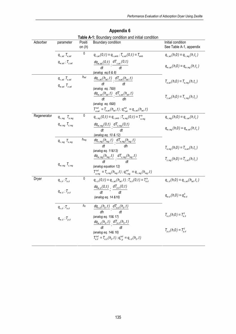
Performance Evaluation of Adsorption Dryer Using Zeolite
135
Appendix 6
Table A-1: Boundary condition and initial condition parameter Positi
on (h) Boundary condition Initial condition
See Table A-1, appendix Adsorber
ad,vq ad,aT
ad,wq ; ad,zT
0 amb,vad,v q)t,0(q = ; ambad,a T)t,0(T =
dt
)t,0(dq ad,w;
dt
)t,0(dTad,z
(analog eq.6 & 8)
ad,vq ad,aT
ad,wq ad,zT
had
dt
)t,h(dq adad,v;
dt
)t,h(dT adad,a
(analog eq. 7&9)
dt
)t,h(dq adad,w;
dh
)t,h(dT adad,z
(analog eq. 6&8)
)t,h(TT adad,aout
ad,a= ; )t,h(qq adad,v
out
ad,v=
)t,h(q)0,h(q creg,vad,v =
)t,h(q)0,h(q creg,wad,w =
)t,h(T)0,h(T creg,aad,a =
)t,h(T)0,h(T creg,zad,z =
reg,vq reg,aT
reg,wq reg,zT
0 amb,vreg,v q)t,0(q = ; in
reg,areg,a T)t,0(T =
dt
)t,0(dq reg,w;
dt
)t,0(dT reg,z
(analog eq. 10 & 12)
Regenerator
reg,vq reg,aT
reg,wq reg,zT
hreg
dt
)t,h(dq regreg,v;
dh
)t,h(dT regreg,a
(analog eq. 11&13)
dt
)t,h(dq regreg,w ;
dt
)t,h(dT regreg,z
(analog equation 12)
)t,h(TT regreg,aout
reg,a= ; )t,h(qq regreg,v
out
reg,v=
)t,h(q)0,h(q cad,vreg,v =
)t,h(q)0,h(q cad,wreg,w =
)t,h(T)0,h(T cad,areg,a =
)t,h(T)0,h(T cad,zreg,z =
d,vq ; d,aT
d,wq ; d,pT
0 )t,h(q)t,0(q adad,vd,v = ;in
d,ad,a T)t,0(T =
dt
)t,0(dq d,w ; dt
)t,0(dT d,p
(analog eq. 14 &16)
Dryer
d,vq ; d,aT
d,wq ; d,pT
hd
dh
)t,h(dq dd,v;
dt
)t,h(dT dd,a
(analog eq. 15& 17)
dt
)t,h(dq dd,w;
dt
)t,h(dT dd,p
(analog eq. 14& 16) )t,h(TT dd,a
outd,a = ; )t,h(qq dd,v
out
d,v=
)t,h(q)0,h(q cadad,vd,v =
0
d,wd,w q)0,h(q =
0
d,ad,a T)0,h(T =
0
d,pd,p T)0,h(T =

Chapter 6
136
Table A-2: Material properties and equipment data
Notation Parameter Value
colad ID;h Height and inside diameter of adsorber, m 0.24;0.15
pipeID inside diameter of pipe, m 0.05
ddd h;l;w Width, length and height of dryer, m 0.3;0.3;0.4
Weight of zeolite used (gram) 2500
p,paz,pa S;S Specific surface area of zeolite) and product (m2/g)[16] 20; 20
t Time, minute
pz ;εε Porosity of zeolite and product in bed 0.3;0.4
zρ Density of zeolite (kg/m3)[16] 736.5
pρ Density of product (kg/m3) 36
aρ Density of air (kg/m3) 1.08
zU ; pU Overall heat transfer coefficient of zeolite[17] ; product, kJ/m2min°C 0.116
∆Hads Latent heat of water adsorption (kJ/kg)[15] 4400
cpv Specific heat of vapor (kJ/kg oC) 1.93 cpa Specific heat of dry air (kJ/kg oC) 1 cpw Specific heat of water (kJ/kg oC) 4.2 cpp Specific heat of dry product (kJ/kg oC)[16] 0.920 ∆Hv Latent heat of water evaporation (kJ/kg) 2500
ad,airG Flow rate of air for adsorber or dryer, kg/h 1.70
reg,airG Flow rate of air for regenerator, kg/h 2.00
ambT Ambient temperature (measured), °C 17-20
RHamb Ambient relative humidity (measured), % 35
amb,vq Humidity of ambient air 0.0065-0.0090
reg,aT Temperature of inlet regenerator 110-130
in
d,aT Temperature of inlet dryer 50
Initial condition for shift 1 (first shift) )0,h(q ad,w Water in zeolite, kg water/kg dry zeolite 0.025
)0,h(T ad,z Temperature of zeolite, °C 40
)0,h(q ad,v Humidity of air, kg vapor/kg dry air 0.008
)0,h(T ad,a
Adsorber
Temperature of air, °C 40
)0,h(q ad,w Water in zeolite, kg water/kg dry zeolite 0.16
)0,h(T reg,z Temperature of zeolite, °C 80
)0,h(q reg,v Humidity of air, kg vapor/kg dry air 0.008
)0,h(T reg,a
Regenerator
Temperature of air, °C 120
)0,h(q d,w Water content in product, kg water/kg dry product 10
)0,h(T d,p Temperature of product, °C 18
)0,h(q d,v Humidity of air, kg vapor/kg dry air 0.001
)0,h(T d,a
Dryer
Temperature of air, °C 50

Chapter 7
Adsorption Drying with Zeolite:
Evaluation and Future Development

Chapter 7
138
1. Research achievements and evaluation
The drawback of low and medium temperature drying in processing food products and
other heat sensitive products is the high energy consumption. The energy efficiencies are in the
range of 25-60%, which means that to remove one kilogram of water from a product the energy
equivalent of 1.6-4.0 kg of steam is required. With the current drastic increasing prices for fossil
fuels, the operational costs for drying increase along a corresponding trend. Due to the world
wide increasing demand for energy it is expected that in the future the increase of operational
cost for drying process will continue.
This situation makes the development of efficient drying methods for high quality heat
sensitive products more and more important, and raises a challenge for research in drying
technology. However, during the last decades, innovation and research in drying technology
tended to reach a saturation level and a further significant reduction in energy consumption
seemed not feasible. Nevertheless, positive results were obtained in zeolite drying to improve
energy efficiency for low and medium temperature operations which are suitable for retaining high
quality of heat sensitive products. My research questions are:
1. How to use zeolite to enhance the energy efficiency of drying systems,
2. How to recover heat flows in dryer-adsorption-regeneration system,
3. What is the potential for a multistage zeolite drying system?
4. How to design the zeolite drying process operation with proper dimension of equipment
5. Can the zeolite drying system be validated?
6. How to use the obtained knowledge to design an energy effective dryer
The principle of this research is directed on the improvement of the driving force in the
dryer by reducing the humidity of air through an adsorption system using zeolite before entering
the dryer. In this way, at least two advantages can be obtained:
1. the air humidity of the drying air is made low (more than 99% can be removed) which
increases the capacity of air for taking up water from the product and speeds-up the drying,
2. the air temperature increases due to the adsorption heat released during vapor removal
which reduces the heat demand for drying.
These advantages result in an energy efficient drying system. However, after taking the required
energy for regeneration of the spent zeolite into account, the overall energy efficiency
improvement is still marginal. Moreover, zeolite regeneration requires high temperatures which
increase the costs for hot utility.
To enhance the overall energy efficiency, heat is recovered with a heat exchanger
network designed on the principles of pinch technology and which is integrated with the zeolite

Adsorption Dryer: Evaluation and Future Development
139
dryer for recovering heat in the hot exhaust air from the regenerator. The hot air is reused to heat
the air which is fed to the regenerator, and the remaining heat is used to heat the dehumidified air
for drying. This method reduces the total heat that has to be supplied by a hot utility unit and
increases the energy efficiency of the zeolite dryer system as well. The energy efficiency of a
single-stage zeolite dryer with 2-4 heat exchangers for heat recovery operating in the range of 60-
90°C is 70-75% which is 10-15% higher than that of a conventional dryer operating under
comparable conditions.
Multistage zeolite drying has potential for further improvement of the energy efficiency. In
such system product is dried in a number of succeeding stages. The product in the first stage is
dried with air dehumidified by zeolite. After passing an adsorber bed with zeolite, the exhaust air
from this stage is reused for product drying in a next stage. This concept is repeated several
times. The system can be operated as a co-current, counter-current or cross-current system. The
main benefit of the system is that the energy content of the exhaust air is reused several times.
Moreover, the released adsorption heat is utilized for drying in the succeeding stages. As a
consequence, product drying hardly requires heat supply. The required heat for the regeneration
of zeolite is kept low by pinch technology based heat recovery.
Multistage zeolite drying systems with 2,3 or 4 stages have been configured and
evaluated in combination with a heat exchanger network for heat recovery. Calculation results
obtained from a steady-state model based on overall mass and heat balances, showed that the
energy efficiency of a multistage system is significantly higher than that of conventional drying
systems and single-stage zeolite drying systems. The efficiency increases with the number of
stages, but a multistage system with 3 stages seems most effective. Above this number the
energy efficiency improvement is marginal and probably not sufficient to justify the increase of
system complexity. The counter-current dryer is most efficient and achieves an energy efficiency
of 88% for a 3-stage system. However, the heat recovery unit did not work effectively, since it
recovers only 16-20% of the total heat in the exhaust air.
To increase the effectiveness of the heat recovery the pressure of the hot exhaust air
from the regenerator is increased by using a compressor. As a result the temperature and dew
point of the air increase. Now, the system recovers more sensible heat and also latent heat from
vapor condensation. After taking into account the energy required for air compression, the
benefits were canceled. The other way is to use the compressed air to heat up other cold
streams. In this work air for an additional drying stage is heated. It brings the energy efficiency to
110-120% which implies that the energy consumption can be halved.
The focus in this work was on operational temperatures for drying in the range 60-90°C.
Besides this range the performance of the multistage zeolite dryer system was also evaluated for
operational dryer temperatures in the range 10-50°C. The dryer was compared with a
conventional drying system which uses dehumidified air obtained by condensation and in both
systems a heat recovery was applied. The energy efficiency of the multistage zeolite dryer
system is superior to the condensation system for ambient air temperatures in the range 10-25°C

Chapter 7
140
and relative humidity in the range 50-80%. Results showed that the energy efficiency of three-
stage zeolite dryer is 15-50% higher than that of a conventional condenser dryer.
To take the next step ahead towards the specification of the dryer characteristics and
dimensions and to integrate the drying and adsorption/desorption process, computational fluid
dynamic (CFD) calculations were performed for a combined adsorber-dryer-regenerator system.
The two-dimensional CFD model gives the temperature and water content distribution for all units
(dryer, adsorber and regenerator) and reveals characteristic phenomena relevant for finding
bottlenecks and to improve the design. The CFD calculations are powerful to estimate the
dimensions and type of equipment for industrial applications of multistage drying. The results
show that the technical realization and operation of a multistage dryer with a continuous moving
bed of zeolite (CMBZ-dryer) is feasible. Moreover, the energy efficiency obtained from the CFD
calculations is close to the results obtained from the steady-state model based on overall mass
and heat balances.
An experimental installation for a single-stage zeolite dryer has been set up to validate
the drying concept. The energy efficiency of the dryer was evaluated and compared to the energy
efficiency obtained from the models. By taking into account the heat recovery potential and heat
loss to the environment of the experimental installation, the experimental results are close to that
obtained with the steady-state model under comparable operational conditions.
It was found that the energy efficiency is most influenced by the ratio between the air flow
for drying and the air flow for regeneration of spent zeolite. Other important variables are ambient
temperature and the time during which the adsorber/regenerator units are used. Energy
efficiencies in the range 50-75% are obtained; the highest values are obtained for a ratio between
the air flow for drying and the air flow for regeneration of spent zeolite of 4:1.
Above, the work and achievements on 5 research questions have been discussed. An
essential aspect how to use the knowledge for the design of an effective dryer remains. A first,
step in that direction is discussed in the next section.
2. Outlook and perspective for realization
2.1. Adsorption dryer development
The results for the calculations for the drying concept using zeolite for air
dehumidification and the experimental results are impressive and match each other: it makes
further development of the zeolite dryer concept relevant. There are two possible directions for
development. The first is using the twin-columns with zeolite working in shift for air
dehumidification, the other one is a continuous system with a moving bed of zeolite. Figure 7.1
shows these concepts.
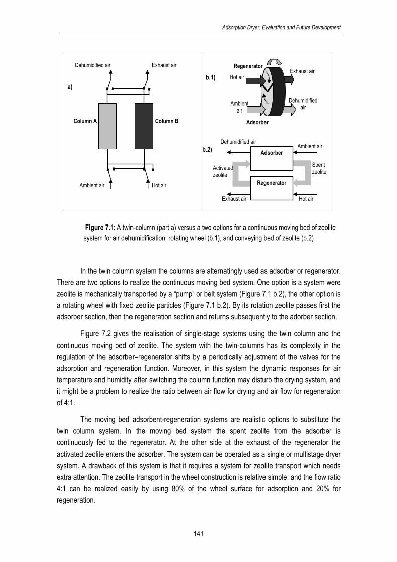
Adsorption Dryer: Evaluation and Future Development
141
Figure 7.1: A twin-column (part a) versus a two options for a continuous moving bed of zeolite
system for air dehumidification: rotating wheel (b.1), and conveying bed of zeolite (b.2)
In the twin column system the columns are alternatingly used as adsorber or regenerator.
There are two options to realize the continuous moving bed system. One option is a system were
zeolite is mechanically transported by a “pump” or belt system (Figure 7.1 b.2), the other option is
a rotating wheel with fixed zeolite particles (Figure 7.1 b.2). By its rotation zeolite passes first the
adsorber section, then the regeneration section and returns subsequently to the adorber section.
Figure 7.2 gives the realisation of single-stage systems using the twin column and the
continuous moving bed of zeolite. The system with the twin-columns has its complexity in the
regulation of the adsorber–regenerator shifts by a periodically adjustment of the valves for the
adsorption and regeneration function. Moreover, in this system the dynamic responses for air
temperature and humidity after switching the column function may disturb the drying system, and
it might be a problem to realize the ratio between air flow for drying and air flow for regeneration
of 4:1.
The moving bed adsorbent-regeneration systems are realistic options to substitute the
twin column system. In the moving bed system the spent zeolite from the adsorber is
continuously fed to the regenerator. At the other side at the exhaust of the regenerator the
activated zeolite enters the adsorber. The system can be operated as a single or multistage dryer
system. A drawback of this system is that it requires a system for zeolite transport which needs
extra attention. The zeolite transport in the wheel construction is relative simple, and the flow ratio
4:1 can be realized easily by using 80% of the wheel surface for adsorption and 20% for
regeneration.
b.1)
Ambient air Hot air
Dehumidified air Exhaust air
Column A Column B
a)
b.2)
Spent zeolite
Hot air
Activated zeolite
Dehumidified air
Exhaust air
Adsorber
Regenerator
Ambient air
Exhaust air
Dehumidified air
Ambientair
Hot air
Adsorber
Regenerator

Chapter 7
142
In both systems, the temperatures of the air flows are controlled by manipulating the heat
flow towards the heaters, and the flow of air is kept at set-point by air flow control. The moisture
content in product could be controlled by the temperature of air entering the dryer. However, in
practice, the moisture in product is often difficult to measure on-line. In that case either the
relative humidity or temperature of air exiting dryer is used to control the moisture in product.
These control loopsms are similar to standard controls applied in drying. Thus this system for
zeolite drying can be realized with current technology.
Figure 7.2:a. Single-stage zeolite dryer with fixed bed adsorber-regenerator working in shift; b. Single-stage zeolite dryer with moving bed adsorber-regenerator
Figure 7.3 presents a two-stage dryer systems with adsorber-regenerator working in shift
and a continuous moving bed of zeolite dryer. In both systems, the exhaust air from the dryer
passes the adsorber in stage 2, while the hot air exiting the first stage regenerator enters the
second stage regenerator. The extension to two stages improves the energy efficiency and can
be improved further by using 3 or 4 stages. The control loops are similar as for the single-stage
system and can be realized with common control systems.
b
Adsorber
Inlet product Outlet
product
Dehumidified Air
Heater
Heater Regenerator
Wet air
Ambient air
Ambient air
Heat Recovery
Exhaust air Dryer
TC
TC FC Outlet
product
Hot air
FC
TC
Belt moving bed
Exhaust air
Adsorber
Rotating Wheel
Dehumidified air
Regenerator
Ambient Air
Exhaust air Hot air
a
Column B
Inlet product
Outlet product Ambient
air
Dehumidified air
Hot air
Dryer
Heater Column A
Wet air
Ambient air
Exhaust air
Heat Recovery
Heater
TC
FC
FC TC
Exhaust air
TC

Adsorption Dryer: Evaluation and Future Development
143
Figure 7.3: a.Two-stage zeolite dryer with fixed bed adsorber-regenerator column working in shift; b.Two-
stage zeolite dryer with moving bed adsorber-regenerator
Wet air
a)
Stage 2
Column B
Ambient air
Dehumidified air
Hot air
Heater Column A
Ambient air
Exhaust air
Heat Recovery
FC TC
Inlet product
Outlet product
Wet air
product
Dryer Heater
TC
Column B
Hot air
Heater Column A
Air outlet regenerator 1
TC Heater
TC
Dryer
FC Stage 1
TC
Dehumidified air Exhaust
air
FC
Adsorber
Inlet product
Heater
Heater Regenerator
Wet air
Ambient air
Ambient air Heat
Recovery
Exhaust air
Dryer
Adsorber
product
Outlet product
Regenerator
Wet air
Dryer
Hot air
Stage 2
FC TC
TC
Heater
TC
TC
b)
Exhaust air Dehumidified
air
Dehumidified air
Heater
TC
Air outlet regenerator 1
Adsorber
Rotating Wheel
Dehumidified air
Regenerator
Ambient Air
Exhaust air Hot air
Belt moving bed
Belt moving bed
Stage 1

Chapter 7
144
3. Sensitivity analysis
Operational systems based on the twin-colums or continuous moving bed of zeolite may
differ in their performance under varying operational conditions. Therefore, both systems are
evaluated with respect to the energy efficiency for varying operational variables and process
constants. This evaluation is based on the following procedure:
1. Configuring a steady state model for the one and two stage systems for the twin-column
system and the continuous moving bed operation (see Figure 7.2 and 7.3).
2. Identifying the controllable and non-controllable inputs and the most important process
constants. The operational conditions and process constants from Chapter 6 are used.
3. Specifying the effect of the input variables and main process constant on the energy
efficiency for single stage and two stage operation by change of input -20% and +20% from
the defined operational conditions.
The results for the sensitivity analysis are given in Table 7.1. As concluded in previous
chapters, the energy efficiency for the two-stage system is better than that of the single-stage
system. Moreover, for the standard operational conditions the energy efficiencies for the twin-
column system and the system with continuous moving bed of zeolite are comparable. For the
same stage number, the trend for variations in the input variables and process constants on the
energy efficiency are identical. Hence, it can be concluded that there is no specific preference for
one of the systems.
From the sensitivity analysis the input variables that affect the energy efficiency are
identified. This result is useful to define a strategy to keep the process at the highest
performance. The effect of the process parameters is relevant for the construction of the
equipment. The results in Table 1 show that the ratio between air flow to the dryer and air flow to
the regenerator, and the flow of zeolite (for moving bed) are most important variables to control
the energy efficiency of the process. Increasing the air flow to the regenerator decreases energy
efficiency, while increasing the air flow for drying and the zeolite flow result in an improved energy
efficiency.
The ambient air temperature and product temperature as non-controllable variables affect
the performance significantly. Higher ambient and product temperatures reduce the total amount
of required energy for heating of air for drying and regeneration, and hence the energy efficiency
increases.
The drying rate constant is the process constant which affects the energy efficiency the
most. The result is according expectation as with a higher drying rate the dryer operates more
efficiently. It must be realized that in this work the dryer is used to evaporate free water at a
constant drying rate. The optimal conditions and equipment dimensions for drying products in the
falling rate drying period will be different.
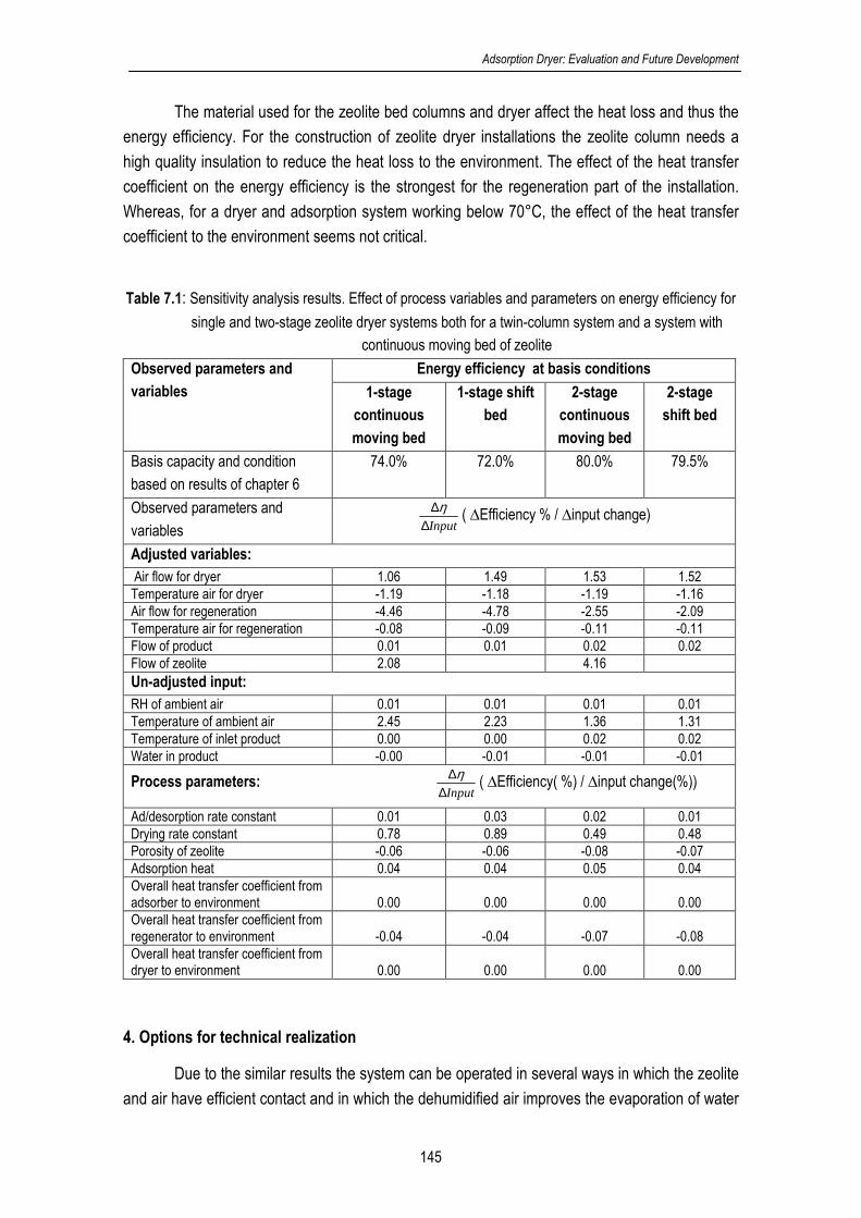
Adsorption Dryer: Evaluation and Future Development
145
The material used for the zeolite bed columns and dryer affect the heat loss and thus the
energy efficiency. For the construction of zeolite dryer installations the zeolite column needs a
high quality insulation to reduce the heat loss to the environment. The effect of the heat transfer
coefficient on the energy efficiency is the strongest for the regeneration part of the installation.
Whereas, for a dryer and adsorption system working below 70°C, the effect of the heat transfer
coefficient to the environment seems not critical.
Table 7.1: Sensitivity analysis results. Effect of process variables and parameters on energy efficiency for
single and two-stage zeolite dryer systems both for a twin-column system and a system with
continuous moving bed of zeolite Energy efficiency at basis conditions Observed parameters and
variables 1-stage
continuous
moving bed
1-stage shift
bed
2-stage
continuous
moving bed
2-stage
shift bed
Basis capacity and condition
based on results of chapter 6
74.0% 72.0% 80.0% 79.5%
Observed parameters and
variables Input∆∆η ( ∆Efficiency % / ∆input change)
Adjusted variables: Air flow for dryer 1.06 1.49 1.53 1.52 Temperature air for dryer -1.19 -1.18 -1.19 -1.16 Air flow for regeneration -4.46 -4.78 -2.55 -2.09 Temperature air for regeneration -0.08 -0.09 -0.11 -0.11 Flow of product 0.01 0.01 0.02 0.02 Flow of zeolite 2.08 4.16 Un-adjusted input: RH of ambient air 0.01 0.01 0.01 0.01 Temperature of ambient air 2.45 2.23 1.36 1.31 Temperature of inlet product 0.00 0.00 0.02 0.02 Water in product -0.00 -0.01 -0.01 -0.01
Process parameters: Input∆∆η ( ∆Efficiency( %) / ∆input change(%))
Ad/desorption rate constant 0.01 0.03 0.02 0.01 Drying rate constant 0.78 0.89 0.49 0.48 Porosity of zeolite -0.06 -0.06 -0.08 -0.07 Adsorption heat 0.04 0.04 0.05 0.04 Overall heat transfer coefficient from adsorber to environment 0.00 0.00 0.00 0.00 Overall heat transfer coefficient from regenerator to environment -0.04 -0.04 -0.07 -0.08 Overall heat transfer coefficient from dryer to environment 0.00 0.00 0.00 0.00
4. Options for technical realization
Due to the similar results the system can be operated in several ways in which the zeolite
and air have efficient contact and in which the dehumidified air improves the evaporation of water

Chapter 7
146
from the products. In the next sections some options for technical realization of multistage zeolite
dryer systems are discussed.
a. Continuous moving bed dryer designed in rotating zeolite jacket
The continuous moving bed zeolite can be combined with a rotating zeolite jacket
cylinder (see Figure 7.4). The zeolite jacket is divided in a section for adsorption and a section for
regeneration. These sections consist of several parts depending on the number of stages. Wet
product is fed to the dryer at desired flow, water content and temperature and is transported by
the conveyor belt through the dryer. After passing the adsorption section the heated dry air
contacts the product for drying. The product goes on to a next section which is separated from
the current section by a flexible baffle. The baffle makes that the saturated air is forced to the
following adsorption section to be dried and reused at the next step. By the rotation of the
cylindrical jacket, the zeolite is transported from the adsorption section to the regeneration section
and subsequently to the adsorption section again. The proposed system recovers energy in the
exhaust air from the dryer and regenerator.
Figure 7.4: Rotating zeolite jacket cylinder with belt dryer
b. Rotary wheel for multistage adsorber
In this system the adsorbent wheel is divided in a number of adsorption sections
(depending on the number of stages) and one section for regeneration (see Figure 7.5a). The
wheel rotates with a certain angular speed depending on the capacity of air flow. First, the
ambient air contacts the zeolite in section 1 of the wheel and passes then the first stage of dryer.
The wet air from the first drying stage is dehumidified in section 2 of the wheel and is
Product Inlet
Heater
Product Outlet
Regeneration section
Adsorption Section
Inlet Air
Inlet Air
Heat Recovery
Exhaust air

Adsorption Dryer: Evaluation and Future Development
147
subsequently used in the second stage of the dryer. This system is repeated. The zeolite comes
close to saturation in the last adsorption section of the wheel and then it will be regenerated in the
regeneration section by using hot air. The exhaust hot air from the regenerator can be recycled to
recover sensible heat.
Furthermore, for obtaining a higher efficiency it is an option to compress the exhaust air
from the regenerator (see Figure 7.5b). In this way, the exhaust air from the heat recovery unit
has a higher temperature and dew point as well as a higher total pressure. The exhaust air is
then contacted with air used as drying medium for an extra dryer in order to recover both sensible
and latent heat of vapour condensation. This combination makes the total heat recovery more
efficient.
Figure 7.5: Rotary wheel multistage adsorber in combination with compressor and extra dryer
(R=Regeneration; 1,2,3..adsorption zone)
c. Fluidized adsorber for the spray and fluidised bed dryer
The principle of this system is similar to the other multistage zeolite dryer systems. The
system consists of some adsorbers stages to dehumidify air. The zeolite particles are fluidized in
the adsorber. Part of the zeolite particles is withdrawn for regeneration. The activated zeolite is
returned to the adsorbers. The cyclones are used to separate air and particles. Of course, it is
also an option to apply the multistage rotary wheel system here. The wet product is dried in two
dryer stages; in this case a spray and fluidized bed dryer (see Figure 7.6). The spray dryer is
used to dry fresh wet product. Exiting spray dryer, the product passes a fluidized bed dryer to
finalize product drying.
1
2
3
R
Dryer 1 Dryer 3Dryer 2
Heat Recovery
Heater
Ambient Air
Ambient Air
Dry AirDry Air Dry Air
Wet Air Wet Air Wet Air
Hot Air
Exhaust Air
ProductIn Product
Out
1
2
3
R
Dryer 1 Dryer 3Dryer 2
Heat Recovery
Heater
Ambient Air
Ambient Air
Dry AirDry Air Dry Air
Wet Air Wet Air Wet Air
Hot Air
Exhaust Air
ProductIn Product
Out
Condenser
Extra Dryer
Ambient AirWarm air
50-70°Cwater
Wet Air
Compressor
1
2
3
R
Dryer 1 Dryer 3Dryer 2
Heat Recovery
Heater
Ambient Air
Ambient Air
Dry AirDry Air Dry Air
Wet Air Wet Air Wet Air
Hot Air
Exhaust Air
ProductIn Product
Out
1
2
3
R
1
2
3
R
Dryer 1 Dryer 3Dryer 2
Heat Recovery
Heater
Ambient Air
Ambient Air
Dry AirDry Air Dry Air
Wet Air Wet Air Wet Air
Hot Air
Exhaust Air
ProductIn Product
Out
1
2
3
R
Dryer 1 Dryer 3Dryer 2
Heat Recovery
Heater
Ambient Air
Ambient Air
Dry AirDry Air Dry Air
Wet Air Wet Air Wet Air
Hot Air
Exhaust Air
ProductIn Product
Out
Condenser
Extra Dryer
Ambient AirWarm air
50-70°Cwater
Wet Air
Compressor
1
2
3
R
1
2
3
R
Dryer 1 Dryer 3Dryer 2
Heat Recovery
Heater
Ambient Air
Ambient Air
Dry AirDry Air Dry Air
Wet Air Wet Air Wet Air
Hot Air
Exhaust Air
ProductIn Product
Out
Condenser
Extra Dryer
Ambient AirWarm air
50-70°Cwater
Wet Air
Compressor
a b
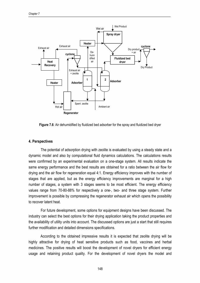
Chapter 7
148
Figure 7.6: Air dehumidified by fluidized bed adsorber for the spray and fluidized bed dryer
4. Perspectives
The potential of adsorption drying with zeolite is evaluated by using a steady state and a
dynamic model and also by computational fluid dynamics calculations. The calculations results
were confirmed by an experimental evaluation on a one-stage system. All results indicate the
same energy performance and the best results are obtained for a ratio between the air flow for
drying and the air flow for regeneration equal 4:1. Energy efficiency improves with the number of
stages that are applied, but as the energy efficiency improvements are marginal for a high
number of stages, a system with 3 stages seems to be most efficient. The energy efficiency
values range from 70-80-88% for respectively a one-, two- and three stage system. Further
improvement is possible by compressing the regenerator exhaust air which opens the possibility
to recover latent heat.
For future development, some options for equipment designs have been discussed. The
industry can select the best options for their drying application taking the product properties and
the availability of utility units into account. The discussed options are just a start that still requires
further modification and detailed dimensions specifications.
According to the obtained impressive results it is expected that zeolite drying will be
highly attractive for drying of heat sensitive products such as food, vaccines and herbal
medicines. The positive results will boost the development of novel dryers for efficient energy
usage and retaining product quality. For the development of novel dryers the model and
Heat Recovery
Heater
Heater
Exhaust air
Hot air
Exhaust air
Exhaust air + zeolite
Ambient air Spent zeolite
Dry product + air
Fluidized bed dryer
Spray dryer
Wet Product
Dry Product
cyclone
Wet air
Adsorber Adsorber
2 1
Regenerator
cyclone
De-humi dified air

Adsorption Dryer: Evaluation and Future Development
149
experimental set-up can be refined further. Furthermore, for the development of novel dryers the
sensitivity of the energy efficiency to changes in the operational conditions and product properties
will assist the search for an optimal design. In this work minimal attention has been paid to the
controllers to be applied, but it would be worthwhile to investigate the potential of advanced
control like optimal control, model predictive control and fuzzy control. A special challenge will be
the control for efficient start-up, and efficient switching between operational conditions.


151
Summary
Although drying takes a significant part of the total energy usage in industry, currently
available drying technology is often not efficient in terms of energy consumption. Generally, the
energy efficiency for drying processes ranges between 20-60% depending on the dryer type and
product to be dried. The high energy consumption and low energy efficiency have a high
environmental impact due to combustion of fossil fuel or wood used as energy source. Moreover,
the sources of fossil fuel are limited, the prices for energy increase and the world wide industrial
energy usage rises. In this context the development of efficient drying methods with low energy
consumption is an important issue for research in drying technology.
Adsorption drying with zeolite is considered as a potential technique to improve the
energy efficiency industrial drying. This approach is based on the dehumidification of the air for
drying through adsorption by zeolite. In such way, two main advantages are obtained: 1) the
driving force for drying is improved by the lower air humidity, 2) the release of adsorption heat
increases the temperature of the air for drying. These advantages result in a highly energy
efficient drying system, but after taking the heat for regeneration of spent zeolite into account, the
overall energy efficiency improvement is marginal.
The first challenge in this research was to realize an improvement of the energy
efficiency for the adsorption drying system with zeolite. To develop a solution, models based on
overall mass and heat balance for the dryer, adsorber and regenerator were used. The solution
for a better energy efficiency was found by combining the adsorption dryer with a heat recovery
system which recovers the energy in the hot off-gas of the regenerator. The energy efficiency for
a single stage zeolite dryer operating at 50-70°C with 2-4 heat exchangers for heat recovery is
10-18% higher than that of comparable conventional dryers.
Further improvement was realized by a multistage adsorption dryer system with zeolite.
In this system product is dried in a number of succeeding stages. After each stage the exhaust air
passes an adsorber where the air is dehumidified before feeding to the next drying stage. The
main benefit of the system is that the energy content of the exhaust air is reused several times.
Moreover, the released adsorption heat is utilized for the drying in the succeeding stages. The
regeneration process requires heat supply and is done for each adsorber or a combination of
adsorbers, but with pinch based heat recovery the energy input can be kept low.
Model calculations, using the same balances as in the previous step, were done for co-
current, counter-current and cross-current multistage systems. Results showed that the energy
efficiency increases with the number of stages and seems most effective for 2-3 stages. The
counter-current dryer is the most efficient and achieves an energy efficiency of 88% for a 3-stage
system. Compression of the exhaust air from the regenerator makes it possible to recover both
sensible and latent heat which can be used to heat ambient air for an extra dryer stage. After

152
taking into account the energy for compressing air, the energy efficiency achieves 110-120% that
implies that the energy usage is halved.
The performance of the multistage zeolite dryer system was also evaluated for lower
operational temperature in the range 10-50°C. The dryer was compared with a drying system
which uses condensation for air dehumidification and it was found that the energy efficiency of
the multistage zeolite dryer system is superior for ambient air temperatures in the range 10-25°C
and 50-80% relative humidity. Results showed that the energy efficiency of three stage zeolite
dryer is 15-50% higher than that of a conventional condensation dryer.
Till now overall mass and heat balances were used for the calculations and the
processes inside the dryer, adsorber and regenerator were ignored. Knowing what happens in
the system is essential for further specification and development of dryer, adsorber and
regenerator. For this purpose computational fluid dynamic (CFD) calculations were performed for
a combined adsorber-dryer-regenerator system. The calculations delivered information on the
internal temperature and water content distribution of all units and revealed characteristic
phenomena useful to find bottlenecks and to improve the system. The CFD calculations are also
powerful to estimate the dimensions and type of equipment for industrial applications of
multistage zeolite drying. The technical realization and operation of a multistage dryer with a
continuous moving bed of zeolite (CMBZ-dryer) is feasible. Moreover, the energy efficiency
obtained from the CFD calculations is comparable to the results obtained from the overall steady
state model.
The energy efficiency of a single-stage adsorption dryer using zeolite was experimentally
evaluated in a twin-column system working in shift. The columns containing zeolite are alternately
used for air dehumidification and for zeolite regeneration. The experimentally obtained energy
efficiency corresponded with the model results for the same operational conditions. To
extrapolate the experimental results to other operational conditions, a dynamic model for the twin
column system was fitted to the data. This model showed that the ratio between air flow for
drying and air flow for regeneration, and the ambient relative humidity and temperature affect the
energy efficiency the most. The results show that the energy efficiency of the system is around
75% if the ratio between air flow for drying and air flow for regeneration is 4:1.
Options to realize the zeolite dryer system are the twin-column, a continuous moving bed
of zeolite or rotating wheel. Systems characteristics are evaluated and compared in a sensitivity
analysis. Results showed that the systems have similar energy efficiency performance. Hence, it
can be noted that for industrial application, the continuous moving bed of zeolite or wheel system
to realize the dryer system.

153
Samenvatting
Hoewel drogen een belangrijk aandeel heeft in het industriële energieverbruik is de
huidige droogtechnologie vaak niet efficiënt in het energieverbruik. De energie efficiëntie varieert
tussen de toegepaste droogtechnieken en voor het te drogen product en ligt in het algemeen in
de range 20-60%. Het hoge energieverbruik en de lage efficiëntie hebben een grote impact op de
omgeving en het milieu door het gebruik van fossiele brandstoffen of hout voor verbranding. De
voorraden fossiele brandstoffen zijn beperkt, de energieprijzen stijgen snel en het wereldwijde
energiegebruik neemt steeds verder toe. Gezien deze ontwikkelingen is de ontwikkeling van
energie efficiënte drogers een belangrijk aandachtsveld voor onderzoek op het gebied van
droogtechnologie.
Adsorptiedrogen met zeolieten wordt als een kansrijke techniek gezien om de energie
efficiëntie bij industrieel drogen te verbeteren. Hierbij wordt gebruik gemaakt van drooglucht die
ontvochtigd wordt door de lucht door een zeolietbed te leiden. Op deze manier worden 2
belangrijke voordelen behaald: 1) de drijvende kracht voor drogen wordt verhoogd door de lagere
luchtvochtigheid, 2) de vrijgekomen adsorptiewarmte verwarmt de drooglucht. Deze twee effecten
zorgen voor een hoge energie efficiëntie, maar als de energie voor het regenereren van zeoliet in
beschouwing wordt genomen is de verbetering maar marginaal.
De eerste uitdaging voor dit onderzoek was dan ook het ontwikkelen van een aanpak om
adsorptiedrogen met zeoliet toch energie efficiënt te maken. Voor het ontwikkelen van
oplossingen zijn modellen voor de overall massa- en warmtebalansen voor alle units in een
adsorptiedroger (droger, adsorber, regenerator, etc.) opgesteld. De oplossing voor een betere
energie efficiëntie werd gevonden door het droogsysteem te combineren met een systeem voor
terugwinning van warmte uit de uitlaatlucht van de regenerator. De energie efficiëntie voor een
droger waarbij een inlaatluchttemperatuur in de range 50-70°C wordt toegepast, is bij het
toepassen van 2-4 warmtewisselaars 10-18% beter dan bij vergelijkbare traditionele drogers.
Een verdere verbetering is tot stand gebracht door het toepassen van een meer-traps
zeoliet droger. In dit systeem wordt product in verschillende stappen (trappen) gedroogd door
ontvochtigde lucht. De lucht die elke trap verlaat wordt elke keer opnieuw ontvochtigd met zeoliet,
voordat ze wordt gebruikt voor de volgende droogstap. Het belangrijkste voordeel is dat de
energie in de uitlaatlucht van elke stap niet verloren gaat, maar behouden blijft voor de volgende
droogstap. Verder draagt de vrijgekomen adsorptiewarmte elke keer bij aan het opwarmen van
de drooglucht. Het regenereren van verzadigd zeoliet voor alle adsorbers of combinatie van
adsorbers vraagt energie, maar door toepassing van op pinch technologie gebaseerde
warmteterugwinning kan de benodigde energie laag worden gehouden.
Modelberekeningen, die gebaseerd zijn op dezelfde balansen als eerder genoemd, zijn
uitgevoerd voor meestroom, tegenstroom en kruisstroom meer-traps systemen. De resultaten
laten zien dat de energie efficiëntie hoger wordt met het aantal trappen en lijkt het meest effectief
154
voor 2-3 trappen. Het tegenstroom systeem is het meest effectief en bereikt voor een 3-traps
systeem een energie efficiëntie van 88%. Comprimeren van de uitlaatlucht van de regenerator
maakt het mogelijk om naast de voelbare warmte ook de latente warmte terug te winnen
waarmee lucht voor een extra droogtrap kan worden verwarmd. Nadat het energieverbruik van de
compressor in rekening wordt gebracht wordt een energie efficiëntie van 110-120% bereikt. Dit
betekent dat het energieverbruik bij drogen gehalveerd kan worden.
Het meer-traps droogsysteem is ook geëvalueerd voor drogen met een luchttemperatuur
in de range 10-50°C en er is een vergelijking gemaakt met een traditionele droger waarbij de
lucht ontvochtigd wordt door condensatie. De resultaten voor de meer-traps droger zijn duidelijk
beter als de temperatuur van de aangezogen omgevingslucht in de range 10-25°C ligt en de
relatieve luchtvochtigheid van deze lucht tussen 50-80% is. Een 3-traps zeolietdroger heeft dan
een 15-50% betere energie efficiëntie.
Tot nu toe zijn overall massa- en warmtebalansen voor de berekeningen gebruikt en zijn
de processen binnen de droger, adsorber en regenerator buiten beschouwing gelaten. Kennis
wat er in het systeem gebeurd is essentieel voor verdere ontwikkeling van de apparatuur.
Computational fluid dynamics (CFD) berekeningen zijn uitgevoerd voor een gecombineerd
droger-adsorber-regenerator systeem. Deze berekeningen geven inzicht in de verdeling van
temperatuur en watergehalte in de apparatuur en zijn van belang om bottlenecks in het systeem
op te lossen. Verder kunnen ze gebruikt worden voor de dimensionering van meer-traps
installaties voor industrieel gebruik. De technische realisatie van continu getransporteerd zeoliet
bed (CMBZ-droger) blijkt op basis van de berekeningen haalbaar. Verder tonen de berekeningen
aan dat energie efficiëntie volgens deze gedetailleerde berekeningen overeen komen met
voorgaande berekeningen die gebaseerd zijn op de overall balansen.
De energie efficiëntie van een een-traps adsorber droger met zeoliet is experimenteel
vastgelegd in een twin-kolom systeem. De kolommen, die allebei een bed met zeoliet bevatten,
worden afwisselend gebruikt voor lucht ontvochtigen en zeoliet regeneratie. De experimenteel
bereikte energie efficiëntie komt overeen met de modelberekeningen onder vergelijkbare
condities. Om voorspellingen te doen voor andere operationele omstandigheden is een
dynamisch model van het twin-kolom systeem gefit met de verkregen data. Dit leverde het inzicht
dat de verhouding tussen de luchtstroom die via de adsorber naar de droger gaat en de
luchtstroom die gebruikt wordt voor regeneratie, de omgevingstemperatuur en relatieve
luchtvochtigheid het meeste effect hebben op de energie efficiëntie. Voor een verhouding tussen
de luchtstromen 4:1, wordt een energie efficiëntie van 75% bereikt.
Het twin-kolom systeem, het continu getransporteerd zeoliet bed en een roterend wiel
zijn mogelijkheden om de meer-traps zeoliet droogsysteem voor industriële toepassing te
realiseren. De systeemkarakteristieken blijken bij een gevoeligheidsanalyse vergelijkbaar en
daarom zijn het continu getransporteerd zeoliet bed en een roterend wiel goede opties om het
systeem voor industriële toepassing te realiseren.
155
Ringkasan
Pengeringan memerlukan energi yang besar dalam industri, namun teknologi
pengeringan yang ada belum cukup efisien. Umumnya efisiensi energi berkisar antara 20-60%
tergantung dari jenis pengering dan produk yang dikeringkan. Hal ini menyebabkan proses
menjadi boros energi dan meningkatkan emisi gas pencemaran hasil pembakaran bahan bakar
fosil. Terlebih lagi dengan terbatasnya sumber-sumber energi fosil, dan melambungnya harga
minyak mentah dunia, serta adanya industrailisasi, energi untuk proses pengeringan akan
semakin mahal. Dalam kontek ini maka pengembangan energi pengeringan yang efisien menjadi
hal yang sangat penting.
Proses pengeringan dengan cara adsorpsi air dari udara menggunakan zeolite
dipertimbangkan menjadi pilihan yang mampu mereduksi konsumsi energi dengan atau
meningkatkan efisiensi proses. Hal ini disebabkan oleh dua hal yaitu: 1). udara akan berkadar air
lebih rendah karena diserap zeolite sehingga menaikkan kapasitas udara untuk membawa uap
air dari bahan basah, 2). suhu udara selama proses penyerapan meningkat sehingga
mengurangi konsumsi energi dari unit pemanas. Bagaimanapun, setelah diperhitungkan dengan
panas untuk meregenerasi zeolite yang telah jenuh, peningkatan efisiensi ini sangat sedikit.
Selain itu, biaya proses menjadi makin tinggi karena proses regenerasi perlu suhu yang lebih
tinggi.
Tantangan pertama dalam riset ini adalah merealisasikan peningkatan efisiensi proses
pengeringan menggunakan zeolit. Yang pertama dilakukan yaitu perhitungan neraca masa dan
energi dari seluruh proses mulai dari adsorbsi, regenerasi, dan pengeringan. Dari neraca tersebut
dapat diidentifikasi aliran panas keluar yang dapat dimanfaatkan kembali. Pemanfaatan panas
terbuang ini dilakukan dalam rangkaian alat penukar panas dimana aliran udara panas yang
terbuang dari regenerator digunakan untuk memanasi udara luar yang digunakan untuk proses
regenerasi. Adanya unit ini maka kebutuhan panas untuk proses regenerasi menjadi lebih hemat.
Dengan menggunakan 2-4 alat penukar panas pada suhu pengeringan 50-70°C, efisiensi panas
dapat ditingkatkan 10-18% diatas efisiensi pengering konvensional.
Design lanjut telah dilakukan dengan merancang pengeringan multistage. Pada tahap ini,
air basah keluar dari unit pengering diproses ulang dalam unit adsorber untuk pengeringan tahap
berikutnya. Cara ini dilakukan berulang tergantung dari jumlah tahapan yang dirancang, sehingga
panas yang terbuang dari pengering sebelumnya dapat dimanfaatkan total untuk pengering
berikutnya. Selain itu panas yang dibebaskan juga semakin besar, dengan meningkatnya
kandungan air dalam umpan adsorber. Sementara itu proses regenerasi zeolite jenuh
memerlukan energi yang besar, namun dengan adanya unit untuk pemanfaatan panas kembali,
total panas yang diperlukan dapat diminimalkan.
Hasil perhitungan menunjukan bahwa efisiensi proses pengeringan menjadi 88% untuk 3
tahap dengan hanya memanfaatkan 16-20% energi terbuang. Untuk mendapatkan efisiensi yang

156
lebih tinggi, digunakan kompresor agar dapat memanfaatkan panas laten uap air di dalam udara
yang keluar regenerator. Namun setelah diperhitungkan dengan energi kompresor, peningkatan
efisiensi tidak diperoleh. Opsinya adalah menggunakan sisa panas hasil kompresi untuk
pemanasan pengering lainnya, sehingga diperoleh efisiensi keseluruhan sebesar 110-120% yang
menunjukkan energi tersebut adalah setengah dari yang digunakan pada pengering
konvensional.
Performansi pengeringan multi tahap juga telah diuji pada berbagai kondisi iklim dan
temperature operasi yang lebih rendah 10-50°C. Efisiensi energi yang dicapai juga dibandingkan
dengan pengering suhu rendah menggunakan condenser. Hasil menunjukkan bahwa efisiensi
energi sistim pengeringan menggunakan zeolite yang dioperasikan dengan umpan suhu luar 10-
25°C kelembaban relatif 50-80%, dapat lebih tinggi 15-50% daripada pengeringan bersuhu dingin
konvensional.
Pada tiga penelitian diatas, proses fenomena yang terjadi didalam pengering, adsorber
dan regenerator diabaikan dengan kata lain sistim perhitungan menggunakan model tunak serta
semua unit proses diasumsikan tercampur dengan sempurna. Desain lebih detil telah dilakukan
menggunakan model komputasional dinamika fluida dalam satu dan dua dimensi, untuk
mengetahui fenomena yang terjadi di dalam adsorpsi, regenerasi dan pengeringan yang akan
digunakan untuk menentukan dimensi alat proses. Perhitungan menunjukkan bahwa model dua
dimensi memberikan informasi profil suhu dan kandungan air selama proses, baik dalam fase
padat maupun gas,serta dimensi alat. Selain itu, desain alat sistim yang sederhana dapat
diketahui yaitu menggunakan zeolite yang bergerak secara kontinyu dengan efisiensi yang
sebanding dengan hasil perhitungan dalam kondisi tunak.
Pendekatan konsep diatas diuji menggunakan pengeringan zeolite dengan satu tahap.
Dalam pengambilan data menggunakan alat ini, efisiensi energi dihitung berdasarkan total bersih
energi yang diperlukan, serta energi yang digunakan pada unit pengering. Data-data ini juga
digunakan untuk memvalidasi model dinamika dari proses. Dengan perbandingan udara untuk
pengeringan dan udara untuk regenerasi zeolite 1:1, diperoleh efisiensi total 50-55%. Hasil yang
sama juga diperolah pada perhitungan menggunakan model tunak maupun dinamik. Dengan
ekstrapolasi kondisi menggunakan model dinamik, efisiensi sekitar 75% diperoleh pada
perbandingan udara untuk pengeringan dan udara untuk regenerasi 4:1, dimana hasil ini
bersesuaian dengan hipotesa awal perhitungan menggunakan sistim tunak.
Berdasarkan hasil-hasil diatas maka sistim pengeringan dirancang menggunakan zeolite
yang digerakan dengan belt atau roda berputar yang berisi dengan zeolite. Penggunaan ini
mampu mengurangi biaya konstruksi untuk operasi dan mengontrol proses. Untuk verifikasi,
sistim ini dibandingkan dengan sistim shif hasil eksperimen pada satu dan dua tahap proses
pengeringan berdasarkan karakter proses dan efisiensi energinya. Hasil menunjukkan bahaw
kedua sistim itu memiliki kesamaan untuk kedua hal diatas. Oleh karena itu disimpulkan bahwa
zeolit dalam belt atau roda berputar dapat digunakan untuk menggantikan model shif pada
pengembangan skala besar.
157
Acknowledgement
This thesis expresses my work for my doctoral research in Wageningen University. I
started by contacting my friend Hadiyanto for getting a possibility to enroll as PhD student in the
Systems and Control Group, Department Agrotechnology and Food Science, Wageningen
University. He introduced me to Dr.ir. A.J.B. van Boxtel. After intensive communicating, I got the
admission for my doctoral research.
At present, I have completed my thesis after doing a lot of effort, work and several
publications and spending much time. Here, I would like to express special gratitude to my wife
Okta Fitriana, and my children: Fathimah Az-Zahra, Musa Abdussalam, Syifa Salsabila Zein, and
Anisa Hanin Sajida who have sacrificed everything to support my study. I also apologize to them,
since my attention for them has been very-very minimal. I cannot describe with the words about
the greatness of their sacrificing. I express my appreciation also to my parents, Bapak Saeri
Cokrosuwignyo and Ibu Juhriyah, who gave motivation and prayed for my study. Especial for my
father Bapak Saeri Cokrosuwignyo, may God accept your kindness, forgive your sins, and place
you in the high level of Heaven.
I wish to gratefully thank Dr. ir. A.J.B. van Boxtel, Dr.ir. P.V. Bartels, Prof dr. J.P.M.
Sanders, and Prof dr.ir. G. van Straten for supervising, advising, and motivating me. Without
their guidance, it would be impossible for me to finish the doctoral study with published high
quality papers. I also appreciate to Rob Vos from Ebbens Engineering for the constructing of the
experimental equipment, Brentagg for zeolite supply and the Energy Research Program EOS of
the Dutch Ministry of Economics for their financial support conducted by SenterNovem.
I am grateful to my colleagues, especially Kees van Asselt, Johan Ploegaert and Bas
Speetjens for their assistance in using the sensors and to the development of labview programs,
Hadiyanto for nice discussion about research, Rachel who was always willing to give assistance
for Matlab and modeling, Wilko, Gerard and Karel for their nice courses, Marja and Gerda for
facilitating the administrative work, Dianika Lestari and Yessie Widya Sari for their assistance
during defense preparation, Jimy Perdana who was willing to assist for Adobe Photoshop and
cover design, Joni Adiansyah and Hasan Sawalha for their time as my paranymphs. I also
respect all other PhD students in Systems and Control group, and Valorization and Plant
Production Chains for the nice discussions. Last but not least, I thank to Hadiyanto, Adian, Adel,
and the big family of Indonesian Student Association who have done everything to encourage my
study in Wageningen.

158
159
Curriculum Vitae
Mohamad Djaeni was born in Kebumen, Indonesia, on February, 7th, 1971. He graduated
from Diponegoro University, Semarang Indonesia, in Bachelor Degree of Chemical Engineering
at 1995. After graduating, he worked as a lecturer in the Department of Chemical Engineering,
Faculty of Engineering, Diponegoro University. Two years later, he enrolled in the MSc program
at the University Technology Malaysia and obtained the degree Master of Engineering in for his
work in Chemical Process Control in 1999. The master research consists of the design of unit
operations using dynamic models, identifying process characteristics, selecting input-output
pairing for process control, and configuring a plant wide control system.
Since December 2004 he was admitted for the doctoral research work in the Systems
and Control Group, Department of Agrotechnology and Food Science, Wageningen University.
The topic of the research was the development of an efficient zeolite dryer for heat sensitive
products. This work is extensively decribed in this thesis.
Parallel with the doctoral research, he has joined several trainings, and assisted for the
course on Control Engineering and Process Control. Besides that he has been active member of
Indonesian Student Association (ISA) in the period 2005-2008, and was elected as vice president
of ISA for 2007/2008. Furthermore, he was co-chairman of the organizing committee for the
Indonesian Student Scientific Meeting 11 (ISSM11) held on May 13-15, 2008 at TU Delft
University under collaboration with ISA Wageningen, Delft, ISTECS chapter Europe, TU Delft
University, and Embassy or Republic Indonesia.
160
List of Publications
International Journal
1. Djaeni, M.; Bartels P.V.; Sanders J.P.M.; van Straten, G.; van Boxtel, A.J.B. Process
Integration for Food Drying with Air Dehumidified by Zeolite. Drying Technology 2007, 25 (1), 225-239
2. Djaeni, M.; Bartels P.V.; Sanders J.P.M.; van Straten, G.; van Boxtel, A.J.B. Multistage
Zeolite Drying to Enhance Energy Efficiency of Food Drying. Drying Technology 2007, 25
(6), 1053-1067
3. Djaeni, M.; Bartels P.V.; Sanders J.P.M.; van Straten, G.; van Boxtel, A.J.B. CFD for
Multistage Zeolite Dryer Design. Drying Technology 2008, 26 (4), 487-502
4. Djaeni, M.; Bartels P.V.; Sanders J.P.M.; van Straten, G.; van Boxtel, A.J.B. Energy
Efficiency of Low Temperature Multistage Adsorption Drying. Accepted for Drying Technology
(May, 2008)
Symposium
1. Van Boxtel, A.J.B.; Djaeni, M.; Bartels P.V.; Sanders, J.P.M.; Vos, R. System Integration for
Higher Energy Effciency in Adsorption Drying. NWGD Symposium, November 2006, Utrecht,
The Netherlands
2. Djaeni, M.; Bartels P.V.; Sanders J.P.M.; van Straten, G.; van Boxtel, AJB. Heat Efficiency of
Multistage Zeolite Systems for Low Temperature Drying. ADC 07, August 13-15, 2007,
Hongkong
3. Djaeni, M.; Bartels P.V.; Sanders J.P.M.; van Straten, G.; van Boxtel, A.J.B. Design of Multi
Tray Low Temperature Drier Using Air Dehumidified by Zeolite for Heat Sensitive Products.
NPS 7, October 29-30, 2007; Veldhoven, The Netherlands
4. Djaeni, M.; Bartels P.V.; Sanders J.P.M.; van Straten, G.; van Boxtel, A.J.B. Zeolite for
Efficient Drying. ISSM11, May 13-15, 2008; TU Delft, The Netherlands
Patent (published)
1. Van Boxtel, A.J.B., Bartels, P.V., Djaeni, M., Sanders, J.P.M., Van Straten, G. Assembly and
Method for Drying a Product. Submitted to Netherlands Patent No. P6012219NL
2. Van Boxtel, A.J.B., Bartels, P.V., Djaeni, M., Sanders, J.P.M., Van Straten, G. Assembly and
Method for Drying a Product. Internationale octrooiaanvraag PCT/NL2007/ 050578,
Internationaal number WO 2008/063059, 29 May 2008.

161
Overview of completed training activities
Name of the course
Graduate school/Institute Year
a. Discipline specific activities
Sustainable process design OSPT 2005
Advanced process integration & plant-wide control OSPT 2005
Physical modelling SENSE 2005
Particle based modelling OSPT 2006
Reaction kinetics in food products VLAG 2006
Systems and control theory SENSE 2006
Adsorptive processes OSPT 2007
NPT Congress Veldhoven OSPT 2007
ADC07 Hong Kong
HKUST 2007
b. General courses/activities
Time planning and project management PE & RC 2005
Intermediate tutored self study course English CENTA 2006
PhD presentation skills CENTA 2006
VLAG AIO week VLAG 2006
PhD Scientific writing CENTA 2007
Business competition WBS 2007
Indonesian Student Scientific Meeting, TU Delft
ISSM 2008
c. Optional
Writing research proposal 2005
Signal & systems modelling SCO/WU 2005
Renewable resources for the bulk-chemical industry VPP 2007

162